WPANEL - Windshield wiper Vetus - Free user manual and instructions
Find the device manual for free WPANEL Vetus in PDF.



User questions about WPANEL Vetus
0 question about this device. Answer the ones you know or ask your own.
Ask a new question about this device
Download the instructions for your Windshield wiper in PDF format for free! Find your manual WPANEL - Vetus and take your electronic device back in hand. On this page are published all the documents necessary for the use of your device. WPANEL by Vetus.
USER MANUAL WPANEL Vetus
Windscreen wiper controller
natural_image
Two electronic devices: a beige server unit and a black USB drive with six buttons (no visible text or symbols)WPANEL
Controlador de limpiaparabrisas
natural_image
Isometric technical drawing of a rectangular electronic component with internal slots and a black arrow indicating rotation (no text or symbols)Wissermotoren

natural_image
Technical illustration of a mechanical assembly with a screwdriver and directional arrows indicating motion (no text or symbols)Technische gegevens
Voedingsspanning
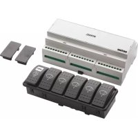
Using this windscreen wiper controller, a maximum of 5 wipers can be synchronised at low and high speed as well as in interval settings. The windshield wiper controller is also equipped with an automatic wipe/wash function. A maximum of 3 rain sensors can also be optionally connected.
The windshield wiper controller consists of a controller unit and a 6-switch panel to be built in. The controller unit is suitable for both 12 and 24 volts. Each output can have a maximum load of 120 W and is protected against overloading.
The windshield wiper motors to be used must have 1 or 2 wipe speeds and an automatic park setting.
WPANEL is delivered with:
1 x Controller unit
5 x Wiper switches
1 x Function switch
1 x Panel for 6 switches
2 x Blind panels
2 x Cable spade
1 x DIN Rail TS35
1 x Manual
Operation

Wiper switch
Each wiper (windshield wiper motor) has its own switch. The switch is used to turn the relevant wiper on or off. When a wiper is switched on, it follows the selected programme.
SPEED function switch

Whenever the SPEED switch
is pressed, the next wipe programme is selected.
The available programmes are:
1 interval 11 sec,
2 interval 9 sec,
3 interval 7 sec,
4 interval 5 sec,
5 interval 3 sec,
6 continuous low speed,
7 continuous high speed.
Once programme 7 is reached, pressing the switch selects programme 1 again. After a different programme is selected, the status lamp indicates the new setting by means of a series of flashes (1 to 7); this series is repeated once. See p. 23 'Using the SPEED button'.
On first use and each time after the current is switched off, the windshield wipers will wipe at low speed.
If the current has not been switched off, the wipers will wipe at the last interval setting or speed selected, unless the last setting was the highest speed.
The wiper motors can be operated automatically if rain sensors have been installed; consult the manual supplied with the rain sensors.
Windscreen spray switch

Pressing the 🎨 switch once will run the wipe/wash programme completely automatically:
- 3 seconds of spraying
- at least 3 wipes with simultaneousspray-ing,
- 3 final wipes.
Pressing the 🎨 switch and keeping it
pressed will maintain wiping with simultaneous spraying. All wipers will wipe, regardless of the position of the wiper switch.
Status light
The status light
of the function switch indicates the wiper controller status:
On: wiper controller is active,
Off: wiper controller is not active,
Fast flashing: current is too low or there is an internal fault,
Two series of flashes: selected programme indicated.
This is shown if a different programme is set and after the wiper controller is switched on.
Status LED
The status LED on the controller unit (between the + and - battery terminals) shows the status of the wiper controller:
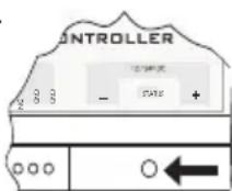
- Green: the wiper controller is active,
- Flashing green: the current is too low,
- Red: internal fault,
- Off: the wiper controller is not active.
Installation
Controller unit
Mount the controller unit as close as possible to the wiper motors. This means the wiring to the motors can be short. Mount the controller unit on a DIN rail TS35 (see p. 27)
Switches
Place the switches where they are easy for the user to operate. Install the function switch and one (1) on-off switch for each wiper motor. The switches are watertight and fitted with a gasket.
The switches can be built directly into an instrument panel, although the panel supplied can also be used. If not all switches are needed when the panel provided is used, the holes can be covered with the blind plates provided. The build-in panels do not have a gasket. Using the template provided, make a hole in the instrument panel.
Connections
See the connection diagram on p.24.
Current
The controller unit is suitable for both 12 and 24 volts DC.

The current for which the wiper motors are suitable must correspond to the onboard current (12 or 24 V).
The plus cable of the controller unit must include a main fuse and a switch.
Use a smaller fuse if applicable, appropriate for the total maximum current of the 5 wiper motors.
Use connecting wires with a sufficiently large diameter. See the connection diagram for the recommended minimum wire diameter. Connect the current to the cable spades provided ( 5 mm).
natural_image
Isometric technical drawing of a mechanical component with no visible text or symbols
Wiper motors Use only wiper motors of the same type; wiper motors must be equipped with an automatic park setting.
The wiper motors used must have 2 speeds to be able to use both low and high speeds. For example, Vetus type RWS and HDMC. Vetus type ORW is not suitable.
Connect the wiper motors to the controller unit as indicated in the diagram. Use connecting wires with a sufficiently large diameter. See the connection diagram on p.24 for the recommended wire diameter.
Switches
Connect the switches to the controller unit as indicated in the diagram. Use connecting wires with a diameter as indicated in the diagram.
Washer
A water pump or magnetic valve can be connected to the WASHER connection for a washer.

The current for which the water pump or magnetic valve are suitable must correspond to the onboard current (12 or 24 V).
Rain sensors
Consult the manual provided with the rain sensors to determine how to install them.
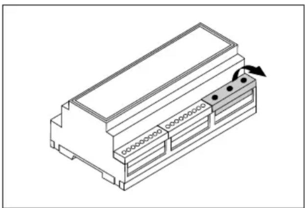
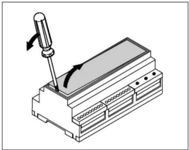
Safeguards
Each wiper motor is individually protected by a fuse. The washer pump is also protected by a fuse.
These fuses are under the lid of the controller unit (see diagram below on how to remove lid).
natural_image
Technical illustration of a mechanical assembly with a screwdriver and rotating component (no text or symbols)See 'Technical data' for fuse values.
Technical data
Current
12 or 24 V DC
Current received *): approx. 10 mA
Number of wipers: 5 max.
Maximum wiper motor output: 120 watts
Internal fuses
Wiper motors: 10 A (5 x)
Wiper pump or valve: 5 A (1 x)
Switches
Wiper switch:
Function: ON - OFF (1 x making contact)
Function switch:
Function: MOM - OFF - MOM
(2 x making contact, reverting to middle position) + lamp
*) Note: Controller unit only, not including current used by wiper motors.
Einleitung
natural_image
Isometric technical drawing of a mechanical housing or enclosure with internal components and a rotation arrow (no text or symbols)natural_image
Technical illustration of a mechanical assembly with a screwdriver and rotating component (no text or symbols)natural_image
Isometric technical drawing of a mechanical housing or enclosure with internal components and a directional arrow indicating rotation (no text or symbols present)
natural_image
Technical illustration of a mechanical assembly with a screwdriver and rotating component (no text or symbols)natural_image
Isometric technical drawing of a mechanical housing or enclosure with internal components and a directional arrow indicating rotation (no text or symbols present)
natural_image
Technical illustration of a mechanical assembly with a screwdriver and rotating component (no text or symbols)natural_image
Isometric technical drawing of a rectangular electronic component with internal slots and a directional arrow indicating movement (no text or symbols)natural_image
Technical illustration of a screwdriver operating on an electronic device with a slide (no text or symbols)13 Water pump or valve for washer
14 Connections for rain sensors (optional)