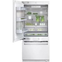
Vario RB 491 700 - Fridge GAGGENAU - Free user manual and instructions
Find the device manual for free Vario RB 491 700 GAGGENAU in PDF.


User questions about Vario RB 491 700 GAGGENAU
0 question about this device. Answer the ones you know or ask your own.
Ask a new question about this device
Download the instructions for your Fridge in PDF format for free! Find your manual Vario RB 491 700 - GAGGENAU and take your electronic device back in hand. On this page are published all the documents necessary for the use of your device. Vario RB 491 700 by GAGGENAU.
USER MANUAL Vario RB 491 700 GAGGENAU
Individual appliances with partition 7
At the end of the kitchen units 7
Installation 8
Installation room 8
Installation cavity 8
Furniture/fixtures 8
Base 8
Connecting the power 9
onnecting the water 9
Installation dimensions 10
Single installation 10
Side-by-Side installation 11
Water connection 12
Appliance dimensions 13
Required accessories and tools 14
Supplied accessories 14
Optional accessories 14
Other required accessories from specialist outlets .. 14
Tools 14
Other 14
Installation Instructions 15
-
Checking the installation cavity 15
-
Transport of the appliance 15
- Removing the packaging 16
4.Installation preparation 16 - Changing over the door hinges 17
6.Preparing the installation cavity 19 - Attaching an alternative anti-tip device 20
8.Preparing to connect the water 21 - Attaching the edge protection 21
- Side-by-Side installation 21
- Pushing the appliance into the installation cavity 22
12. Installing and aligning the appliance ... 23
- Attaching the appliance to the top of the cavity 24
- Attaching the individual appliance to the side of the cavity 25
- Checking that the finger guard moves easily 26
- Connecting the water to the appliance 26
17. Attaching the toe kick panel 27
- Commissioning the Appliance 28
19.Preparing the furniture doors 28 - Loading the appliance door 29
- Attaching the adjusting rail to the furniture door (refrigerator compartment) 29
- Attaching and aligning the furniture door (refrigerator compartment) 30
- Attaching the adjusting rail to the furniture door (freezer compartment) 31
- Attaching and aligning the furniture door (freezer compartment) 32
- Attaching the furniture door (refrigerator compartment) 33
- Attaching the furniture door (freezer compartment) 34
- Attaching the lower bracket 35

- Attaching the finger guard 36
- Attaching the covers 36
- Mounting of air separator 38
- Adjusting the door opening angle 38
- Changing the door spring 38
Read these instructions completely and carefully.
WARNING
These appliances are top-heavy and must be secured to prevent the possibility of tipping forward. Anti-tip protection is required.
Keep doors closed until the appliance is completely installed and secured per installation instructions.
Due to the weight and size of this appliance, and to reduce the risk of personal injury or damage to the product - TWO PEOPLE ARE REQUIRED FOR PROPER INSTALLATION.
This appliance must be properly grounded. See the section on "Connecting the power" on page 9.
Use this appliance only for its intended purpose.
Immediately repair or replace electric service cords that become frayed or damaged.
Unplug the appliance or switch off the fuse before cleaning or making repairs.
Repairs should be made by a qualified service technician.
CAUTION
Skill - Level - Installation of this appliance requires basic mechanical, carpentry and plumbing skills.
Proper installation is the responsibility of the installer. Product failure due to improper installation is not covered under the Appliance Warranty.
See the Owner's Manual for warranty information.
IMPORTANT
Save these instructions for local inspector's use. Observe all governing codes and ordinances.
Note to Installer - Be sure to leave these instructions with the Consumer.
Note to Consumer - Keep these instructions with your Owner's Manual for future reference.
General
These installation instructions are intended for use by qualified installers. All connections for water, electrical power and grounding must comply with local codes and ordinances and be made by licensed personnel when required. In the absence of a local code:
- In the U.S.A., in accordance with the National Electric Code, ANSI/NFPA70 - latest edition/State and Municipal codes and/or local codes.
- In Canada, in accordance with the Canadian Electric Code C22.1 - latest edition/Provincial and Municipal codes and/or local codes.

WARNING

WARNING - This indicates that death or serious injuries may occur as a result of not observing this warning.

CAUTION

CAUTION - This indicates that minor or moderate injuries or damage may occur as a result of not observing this warning.
NOTE
IMPORTANT NOTE / NOTE - This is used to draw the user's attention to something in particular.
Installation options
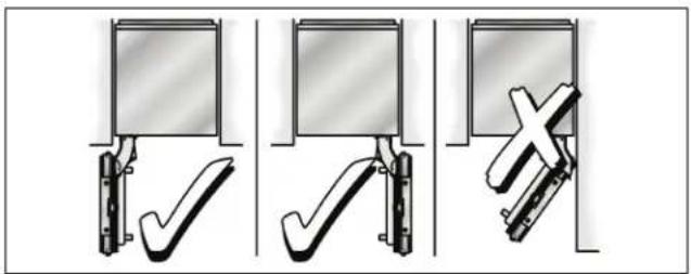
There are many different installation options.
These are limited only by the design of the kitchen and the function of the finger guard.
Individual unit
Side-by-Side
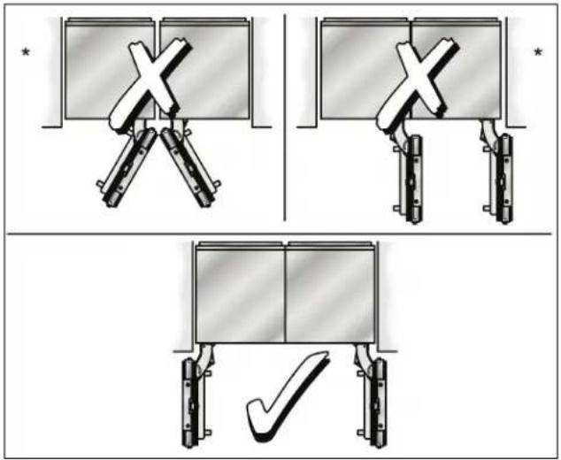
- Partition required!
When 2 appliances are installed Side-by-Side, the Basic Combination Side-by-Side Sealing kit must be used to ensure a stable connection.
See the section on "Optional accessories" on page 14.
Individual appliances with partition
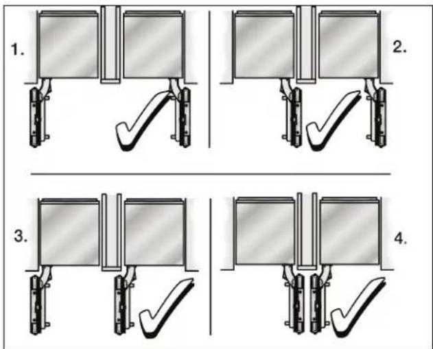
- When dimensioning the partition for model 4, note the thickness of the furniture fronts to prevent damage if the doors are opened at the same time.
- Use the Extreme Combination Side-by-Side Heating kit if the gap between the appliances is less than 6'' (160 mm).
See the section on "Optional accessories" on page 14.
- Minimum thickness of the partition ^5/_8^n (16 mm).
At the end of the kitchen units
If one side of the appliance is visible, a side panel must be used.
The side panel must be connected firmly to the wall, the floor and overhead furniture/fixtures before the appliance is placed in the cavity.
The dimensions of the side panel are taken from the opposite cavity wall. During installation ensure that the cavity is square and the exact size.
Installation
Installation room
The appliance should be installed in a dry, ventilated room.
The ambient temperature should not drop below 55^ (13^) or rise above 110^ (43^) , otherwise malfunctions may occur.
The installation location should not be exposed to direct sunlight and not placed near a heat source, such as an oven, radiator, etc. If installation next to a heat source is unavoidable, use a suitable insulating plate or observe the following minimum distances from the heat source:
1 1/4" (30 mm) from an electric cooker,
- 12" (300 mm) from an oil or solid-fuel cooker.
Installation cavity
It is important to observe the specified dimensions of the installation cavity for a trouble-free installation of the appliance and for the subsequent general view of the furniture front.
In particular ensure that the cavity is square.
Squareness can be checked by suitable means, e.g. spirit level, diagonal measurements, etc
The minimum thickness of side walls and the top wall must be 5 / 8 (16 mm).
The minimum thickness of toe kick panel must be 1 / 2 " (13 mm). A thickness of 3 / 4 " (19 mm) is recommended.
Furniture/fixtures
The new appliance is screwed securely to adjacent and overhead furniture/ fixtures.
For this reason it is essential that all attachable furniture/ fixtures are connected securely to the base or the wall by suitable means.
Base
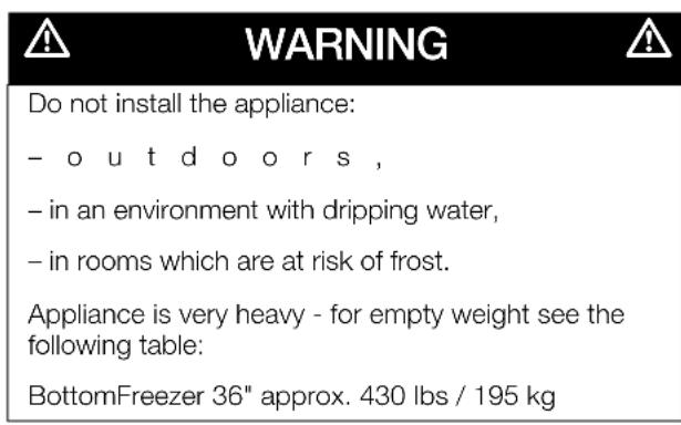
WARNING
A fully-load appliance is very heavy - for the load-bearing capacity at least see the following table: BottomFreezer 36" approx. 1200 lbs / 540 kg
To ensure that the appliance is installed securely and functions properly, the base must be flat and level.
The base must be made of a hard, rigid material.
The installation area must be the same height as the rest of the room.
On account of the heavy weight of a fully loaded appliance, a load-bearing base is required. If in doubt, contact an architect or a building expert.
Connecting the power
| WARNING |
| Electrical Shock Hazard |
| - Plug into a grounded 3 prong outlet. |
| - Do not remove ground prong. |
| - Do not use an adapter. |
| - Do not use an extension cord. |
| Failure to follow these instructions can result in death, fire, or electrical shock. |
The appliance comes with a 3-wire power supply cord, UL listed in the USA.
The appliance requires a 3-wire receptacle.
The receptacle must be installed by a licensed electrician only.
The socket must be fused with a 10 to 16 A fuse. Please observe in this coherence the following table:
| Appliance MAX load at one | time |
| BottomFreezer 36" 6.0 Ampere |
Orient ground prong to the bottom as shown in the pictures.
For the installation position of the receptacle see "Installation dimensions", page 10.
Additional grounding procedure
Some local regulations may require a seperate ground. In such cases, the required accessey ground wire, clamp and screw must be purchased seperately.
Never ground the appliance to plastic plumbing lines, gas lines or water pipes.
Grounding instruction
This appliance must be grounded. In the event of a malfunction or breakdown, grounding will reduce the risk of electric shock by providing a path of least resistance for the electric current
| WARNING |
| Improper connection of the equipment grounding conductor may result in electric shock. Have the appliance checked by a qualified electrician or service technician if you are in doubt as to whether the appliance has been properly grounded. |
Connecting the water
| CAUTION |
| Only connect the appliance to drinking water! |
A cold water connection is required for operation of the automatic ice maker. The water pressure must be between 25 and 120 p.s.i. (1.72-8.25 bar). The installation must comply with local plumbing regulations.
A separate shut-off valve must be installed for the appliance water connection.
The shut-off valve for the water connection must not be behind the appliance. It is recommended to place the shut-off valve directly next to the appliance (base unit) or in another easily accessible location.
When installing the water connection, observe the permitted installation areas for the pipe. For the permitted installation areas and dimensions see "Installation dimensions", page 10.
The supply pipe can be located at the side on the right (a), at the side on the left (b) or underneath (c).
Maximum outer diameter of the water pipe (without fittings): ^13 / _32 10 mm.
Attach a separate shut-off valve for the water connection in a suitable, easily accessible location. Do not use a self-piercing valve!
Single installation
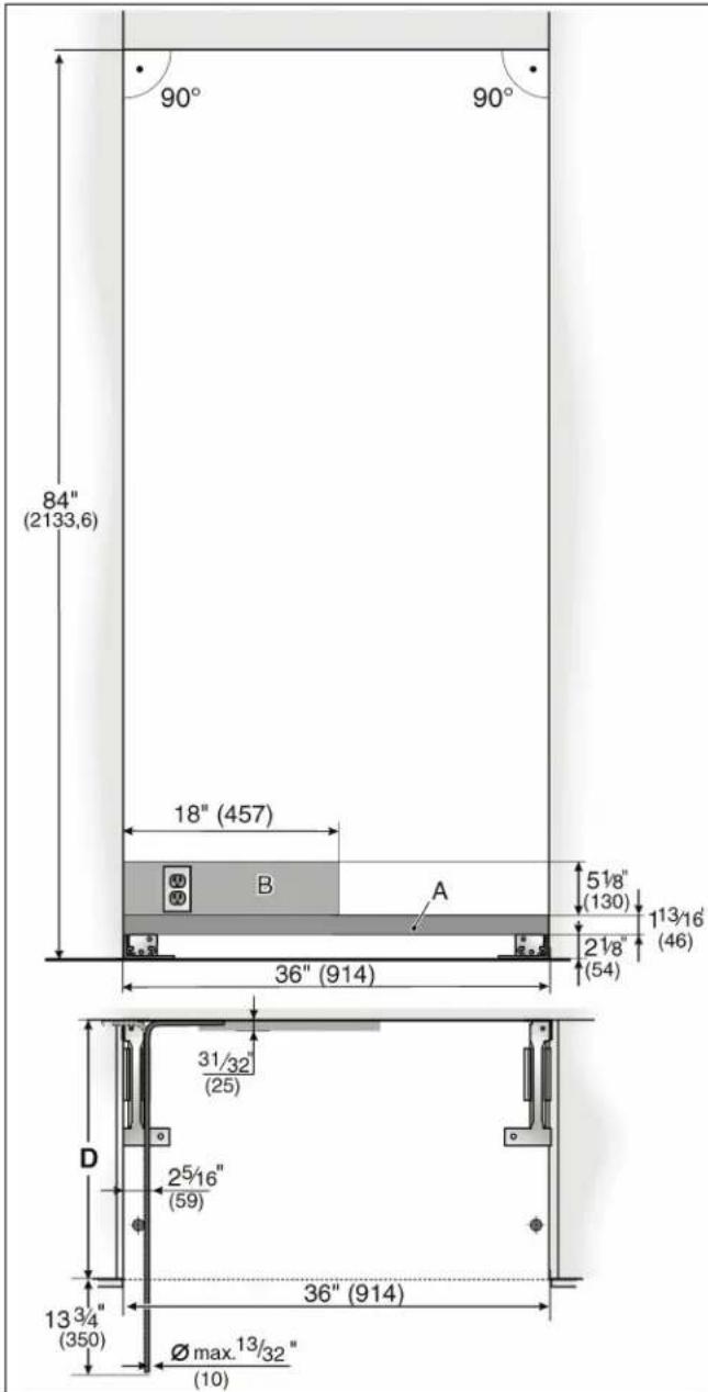
Legend:
A Area for installation of the water connection
It is recommended the water-box be placed adjacent to the installation cavity, so that it can be accessed for service without uninstalling the appliance. If this is not possible, place the recessed water box adjacent to the power supply socket elevated at the heights as referenced in areas A+B.
IMPORTANT!
It is strongly recommended the top panel boundary of the niche be of solid material ( /8 thickness).Make sure that the upper boundary is completely flush for a depth of at least 4^
IMPORTANT!
Make sure that the side walls of the niche are completely flush! If, for some reasons, a seperate niche cabinet is created, make sure that the furniture return area is at least 4" deep.
B Area for installation of the power connection
C Opening depth of niche, depending on kitchen design
$$ C = 2 4 ^ {\prime \prime} (6 1 0 m m) \text {m i n i m u m} $$
NOTE:
Cavity must be square. Side wall of the cavity must be flush.
Side-by-Side installation
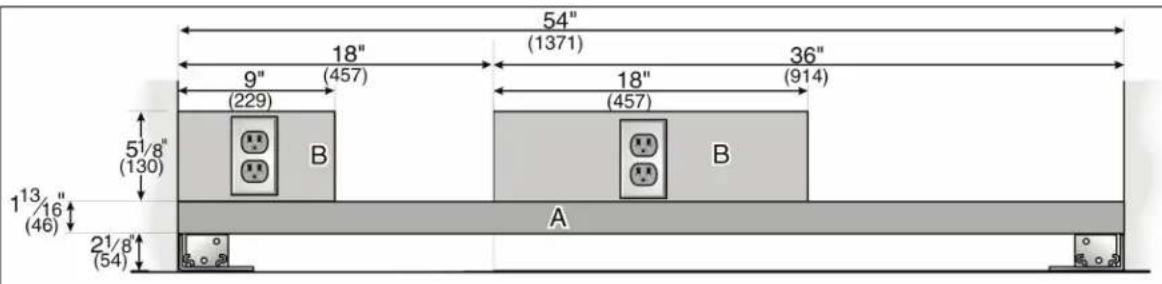
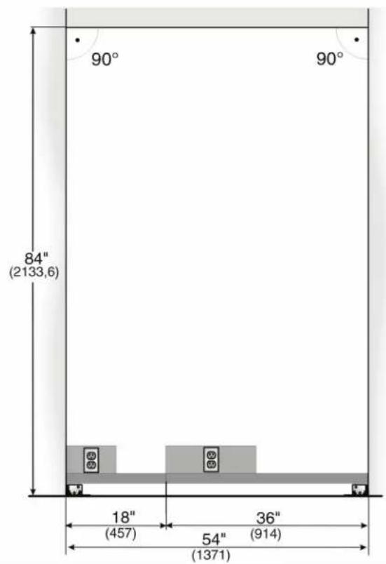
The cavity dimensions indicated above for the respective appliance apply to a Side-by-Side installation of two appliances.
The total width of the cavity results from the addition of the cavity widths indicated for the two appliances.
Example:
Freezer 18" / BottomFreezer 36"
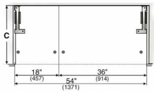
IMPORTANT!
It is strongly recommended the top panel boundary of the niche be of solid material (5/8 " thickness). Make sure that the upper boundary is completely flush for a depth of at least 4"
IMPORTANT!
Make sure that the side walls of the niche are completely flush! If, for some reasons, a separate niche cabinet is created, make sure that the furniture return area is at least 4" deep.
Legend:
A Area for installation of the water connection
It is recommended the water-box be placed adjacent to the installation cavity, so that it can be accessed for service without uninstalling the appliance. If this is not possible, place the recessed water box adjacent to the power supply socket elevated at the heights as referenced in areas A+B.
B Area for installation of the power connection
C Opening depth of niche, depending on kitchen design
C = 24" (610 mm) minimum
NOTE:
Cavity must be square. Side wall of the cavity must be flush.
Water connection
The supply pipe can be located
a) at the side on the right,
b) at the side on the left or
c) underneath.
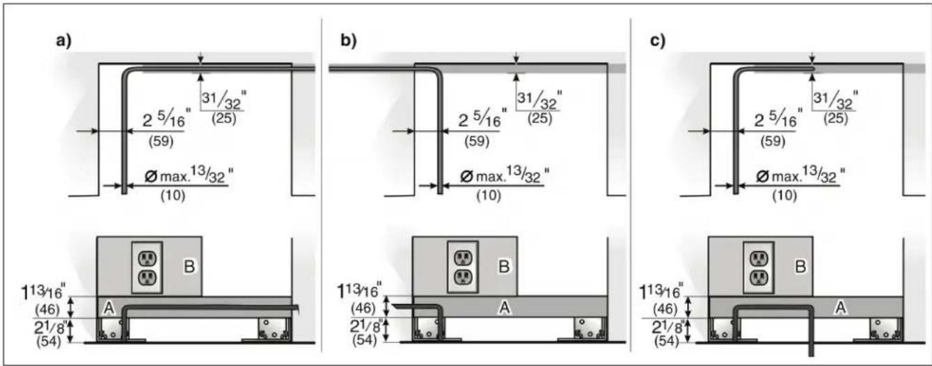
Legend:
A Area for installation of the water connection
B Area for installation of the power connection

Legend:
a) Adjustment in levelling legs +1 3/8 (35 mm) / -1/2 (13 mm).
b) Dimensions may vary.
c) Thickness of door panel may vary.
d) This dimension may vary depending on installation, panel thickness and kitchen hardware.
e) Unit dimensions
One design of the wooden panel displayed.
Required accessories and tools
Supplied accessories
- Installation instructions
- Operating instructions
- Installation kit
Optional accessories
Basic Combination Side-by-Side Sealing kit
For permanent connection of two individual appliances, e. g. Freezer next to Refrigerator.
Extreme Combination Side-by-Side Heating kit
If the gap between the appliances is less than 6^ (160 mm).
Panel unification part (Metal strip)
For connection of two furniture doors. Can be used for standard height furniture doors without further preliminary work.
Other required accessories from specialist outlets
Ice maker installation kit 1 / 4 " OD copper line
For connecting appliances which require water, e.g. for an ice maker.
Maximum outer diameter of the water pipe (without fittings): 13/32" (10 mm).
Tools
- Cordless screwdriver T20
-Torx screwdriver T20 - Torx bit T20 + magnetic holder
- ^5/16^ (8 mm) hex nut driver
Wood drills in different sizes -
Open end wrench 1 / 2 (SW 13 mm)
-
M u l t i g r i p p l i e r s
-
Adjustable wrench
- Cutter with adjustable blade
Metal tape measure
- S q u a r e
- Spirit level length 2^ (60 cm) and 4^ (1,2 m)
- Marking-out level, length at least 4^ (1.2m) for individual appliances or 7^ (2.0m) for Side-by-Side installation
Other
- Stepladder
Dolly, hand truck - Hammer drill for drilling holes in wall or floor
- Bits according suitable for material and in different sizes
- Wooden beam (cross section min. 3'' × 4'' ) as an alternative tilt protection, length according to the width of the installation cavity
- Wooden screws in different sizes
- Thin (max. 1 / 16 (1.5 mm), suitable material to protect the floor from damage (e.g. lino)
- Suitable material for covering and protecting furniture (e.g. protective sheets)
- Adhesive tape
NOTE
Before using, check whether the removed adhesive tape leaves adhesive residue on the work surfaces! Otherwise do not use on high-quality work surfaces.
Installation instructions
The following installation instructions describe the installation steps for various appliance types.
Therefore the diagrams may not be a true representation of your appliance.
Particular reference is made to special installation steps for individual appliance types.
1. Checking the installation cavity
| CAUTION |
| To ensure a safe, trouble-free installation and an optimum overall view of the subsequent furniture front, thoroughly check that the installation cavity complies with the installation requirements. |
Before starting the installation, check that the installation cavity complies with all requirements for a safe and trouble-free installation.
- Check the base.
Follow the instructions in the section on "Installation location" on page 7.
- Check the dimensions of the cavity.
- Check that the cavity is square.
- Check location of the socket.
Also follow the instructions in the section on "Connecting the power" on page 8 and in the section on "Installation dimensions" on page 9.
- Check location of the water connection (only for appliances with ice maker).
Also follow the instructions in the section on "Connecting the water" on page 8.
- Check attachment of the adjacent furniture/fixtures. All furniture parts in the vicinity of the appliance must be connected securely to the wall.
- Check that adjacent furniture/fixtures do not collide (door opening angle).
2. Transport of the appliance
| WARNING |
| The appliance is very heavy. Be careful, otherwise people who are helping may be injured or the appliance may be damaged. |
- Transport the appliance to a suitable installation location with suitable means of transportation (trolley, lifting truck or hand-driven truck).
- Secure the appliance during transportation to prevent it from overturning.
The appliance is 83^21 / 32 (2125 mm) tall. If the appliance cannot be transported in an upright position due to the structural conditions, the appliance can be transported horizontally.
| CAUTION |
| Do not erect the appliance via the side panels. Risk of damage to the appliance! |
When erecting the appliance, observe the required minimum height at the installation location according to the following table:
| Erection via appliance rear | Erection via appliance side panel |
| Minimum height 86" / 2185 mm | Do not erect the appliance via the side panels! |
| CAUTION |
| Always place the means of transport centrally on the rear side of the appliance. Never push it in from the front or from the side under the appliance. Risk of damage to the appliance! |


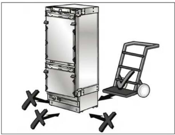
- Move the appliance with a hand truck securely.
3. Removing the packaging
| WARNING |
| - The appliance may tip over while it is being unpacked. |
| - The appliance is very heavy. |
| - When opening the appliance door, the appliance may tip forwards. |
| Be careful, otherwise people who are helping may be injured or the appliance may be damaged |
To protect the base from damage during installation:
- Attach a residual piece of carpet, lino, etc. to the floor with adhesive tape in front of the intended installation location.
- Remove transportation packaging:
Remove the cartoon. Use the cutter securely to protect the surface of appliance.
Remove packaging material.
Attach the power cord to the back of the appliance with a piece of adhesive tape.
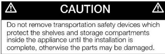
Remove transportation protection devices and lift appliance off the pallet - appliance is very heavy!
Remove accessories from the outside of the appliance.
Keep adhesive tape which was used to attach the supplied accessories to the appliance. It is used subsequently for attaching the edge protection to the cavity walls (see Section 9.).
Carefully open the appliance - risk of tipping over - and remove accessories and installation materials from inside the appliance. Close the door again.
- Check appliance for damage in transit.
Do not install the appliance if it is visibly damaged. If in doubt, contact your dealer.
4. Installation preparation
Unpack installation materials and accessories.
To improve allocation to the work steps, the packages are identified differently.
To do this, comply with the overview sheet attached to the appliance!
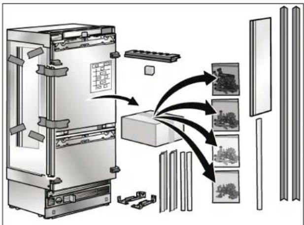
5. Changing over the door hinges
| WARNING |
| Before working on the hinge, release the spring. Risk of injury! |
| NOTE |
| -If it is not necessary to change over the door hinges, continue with the next installation step. |
| -The door hinges cannot be exchanged in the case of freezers with ice and water dispensers. |
Release the spring
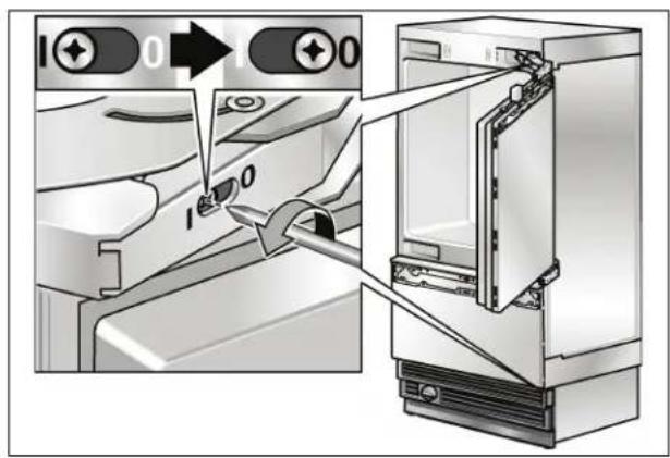
- Release the spring on the hinge. Loosen the screw from 1 to 0.
Exchanging the door hinges
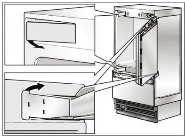
- Remove the hinge box covers.
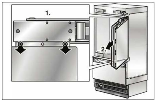
Unscrew the door.
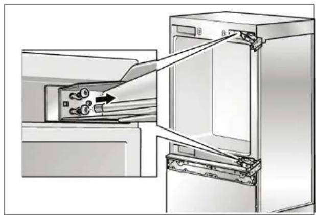
- Remove the hinges.
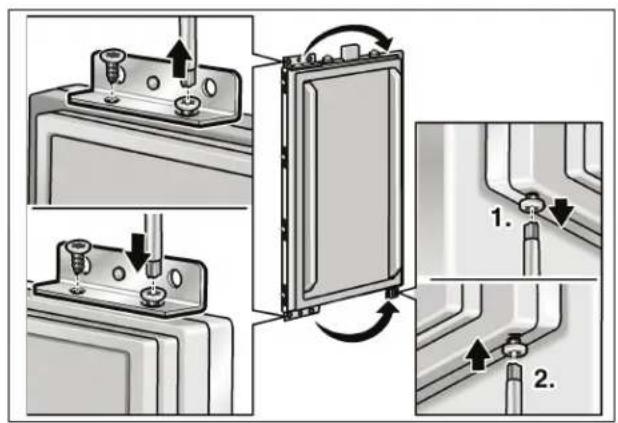
- Change over the fixation parts on the door.

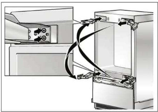
Fix the hinges on the appliance. Change the hinges crosswise!
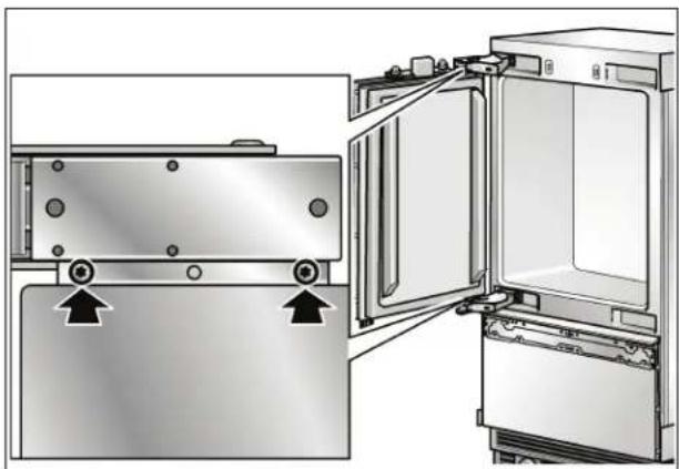
Fix the door.
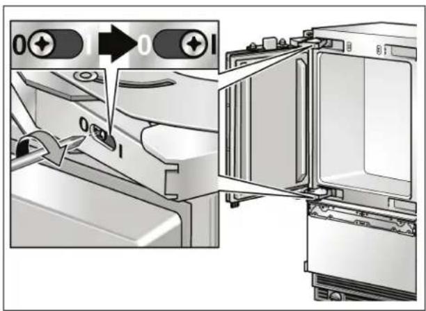
- Span the spring on the hinge. Tighten the screw from 0 to 1.
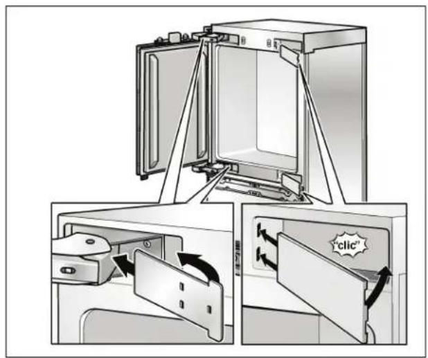
Fix the hinge box cover.
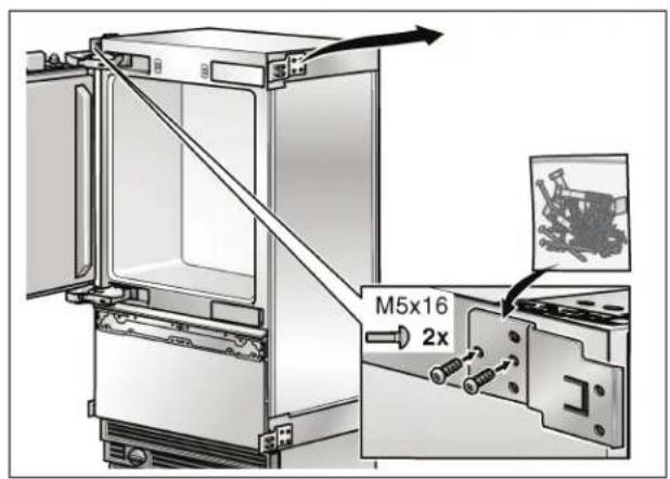
- Unscrew the fixing angle from the appliance.
From the set kit, fasten a new angle to the other side of the appliance.
6. Preparing the installation cavity
| WARNING |
| Assure that there are no electrical wires or plumbing in the area which the screws could penetrate. Risk of injury and damage! |
| NOTE |
| -2 anti-tip-brackets are required for each appliance or appliance combination (Side-by-Side). |
| -If possible, always screw the wooden beam to existing studs on the rear panel of the cavity. |
| -In some installations the sub-flooding or finished floor may necessitate angling the wood screws used to fasten the anti-tip-brackets to the back wall. |
| -The supplied set contains fastening screws for various applications. Select the fastening screws according to the local conditions. |
| -If the supplied fastening screws do not permit secure attachment of the anti-tip brackets and therefore the appliance, another method must be used to attach the anti-tip brackets securely. |
- Specify the attachment points of the anti-tip-brackets.
Specify the detailed dimensions according to the section on "Installation dimensions" starting on page 9.
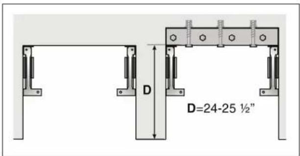
- If the installation cavity is deeper than the appliance, place a solid wooden beam behind the anti-tip-brackets and attach securely to the base or the wall.
The length of the wooden beam is equal to the width of the installation cavity!
Wood floor application
Use the wooden screws provided, see overview diagram "Use the screws in the screws set".
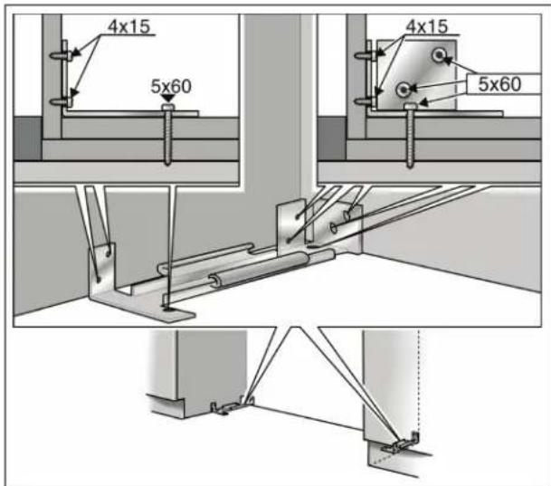
Drill pilot holes:
1/8" (3 mm) for the (5× 60mm) wooden screws
5/64" (2 mm) for the (4 × 15 ~mm) wooden screws
Being certain the screws penetrate through the flooring and into the wall plate a minimum of 34 (19 mm).
- Attach the anti-tip-bracket completely. Be sure screws hold tight.
Concrete floor applications
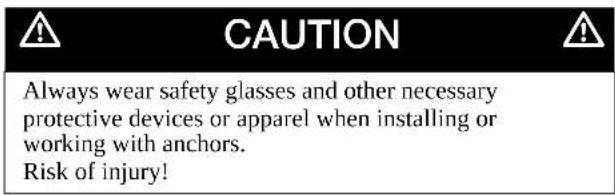
Not recommended for use in light-weight masonry material such as block or brick.
Not recommended for use in new concrete which has not had time to cure.
Do not use core drills to drill holes for this anchor.
Use concrete anchor M8 and M8 srew. Additional use the wooden screws provided, see overview diagram "Use the screws in the screws set".


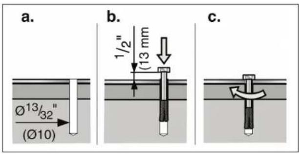
- Drill a ^13 / _32 (10 mm) diameter hole any depth exceeding the minimum embedment. Use the provided drill.
Clean hole or continue drilling additional depth. - Manually insert the screw into the wall plug until the screw begins to resist.
- Knock the wall plug and screw into the hole until the screw head is approx. 12 (13 mm) from the anti-tip bracket.
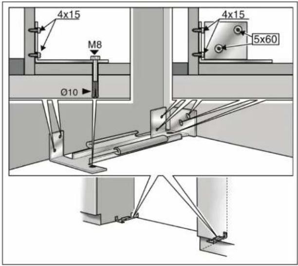
- Tighten the screw.
- Additionally use the supplied wood screws (if the subsurface allows).
7. Attaching an alternative anti-tip device
IMPORTANT NOTE
If the anti-tip brackets cannot be attached securely, an alternative anti-tip device can be attached. However, ensure that there is no play between the appliance and the anti-tip device.
If possible, always screw the wooden beam to existing studs on the rear panel of the cavity.
- Saw the wooden beam (cross section min. 3'' × 4'' ) to the required length.
Length is equal to the width of the installation cavity!
NOTE
- If the installation cavity is deeper than the appliance, select a beam which has a larger cross section or attach 2 beams.
- The beam must cover the appliance by at least 2^ (50.8 mm).
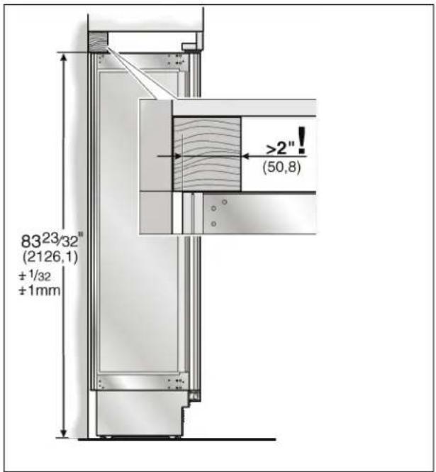
Mark the installation height (lower edge of the beam) on the rear panel of the cavity.
- Select screws according to the thickness of the wooden beam: length = min. 2.5 x beam thickness, diameter #12 or #14.
NOTE
Specify the number of screws according to the cavity width, thereby ensuring that the beam can be attached securely.
According to the subsurface:
- Locate wall studs near the rear panel of the cavity and mark drill holes in the beam
or
- Fasten suitable dowel into the rear wall.
- Predrill the wooden beam.
- Attach the wooden beam to the rear panel of the cavity.
8. Preparing to connect the water
(only for appliances which require a water connection)

CAUTION

Turn off the main water tap to prevent damage caused by leaking water.
- Attach the connecting pipe to the shut-off valve according to the instructions supplied by the manufacturer of the ice maker installation kit.
Install the connecting pipe.
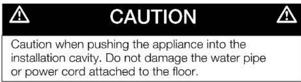
Always observe the indicated gap dimensions to prevent damage to the connecting pipe when pushing in the appliance.
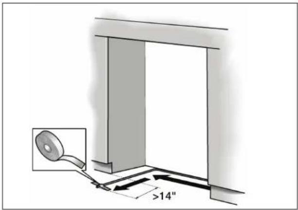
- Attach the connecting pipe to the floor with adhesive tape.
9. Attaching the edge protection

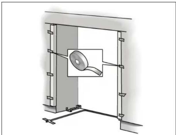
To protect the corners of the installation cavity, attach the supplied protective brackets with adhesive tape.
10. Side-by-Side installation
If a side-by-side installation is intended, now connect the two appliances together.
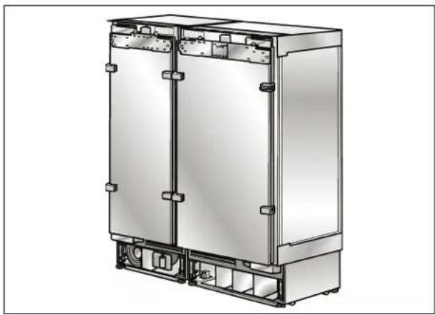
Detailed information on installation can be found in the separate installation instructions for the sealing kit for side-by-side installation.
The following work steps must be performed on two interconnected appliances.

11. Pushing the appliance into the installation cavity
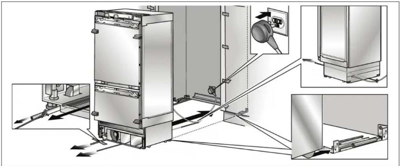
Put the mains plug into the socket.
Prevent the power cord from becoming caught.
Tie a piece of string to the middle of the power cord and feed forwards under the appliance. When pushing in the appliance, pull the cable forwards.
or
Using adhesive tape, stick the power cord to the floor centrally behind the appliance approx. 15^ (380 mm) away from the rear panel of the cavity.
- Carefully push the appliance into the cavity until the height-adjustable wheel interlock with the anti-tip brackets.
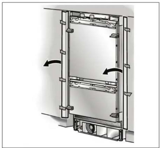
- Remove edge protection.
12. Installing and aligning the appliance
| CAUTION |
| Never use a cordless screwdriver! |
| Risk of damage to the appliance. |
| NOTE |
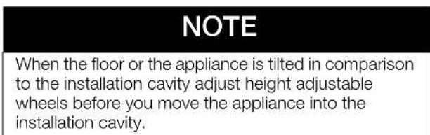
| - Do not twist or jam the appliance inside the cavity! When unscrewing the height-adjustable feet, proceed gradually: Always alternate between left and right, left and right, etc.. |
| - The adjustment of the rear feet is facilitated if the appliance is unloaded at the rear. |
| - If using a wooden beam as an alternative anti-tip device according to point 6 of this installation manual, rotate the appliance all the way towards the wooden beam. |
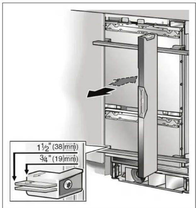
- Align the appliance with the furniture fronts.
Place marking-out level over the installation aid parts on the door.
The installation aid parts on the door have been designed for the following total thickness of furniture doors:
$$ \begin{array}{l} - \quad 3 / _ {4} ^ {\prime \prime} (1 9 m m) \ - \quad 1 ^ {1} / _ {2} " (3 8 m m) \ \end{array} $$
Always take account of the possible differing thickness of the furniture fronts which are to be fitted subsequently.
The height-adjustable feet at the front and rear can all be adjusted from the front.
Front: with open-ended wrench 1 / 2 (SW13)
Rear: with 5 / 16 (8 mm) hex nut driver via flexible shaft.
A mark is attached to the appliance base and is used as a standard gage for height adjustment. When adjusting the height, align this mark at a height of 1^1 / 2 (32 mm) above the floor.
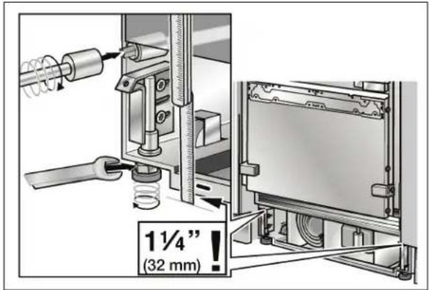
- Unscrew the height-adjustable feet until the mark on the base has reached the indicated guide dimension (1^1 / 4^n / 32mm)
NOTE
It is very important to comply with this dimension for the subsequent alignment of the furniture fronts.
Align the furniture fronts with the spirit level.
13. Attaching the appliance to the top of the cavity

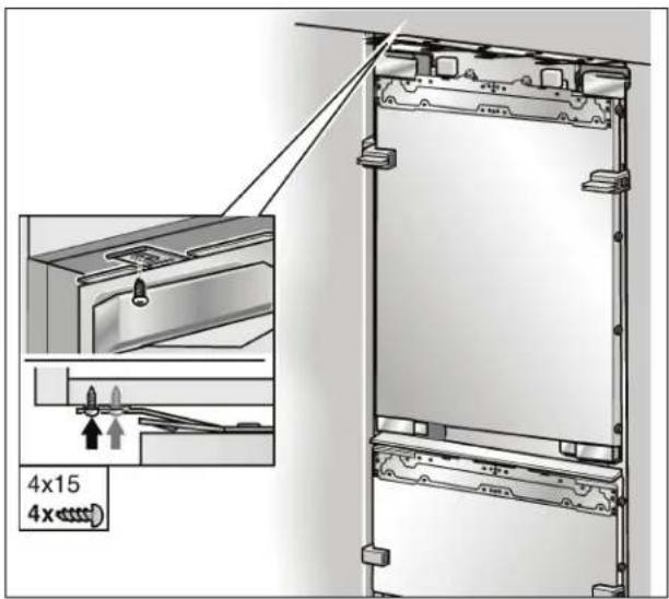
- Screw the attachment plate lugs (top) to the overhead furniture/fixtures.
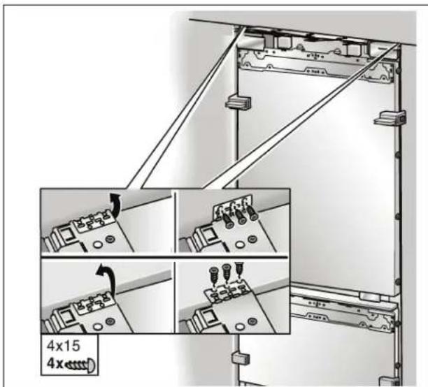
Fix the attachment plate side lugs (top) depending on the installation situation.
NOTE
If there is no gap or only a slight gap, it is not necessary to fix the side lugs.
If there is a fairly large gap above the appliance, fit a wooden beam above the appliance, ensuring that the wooden beam fits the gap exactly.
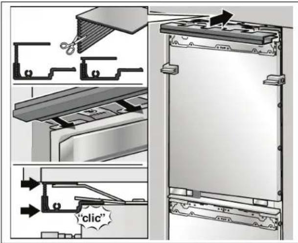
- Attach the cover strip to the attachment plate (top). Shorten the fitting strip to the required height!
NOTE
In the case of a side-by-side installation connect both cover rails to the bolt included in the installation accessories for side-by-side installation
14. Attaching the individual appliance to the side of the cavity
To attach the appliance at the side, first take the drawers out of the freezer compartment.
The upper drawer must first be removed before the door drawer can be taken out.
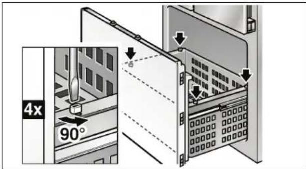
- Screw the closures by 90^ on the pullout using a screwdriver.
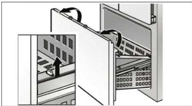
To take out, lift the drawers slightly and take out.
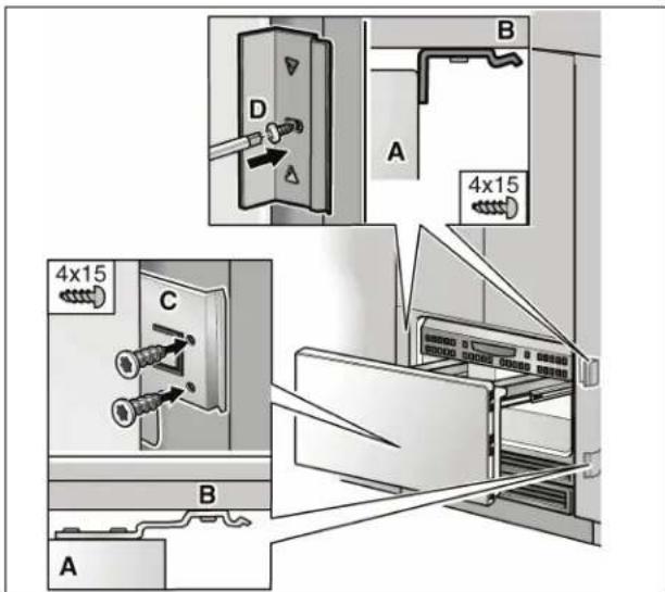
A
Appliance
B Cabinet part
- Screw on the bars of the fastening sheets (C) with the cabinet parts located next to them.
- Screw on the angle (D) for fastening the cover ribs.

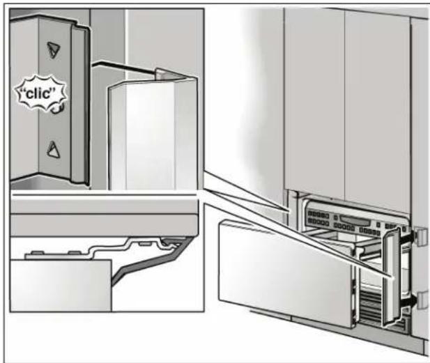
- Attach the cover ribs to the fastening plates and the angles.
Re-insert drawers:
- To place in, lift the front of the drawers slightly and place into the chest of drawers. Lower the drawer and slide it backwards.
- Screw the closures by 90^ on the pullout using a screwdriver.
15. Checking that the finger guard moves easily

It is now essential to check that the finger guard moves easily. At a later time any required corrections will be more difficult.
Note:
The supplied finger guard can be used for both sides of the door hinges.
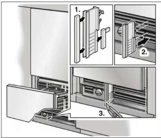
The finger guard must be shortened to the required length on account of the different installation positions.
- Shorten finger guard on the upper side 55mm above the cover strip (1.).
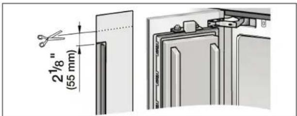
- Push the cut remnant on the hinge side into the gap between the appliance and cavity wall.
It must be possible to push in and pull out the part easily (2).!
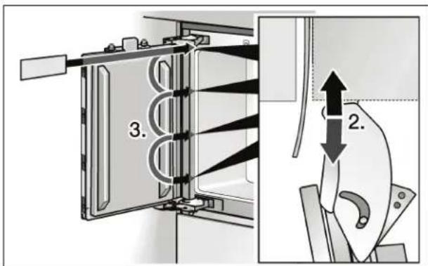
Check ease of movement over the entire height of the door (3.).
16. Connecting the water to the appliance

CAUTION

When bending the water pipe, do not kink it, otherwise there is a risk of leaks and water damage.
NOTE
When connecting the water pipe to the solenoid valve of the appliance, follow the instructions supplied by the manufacturer of the ice maker installation kit enclosed with the installation manual.

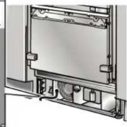
- Remove the cap from the appliance connection (1.).
- Bend the water pipe according to the location of the connection on the appliance (2.).
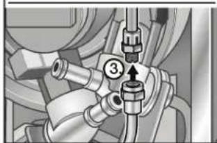
- Push the union nut and seal onto the water pipe.
- Push the end of the water pipe into the appliance connection and screw on the union nut (3.). Tighten hand-tight.
Using the open-ended wrench, tighten the union nut. Do not overturn! - Open the shut-off valve and main water tap.
- Check the connection on the shut-off valve and on the appliance for leaks.
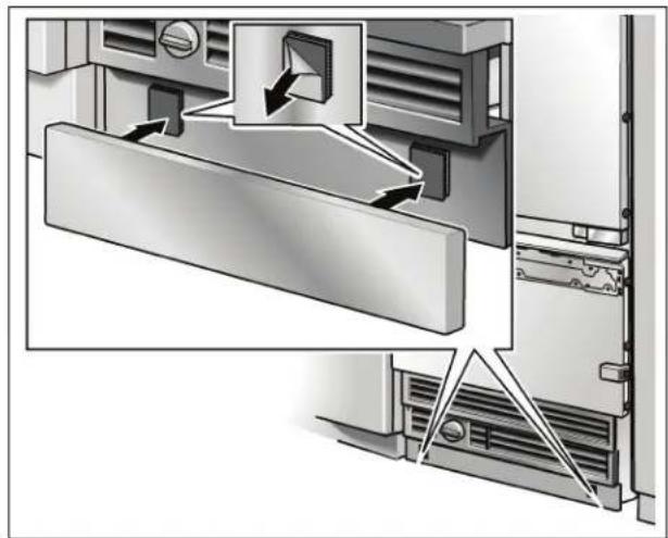
17. Attaching the toe kick panel
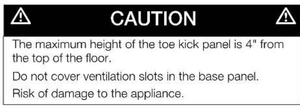
If required, cut the toe kick panel to the required length.
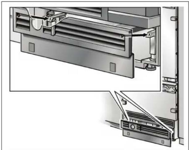
- Attach the base panel to the appliance.
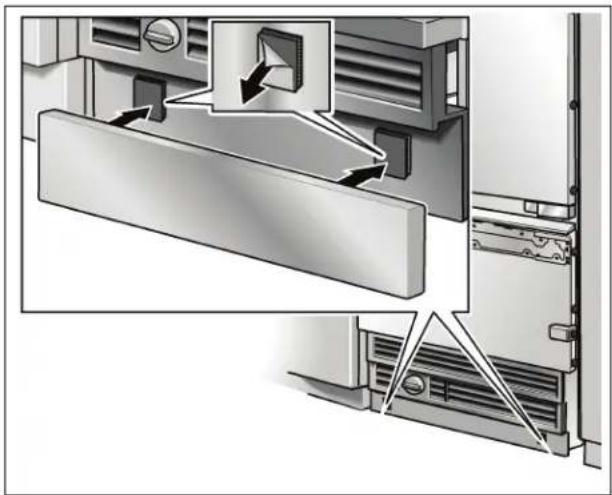
- Remove the protective film from the adhesive pads on the Velcro.
- Fit the toe kick panel to the base panel and press firmly into place.
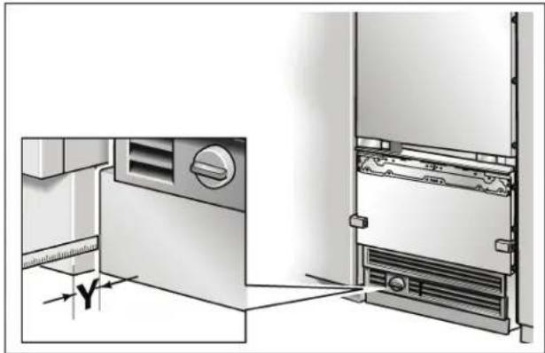
- Put on the base panel (do not screw on) and measure the difference in depth Y between the base panel and toe kick panel of the adjacent furniture.
- Remove the base panel.
- Loosen the brackets for attaching the base panel and push in all the way.
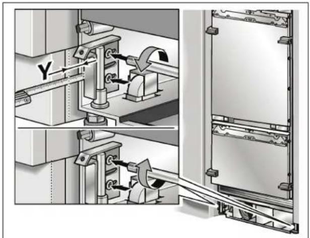
Pull out the brackets by the measured amount Y.
Screw the brackets tightly


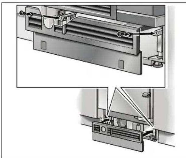
- Attach the base panel.
NOTE
If required, the toe kick panel can be screwed to the base panel. There are screw holes in the base panel near the Velcro.
18. Commissioning the Appliance
To guarantee the accuracy of the following working steps and thus the appearance of the overall kitchen front later on, the appliance should now be operated.
- Open the appliance door.
Press the POWER button.
Only for appliances with a water connection:
In order to avoid the risk of damage caused by leaking water from damage possibly caused to the water pipe feeding the appliance, keep the shut-off valve closed.
19. Preparing the furniture doors
IMPORTANT NOTE
When performing any work on the furniture doors, always observe the following:
- Always screw into the best load-bearing material of the furniture door.
- Never screw into fillers, decorative strips or similar.
- Select a screw length which is always shorter than the thickness of the furniture front.
- To prevent damage, protect surfaces of the furniture doors during installation.
The total weight of the furniture front must not exceed the following values:
BM 36" (top, 1 door) 57.2 lbs / 26 kg
BM 36" (bottom) 28.6 lbs / 13 kg
Adjusting the furniture door
The furniture fronts are attached to the appliance door by means of fitting parts on the appliance. These fitting parts allow the furniture door to be adjusted precisely and attached securely to the appliance.
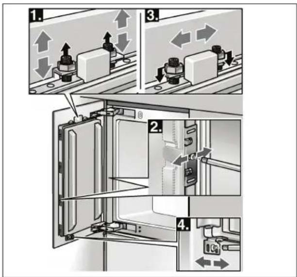
Function of different parts:
- Double threaded bolt on the adjusting rail: for vertical adjustment of the furniture door.
-
Side brackets: for adjusting the depth of the furniture front.
-
Nuts on the double threaded bolt: for securing the furniture front to prevent lateral movement.
- Lower brackets: for securing the furniture front to prevent lateral movement.
Panel unification kit
In the case of 30" and 36" wide appliances 2 adjacent furniture doors can be attached instead of one large door. These furniture doors must be connected to a metal strip on the rear.
This metal strip can be purchased from customer service as an optional accessory, see the section on "Optional accessories" on page 17.
When attaching the metal strip to the furniture doors, observe the maximum possible length of the screws and the position of the drill holes. Always screw into the best load-bearing material of the furniture door.
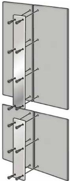
NOTE
- Never screw into fillers, decorative strips or similar.
- If only one furniture door is to be attached to the door of a 30" or 36" wide appliance, attach the supplied sandwich plate to the adjusting rail and lock into position.
20. Loading the appliance door
When attaching the furniture doors, it is recommended to load the door storage compartments in the appliance with weights in order to ensure that the gap width is as precise as possible.
Recommendations:
BM 36" (top, 1 door) .55 lbs / 25 kg
BM 36" (bottom) .22 lbs / 10 kg
21. Attaching the adjusting rail to the furniture door (refrigerator compartment)
NOTE
The adjusting rail is the most important means of adjusting the furniture front.

- Unscrew the installation support part from the appliance door.
NOTE
Store the positioning aids, there will be used in an installation step later.
- Remove the cover plate from the freezer compartment door.

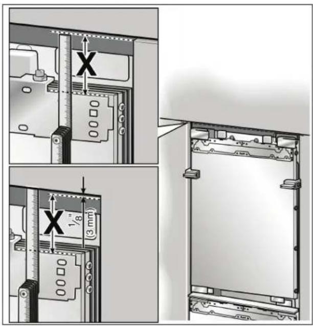
Measure the distance X between the adjusting rail and the overhead furniture/fixtures.
- Loosen the 2 nuts and remove the adjusting rail.
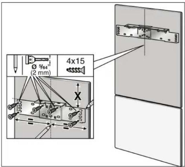
Mark this amount X on the rear of the furniture door.
Determine and mark the centerline of the furniture door.
- Put on the adjusting rail and align along the marks. Mark the drill holes.
- Drill the holes.
- Screw on the adjusting rail tightly.
Notes:
- Attach the adjusting rail to the furniture door with at least 10 screws. One screw should be inserted under each double threaded bolt.

- The adjusting rail features a variety of holes for the many different design options of furniture doors. Always screw into the best load-bearing material of the furniture door.
22. Attaching and aligning the furniture door (refrigerator compartment)
- Hang the furniture door on the double threaded bolt.

- Align the furniture door with the double threaded bolts (Torx screwdriver).
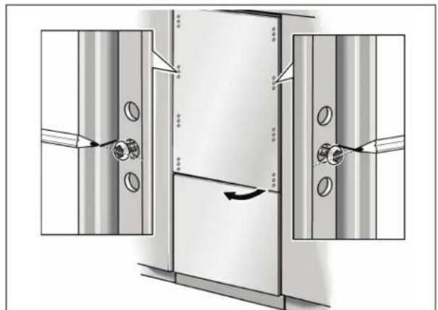
-
Transfer the middle drill holes along the outer edge of the appliance door to the furniture front and mark.
-
Remove the furniture door.
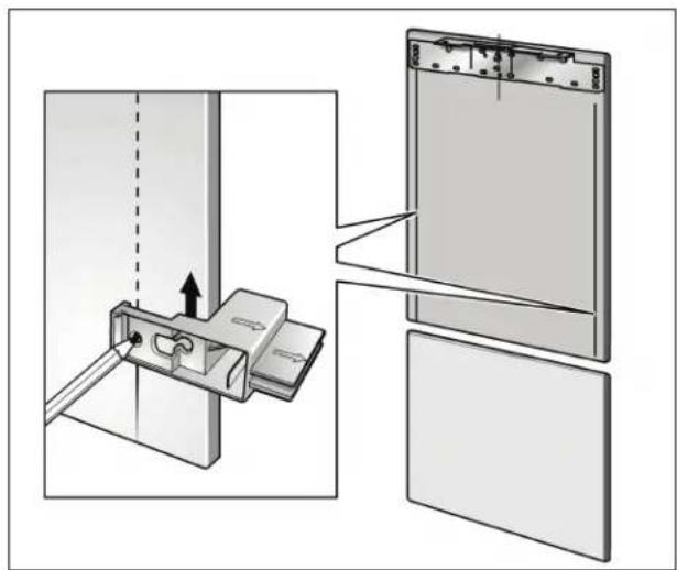
- Using the positioning aid, set both longitudinal sides of the furniture door parallel.
Using a square, extend the drill hole marks which you have just made to the vertical marks.
Apply the fixing rib and mark out the holes.
Pre-drill the holes..
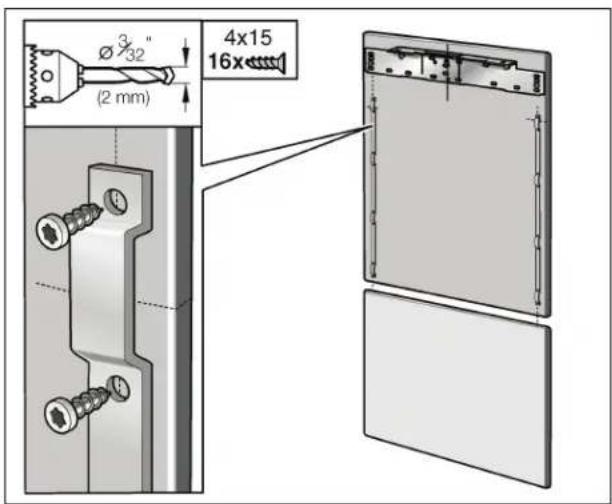
- Screw on the fixing ribs.
- Hang the furniture door on the double threaded bolts.
23. Attaching the adjusting rail to the furniture door (freeze compartment)
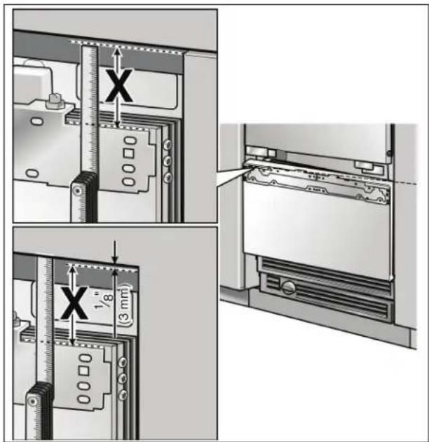
Measure the distance x between the adjusting rail and the overhead furniture/fixtures.
- Loosen the 2 nuts and remove the adjusting rail.
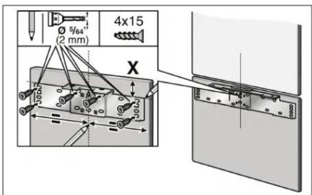
Mark this amount X on the rear of the furniture door.
Determine and mark the centerline of the furniture door.
- Put on the adjusting rail and align along the marks. Mark the drill holes.
- Drill the holes.
Screw on the adjusting rail tightly.

Notes:
- Attach the adjusting rail to the furniture door with at least 10 screws. One screw should be inserted under each double threaded bolt.


- The adjusting rail features a variety of holes for the many different design options of furniture doors. Always screw into the best load-bearing material of the furniture door.
24. Attaching and aligning the furniture door (freezer compartment)
- Hang the furniture door on the double threaded bolt.
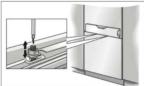
- Align the furniture door with the double threaded bolts (Torx screwdriver).
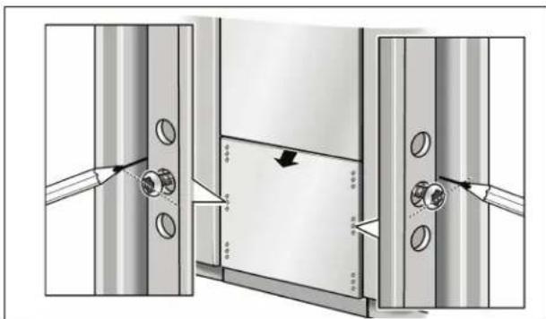
- Transfer the middle drill holes along the outer edge of the appliance door to the furniture front and mark.
- Remove the furniture door.
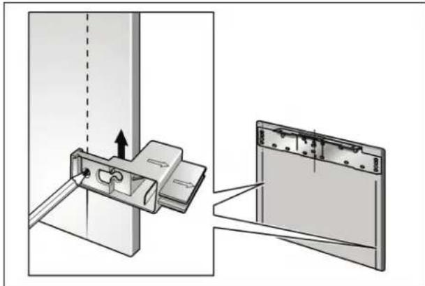
- Using the positioning aid, set both longitudinal sides of the furniture door parallel.
Using a square, extend the drill hole marks which you have just made to the vertical marks.
Apply the fixing rib and mark out the holes.
Pre-drill the holes.
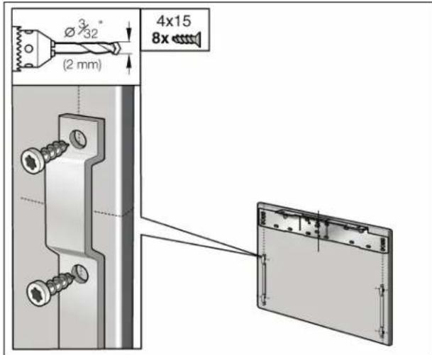
Screw on the fixing ribs.
25. Attaching the furniture door (refrigerator compartment)
NOTE
Now fit the furniture handles which are screwed from behind!
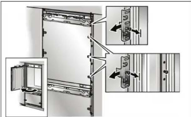
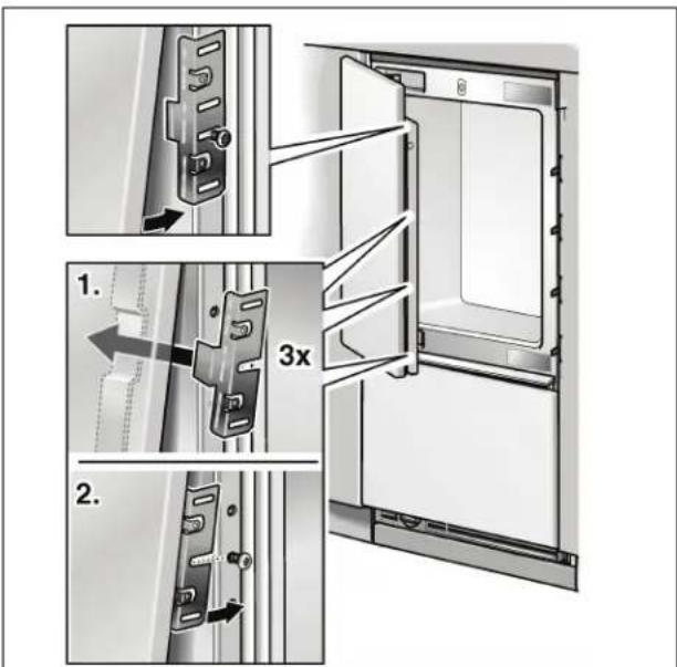
- Remove fixing bracket on the handle side from the appliance door. To do this, loosen the fastening screws only.
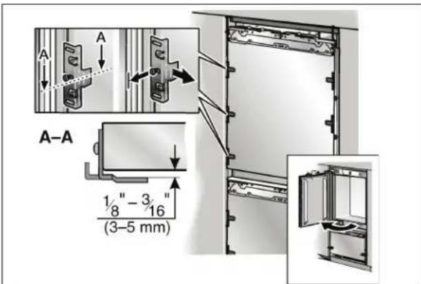
- Loosen fixing bracket on the hinge side and pull slightly off the appliance door. To do this, loosen the fastening screws only.
- Open the appliance door.
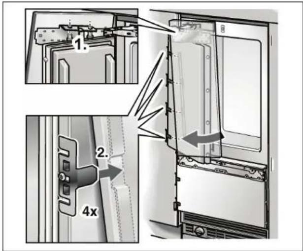
- Hang the furniture door with adjusting rail over the double threaded bolts (1.).
- Raise furniture door slightly and push the fixing rib down over the fixing brackets (2.).
- Insert removed fixing brackets into the fixing rib and push over the fastening screws.
- Screw the nuts a little onto the double threaded bolts. Do not tighten!


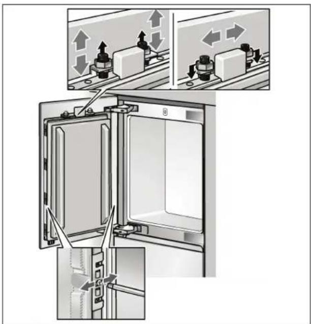
- Adjust the furniture door using the threaded rod (Torx screwdriver). Re-examine the dimensions of the crack continuously.
- Close the door and check that the depth of the furniture front is aligned with the adjacent fronts. If required, correct.
- Tighten the bracket screws to fix the depth alignment.
- Close the door and check the side alignment. Correct by gently tapping the edge of the open furniture door with your hand.

- Tighten the nuts on the adjusting rail. This will fix the side alignment of the door.
26. Attaching the furniture door (freeze compartment)
NOTE
Now fit the furniture handles which are screwed from behind!
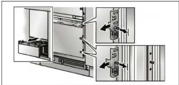
- Remove fixing bracket from one side of the drawer. To do this, loosen the fastening screws only.
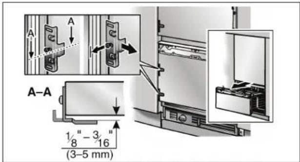
- Loosen fixing bracket on the other side of the drawer and pull slightly off the appliance door. To do this, loosen the fastening screws only.
- Open drawer.
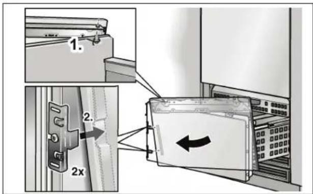
-
Hang the furniture door with adjusting rail over the double threaded bolts (1.).
-
Raise furniture door slightly and push the fixing rib down over the fixing brackets (2.).
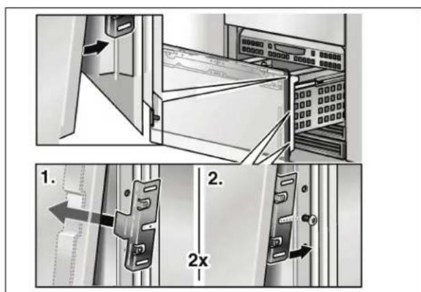
- Insert removed fixing brackets into the fixing rib and push over the fastening screws.
- Screw the nuts a little onto the double threaded bolts. Do not tighten!
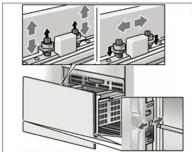
- Adjust the furniture door using the threaded rod (Torx screwdriver). Re-examine the dimensions of the crack continuously.
- Close the door and check that the depth of the furniture front is aligned with the adjacent fronts. If required, correct.
- Tighten the bracket screws to fix the depth alignment.
- Close the door and check the side alignment. Correct by gently tapping the edge of the open furniture door with your hand.
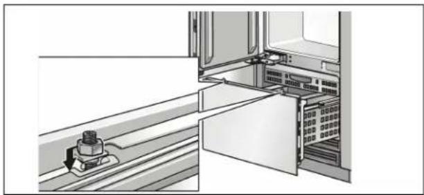

- Tighten the nuts on the adjusting rail. This will fix the side alignment of the door.
27. Attaching the lower bracket
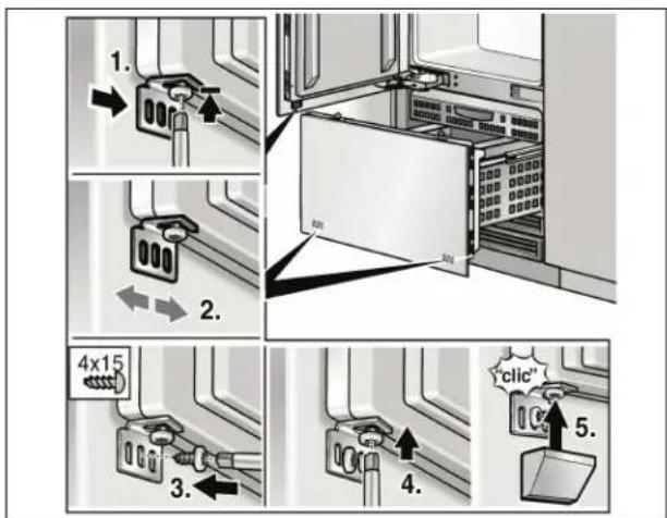
- Screw on the lower brackets (Installation kit).
- Predrill holes in the furniture door!
-
The lower bracket fixes the side position of the door.
-
Loosen the screw.
- Check the side position of the door.
- Screw in the wooden screw.
- Tighten the screw.
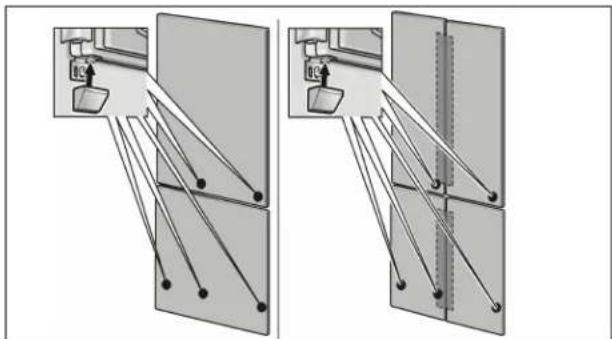
- Put the cover on the brackets.
The number of lower brackets depends on the width and the design of the furniture door.
28. Attaching the finger guard
- Hold the finger guard on the door so that the fixing holes in the cover strip are in alignment with the bores in the fixing brackets.
Now mark the lower edge of the finger guard and shorten accordingly.

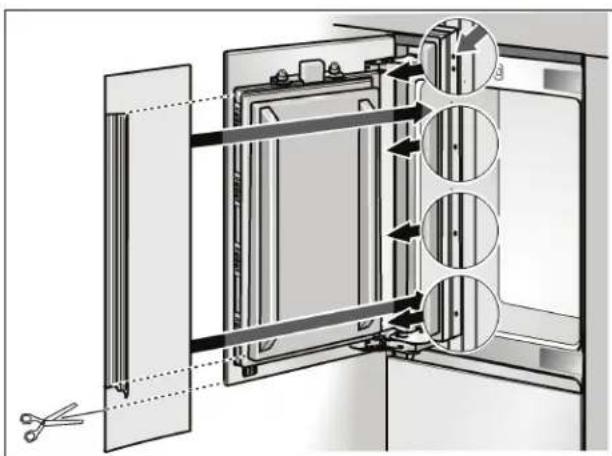
- Insert finger guard into the gap between appliance and cavity wall (1.).
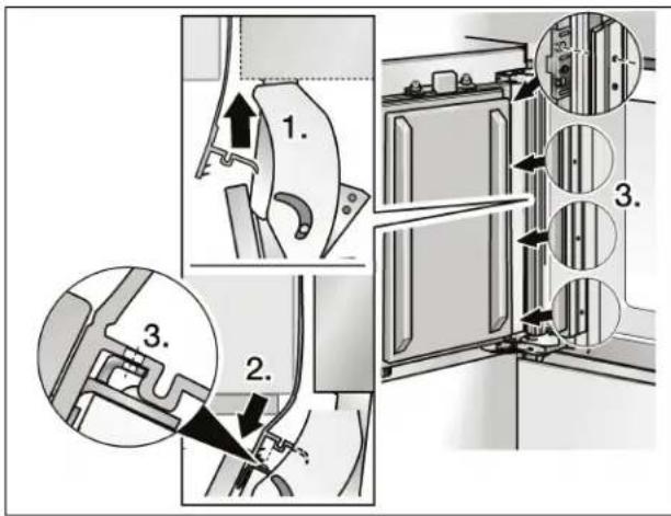
Press cover strip of the finger guard from top to bottom into the gap between the furniture front and appliance door (2.). Ensure that the fixing holes in the cover strip are in alignment with the bores in the fixing brackets (3).!
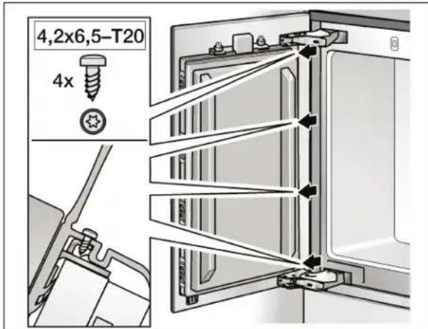
- Attach finger guard to the fixing brackets using the screws.
- Check function and ease of movement of the finger guard by opening and closing the door several times.
29. Attaching the covers
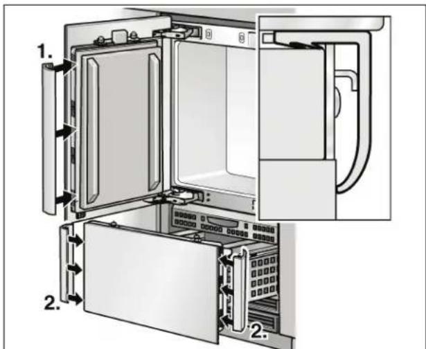
- Place the cover strips on both sides of the door.
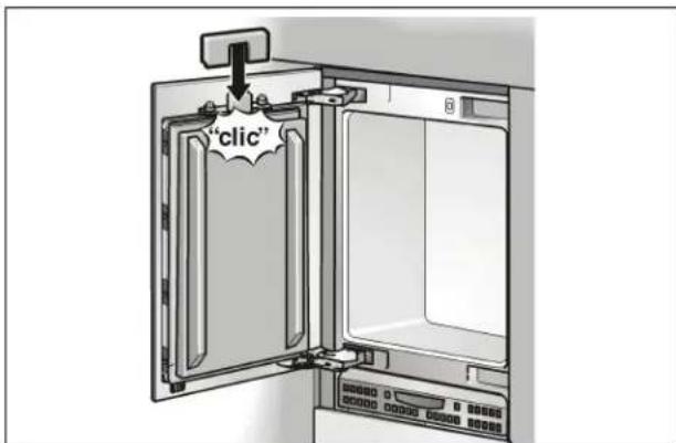
- Attach the light switch cover. The cover can be screwed to the door.
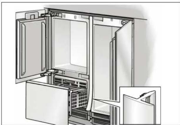
Side-by-Side installation only:
- Insert the cover strip into the space between the appliances.
The cover rail is included in the installation accessories for side-by-side installation.
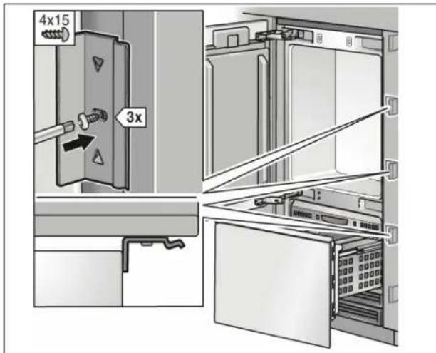
Individual appliances only:
A A p p l i a n c e B Furniture
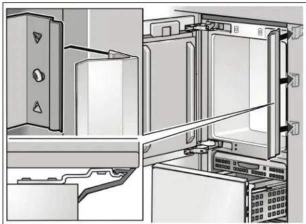
- Screw on the brackets (side) for holding the cover strip.
- Attach the cover ribs to the fastening plates and the brackets (side).
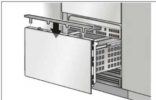
- Insert the cover plate on the freezer compartment door.

30. Mounting of air separator
Screw the air separator to the furniture door in order to separate the supply and waste air.

31. Adjusting the door opening angle
Depending on the installation situation, it may be necessary to adjust the door opening angle. A door opening angle of 115^ has been set at the factory.
To adjust the door opening angle to 90^ :
- Open door to 90^ .
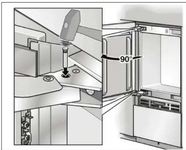
- Insert the banking pin through the boreholes which are now vertically aligned and drive in with a hammer.
32. Changing the door spring

- Rotate the adjusting screw with a cross-head screwdriver.
I = maximum spring tension
0 = no spring tension
Installation of the appliance is now complete.
Sommaire
Installation room 44
C = 24" (610 mm) minimum
2. Transport of the appliance
Panel unification kit
- Attach the base panel to the appliance.
En el caso de electrodomesticos de 30" y 36" de ancho,SEOSEOSEOSEOSEOSEOSEOSEOSEOSEOSEOSEOSEOSEOSEOSEOSEOSEOSEOSEOSEOSEOSEOSEOSEOSEOSEOSEOSEOSEOSEOSEOSEOSEOSEOSEOSEOSEOSEOSEOSEOSEOSEOSEOSEOSEOSEOSEOSEOSEOSEOSEOSEOSEOSEOSEOSEOSEOSEOSEOSEOSEOSEOSEOSEOSEOSEOSEOSEOSEOSEOSEOSEOSEOSEOSEOSEOSEOSEOSEOSEOSEOSEOSEOSEOSEOSEOSEOSEOSEOSEOSEOSEOSEOSEOSEOSEOSEOSEOSEO SEOEO SEOEO SEOEO SEOEO SEOEO SEOEO SEOEO SEOEO SEOEO SEOEO SEOEO SEOEO SEOEO SEOEO SEOEO SEOEO SEOEO SEOEO SEOEO SEOEO SEOEO SEOEO SEOEO SEOEO SEOEO SEOEO SEOEO SEOEO SEOEO SEOEO SEOEO SEOEO SEOEO SEOEO SEOEO SEOEO SEOEO SEOEO SEOEO SEOEO SEOEO SEOEO SEOEO SEOEO SEOEO SEOEO SEOEO SEOEO SEOEO SEOEO SEOEQ
Subject to alterations.
