
SNCHMX70 - Surveillance Camera SONY - Free user manual and instructions
Find the device manual for free SNCHMX70 SONY in PDF.
| Product Type | Network surveillance camera |
| Brand | Sony |
| Model | SNC-HMX70 |
| Maximum resolution | 1920 x 1080 (Full HD) |
| Video compression | H.264, M-JPEG |
| Power supply | PoE (Power over Ethernet) IEEE 802.3af |
| Power consumption | Approximately 12 W |
| Dimensions (L x H x D) | Approximately 150 x 70 x 70 mm |
| Weight | Approximately 1.2 kg |
| Local storage | SD card slot (up to 256 GB) |
| Video content analysis (VCA) | Motion detection, sabotage, intrusion |
| Audio | Audio input/output, AAC compression, G.711 |
| Network | Ethernet 10/100 Base-T, IPv4/IPv6, DHCP, SNMP, QoS |
| Streaming protocols | RTSP, HTTP, FTP |
| Security | Password protection, SSL/TLS encryption, IP filtering |
| Maintenance and cleaning | Clean the lens with a soft, dry cloth. Avoid solvents. |
| Spare parts and repairability | Compatible SD cards. For repair, contact an authorized Sony center. |
| Operating temperature | 0°C to 40°C |
| Warranty | 2 years (according to applicable legislation) |
| General information | Fixed IP camera for indoor/outdoor surveillance, compatible with video management systems. |
Frequently Asked Questions - SNCHMX70 SONY
User questions about SNCHMX70 SONY
0 question about this device. Answer the ones you know or ask your own.
Ask a new question about this device
Download the instructions for your Surveillance Camera in PDF format for free! Find your manual SNCHMX70 - SONY and take your electronic device back in hand. On this page are published all the documents necessary for the use of your device. SNCHMX70 by SONY.
USER MANUAL SNCHMX70 SONY
Table of contents 49
es español
Contedio 98
fr français
Table des matieres 143
ja 口本語
目次 188
ru ycckn
Copepkanhe 229
Inhaltsverzeichnis
-Stream1
-Stream2
Nur I-Frames
Alarmaufzeichnung
-Stream1
-Stream2
Nur I-Frames
4.5.5 Alarm Task Editor
Copyright 1988, 1994 Digital Equipment Corporation.
Permission to use, copy, modify, distribute and sell this software and its documentation for any purpose and without fee is hereby granted, provided that the above copyright notices appear in all copies and that both those copyright notices and this permission notice appear in supporting documentation, and that the names of Adobe Systems and Digital Equipment Corporation not be used in advertising or publicity pertaining to distribution of the software without specific, written prior permission.
This software is based in part on the work of the Independent JPEG Group.
1.1 System requirements 51
1.2 Establishing connection 51
1.3 Password Network 51
2 System overview 52
2.1 Live page 52
2.2Playback 52
2.3 Configuration 52
3 Operation via the browser 53
3.1 Live page 53
3.2Playback page 56
3.2.1 Selecting the recording stream 56
3.2.2 Searching for recorded video 56
3.2.3 Exporting recorded video 56
3.2.4 Track List 57
3.2.5 Controlling playback 57
4 Configuration 58
4.1 General 58
4.1.1 Identification 58
4.1.2 User Management 58
4.1.3 Date/Time 59
4.1.4 Display Stamping 60
4.2 Web Interface 61
4.2.1 Appearance 61
4.2.2 'Live' Functions 63
4.3 Camera 64
4.3.1 Installer Menu 64
4.3.2 Scene mode 68
4.3.3 Color 69
4.3.4 ALC 70
4.3.5 Enhance 71
4.3.6 Scene Mode Scheduler 72
4.3.7 Encoder Profile 73
4.3.8 Encoder Streams 74
4.3.9 Encoder Statistics 75
4.3.10 Encoder Regions 75
4.3.11 Privacy Masks 75
4.3.12 Exposure priority 76
4.3.13 Audio 76
4.3.14 Pixel Counter 77
4.4 Recording 77
4.4.1 Storage Management 77
4.4.2 Recording Profiles 78
4.4.3 Maximum Retention Time 79
4.4.4 Recording Scheduler 79
4.4.5 Recording Status 80
4.4.6 Recording Statistics 80
4.4.7 SD Card Status 80
4.5 Alarm 81
4.5.1 Alarm Connections 81
4.5.2 Video Content Analysis (VCA) 82
4.5.3 Audio Alarm 86
4.5.4 Alarm E-Mail 86
4.5.5 Alarm Task Editor 87
4.6 Interfaces 88
4.6.1 Alarm Inputs 88
4.6.2 Alarm Outputs 88
4.7 Network 88
4.7.1 Network Services 89
4.7.2 Network Access
4.7.3 Advanced
4.7.4 Network Management
4.7.5 Multicast
4.7.6 Image Posting
4.7.7 Accounts
4.7.8 IPv4 Filter
4.8 Service
4.8.1 Maintenance
4.8.2 Licences
4.8.3 Certificates
4.8.4 Logging
4.8.5 System Overview
1 Browser connection
A computer with Microsoft Internet Explorer is used to receive live images, control the unit, and replay stored sequences. The unit is configured over the network using the browser.
1.1 System requirements
Our recommendations are:
- Computer with Dual core HyperThreading processor or better
- Graphic card with performance that matches or is better than the resolution of the camera
- Windows 7 or later operating system
- Network access
- Internet Explorer version 11 or later
Note:
To see live images in your browser it might be necessary to download and install the MPEGActiveX from the download store, available at https://downloadstore.boschsecurity.com.
1.2 Establishing connection
The unit must have a valid IP address to operate on your network and a compatible subnet mask.
By default, DHCP is pre-set at the factory to On plus Link-Local so a DHCP server assigns an IP address or, if no DHCP server is available, a link-local address (auto-IP) is assigned within the range 169.254.1.0 to 169.254.254.255.
- Start the Web browser.
- Enter the IP address of the unit as the URL.
- During initial installation, confirm any security questions that appear.
Note:
If you cannot connect, the unit may have reached its maximum number of connections.
Depending on the device and network configuration, each unit can have up to 50 web browser connections).
Password protection in camera
The device is password protected across various authorization levels. It is necessary to set a password before accessing the device:
- Enter the user name.
- Enter the password. The password should:
- Be between 8 and 12 characters in length
- Contain upper and lower case letters
- Contain a minimum of one special character. These special characters are not allowed: \& ,\& ,\& ,\& ,\& ,\& ,
- Contain a minimum of one digit.
- Click OK. If the password is correct, the page is shown.
1.3 Password Network
If a RADIUS server is used for network access control (802.1x authentication), the unit must be configured first. To configure the unit, connect it directly to a computer using a network cable and configure the two parameters, Identity and Password. Only after these have been configured can communication with the unit via the network occur.
2 System overview
When a connection is established, the Live page is initially shown.
The application bar shows these icons:
| Live | Live To view the live video | stream, click this icon. |
| Playback | Playback To play back re-corded sequences, click this icon. This link is only visible if a storage medium has been configured for recording. (With VRM recording this option is not active.) | |
| Configuration | Configuration To configre the unit, click this icon. | |
| Dashboard | Dashboard To see detailed system information, click this icon. | |
| To get context sensitive help for a particular page, click this icon. | ||
2.1 Live page
The Live page is used to display the live video stream and control the unit.
2.2Playback
The Playback page is used for playing back recorded sequences.
2.3 Configuration
The Configuration page is used to configure the unit and the application interface.
Making Changes
Each configuration screen shows the current settings. You can change the settings by entering new values or by selecting a predefined value from a list field.
Not every page has a Set button. Changes to pages without a Set button are set immediately. If a page does show a Set button, you must click the Set button for a change to take effect.

Notice!
Save each change with the associated Set button.
Clicking the Set button saves the settings only in the current field. Changes in any other fields are ignored.
Some changes only take effect after the unit is rebooted. In this case, the Set button changes to Set and Reboot.
- Make the desired changes.
- Click the Set and Reboot button. The camera reboots and the changed settings are activated.
3 Operation via the browser
3.1 Live page
After the connection is established, the Live page is initially displayed. It shows the live video image on the right of the browser window. Depending on the configuration, various text overlays may be visible on the live video image.
Other information may also be shown next to the live video image. The items shown depend on the settings on the 'Live' functions page.
Connection
In the Connection group, there are three options: Video, Dewarping and Stream.
Video
(Only applicable to SNC-HMX cameras)
If the application variant is set to DEWARP, you can select one of the three available video channels for viewing:
-
On the left side of the browser, expand the Connection group if necessary.
-
Click Video to see the options.
-
By default these are named Full Image Circle (video 1), Dewarped view mode (video 2), and E-PTZ (video 3). These names can be changed in the Configuration >> General >> Identification menu.
-
Select the video channel you wish to view.
If Dewarped view mode or E-PTZ are selected, the Dewarping drop-down list is set to E-PTZ and cannot be changed.
Dewarping
(Only applicable to SNC-HMX cameras)
In the Dewarping drop-down list, select one of the options:
-Off
-E-PTZ
- Panoramic: One panoramic image is shown.
Double panoramic: Two independent panoramic images are shown. They can be adjusted independently on the Live preview. - Corridor: Two independent corridor images are shown. They can be adjusted independently on the Live preview.
- Quad: Four independent panoramic images are shown. They can be adjusted independently on the Live preview.
Image selection
To view a live stream:
- On the left side of the browser, expand the Connection group if necessary.
- Click the Stream drop-down arrow to see the options.
- Select the stream you wish to view.
ROI
(Only applicable to SNC-HMX cameras)
If the Application variant is set to DEWARPED, the ROI group is available.
When the Dewarping drop-down list is set to E-PTZ or Panoramic, the ROI group can be used.
With a dwarped or E-PTZ view, a Region Of Interest (ROI) can be selected.
- On the left side of the browser, expand the ROI group if necessary.
- Use the controls to move around the image.
- Click + to zoom and - to zoom out.
Pre-Positions
Six pre-position files can be defined for views generated by the region of interest (ROI) controls.
- On the left side of the browser, expand the Pre-positions group if necessary.
-
Use the ROI controls to define a particular view.
-
To store this view, click the icon of one of the six pre-position buttons.
-
If a pre-position is already stored, a dialog box displays a message. Click OK to overwrite or Cancel to cancel the operation
-
To recall a stored pre-position, click a pre-position button.
Image orientation
(Only applicable to SNC-HMX cameras)
With dewarping on, you can manipulate the image with the mouse.
- Place the cursor within the image.
- Click an arrow to orientate the image.
- Use the scroll wheel to zoom in and out.
To see the correct orientation of the image, ensure that the mount position and height have been filled-in correctly in Configuration >> Camera >> Installer menu >> Positioning.
Digital I/O
(Only applicable to SNC-EMX cameras)
Depending on the configuration of the unit, the alarm input and the output are displayed next to the image. Expand the Digital I/O group if necessary.
The alarm symbol is for information and indicates the status of an alarm input:
- The symbol lights when the input alarm is active.
The alarm output allows the operation of an external device (for example, a light or a door opener).
-
To activate the output, click the checkmark symbol.
-
The symbol lights when the output is activated.
Recording status

The hard drive icon below the live camera image changes during an automatic recording. The icon lights up and displays a moving graphic to indicate a running recording. If no recording is taking place, a static icon is displayed.
Full-screen display

Click the full-screen icon to view the selected stream in full-screen mode; press Esc on the keyboard to return to the normal viewing window.
Saving snapshots
Individual images from the displayed live video stream can be saved locally in JPEG format on the computer's hard drive. The storage location depends on the configuration of the camera.

- Click the photo camera icon to save a single image.
Recording live video
Video sequences from the displayed live video stream can be saved locally on the computer's hard drive. The sequences are recorded at the resolution specified in the encoder configuration. The storage location depends on the configuration of the camera.

- Click the recording icon to record video sequences.
- Saving begins immediately. The red dot on the icon indicates that a recording is in progress.
- Click the recording icon again to stop recording.
Show latest event

Click the Show latest event icon to watch the last recorded important events.
The Playback page opens.
Storage, CPU and network status


When accessing the unit with a browser, the local storage, processor and network status icons are shown in the upper right of the window.
When a local storage card is available, the memory card icon changes color (green, orange or red) to indicate the local storage activity. If you hover over this icon with the mouse the storage activity is shown as a percentage.
If you hover over the middle icon, the CPU load is shown.
If you hover over the right-hand icon, the network load is shown.
This information can help with problem solving or when fine tuning the unit. For example:
- if the storage activity is too high, change the recording profile,
- if the CPU load is too big, change the VCA settings,
- if the network load is too big, change the encoder profile to reduce bitrate.
Status icons
Various overlays in the video image provide important status information. The overlays provide the following information:

Decoding error
The frame might show artifacts due to decoding errors.

Alarm flag
Indicates that an alarm has occurred.

Communication error
A communication error, such as a connection failure to the storage medium, a protocol violation or a timeout, is indicated by this icon.

Gap
Indicates a gap in the recorded video.

Watermark valid
The watermark set on the media item is valid. The color of the check mark changes according to the video authentication method that has been selected.

Watermark invalid
Indicates that the watermark is not valid.

Motion alarm
Indicates that a motion alarm has occurred.

Storage discovery
Indicates that recorded video is being retrieved.
3.2Playback page
Click Playback in the application bar to view, search or export recordings. This link is only visible when a memory card is configured for recording (with Video Recording Manager (VRM) recording this option is not active).
On the left side of the screen, there are four groups:
- Connection
-Search - Export
- Track list
3.2.1 Selecting the recording stream
On the left side of the browser, expand the Connection group if necessary.
To view a video channel:
- Select the Video option. If Dewarped view mode or E-PTZ are set, the Dewarping dropdown list is set to E-PTZ and cannot be changed. Dewarped video options are only applicable to SNC-HMX cameras.
- Select the Dewarping option.
- Select Recording stream 1 or 2.
3.2.2 Searching for recorded video
On the left side of the browser, expand the Search group if necessary.
- To limit the search to a particular time range, enter the date and times for the start and stop points.
- Select an option from the drop-down box to define a search parameter.
- Click Search.
- The results are shown.
- Click a result to play it back.
- Click Back to define a new search.
3.2.3 Exporting recorded video
On the left side of the browser, expand the Export group if necessary.
- Select a track in the track list or in the search results (or click on the timeline below the video window and drag the buttons to mark the sequence you want to export).
- The start and stop date and time are filled-in for the selected track. If required, change the times.
- In the Time lapse drop-down box, select the original or a condensed speed.
- In the Location drop-down box, select a target.
- Click Export to save the video track.
Note:
The target server address is set on the Network / Accounts page.
3.2.4 Track List
The Track list shows all the available recordings.
3.2.5 Controlling playback
The time bar below the video image allows quick orientation. The time interval associated with the sequence is displayed in the bar in gray. Arrows indicate the position of the image currently being played back within the sequence.
The time bar offers various options for navigation in and between sequences.
- If required, click in the bar at the point in time at which the playback should begin.
- Change the time interval displayed by clicking the plus or minus icons or use the mouse scroll wheel. The display can span a range from six months to one minute.
- Click the alarm jump buttons to go from one alarm event to the next or to the previous one. Red bars indicate the points in time where alarms were triggered.
Controls
Control playback by means of the buttons below the video image.
The buttons have the following functions:
- Start/Pause playback
- Select the playback (forward or backward) speed using the speed regulator
- Step forward or backward frame-by-frame when paused (small arrows)
4 Configuration
4.1 General
4.1.1 Identification
Device name
Assign a unique name to assist in identification. This name simplifies the management of multiple devices in more extensive systems.
The name is used for remote identification, for example, in the event of an alarm. Choose a name that makes it as easy as possible to identify the location unambiguously.
Device ID
Each device should be assigned a unique identifier that can be entered here as an additional means of identification.
Each video channel can be given a name. Click the + sign to add an extra line.
Click Set to apply the changes.
4.1.2 User Management
A password prevents unauthorized access to the device. You can use different authorization levels to limit access.
Proper password protection is only guaranteed when all higher authorization levels are also protected with a password. Therefore, you must always start from the highest authorization level when assigning passwords.
You can define and change a password for each authorization level if you are logged into the "service" user account.
Authentication modes
The section Authentication modes provides information about the authentication modes set in the camera. A checkmark appears in the checkbox to the left of the mode if the mode is set. If the mode is not set, the phrase "No certificate installed" appears to the right of the modename.
This device has three authentication modes:
- Password indicates a password is set for the camera. It prevents unauthorized access to the device, and can use different authorization levels to limit access.
Proper password protection is only guaranteed when all higher authorization levels are also protected with a password. Therefore, you must always start from the highest authorization level when assigning passwords.
You can define and change a password for each authorization level if you are logged into the service user account. - Certificate. A check mark in this check box indicates that at least one certificate is loaded onto the device.
- Active Directory server (AD FS). A check mark in this check box indicates that the device uses an active directory server.
Creating a new user
To create a new user, click Add in the section below Authentication modes.
In the box User, fill in the fields:
- User name: Enter a name with a minimum of 5 and a maximum of 31 characters.
-
Group, select the appropriate authorization level:
-
live is the lowest authorization level. At this level, it is only possible to view the live video image, and switch between the different live image displays.
-
user is the middle authorization level. At this level, it is possible to operate the device and playback recordings, but configuration changes are not possible.
- service is the highest authorization level. Entering the correct password gives access to all the functions, and allows all configuration settings to be changed.
3. Type, select either:
- Password for a new password.
Use a minimum of 6 and a maximum of 19 characters. The password must have upper-case and lower-case letters, one or more numerical digits and one or more of these special characters ! ?" # $ % ( ) { } [ ] * + - = . , ; ^ _ | ~ \Special characters such as space @ : < > ' & are not valid. In this case, enter the new password a second time to eliminate typing mistakes.
- Certificate for a certificate that the new user is authorized to use.
4.1.3 Date/Time
Date format
Select the required date format.
Device date/Device time
If there are multiple devices operating in your system or network, it is important to synchronize their internal clocks. For example, it is only possible to identify and correctly evaluate simultaneous recordings when all devices are operating on the same time.
- Enter the current date. Since the device time is controlled by the internal clock, it is not necessary to enter the day of the week - it is added automatically.
- Enter the current time or click Sync to PC to apply the system time from your computer to the device.
Note:
It is important that the date/time is correct for recording. An incorrect date/time setting could prevent correct recording.
Device time zone
Select the time zone in which the system is located.
Daylight saving time
The internal clock can switch automatically between normal and daylight saving time (DST). The unit already contains the data for DST switch-overs for many years in advance. If the date, time and zone have been set up correctly, a DST table is automatically created. If you decide to create alternative daylight saving time dates by editing the table, note that values occur in linked pairs (DST start and end dates).
First, check the time zone setting. If it is not correct, select the appropriate time zone and click Set.
- Click Details to edit the DST table.
- Select the region or the city which is closest to the system's location from the list box below the table.
- Click Generate to fill the table with the preset values from the unit.
- Click one of the entries in the table to make changes. The entry is highlighted.
- Click Delete to remove the entry from the table.
-
Choose other values from the list boxes under the table, to change the selected entry. Changes are immediate.
-
If there are empty lines at the bottom of the table, for example after deletions, add new data by marking the row and selecting values from the list boxes.
- When finished, click OK to save and activate the table.
Time server address
The unit can receive the time signal from a time server using various time server protocols and then use it to set the internal clock. The device polls the time signal automatically once every minute.
Enter the IP address of a time server.
Overwrite by DHCP
Select this checkbox to have the DHCP server give the time server date.
Time server type
- Select Time protocol if the server uses the RFC 868 protocol.
- Select the protocol that is supported by the selected time server. It is recommended to select the SNTP protocol protocol. This protocol provides high accuracy and is required for special applications and future function extensions.
- Select the TLS protocol if the server uses the RFC 5246 protocol.
Click Set to apply the changes.
4.1.4 Display Stamping
Various overlays or stamps in the video image provide important supplementary information. These overlays can be enabled individually and arranged on the image in a clear manner.
Camera name stamping
Select the position of the camera name overlay in the drop-down box. It can be displayed at the Top, at the Bottom, or at a position of choice using the Custom option, or it can be set to Off for no overlay information.
If the Custom option is selected, enter values in the X and Y position fields.
Logo
To place a logo on the image, select and upload an uncompressed .bmp file with a maximum size of 128x128 pixels and 256 colors to the camera. Its position on the image can then be selected.
Logo position
This option becomes available when the Camera name stamping option is enabled. Select:
-
Off : This option is disabled.
-
To the left of the name: The logo will be positioned to the left of the Camera name stamping
- To the right of the name: The logo will be positioned to the right of the Camera name stamping
- Logo only: The logo will be shown without the Camera name stamping.
Time stamping
Select the position of the time and date overlay in the drop-down box. It can be displayed at the Top, at the Bottom, or at a position of choice using the Custom option, or it can be set to Off for no overlay information.
If the Custom option is selected, enter values in the X and Y position fields.
Display milliseconds
If necessary, display milliseconds for Time stamping. This information can be useful for recorded video images; however, it does increase the processor's computing time. Select Off if displaying milliseconds is not needed.
Alarm mode stamping
Select On in the drop-down box for a text message to be displayed in the event of an alarm. It can be displayed at a position of choice using the Custom option, or it can be set to Off for no overlay information.
If the Custom option is selected, enter values in the X and Y position fields.
Alarm message
Enter the message to be displayed on the image in the event of an alarm. The maximum text length is 31 characters.
Transparent background
Check this box to make transparent the stamp background on the image.
Video authentication
Select from the Video authentication drop-down box a method for verifying the integrity of the video.
If you select Watermarking, all images are marked with an icon. The icon indicates if the sequence (live or saved) has been manipulated.
If you want to add a digital signature to the transmitted video images to ensure their integrity, select one of the cryptographic algorithms for this signature.
Signature interval [s]
For certain Video authentication modes, enter the interval (in seconds) between insertions of the digital signature.
Click Set to apply the changes.
4.2 Web Interface
4.2.1 Appearance
You can adapt the appearance of the web interface and change the website language to meet your requirements.
GIF or JPEG images can be used to replace the company and device logos. The image can be stored on a web server (for example, http://www.myhostname.com/images/logo.gif).
Ensure that a connection to the web server is always available to display the image. The image files are not stored on the unit.
To restore the original graphics, delete the entries in the Company logo and Device logo fields.
Website language
Select the language for the user interface.
Company logo
To replace the company's logo in the top-right part of the window, enter the path to a suitable image in this field. The image file must be stored on a web server.
Device logo
To replace the device name in the top-left part of the window, enter the path to a suitable image in this field. The image file must be stored on a web server.
Show VCA metadata
When video content analysis (VCA) is activated, additional information is displayed in the live video stream. With the MOTION+ analysis type, for example, the sensor fields in which motion is recorded are marked with yellow rectangles.
Using Essential Video Analytics, the outlines of detected objects are displayed in following colors:
- Red: Objects that generate an alarm event under the current settings appear on the camera image inside a red outline.
- Orange: An object that has triggered one alarm event but does not generate another appears inside an orange outline (example: object has crossed a line). During forensic search, an object that triggers an alarm event has an orange outline from the beginning.
- Yellow: Objects that are detected as moving but do not generate an alarm event under the current settings appear inside a yellow outline.
Show VCA trajectories
When video content analysis (VCA) is activated, check this item to show additional information that traces the path of objects, if the corresponding analysis type provides this data.
Show overlay icons
Select this check box to show overlay icons on the live video image.
Show VCA items
Select this checkbox to show VCA items on the live video image.
Shows alarm fields, lines and routes configured for the video analytics in the following colors:
- Green: Fields, lines and routes used in a task are displayed in green. They can be edited but not deleted.
- Red: Fields, lines and routes currently in alarm mode are displayed in red.
Show ' Dashboard'
Select this checkbox to enable the Dashboard in the application bar.
Secure cookie handling
Select this checkbox to secure the cookies sent through the camera.

Notice!
If cookies are secured, authentication forwarding to MPEG ActiveX and the Video Security App is prohibited.
Latency mode
Select the required latency mode:
- Low delay: Default mode. Provides marginal buffering to display fluent video under normal network conditions.
- Smooth video: Allows the buffer to automatically adjust to cover network jitter, inducing higher latency.
- No buffering: Shows video as it is received by the decoder with minimum latency. Allows the video to jerk if there is network jitter.
Video buffer
The value shown is calculated from the Latency mode setting. It cannot be changed.
JPEG resolution
You can specify the size of the JPEG image on the Live page. Options are Small, Medium, Large, 720p, 1080p, and "Best possible" (default).
JPEG interval
You can specify the interval at which the individual images should be generated for the M-JPEG image on the Live page.
JPEG quality
You can specify the quality at which the JPEG images appear on the Live page.
Click Set to apply the changes.
4.2.2 'Live' Functions
You can adapt the Live page functions to meet your requirements. Choose from a variety of different options for displaying information and controls.
- Select the check boxes for the functions to be displayed on the Live page. The selected elements are checked.
- Check to see if the desired items are shown.
Transmit audio
When selected, the audio from the camera (if set to On on the Audio page) is sent to the computer. This setting applies only to the computer on which the selection is made. Transmitting audio data requires additional network bandwidth.
Lease time [s]
The lease time in seconds determines the time beyond which a different user is authorized to control the camera after no further control signals are received from the current user. After this time interval, the camera is automatically available for another user.
Set a time frame (in minutes) for the automatic logout. Default value is 0 (no automatic logout).
Show alarm inputs
(Only applicable to SNC-EMX cameras)
The alarm inputs are displayed next to the video image as icons along with their assigned names. If an alarm is active, the corresponding icon changes color.
Show alarm outputs
(Only applicable to SNC-EMX cameras)
Alarm outputs are shown next to the video image as icons along with their assigned names. If an output is switched, the icon changes color.
Allow snapshots
Specify whether the icon for saving individual images should be displayed below the live image. Individual images can only be saved if this icon is visible.
Allow local recording
Specify whether the icon for saving video sequences locally should be displayed below the live image. Video sequences can only be saved locally on your hard disk if this icon is visible.
I-frames-only stream
When this checkbox is enabled, the I-frames stream option, on the Connection tab of the Live page is available.
Select to display an additional tab on the Live page where only I-frames can be viewed. Ensure that I-frame quality is not set to Auto or no updates will occur.
Show 'Pre-positions'
Select to display or hide the pre-positions widget on the live page.
Path for JPEG and video files
Enter the path for the storage location of individual images and video sequences saved from the Live page.
Video file format
Select a file format for the live page display. The MP4 format does not include metadata. Click Set to apply the changes.
4.3 Camera
4.3.1 Installer Menu
Application variant
(Only applicable to SNC-HMX cameras)
The camera has a choice of application variants that set up the camera for optimum performance in a specific environment. Select the application variant best suited to your installation.
The application variant must be selected before any other changes are made, as the camera reboots automatically and resets the factory defaults when the application variant is changed.
Sensor mode
Select the sensor mode for the camera.
Note: Shutter times, frame rates, and the analog output (if present) are affected by this value.
Image rotation
(Only applicable to SNC-EMX cameras)
The integrated gyro/accelerometer sensor detects the optimal image orientation and allows the user to select it by clicking Use proposed rotation.
Select the required angle (0^, 90^, 180^ or 270^) to output the correct image orientation.
Mirror image
(Only applicable to SNC-EMX cameras)
Select On to output a mirror image of the camera picture.
Coding standard
(Only applicable to SNC-EMX cameras)
Select the coding standard, H.264, H.265, or H.265 (no B-frames). (H.265 (no B-frames) is only applicable to SNC-EMX30, EMX30R and EMX32R.)
Camera LED
Disable the Camera LED on the camera to switch it off.
Button'MENU'
(Only applicable to SNC-EMX cameras)
Select Disabled to prevent access to the install wizard via the menu button on the camera itself.
Analog output
(Only applicable to SNC-EMX cameras)
Select an aspect ratio format to activate the analog output of the camera.
Reboot device
Click Reboot to restart the camera.
Factory defaults
Click Defaults to restore the factory defaults for the camera. A confirmation screen appears.
Allow several seconds for the camera to optimize the picture after a reset.
Lens Wizard...
(Only applicable to SNC-EMX cameras)
Click Lens Wizard... to open a separate window which can be used to focus the camera lens. This page enables you to focus the lens on a particular area.
In the preview window, use the mouse to change the size and position of the shaded box that defines the focus area.
Default
(only for cameras with motorized focus adjustment)
Click Default to set the lens to its default position.
Zoom
(only for AVF lenses)
Use the slider to adjust the optical zoom of the lens.
Focus
(only for cameras with motorized focus adjustment)
-
Check the IR-corrected lens box to have the same focus positions for day and night.
-
To adjust the focus position separately for day and night uncheck the IR-corrected lens box. Select the Day/night mode (Color or Monochrome) in the Configuration / Camera / ALC menu; the relevant focus position slider is activated.
-
The lens type is displayed; if applicable, select the lens type.
-
To autofocus the lens click either Full Range or Local Range:
-
The motorized automatic back focus process runs through either the full range or the local range.
-
The focus position, state and indicator are shown.
-
If the IR-corrected lens box is unchecked, select the other Day/night mode and readjust the focus for this mode.
Positioning
The Positioning feature describes the location of the camera and the perspective in the camera's field of view.
Perspective information is essential to Video Analytics, as it enables the system to compensate for the illusory smallness of distant objects.
Only through use of perspective information is it possible to distinguish objects such as persons, bicycles, cars and trucks, and accurately compute their real size and speeds as they move through 3D space.
However, to calculate perspective information accurately, the camera must be directed at a single, flat horizontal plane. Multiple and inclined planes, hills, stairs can falsify perspective information and produce incorrect object information such as size and speed.
Mounting position
The mounting position describes the perspective information that is also often called calibration.
In general, the mounting position is determined by the parameters of the camera such as height, roll angle, tilt angle, and focal length.
The height of the camera must always be entered manually. Whenever possible, roll angle and tilt angle are provided by the camera itself. The focal length is provided, if the camera has a built-in lens.
Select the appropriate mounting position of the camera. Dropout options only applicable to SNC-HMX cameras.
- Ceiling
- Custom
- Wall
Tilt angle [°]
Enter the tilt angle if the value is not determined by the camera.
The tilt angle describes the angle between the horizontal and the camera.
A tilt angle of 0^ means that the camera is mounted parallel to the ground.
A tilt angle of 90^ means that the camera is mounted vertically in bird's eye view perspective.
The flatter the tilt angle is set, the less accurate the estimate of object sizes and speeds will be. The settings must be between 0^ and 90^ . Estimates are no longer possible when you have reached 0^ .
Roll angle [°]
Enter the roll angle if the value is not determined by the camera.
The roll angle describes the angle between the roll axis and the horizontal plane. The angle can deviate from the horizontal by up to 45^ .
Height [m]
Enter the height in meters of the position of the camera.
The height describes the vertical distance from the camera to the ground plane of the captured image. Typically the elevation of the mounted camera above the ground.
Focal length [mm]
(Only applicable to SNC-EMX cameras)
Enter the focal length in millimeters of the position of the camera if the value is not determined by the camera.
The focal length is determined by the lens. The shorter the focal length, the wider the field of view. The longer the focal length, the narrower the field of view and the higher the magnification.
Show sensor values...
(Only applicable to SNC-EMX cameras)
Click to automatically see the camera parameters, for example, Tilt angle [°], Roll angle
[°]and Focal length. These calibration values are measured by the device sensors. Click 'OK' to transfer them to the Positioning settings page.
Sketch
(Only applicable to SNC-EMX cameras)
Click to improve the automatic calibration. The Sketch Calibration window is displayed.
The Sketch functionality offers an additional, half-automatic calibration method. This calibration method allows you to describe the perspective in the camera's field of view by drawing vertical lines, ground lines, and ground angles in the camera image and entering the correct size and angle. Use the Sketch functionality if the result of the automatic calibration is not sufficient.
You can also combine this manual calibration with the values for roll angle, tilt angle, height and focal length calculated by the camera or entered manually.
Select the Calculate check box to obtain the roll angle, tilt angle, height and focal length from the sketched calibration elements - vertical lines, ground lines and angles - you have placed in the camera.
Clear the Calculate check box to enter a value manually or to refresh to the values provided by the camera itself.
Calibrating cameras using the Sketch Calibration window
To determine non-automatically set values:
-
Enter the value for tilt angle, roll angle, height and focal length if the value is known, for example, by measuring the height of the camera above the ground, or reading the focal length from the lens.
-
For each value that is still unknown, select the Calculate check box, then place a calibration element on the camera image. Use these calibration elements to trace individual outlines of the displayed environment in the camera image and define the position and size of these lines and angles.
-
Click to place a vertical line across the image.
A vertical line corresponds to a line that is perpendicular to the ground plane, such as a door frame, edge of a building or a lamp post.
- Click to place a line across the ground in the image.
A line on ground corresponds to a line that is on the ground plane, such as a road marking.
- Click to place an angle on the ground in the image.
The angle on ground represents an angle lying on the horizontal ground plane, such as the corner of a carpet or parking bay markings.
-
Adjust the calibration elements to the situation:
-
Enter the real size of a line or angle. To do this, select the line or angle, then enter the size in the corresponding box.
Example: You have placed a line on ground across the lower side of an automobile. You know that the automobile is 4m long. Enter 4m as the length of the line.
- Adjust the position or length of a line or angle. To do this, drag the line or angle or move the end points to the desired position in the camera image.
- Remove a line or angle. To do this, select the line or angle, then click the trash can icon.
Note:
Blue lines indicate calibration elements added by you.
White lines represent the element as it should be positioned on the camera image based on the current calibration results or the determined calibration data.
Horizon
If the values correspond, areas on the camera image have a colored background.
blue: This area corresponds to the sky. The bottom line of the blue area represents the horizon. Objects that are detected in the blue area cannot be filtered correctly by size or speed.
If the camera is installed at a relatively low height in a building, for example, this display is not required, because the entire area covered by the camera is below the horizon.

Notice!
If the distance to the camera (geolocation) is not relevant, it is enough to determine height and focal length in relation to each other. This allows a simple calibration by marking 2-3 persons - each with a vertical line - and setting their size. 1,80m (71 in.) for all is sufficient. Use at least one person in the front and one person in the background of the image for best results.
Coordinate system
Select the coordinate system and enter the appropriate values in the additional input fields that appear depending on the coordinate system selected.
The Coordinate system feature describes the position of the camera in a local Cartesian or the global WGS 84 coordinate system. The camera and the objects tracked by the video analytics are displayed on a map.
Cartesian
The Cartesian coordinate system describes each point in the space by a combination of the position on three orthogonal axes X, Y and Z. A right-handed coordinate system is used, where X and Y span the ground plane and Z describes the elevation of the ground plane.
X [m]
The location of the camera on the ground on the X-axis.
Y [m]
The location of the camera on the ground on the Y-axis.
Z [m]
The elevation of the ground plane. To determine the elevation of the camera, add the Z [m] value and the Height [m] value of the camera.
WGS 84
The WGS 84 coordinate system is a spherical coordinate system description of the world and used in many standards including GPS.
Latitude
Latitude is the north-south position of the camera in the spherical coordinate system WGS 84.
Longitude
Longitude is the east-west position of the camera in the spherical coordinate system WGS 84.
Ground level [m]
The elevation of the ground above sea level. To determine the elevation of the camera, add the Ground level [m] value and the Height [m] value of the camera.
Azimuth [°]
The orientation of the camera in a counter-clockwise angle starting with 0^ in the east (WGS 84) or on the X-axis (Cartesian). If the camera is directed towards the north (WGS 84) or the Y-axis (Cartesian), the azimuth is 90^ .
Click Set to apply the changes.
4.3.2 Scene mode
A scene mode is a collection of image parameters that are set in the camera when that particular mode is selected (installer menu settings are excluded). Several pre-defined modes are available for typical scenarios. After a mode has been selected, additional changes can be made through the user interface.
Current mode
Select the mode you wish to use from the drop-down menu.
Standard
This mode is optimized for most standard scenes both indoor and outdoor but it avoids the limitations imposed by the sun or street lighting as available in sodium lighting mode.
Sodium lighting
This mode can be used in applications with street (sodium vapor) lighting. A special white balance algorithm compensates for the yellow / orange color of the lights.
Fast movement
This mode is used for monitoring fast moving objects like cars in traffic scenes. Motion artifacts are minimized and the image is optimized for a sharp and detailed picture in color and monochrome. Due to short shutter speeds, a higher light level is needed to ensure optimum results.
Sensitivity boost
This mode provides maximum sensitivity in low light scenes by using longer exposure times, resulting in bright images even in extreme low light. It can introduce motion motion blur because of the slow shutter speed.
Dynamic backlight
In this mode Intelligent Auto Exposure is enabled, it automatically optimizes the exposure for the moving objects in the scene. It's ideal for cameras monitoring an entrance with people moving in front of a bright background.
Vibrant
This mode provides a more vivid image with increased contrast, sharpness and saturation. This is at the expense of slightly reduced color accuracy and higher bit-rate.
Color only
In this mode the camera will not switch to monochrome mode at low light levels. It can be used for scenarios where color images are required day and night, like in city surveillance.
Sports and gaming
This mode is for high-speed capture, and improved color rendition and sharpness.
Retail
This mode has improved color rendition and sharpness with reduced bandwidth requirements.
Mode ID
The name of the selected mode is displayed.
Copy mode to
Select the mode from the drop-down menu to which you wish to copy the active mode.
Click Restore Mode Defaults to restore the factory default modes. Confirm you decision.
4.3.3 Color
Brightness (0...255)
Adjust the brightness with the slider from 0 to 255.
Contrast (0...255)
Adjust the contrast with the slider from 0 to 255.
Saturation (0...255)
Adjust the color saturation with the slider from 0 to 255.
White balance
-
Basic auto mode allows the camera to continually adjust for optimal color reproduction using an average reflectance method. This is useful for indoor light sources and for colored LED light illumination.
-
Standard auto mode allows the camera to continually adjust for optimal color reproduction in an environment with natural light sources.
-
Sodium lamp auto mode allows the camera to continually adjust for optimal color reproduction in an environment with sodium vapor light sources (street lighting).
-
Dominant color auto mode takes into account any dominant color in the image (for example, the green of a football pitch or of a gaming table) and uses this information to obtain a well balanced color reproduction.
- In Manual mode the Red, Green, and Blue gain can be manually set to a desired position.
Hold
Click Hold to put ATW on hold and save the current color settings. The mode changes to manual.
RGB-weighted white balance
In an auto mode, RGB-weighted white balance can be switched On or Off. When On, additional fine tuning of the automatic color reproduction can be made with the R, G and B weight sliders.
R-gain
In Manual white balance mode, adjust the red gain slider to offset the factory white point alignment (reducing red introduces more cyan).
G-gain
In Manual white balance mode, adjust the green gain slider to offset the factory white point alignment (reducing green introduces more magenta).
B-gain
In Manual white balance mode, adjust the blue gain slider to offset the factory white point alignment (reducing blue introduces more yellow).
Note:
It is only necessary to change the white point offset for special scene conditions.
Default
Click Default to set all video values to their factory setting.
4.3.4 ALC
ALC mode
Select the mode for automatic light-level control:
- Fluorescent 50Hz
- Fluorescent 60 Hz
-Standard
ALC level
Adjust the video output level (-15 to 0 to +15).
Select the range within which the ALC will operate. A positive value is more useful for low-light conditions; a negative value is more useful for very bright conditions.
ALC - average vs. peak
(Only applicable to SNC-HMX cameras)
The saturation (av-pk) slider configures the ALC level so that it controls mainly on scene average level (slider position -15) or on scene peak level (slider position +15). Scene peak level is useful for capturing images that contain car headlights.
Exposure
Automatic exposure
Select to let the camera automatically set the optimum shutter speed. The camera tries to maintain the selected shutter speed as long as the light level of the scene permits.
-
Select the Min. frame rate for automatic exposure. (The values available depend on the value set for the Sensor mode in the Installer Menu).
-
Select the Default shutter for automatic exposure. The default shutter improves the motion performance in auto exposure mode.
Fixed exposure
Select the shutter time for fixed exposure. (The values available depend on the value set for the ALC mode).
Day/Night
Auto - the camera switches the IR cut-off filter on and off depending on the scene illumination level.
Monochrome - the IR cut-off filter is removed, giving full IR sensitivity.
Color - the camera always produces a color signal regardless of light levels.
Day-to-night switchover
(Only applicable to SNC-HMX cameras)
Adjust the slider to set the video level at which the camera in Auto mode switches from color to monochrome operation (-15 to +15).
A low (negative) value means that the camera switches to monochrome at a lower light level. A high (positive) value means that the camera switches to monochrome at a higher light level.
Night-to-day switchover
Adjust the slider to set the video level at which the camera in Auto mode switches from monochrome to color operation (-15 to +15).
A low (negative) value means that the camera switches to color at a lower light level. A high (positive) value means that the camera switches to color at a higher light level.
(The actual switch-over point might change automatically to avoid unstable switching.)
Note:
To ensure stability when using IR illuminators, use the alarm interface for reliable Day/Night switching.
IR function
(only for cameras with built-in IR illuminators)
Select the control setting for IR illumination:
-
Auto: the camera automatically switches the IR illumination.
-
On: the IR illumination is always on.
-
Off: the IR illumination is always off.
Intensity level
Set the intensity of the IR beam (0 to 30).
4.3.5 Enhance
High dynamic range
(Only applicable to SNC-EMX50, EMX50R, and EMX52R)
Select:
Off: to disable HDR;
Auto: for automatic High Dynamic Range (HDR); depending on the scene the camera can capture multiple exposures to increase Dynamic Range;
Extreme: as Auto, but with even higher Dynamic Range. Only use this in quiet scenes and low light levels. Artifacts can occur depending on the light level and movement in the scene.

Notice!
Do not use HDR with 50 / 60Hz fluorescent or pulse width modulated LED lighting HDR can only be active if Auto exposure is selected, and there is a match between the base frame rate (selected in the installer menu) and the ALC fluorescent mode frequency. If there is a conflict, a pop-up window will suggest a solution and adjust the appropriate settings.
Backlight compensation
Select Off to switch off backlight compensation.
Select On to capture details in high-contrast and extremely bright-dark conditions.
Select Intelligent AE to capture object detail in scenes with people moving in front of a bright background
Contrast enhancement
Select On to increase the contrast in low contrast conditions.
Intelligent Defog
Select this to activate the automatic intelligent defog feature. This feature continuously adjusts image parameters to provide the best picture possible under foggy or misty conditions.
Sharpness level
The slider adjusts the sharpness level between -15 and +15. Zero position of the slider corresponds to the factory default level.
A low (negative) value makes the picture less sharp. Increasing sharpness brings out more detail. Extra sharpness can enhance the details of license plates, facial features and the edges of certain surfaces but can increase bandwidth requirements.
Intelligent Dynamic Noise Reduction
Select On to activate intelligent Dynamic Noise Reduction (DNR) which reduces noise based on motion and light levels.
Temporal noise filtering
Adjusts the Temporal noise filtering level between -15 and +15. The higher the value, the more noise filtering.
Spatial noise filtering
Adjusts the Spatial noise filtering level between -15 and +15. The higher the value, the more noise filtering.
Intelligent streaming
(Only applicable to SNC-EMX cameras)
The sharpness level, Temporal noise filtering and Spatial noise filtering can be automatically adjusted here, through the encoder, for optimum intelligent streaming results.
Dynamic sharpness & noise filtering
Enable or disable the automatic adjustment of the encoder.
Priority encoder stream
Select stream 1, 2 or smart select as the priority stream for the encoder. The smart select automatically selects the optimum stream.
4.3.6 Scene Mode Scheduler
The scene mode scheduler is used to determine which scene mode should be used during the day and which scene mode should be used during the night.
- Select the mode you wish to use during the day from Marked range drop-down box.
- Select the mode you wish to use during the night from Unmarked range drop-down box.
- Use the two slider buttons to set the Time ranges.
Click Set to apply the changes.
4.3.7 Encoder Profile
Profiles are rather complex and include a number of parameters that interact with one another, so it is generally best to use the pre-defined profiles. Only change a profile if completely familiar with all the configuration options.
Changing a profile
To change a profile, select it by clicking its tab and then change the parameters within that profile.
If a setting outside the permitted range for a parameter is entered, the nearest valid value is substituted when the settings are saved.
Profile name
If required, enter a new name for the profile.
Bit rate optimization
Select the necessary bit rate optimization setting.
Maximum bit rate
The encoder maintains the maximum bit rate over a number of GOPs (group-of-pictures), limiting image quality when necessary. To ensure long-term stability of the maximum bit rate, use the Averaging period.
The value entered in this field must be at least 10% higher than the value entered in the field Target bit rate. If the value entered here is too low, it will be adjusted automatically.
The value in this field is not to be interpreted as the network transmission bit rate.
Averaging period
Select the appropriate averaging period as a means of stabilizing the long term bit rate.
Target bit rate
To optimize use of the bandwidth in the network, limit the data rate for the device. The target data rate should be set according to the desired picture quality for typical scenes with no excessive motion.
For complex images or frequent changes of image content due to frequent movements, this limit can temporarily be exceeded up to the value entered in the Maximum bit rate field.
Encoding interval
The Encoding interval slider determines the interval at which images are encoded and transmitted. This can be particularly advantageous with low bandwidths. The image rate is displayed next to the slider.
Expert Settings
If necessary, use the expert settings to adapt the I-frame quality and the P-frame quality to specific requirements. The setting is based on the H.264 quantization parameter (QP).
I-frame distance
Use the slider to set the distance between I-frames to Auto or to between 3 and 255. An entry of 3 means that every third image is an I-frame. The lower the number, the more I-frames are generated.
Min. P-frame QP
In the H.264-protocol, the Quantization Parameter (QP) specifies the degree of compression and thus the image quality for every frame. The lower the QP value, the higher the encoding quality. A higher quality produces a higher data load. Typical QP values are between 18 and 30. Define the lower limit for the quantization of the P-frames here, and thus the maximum achievable quality of the P-frames.
I/P-frame delta QP
This parameter sets the ratio of the I-frame QP to the P-frame QP. For example, you can set a lower value for I-frames by moving the slide control to a negative value. Thus, the quality of the I-frames relative to the P-frames is improved. The total data load will increase, but only by the portion of I-frames.
To obtain the highest quality at the lowest bandwidth, even in the case of increased movement in the picture, configure the quality settings as follows:
- Observe the coverage area during normal movement in the preview images.
- Set the value for Min. P-frame QP to the highest value at which the image quality still meets your needs.
- Set the value for I/P-frame delta QP to the lowest possible value. This is how to save bandwidth and memory in normal scenes. The image quality is retained even in the case of increased movement since the bandwidth is then filled up to the value that is entered under Maximum bit rate.
Background delta QP
Select the appropriate encoding quality level for a background region defined in Encoder Regions. The lower the QP value, the higher the encoding quality.
Object delta QP
Select the appropriate encoding quality level for an object region defined in Encoder Regions. The lower the QP value, the higher the encoding quality.
Default
Click Default to return the profile to the factory default values.
Click Set to apply the changes.
4.3.8 Encoder Streams
When this menu is accessed while the device is recording, the following message appears at the top of the page: "Recording is currently active. At 'Active profile' the stream profile used for recording is displayed, and overrules the 'Non-recording profile'."
Property
Select one of the resolutions from the drop-down menu for each stream.
Non-recording profile
Select one of the following profiles for each stream:
| Profile number Description |
| Profile 1 For a high resolution image, the video bit rate and frame quality are adjusted to ensure that the picture quality is the priority. |
| Profile 2 For a high resolution image, the video bit rate and frame quality are adjusted to a median profile for everyday use. |
| Profile 3 For a high resolution image, the video bit rate and frame quality are adjusted to ensure that the bit rate is the priority. |
| Profile 4 For a low resolution image, the video bit rate and frame quality are adjusted to ensure that the picture quality is the priority. |
| Profile 5 For a low resolution image, the video bit rate and frame quality are adjusted to a median profile for everyday use. |
| Profile 6 For a low resolution image, the video bit rate and frame quality are adjusted to ensure that the bit rate is the priority. |
| Profile 7 Ideal for | encoding on a DSL uplink where bit rate limitations are critical. |
| Profile 8 Ideal for | encoding on a 3G uplink where bit rate limitations are critical. |
JPEG stream
Set the parameters for the M-JPEG stream.
- Select the Resolution.
- Select the Max. frame rate in images per second (ips).
The Picture quality slider allows adjustment of the M-JPEG image quality from Low to High.
Note:
The M-JPEG frame rate can vary depending on system loading.
Click Set to apply the changes.
4.3.9 Encoder Statistics
Line
(Only applicable to SNC-HMX cameras)
Identifies the current video.
Stream
Identifies the current stream (1, 2, or JPEG).
Zoom
Identifies the current zoom factor of the camera (1x, 2x, 4x, or 8x).
Averaging period
Identifies how often (in seconds, minutes, hours, days or weeks) the encoder time is synchronized to the actual time.
4.3.10 Encoder Regions
Encoder regions are used to increase or decrease the encoding quality for selectable areas of the image. They can be used to give better control of the bitrate by enhancing the encoding quality of important regions (objects) and decreasing the encoding quality of less important regions (background).
Eight encoder regions can be defined:
- Select one of the eight available regions from the drop-down box.
- Click the + box to add an area.
-
Use the mouse to define the area covered by the region.
-
Drag the center, corner points, or sides of the shaded area.
-
Double-click on a side to add additional points to the area.
-
Select the encoder quality to be used for the defined area. (Object and background quality levels are defined in the Expert Settings section of the Encoder Profile page.)
- If required, select another region and repeat the steps.
- To remove a region, select the area and click the waste bin icon.
- Click Set to apply the region settings.
4.3.11 Privacy Masks
Privacy masking is used to block a specific area of a scene from being viewed. Eight privacy mask areas can be defined.
- If available, select the pattern color for the masks.
-
Select the mask you wish to define in the drop-down box.
-
Check the enabled box to activate the mask.
- Use the mouse to move the mask; drag the corner points to resize.
- Click Set.
- To remove a mask, select it and click the waste bin icon.
Note:
To add an additional adjustment point to the area, double-click on a side.
Click Set to apply the changes.
4.3.12 Exposure priority
(Only applicable to SNC-HMX cameras)
Exposure priority is used to increase or decrease the priority of a specific area when determining the overall exposure for the image. Eight regions can be defined.
- Select the region you wish to define in the drop-down box.
-
Select Low, High or Off in the drop-down box for the region you have selected.
-
Low reduces the priority
High increases the priority -
Off uses normal priority
-
Use the mouse to define the area for each of the regions.
-
Drag the corner points or sides,
-
Double-click on a side to add one additional point to the polygon.
-
Click Set.
- To remove a region, select it and click the waste bin icon.
Click Set to apply the changes.
4.3.13 Audio
(Only available for cameras with audio functions)
You can set the gain of the audio signals to suit your specific requirements. The live video image is shown in the window to help you check the audio source. Your changes are effective immediately.
If you connect via Web browser, you must activate the audio transmission on the 'Live'
functions page. For other connections, the transmission depends on the audio settings of the respective system.
The audio signals are sent in a separate data stream parallel to the video data, and so increase the network load. The audio data is encoded according to the selected format and requires additional bandwidth. If you do not want any audio data to be transmitted, select Off.
Audio
Enable or disable the audio recording option.
Audio input
(Only applicable to SNC-EMX30, EMX30R, EMX50, and EMX50R)
Select the audio input from the drop-down list.
Microphone volume
(Only applicable to SNC-EMX30, EMX30R, EMX50, and EMX50R)
Adjust the audio level with the slider(s). Adjust so that the indicator does not go into the red zone.
Line Out
(Only applicable to SNC-EMX cameras)
Adjust the audio level with the slider(s). Adjust so that the indicator does not go into the red zone.
Input volume
Adjust the audio level with the slider(s). Adjust so that the indicator does not go into the red zone.
Recording format
Select a format for audio recording. The default value is AAC 48 kbps. You can select AAC 80 kbps, G.711 or L16 depending on the required audio quality or sampling rate.
AAC audio technology is licensed by Fraunhofer IIS.
Click Set to apply the changes.
4.3.14 Pixel Counter
The number of horizontal and vertical pixels covered by the highlighted area is displayed below the picture. With these values you can check whether the requirements for specific functions, for example, identification tasks, are fulfilled.
- Click Freeze to freeze the camera image if the object that you want to measure is moving.
- To reposition a zone, place the cursor over the zone, hold down the mouse button and drag into position.
- To change the shape of a zone, place the cursor over the edge of the zone, hold down the mouse button and drag the edge of the zone to the required position.
4.4 Recording
For devices with an SD slot, images can be locally recorded to an SD card.
SD cards are the ideal solution for shorter storage times and temporary recordings. They can be used for local alarm recording or to improve the overall reliability of video recording.
Two recording tracks are available (Recording 1 and Recording 2). The encoder streams and profiles can be selected for each of these tracks for both standard and alarm recordings.
Ten recording profiles are available where these recording tracks can be defined differently.
These profiles are then used for building schedules.
4.4.1 Storage Management
Device manager
The Device manager indicates if storage is locally controlled.
Recording media
Select a media tab to connect to the available storage media.
Local Media
An SD card inserted in the camera can be used for local recording (not available on some cameras).
If the SD card is password protected, enter the password into the Password field.
The Storage overview field displays the local media.
Note: SD card recording performance is highly dependent on the speed (class) and performance of the SD card. It is recommended to use an industrial SD card with health monitoring.
Activating and configuring storage media
Available media must be transferred to the Managed storage media list, activated, and configured for storage.
-
In the Storage overview section, double-click a storage medium.
-
The medium is added as a target in the Managed storage media list.
-
Newly added media is shown as Not active in the Status column.
-
Click Set to activate all media in the Managed storage media list.
- The Status column shows all media as Online.
- Check the box in the Rec. 1 or Rec. 2 column to specify the recording tracks to be recorded on the target selected.
Formatting storage media
All recordings on a storage medium can be deleted at any time. Check the recordings before deleting and back-up important sequences on the computer's hard drive.
- Click a storage medium in the Managed storage media list to select it.
- Click Edit below the list.
- Click Format in the new window to delete all recordings in the storage medium.
- Click OK to close the window.
Deactivating storage media
A storage medium in the Managed storage media list can be deactivated. It is then no longer used for recordings.
- Click a storage medium in the Managed storage media list to select it.
- Click Remove below the list. The storage medium is deactivated and removed from the list.
Click Set to apply the changes.
4.4.2 Recording Profiles
A recording profile contains the characteristics of the tracks that are used for recording. These characteristics can be defined for ten different profiles. The profiles can then be assigned to days or times of day on the Recording Scheduler page.
Each profile is color-coded. The names of the profiles can be changed on the Recording Scheduler page.
To configure a profile click its tab to open its settings page.
- To copy the currently visible settings to other profiles, click Copy Settings. A window opens to select the target profiles for the copied settings.
- If you change a profile's settings, click Set to save.
- If necessary, click Default to return all settings to their factory defaults.
Stream profile settings
Select the encoder profile setting that is to be used with stream 1 and 2 when recording. This selection is independent of the selection for live stream transmission. (The properties of the encoder profiles are defined on the Encoder Profile page.)
Select the ROI pre-position scene that is to be used for recording. (The ROI pre-positions for stream 2 are configured on the Live page.)
Settings for selected recordings
Recording includes
Select what is to be included in the recordings:
Audio: If audio is not enabled, Off is shown. Click on Off and the page is redirected to the Audio section.
- Metadata.
Standard recording
Select the mode for standard recordings:
- Continuous: the recording proceeds continuously. If the maximum recording capacity is reached, older recordings are overwritten automatically.
- Pre-alarm: recording takes place in the pre-alarm time, during the alarm and during the post-alarm time only.
- Off: no automatic recording takes place.
Stream
Select the stream to be used for standard recordings:
-Stream1
-Stream2
- I-frames only
Alarm recording
Select a period for the Pre-alarm time from the list box.
Select a period for the Post-alarm time from the list box.
Alarm stream
Select the stream to be used for alarm recordings:
-Stream1
-Stream2
- I-frames only
Check the encoding interval and bit rates from profile: box and select an encoder profile to set the associated encoding interval for alarm recording.
Alarm triggers
Select the alarm type that is to trigger a recording:
- (Only applicable to SNC-EMX cameras) Alarm input
- Analysis alarm
- Virtual alarm: select one of the sensors that are to trigger a recording, via RCP+ commands or alarm scripts, for example.
Export to account
Select an account from the drop-down box to export to an account. If an account has not yet been defined, click Configure accounts to jump to the Accounts page where the server information can be entered.
Click Set to apply the changes.
4.4.3 Maximum Retention Time
Recordings are overwritten when the retention time entered here has expired.
Enter the required retention time in days for each recording track.
Click Set to apply the changes.
4.4.4 Recording Scheduler
The recording scheduler allows you to link the created recording profiles to the days and times at which the camera's images are to be recorded. Schedules can be defined for weekdays and for holidays.
Weekdays
Assign as many time periods (in 15-minute intervals) as needed for any day of the week. Move the mouse cursor over the table - the time is displayed.
- Click the profile to be assigned in the Time periods box.
- Click a field in the table and, while holding down the left mouse button, drag the cursor across all of the fields to be assigned to the selected profile.
-
Click the No recordings profile in the Time periods box to deselect the intervals.
-
Click Select All to select all of the intervals to be assigned to the selected profile.
- Click Clear All to deselect all of the intervals.
- When finished, click Set to save the settings to the device.
Holidays
Define holidays whose settings will override the settings for the normal weekly schedule.
- Click the Holidays tab. Days that have already been defined are shown in the table.
- Click Add. A new window opens.
- Select the desired From date from the calendar.
- Click in the To box and select a date from the calendar.
- Click OK to accept the selection which is handled as a single entry in the table. The window closes.
- Assign the defined holidays to the recording profile as described above.
- To delete a user-defined holiday, click on the trashcan of the respective holiday.
Time periods
Change the names of the recording profiles listed in the Time periods box.
- Click a profile.
- Click Rename.
- Enter the new name and click Rename again.
Recording status
The graphic indicates the recording activity. An animated graphic is displayed when recording is taking place.
Activating recording
After completing configuration, activate the recording schedule and start scheduled recording. Once activated, the Recording Profiles and the Recording Scheduler are deactivated and the configuration cannot be modified. Stop scheduled recording to modify the configuration.
- Click Start to activate the recording schedule.
- Click Stop to deactivate the recording schedule. Recordings that are currently running are interrupted and the configuration can be modified.
Click Set to apply the changes.
4.4.5 Recording Status
Details of the recording status are displayed here for information. These settings cannot be changed.
4.4.6 Recording Statistics
The bit rate of the recorded video (blue) and other data (grey), such as audio and metadata, are shown in the graphic.
Line
(Only applicable to SNC-HMX cameras)
Identifies the current recording video.
Recording
Identifies the current recording profile (1 or 2).
Zoom
Identifies the current zoom factor of the camera (1x, 2x, 4x, or 8x).
Averaging period
Select the appropriate averaging period as a means of stabilizing the long term bit rate.
4.4.7 SD Card Status
This section identifies the details about the SD card installed in the device:
- Manufacturer
- Product
-Size - State
-Lifespan.
Lifespan check
When checked, the Lifespan status is shown in the details of the SD cards.
Lifespan alarm
Set the alarm warning to a defined percentage of the lifespan.
If a SD card is not installed, 'SD card not found' is shown.
It is recommended to use the an industrial SD card with health monitoring and enhanced performance. For non-industrial SD cards, the lifespan options are not available.
4.5 Alarm
4.5.1 Alarm Connections
In the event of an alarm, the unit can automatically connect to a pre-defined IP address. The unit can contact up to ten IP addresses in the order listed until a connection is made.
Connect on alarm
Select On so that the unit automatically connects to a pre-defined IP address in the event of an alarm.
Number of destination IP address
Specify the numbers of the IP addresses to be contacted in the event of an alarm. The unit contacts the remote locations one after the other in the numbered sequence until a connection is made.
Destination IP address
For each number, enter the corresponding IP address for the desired remote station.
Destination password
If the remote station is password protected, enter the password here.
Only ten passwords can be defined here. Define a general password if more than ten connections are required. The unit connects to all remote stations protected by the same general password. To define a general password:
- Select 10 in the Number of destination IP address list box.
- Enter 0.0.0.0 in the Destination IP address field.
- Enter the password in the Destination password field.
- Set the user password of all the remote stations to be accessed using this password.
Setting destination 10 to the IP-address 0.0.0.0 overrides its function as the tenth address to try.
Video transmission
If the unit is operated behind a firewall, select TCP (HTTP port) as the transfer protocol. For use in a local network, select UDP.
To enable multicast operation, select UDP for the Video transmission parameter here and on the Network Access page.
Note:
In the event of an alarm, a larger network bandwidth is sometimes required for additional video streams (if multicast operation is not possible).
Stream
Select a stream to be transmitted.
Remote port
Select an appropriate browser port depending on the network configuration. The ports for HTTPS connections are only available if SSL encryption is set to On.
Video output
If a hardware receiver is used, select the analog video output to which the signal should be switched. If the destination device is unknown, select First available. This places the image on the first video output with no signal.
The connected monitor only displays images when an alarm is triggered.
Note:
Refer to the destination unit documentation for more information on image display options and available video outputs.
Decoder
If a split image is set for the selected video output, select a decoder to display the alarm image. The decoder selected determines the position in the split image.
SSL encryption
SSL encryption protects data used for establishing a connection, such as the password. By selecting On, only encrypted ports are available for the Remote port parameter. SSL encryption must be activated and configured on both sides of a connection. The appropriate certificates must also have been uploaded. (Certificates can be uploaded on the Certificates page.)
Configure and activate encryption for media data (such as video, metadata or audio when available) on the Encryption page (encryption is only available if the appropriate license is installed).
Auto-connect
Select On to automatically re-establish a connection to one of the previously specified IP addresses after each reboot, connection breakdown, or network failure.
Audio
Select On to transmit the audio stream with an alarm connection.
Default camera
(Only applicable to SNC-HMX cameras)
Select the video channel that you wish to send.
Click Set to apply the changes.
4.5.2 Video Content Analysis (VCA)
The camera has integrated Video Content Analysis (VCA) which detects and analyzes changes in the picture using image processing algorithms. Such changes can be due to movements in the camera's field of view. Detection of movement can be used to trigger an alarm and to transmit metadata.
Various VCA configurations can be selected and adapted to your application, as required.
Refer to Setting up VCA for more information on setting up video content analysis.
Note:
If there is not enough computing power, priority is given to live images and recordings. This can lead to impairment of the VCA system. Observe the processor load and optimize the encoder settings or the VCA settings if necessary, or turn off VCA completely.
Setting up VCA
Several VCA configurations are available.
-Off
- Silent VCA
- Profile #1
- Profile #2
- Scheduled
Event triggered
Silent VCA
In this configuration, metadata is created to facilitate searches of recordings, however, no alarm is triggered.
In the VCA configuration drop-down list, select Silent VCA.
No parameters can be changed for this selection.
Profile # 1/ Profile # 2
Two profiles can be set up with different VCA configurations
- In the VCA configuration drop-down list, select profile 1 or 2 and enter the required settings.
- If necessary, click Default to return all settings to default values.
To rename a profile:
- To rename the file, click the icon to the right of the list field and enter the new profile name in the field.
- Click the icon again. The new profile name is saved.
The current alarm status is displayed for information purposes.
Scenario
Scenarios are applications with pre-defined settings that are adapted to specific use cases. All relevant settings, from tasks to metadata, are set automatically by the system.
The following scenarios are available:
- Intrusion (one field)
- Intrusion (two fields)
- People counting
- Traffic incidents
- Traffic wrong way

Notice!
A camera calibration is required for all scenarios.
Using the scenarios will reset the VCA configuration to the scenario defaults.
All values (Metadata Generation and Tasks) can be edited after activating the scenario defaults.
Delete tasks that do not fit your use cases.
Analysis type
Select the required analysis algorithm. Motion+ offers a motion detector and essential recognition of tampering.
Metadata is always created for a video content analysis, unless this is explicitly excluded. Depending on the analysis type selected and the relevant configuration, additional information overlays the video image in the preview window next to the parameter settings. With the Motion+ analysis type, for example, the sensor fields in which motion is recorded are marked with rectangles.
Aggregation time [s]
Set an aggregation time of between 0 and 20 seconds. The aggregation time always starts when an alarm event occurs. It extends the alarm event by the value set. This prevents alarm events that occur in quick succession from triggering several alarms and successive events in a rapid sequence. No further alarm is triggered during the aggregation time.
The post-alarm time set for alarm recordings only starts once the aggregation time has expired.
Alarm status
The alarm status is displayed here for information purposes. This means you can check the effects of your settings immediately.
Click Configuration to set up the analysis type.
Tamper detection
Detect tampering of cameras and video cables by means of various options. Run a series of tests at different times of the day and night to ensure that the video sensor is operating as intended.
Reference check
Save a reference image that can be continuously compared with the current video image. If the current video image in the marked areas differs from the reference image, an alarm is triggered. This detects tampering that would otherwise not be detected, for example, if the camera is turned.
- Click Reference to save the currently visible video image as a reference.
- Click Add mask and select the areas in the reference image that are to be ignored. Click Set to apply.
- Check the box Reference check to activate the on-going check. The stored reference image is displayed in black and white below the current video image.
- Select the Disappearing edges or Appearing edges option to specify the reference check once again.
Sensitivity
The basic sensitivity of the tamper detection can be adjusted for the environmental conditions to which the camera is subject. The algorithm reacts to the differences between the reference image and the current video image. The darker the observation area, the higher the value that must be selected.
Trigger delay [s]
Set delayed alarm triggering here. The alarm is only triggered after a set time interval in seconds has elapsed and then only if the triggering condition still exists. If the original condition has been restored before this time interval elapses, the alarm is not triggered. This avoids false alarms triggered by short-term changes, for example, cleaning activities in the direct field of vision of the camera.
Disappearing edges
The area selected in the reference image should contain a prominent structure. If this structure is concealed or moved, the reference check triggers an alarm. If the selected area is too homogenous, so that concealing and moving the structure would not trigger an alarm, then an alarm is triggered immediately to indicate the inadequate reference image.
Appearing edges
Select this option if the selected area of the reference image includes a largely homogenous surface. If structures appear in this area, then an alarm is triggered.
Global change
Activate this function if the global change, as set with the Global change slide control, should trigger an alarm.
Global change (slider)
Set how large the global change in the video image must be for an alarm to be triggered. This setting is independent of the sensor fields selected under Mask... Set a high value if fewer sensor fields need to change to trigger an alarm. With a low value, it is necessary for changes to occur simultaneously in a large number of sensor fields to trigger an alarm. This option allows detection, independently of motion alarms, manipulation of the orientation or location of a camera resulting from turning the camera mount bracket, for example.
Current brightness
For information, the current brightness of the camera scene is displayed. The brighter the scene, the higher the value. Use this value as an indicator when defining a corresponding threshold.
Scene too bright
Activate this function if tampering associated with exposure to extreme light (for instance, shining a flashlight directly on the lens) should trigger an alarm.
Use the slider to set the threshold of the alarm trigger.
Scene too dark
Activate this function if tampering associated with covering the lens (for instance, by spraying paint on it) should trigger an alarm.
Use the slider to set the threshold of the alarm trigger.
Scheduled
A scheduled configuration allows you to link a VCA profile with the days and times at which the video content analysis is to be active.
In the VCA configuration drop-down list, select Scheduled.
Schedules can be defined for weekdays and for holidays.
Assign as many time periods (in 15-minute intervals) as needed for any day of the week. Move the mouse cursor over the table - the time is displayed.
- Click the profile to be assigned in the Time periods box.
- Click a field in the table and, while holding down the left mouse button, drag the cursor across all of the fields to be assigned to the selected profile.
- Click the No recordings profile in the Time periods box to deselect the intervals.
- Click Select All to select all of the intervals to be assigned to the selected profile.
- Click Clear All to deselect all of the intervals.
- When finished, click Set to save the settings to the device.
Define holidays whose settings will override the settings for the normal weekly schedule.
- Click the Holidays tab. Days that have already been defined are shown in the table.
- Click Add. A new window opens.
- Select the desired From date from the calendar.
- Click in the To box and select a date from the calendar.
- Click OK to accept the selection which is handled as a single entry in the table. The window closes.
- Assign the defined holidays to the VCA profiles as described above.
- To delete a user-defined holiday, click on the trashcan of the respective holiday.
Event triggered
This configuration allows you to stipulate that the video content analysis is only to be activated when triggered by an event.
In the VCA configuration drop-down list, select Event triggered.
As long as no trigger is activated, the Silent VCA configuration in which metadata is created is active; this metadata facilitates searches of recordings, but does not trigger an alarm.
Trigger
Select a physical alarm or a virtual alarm as a trigger. A virtual alarm is created using software, with RCP+ commands or alarm scripts, for example.
Trigger active
Select the VCA configuration here that is to be enabled via an active trigger. A green check mark to the right of the list field indicates that the trigger is active.
Trigger inactive
Select the VCA configuration here that is to be activated if the trigger is not active. A green check mark to the right of the list field indicates that the trigger is inactive.
Delay [s]
Select the delay period for the reaction of the video content analysis to trigger signals. The alarm is only triggered after a set time interval in seconds has elapsed and then only if the triggering condition still exists. If the original condition has been restored before this time interval elapses, the alarm is not triggered. A delay period may be useful in avoiding false alarms or frequent triggering. During the delay period, the Silent VCA configuration is always enabled.
4.5.3 Audio Alarm
Alarms can be generated based on audio signals. Configure signal strengths and frequency ranges so that false alarms, for example, machine noise or background noise, are avoided. Set up normal audio transmission before configuring the audio alarm.
Audio alarm
Select On for the device to generate audio alarms.
Name
The name makes it easier to identify the alarm in extensive video monitoring systems. Enter a unique and clear name here.
Signal Ranges
Exclude particular signal ranges in order to avoid false alarms. For this reason the total signal is divided into 13 tonal ranges (mel scale). Check or uncheck the boxes below the graphic to include or exclude individual ranges.
Threshold
Set up the threshold on the basis of the signal visible in the graphic Set the threshold using the slide control or, alternatively, move the white line directly in the graphic using the mouse.
Sensitivity
Use this setting to adapt the sensitivity to the sound environment and effectively suppress individual signal peaks. A high value represents a high level of sensitivity.
Click Set to apply the changes.
4.5.4 Alarm E-Mail
Alarm states can be documented by e-mail. The camera automatically sends an e-mail to a user-defined e-mail address. This makes it possible to notify a recipient who does not have a video receiver.
Send alarm e-mail
Select On for the device to automatically send an alarm e-mail in the event of an alarm.
Mail server IP address
Enter the IP address of a mail server that operates on the SMTP standard (Simple Mail Transfer Protocol). Outgoing e-mails are sent to the mail server via the address entered. Otherwise, leave the box blank (0.0.0.0).
SMTP port
Select the appropriate SMTP port.
SMTP user name
Enter a registered user name for the chosen mail server.
SMTP password
Enter the required password for the registered user name.
Format
Select the data format of the alarm message.
-
Standard (with JPEG): e-mail with JPEG image file attachment.
-
SMS: e-mail in SMS format to an e-mail-to-SMS gateway without an image attachment.
When a mobile phone is used as the receiver, make sure to activate the e-mail or SMS function, depending on the format, so that these messages can be received. Obtain information on operating your mobile phone from your mobile phone provider.
Image size
Select the size of the JPEG images that are to be sent from the camera.
Attach JPEG from camera
To send a JPEG image from a particular video channel, check the appropriate box.
VCA overlays
Select the VCA overlays check box, to place the outline of the object that triggered an alarm into the camera image sent as snapshot via e-mail.
Destination address
Enter the e-mail address for alarm e-mails here. The maximum address length is 49 characters.
Sender address
Enter a unique name for the e-mail sender, for example, the location of the device. This makes it easier to identify the origin of the e-mail.
Test e-mail
Click Send Now to test the e-mail function. An alarm e-mail is immediately created and sent.
Click Set to apply the changes.
4.5.5 Alarm Task Editor
Editing scripts on this page overwrites all settings and entries on the other alarm pages. This procedure cannot be reversed.
To edit this page, you should have programming knowledge and be familiar with the information in the Alarm Task Script Language document and the English language.
As an alternative to the alarm settings on the various alarm pages, enter the desired alarm functions in script form here. This will overwrite all settings and entries on the other alarm pages.
-
Click Examples under the Alarm Task Editor field to see some script examples. A new window opens.
-
Enter new scripts in the Alarm Task Editor field or change existing scripts in line with your requirements.
- When finished, click Set to transmit the scripts to the device. If the transfer was successful, the message Script successfully parsed. is displayed over the text field. If it was not successful, an error message is displayed with further information.
4.6 Interfaces
(Only applicable to SNC-EMX cameras)
4.6.1 Alarm Inputs
Active
Configure the alarm triggers for the unit.
Select N.C. (Normally Closed) if the alarm is to be triggered by opening the contact.
Select N.O. (Normally Open) if the alarm is to be triggered by closing the contact.
Name
Enter a name for the alarm input. This is then displayed below the icon for the alarm input on the Live page (if configured).
Action
Select a type of action to be performed when an alarm input occurs:
- None
- Monochrome
This switches the camera to the monochrome mode.
- Switch mode
When this is selected, you can select the Scene Mode to be used for the active and inactive period of the alarm.
4.6.2 Alarm Outputs
Configure the switching behavior of the output.
Select different events that automatically activate an output. For example, turn on a floodlight by triggering a motion alarm and then turn the light off again when the alarm has stopped.
Idle state
Select Open for the output to operate as a normally open contact, or select Closed if the output is to operate as a normally closed contact.
Operating mode
Select the way the output works.
For example, if you want an activated alarm to stay on after the alarm ends, select Bistable. If you wish an activated alarm to stay on for ten seconds for example, select 10 s.
Output follows
Select the event that triggers the output.
Output name
The alarm output can be assigned a name here. This name appears on the Live page.
Toggle
Click the button to switch the alarm output manually (for example, for testing purposes or to operate a door opener).
4.7 Network
The settings on these pages are used to integrate the device into a network. Some changes only take effect after a reboot. In this case Set changes to Set and Reboot.
- Make the desired changes.
- Click Set and Reboot.
The device is rebooted and the changed settings are activated.
4.7.1 Network Services
This page shows an overview of all available network services. Use the checkbox to activate or deactivate a network service. Click on the settings symbol next to the network service to go to the settings page for this network service.
4.7.2 Network Access
If the IP address, subnet mask, or gateway address is changed, then the device is only available under the new addresses after the reboot.
Automatic IPv4 assignment
If the network has a DHCP server for the dynamic assignment of IP addresses, select On or On plus Link-Local to automatically accept the DHCP-assigned IP address.
If no DHCP server is available select On plus Link-Local to automatically assign a Link-Local (Auto-IP) address.
For certain applications, the DHCP server must support the fixed assignment between IP address and MAC address, and must be appropriately set up so that, once an IP address is assigned, it is retained each time the system is rebooted.
Ethernet
The Ethernet options are defined in this section.
IP V4 address
IP address
Enter the desired IP address for the camera. The IP address must be valid for the network.
Subnet mask
Enter the appropriate subnet mask for the set IP address.
Gateway address
For the device to establish a connection to a remote location in a different subnet, enter the IP address of the gateway here. Otherwise, this field can remain empty (0.0.0.0).
IP V6 address
IP address
Enter the desired IP address for the camera. The IP address must be valid for the network.
Prefix length
Enter the appropriate prefix length for the set IP address.
Gateway address
For the device to establish a connection to a remote location in a different subnet, enter the IP address of the gateway here. Otherwise, this field can remain empty (0.0.0.0).
DNS server address 1/DNS server address 2
The device is easier to access if it is listed on a DNS server. For example, to establish an Internet connection to the camera, it is sufficient to enter the name given to the device on the DNS server as a URL in the browser. Enter the DNS server's IP address. Servers are supported for secure and dynamic DNS.
Video transmission
If the device is used behind a firewall, TCP (Port 80) should be selected as the transmission protocol. For use in a local network, choose UDP.
Multicast operation is only possible with the UDP protocol. The TCP protocol does not support multicast connections.
UDP encryption
Enable this option to encrypt the User Datagram Protocol (UDP) connection. UDP with encryption can also be used in multicast networks.
TCP rate control
Select On if you want to allow Adaptive Bit Rate encoding.
HTTP browser port
- Select a different HTTP browser port from the list if required. The default HTTP port is 80. To limit connection to HTTPS, deactivate the HTTP port. To do this, activate the Off option.
HTTPS browser port
To limit browser access to encrypted connections, choose an HTTPS port from the list. The standard HTTPS port is 443. Select the Off option to deactivate HTTPS ports and limit connections to unencrypted ports.
The camera uses the TLS 1.0 protocol. Ensure that the browser has been configured to support this protocol. Also ensure that Java application support is activated (in the Java Plugin Control Panel of the Windows Control Panel).
To limit connections to SSL encryption, set the Off option in the HTTP browser port and the RCP+ port. This deactivates all unencrypted connections allowing connections on the HTTPS port only.
Configure and activate encryption for media data (video, audio, metadata) on the Encryption page.
Min. TLS version
Select the version for minimum Transport Layer Security (TLS).
Allow basic auth on non-SSL
(Only applicable to SNC-EMX cameras)
Select On if you want to allow basic authentication on non-SSL.
HSTS
Select this option to use the web security policy HTTP Strict Transport Security (HSTS) to provide secure connections.
RCP+ port 1756
Activating RCP+ port 1756 allows unencrypted connections on this port. To allow only encrypted connections, set the Off option to deactivate the port.
Discovery port (0 = Off)
Enter the number of the port that you want to discover.
To deactivate the port, enter 0.
Interface mode ETH
If necessary, select the Ethernet link type for interface ETH. Depending on the device connected, it may be necessary to select a special operation type.
Network MSS [Byte]
Set the maximum segment size for the IP packet's user data here. This gives the option to adjust the size of the data packets to the network environment and to optimize data transmission. In UDP mode, comply with the MTU value set below.
Network MTU [Byte]
Specify a maximum value in bytes for the package size (including IP header) to optimize data transmission.
Click Set to apply the changes.
4.7.3 Advanced
RTSP port
If necessary, select a different port for the exchange of the RTSP data from the list. The standard RTSP port is 554. Select Off to deactivate the RTSP function.
Authentication (802.1x)
To configure Radius server authentication, connect the unit directly to a computer using a network cable. If a Radius server controls access rights over the network, select On to activate authentication to communicate with the unit.
- Enter the user name that the Radius server uses for the unit in the Identity field.
- Enter the Password that the Radius server expects from the unit.
TCP metadata input
The device can receive data from an external TCP sender, for example an ATM or POS device, and store it as metadata. Select the port for TCP communication. Select Off to deactivate the function. Enter a valid Sender IP address.
Syslog
Server IP address
Enter the appropriate IP address of the server.
Server port (0 = Off)
Enter the number of the server port.
Protocol
Select the appropriate protocol: UDP, TCP, or TLS.
LLDP power config
Requested for camera
The value in this field identifies the number of watts requested for the camera.
Additional Power
Enter the number of additional watts that you want the camera to use.
Requested total
The value in this field is the total number of watts from the fields Requested for camera and
Additional Power.
Allocated power
The value in this field is the number of watts of allocated power to the camera.
Click Set to apply the changes.
4.7.4 Network Management
SNMP
The camera supports the SNMP V1 legacy (Simple Network Management Protocol) and SNMP V3 for managing and monitoring network components, and can send SNMP messages (traps) to IP addresses. It supports SNMP MIB II in the unified code.
If On is selected for the SNMP parameter and a SNMP host address is not entered, the device does not send the traps automatically and will only reply to SNMP requests. If one or two SNMP host addresses are entered, SNMP traps are sent automatically. Select Off to deactivate the SNMP function.
SNMP host addresses
To send SNMP traps automatically, enter the IP address of one or two target devices here.
SNMP traps
To choose which traps are sent:
- Click Select. A dialog box appears.
- Click the check boxes of the appropriate traps.
- Click Set to close the window and send all of the checked traps.
UPnP
Select On to activate UPnP communication. Select Off to deactivate it.
When the Universal Plug-and-Play (UPnP) function is activated, the unit responds to requests from the network and is automatically registered on the requesting computers as a new network device. This function should not be used in large installations due to the large number of registration notifications.
Note:
To use the UPnP function on a Windows computer, both the Universal Plug-and-Play Device Host and the SSDP Discovery Service must be activated.
Quality of service
The priority of the different data channels can be set by defining the DiffServ Code Point (DSCP). Enter a number between 0 and 252 as a multiple of four. For alarm video you can set a higher priority than for regular video and you can define a Post Alarm Time over which this priority is maintained.
Click Set to apply the changes.
4.7.5 Multicast
The camera can enable multiple receivers to receive the video signal simultaneously. The stream is either duplicated and then distributed to multiple receivers (Multi-unicast), or it is sent as a single stream to the network, where it is simultaneously distributed to multiple receivers in a defined group (Multicast).
Multicast operation requires a multicast-enabled network that uses UDP and the Internet Group Management protocol (IGMP V2). The network must support group IP addresses. Other group management protocols are not supported. The TCP protocol does not support multicast connections.
A special IP address from 225.0.0.0 to 239.255.255.255 (class D address) must be configured for multicast operation in a multicast-enabled network. The multicast address can be the same for multiple streams, however, it is necessary to use a different port in each case.
The settings must be made individually for each stream. Enter a dedicated multicast address and port for each stream. Switch between the streams by clicking the appropriate tabs.
The video channels can be individually selected for each stream.
Enable
Enable simultaneous data reception on receivers that need to activate the multicast function. To do this, check the box and enter the multicast address.
Multicast Address
Enter a valid multicast address to be operated in multicast mode (duplication of the data stream in the network).
With a 0.0.0.0 setting, the encoder for the stream operates in multi-unicast mode (copying of data stream in device). The camera supports multi-unicast connections for up to five simultaneously connected receivers.
Duplication of data places a heavy demand on the CPU and can lead to impairment of the image quality under certain circumstances.
Port
Enter the port address for the stream here.
Streaming
Click the checkbox to activate multicast streaming mode. An activated stream is marked with a check. (Streaming is typically not required for standard multicast operation.)
Multicast packet TTL
A value can be entered to specify how long the multicast data packets are active on the network. If multicast is to be run via a router, the value must be greater than 1.
IGMP version
Set the multicast IGMP version to comply with the device.
Click Set to apply the changes.
4.7.6 Image Posting
A target account must first be defined to use JPEG posting and for the export of recordings.
JPEG
Save individual JPEG images on an FTP server at specific intervals.
Image size
Select the size of the JPEG images that are to be sent from the camera. JPEG resolution corresponds to the highest setting from the two data streams.
File name
You can select how file names will be created for the individual images that are transmitted.
-
Overwrite The same file name is always used and any existing file will be overwritten with the current file.
-
Increment A number from 000 to 255 is added to the file name and automatically incremented by 1. When it reaches 255 it starts again from 000.
- Date/time suffix The date and time are automatically added to the file name. When setting this parameter, ensure that the unit's date and time are always correctly set. Example: the file snap011005_114530.jpg was stored on October 1, 2005 at 11:45 and 30 seconds.
VCA overlays
If you have enabled the display of VCA overlays on the Appearance page, select the VCA overlays check box to have the overlays also visible in the JPEG image.
Posting interval
Enter the interval in seconds at which the images are sent to an FTP server. Enter zero for no images to be sent.
Post JPEG from camera
(Only applicable to SNC-HMX cameras)
Click the checkbox to select the cameras from which JPEG images are sent. An enabled video input is indicated by a check mark.
Target
Select the target account for JPEG posting.
Click Set to apply the changes.
4.7.7 Accounts
Four separate accounts can be defined for posting and recording export.
Type
Select either FTP or Dropbox for the account type.
Before using a Dropbox account ensure that the time settings of the device have been correctly synchronized.
Account name
Enter an account name to be shown as the target name.
FTP server IP address
For an FTP server, enter the IP address.
FTP server login
Enter your login name for the account server.
FTP server password
Enter the password that gives access to the account server. Click Check to confirm that it is correct.
Path on FTP server
Enter an exact path to post the images on the account server. Click Browse... to browse to the required path.
Maximum bit rate
Enter the maximum bit rate in kbps that will be allowed when communicating with the account.
Click Set to apply the changes.
4.7.8 IPv4 Filter
To restrict the range of IP addresses within which you can actively connect to the device, fill-in an IP address and mask. Two ranges can be defined.
Click Set and confirm to restrict access.
If either of these ranges are set, no IP V6 addresses are allowed to actively connect to the device.
The device itself may initiate a connection (for example, to send an alarm) outside the defined ranges if it is configured to do so.
4.8 Service
4.8.1 Maintenance

Notice!
Before starting a firmware update, make sure to select the correct upload file.
Do not interrupt the firmware installation. Even changing to another page or closing the browser window leads to interruption.
- Uploading the wrong files or interrupting the upload can result in the device no longer being addressable, requiring it to be replaced.
The camera functions and parameters can be updated by uploading new firmware. To do this, the latest firmware package must be transferred to the device using the SNC Toolbox. Thus, a camera can be serviced and updated remotely without requiring a technician to make changes to the device on site. The SNC Toolbox and the latest firmware can be obtained from the Sony website.
Upload history
Click Show to view the firmware upload history.
Configuration
Save configuration data for the device to a computer and load saved configuration data from a computer to the device.
To load configuration data from the computer to the device:
- Click Browse...; a dialog box appears.
Make certain that the file to be loaded comes from the same device type as the device to be reconfigured. - Locate and open the desired configuration file.
- Click Upload.
The progress bar allows monitoring of the transfer.
To save the camera settings:
- Click Download; a dialog box appears. Enter a password to protect the configuration file.
- Enter a file name if required and save.
Maintenance log
Download an internal maintenance log from the device to send it to Customer Service for support purposes. Click Save As...and select a storage location for the file.
4.8.2 Licences
This window is for the activation of additional functions by entering activation codes. An overview of installed licenses is shown. The installation code of the unit is also displayed here.
4.8.3 Certificates
This section shows the installed certificates.
Usage list
HTTPS server
Select the default certificate for the HTTPS server.
EAP-TLS client
Select the client for Extensible Authentication Protocol-Transport Layer Security (EAP-TLS).
Note: The only option may be "None."
TLS-DATE trusted
Select the trusted certificate for TTLS-DATE.
Stratocast
Select the trusted certificate for Stratocast.
CBS certificates
Select the trusted certificate for CBS.
SYSLOG client
Select the client for SYSLOG.
File list
Add a certificate/file to the file list
Click Add.
In the Add certificate window choose either:
-
Upload certificate to select a file that is already available:
-
Click Browse to navigate to the required file.
-
Click Upload.
-
Generate signing request for a signing authority to create a new certificate:
- Fill in all the required fields and click Generate.
- Generate certificate to create a new self-signed certificate:
- Fill in all the required fields and click Generate.
Delete a certificate from the file list
- Click the trashcan icon to the right of the certificate. The Delete file window appears. To confirm deletion, click OK. To cancel deletion, click Cancel.
Note: You can only delete certificates that you have added; you cannot delete the default certificate.
Download a certificate
Click on the download icon and a window opens with base64 encoded text of the certificate.
Click Set to apply the changes.
4.8.4 Logging
Event Logging
Current log level
Select the level of event for which to display log entries or to log.
Number of displayed entries
Select the number of entries to display.
Software Sealing
Enable software sealing
Select this check box to enable software protection that prevents users from adjusting camera settings. This function also protects the camera from unauthorized access.
Debug Logging
Retrieves detailed information of the active logs.
Diagnostics
Retrieves diagnostics informations.
Reload
Reloads the displayed entries.
Download log
Save a copy of the entries from the device to a computer.
To save the entries:
- Click Download log; a dialog box appears.
Enter a file name if required and save
4.8.5 System Overview
This window is for information only and cannot be modified. Keep this information at hand when seeking technical support.
Select the text on this page with a mouse and copy it so that it can be pasted into an e-mail if required.
5 Appendices
5.1 Copyright notices
The firmware uses the fonts "Adobe-Helvetica-Bold-R-Normal--24-240-75-75-P-138-ISO10646-1" and "Adobe-Helvetica-Bold-R-Normal--12-120-75-75-P-70-ISO10646-1" under the following copyright:
Copyright 1984-1989, 1994 Adobe Systems Incorporated.
Copyright 1988, 1994 Digital Equipment Corporation.
Permission to use, copy, modify, distribute and sell this software and its documentation for any purpose and without fee is hereby granted, provided that the above copyright notices appear in all copies and that both those copyright notices and this permission notice appear in supporting documentation, and that the names of Adobe Systems and Digital Equipment Corporation not be used in advertising or publicity pertaining to distribution of the software without specific, written prior permission.
This software is based in part on the work of the Independent JPEG Group.
Dropbox is a trademark of Dropbox, Inc.
Contenido
(Solo applicable a SNC-HMX72)
Copyright 1988, 1994 Digital Equipment Corporation.
Permission to use, copy, modify, distribute and sell this software and its documentation for any purpose and without fee is hereby granted, provided that the above copyright notices appear in all copies and that both those copyright notices and this permission notice appear in supporting documentation, and that the names of Adobe Systems and Digital Equipment Corporation not be used in advertising or publicity pertaining to distribution of the software without specific, written prior permission.
This software is based in part on the work of the Independent JPEG Group.
Dropbox es unamarcacommercial deDropbox,Inc.
Table des matieres
Authentication video
www.myhostname.com/images/logo.gif).
Luminosite (0...255)
Saturation (0...255)
Authentication (802.1x)
Copyright 1988, 1994 Digital Equipment Corporation.
Permission to use, copy, modify, distribute and sell this software and its documentation for any purpose and without fee is hereby granted, provided that the above copyright notices appear in all copies and that both those copyright notices and this permission notice appear in supporting documentation, and that the names of Adobe Systems and Digital Equipment Corporation not be used in advertising or publicity pertaining to distribution of the software without specific, written prior permission.
This software is based in part on the work of the Independent JPEG Group.
4.5.5 Alarm Task Editor
[暗号化] [暗号化] [暗号化] [暗号化] [暗号化] [暗号化] [暗号化] [暗号化] [暗号化] [暗号化] [暗号化] [暗号化] [暗号化] [暗号化] [暗号化] [暗号化] [暗号化] [暗号化] [暗号化] [暗号化] [暗号化]
必要訳最低TLSバーニン
This is a simple Network Management Protocol, which aims to provide the following functions:
Copyright 1988, 1994 Digital Equipment Corporation.
Permission to use, copy, modify, distribute and sell this software and its documentation for any purpose and without fee is hereby granted, provided that the above copyright notices appear in all copies and that both those copyright notices and this permission notice appear in supporting documentation, and that the names of Adobe Systems and Digital Equipment Corporation not be used in advertising or publicity pertaining to distribution of the software without specific, written prior permission.
This software is based in part on the work of the Independent JPEG Group.
3 Ynpabneneuepe36pay3ep 234
3.1 CtpaHnca «ПрocmoTpВpeKmpeaJIbHOro BpeMeHH» 234
3.2 CtpaHua «BocnpoH3BeDeHne» 237
3.2.1 Bb6op noToKa 3aIncn 237
3.2.2Поньлдоги 237
3.2.3 3KcnpT 3aHncaHHoro Bndeo 237
3.2.4 Cnncokdoopoxek 238
3.2.5 YnpaBHeHne BocnpOn3BeJeHneM 238
4 Konfumypauzaia
4.1 O6une 239
4.1.1 NdeHTnФkaua 239
4.1.2 UnpaBHeHne noIb3OBaTeIaMn 239
4.1.3ДаТВрЕМ 240
4.1.4 HaIncn Ha 3KpaHe 241
4.2 Be6-ntepdeic 242
4.2.1 BnD 242
4.2.2ФункипрсмOTpaВpeжIMpeaIbHOroBpeMeHH 244
4.3Kamepa 245
4.3.1 MeHIO yCTaHOBKN 245
4.3.2 PeKIM cIeHbI 245
4.3.3 LBeTHoI peKIM 246
4.3.4 APY 247
4.3.5 Unyuшени 248
4.3.6Планировшик ржима сцени 248
4.3.7 IpoΦnIb KoIepa 249
4.3.8 IopoKo Koepa 250
4.3.9 CtaTnCTnKa Koedepa 251
4.3.10 6bnaTn Koedepa 252
4.3.11 MaCKN KOHΦIeHuaJIbHbIX CeKToPOb 252
4.3.12 ⅡpnoHTeT ekno3nHH 252
4.3.13 3ByK 253
4.3.14 CuetuNK nikkenei 253
4.4 3aHncb 253
4.4.1 UnpaBHeHne ycTpoiCTBaMn xpaHeHn 254
4.4.2 IpoΦnIη 3aIncn 255
4.4.3 MaKcMaJIbHbI cpoK xpaHeHHa 256
4.4.4Планнорвшикзапис 256
4.4.5 CocToHne 3aIncn 257
4.4.6 CtaTnCTnKa 3aHnCn 257
4.4.7 CocToHne SD-KapTbI 257
4.5 TpeBora 258
4.5.1 PoiKluoyenra TpeBoRn 258
4.5.2 AnanBndeoHaHbix (VCA) 259
4.5.3 Aynotpebora 263
4.5.4 3neKtpoHHoe coo6uHHe TpeBorN 264
4.5.5 PeJaKTop 3aJau TpeBoru 265
4.6 CeTb 265
4.6.1 CeTeBbIe cnyk6bl 265
4.6.2 Doctyn K cetn 265
4.6.3 DoonHHTeBHO 267
4.6.4 YnpaBneHne cetbHO 268
4.6.5 Mnoroaepnna nepeana 269
4.6.6 Np6nkaun CHmKOB 270
4.6.7 YuetHbIe 3aIIncn 270
4.6.8IPv4-ΦnIbTp 271
4.7 O6cnyxuBaHne 271
4.7.1 O6cnyKbHaHne 271
4.7.2Пицензий 272
4.7.3 CepTnΦnKaTbI 272
4.7.4 Kyphan 273
4.7.5 O63op cncTeMbI 273
5
PpnoJKeHn
5.1 YBeDomnEnn o6 aBToPcknx npaBax 274
274
1Подклю悔нe6payзерa
KOMnbIOpEpc yctaHOBneHHbIM 6pay3epom Microsoft Internet Explorer MoKeT noLyuATb H3o6paXeHnB pealbHom BpeMeHn, ynpaBnTb yCTpoiCTBOM n BocnpOn3BOIDtB coxpaHeHHbIe NocJeIOBaTeNbHocTH. YcTPOiCTBO HaCTpaINBaEtCn no cETn C nomoubIO 6pay3epa.
1.1 Tpe6obHnK cnTeMe
PekomehoBaHHbIe XapaKTepeNCTnKn:
- KomlbioTeP c DByxbjAepHbIM npoecccopom HyperThreading nIe 6onee coBepHbI
-BndeokapTa,obecneuHbIoIaI npOn3BOIteIbHocTb,coOTBeTcTByIOyIO pa3peHHeIO KaMepblnnPpeBbIaIOyUero
-Операцноная систema Windows 7 ИИ Вьшe
-IOctynKcetn
-Internet Explorer Bercnn 11 nnn Bbiwe
PnmuMeuHne.
Дпя npocmoTpa n3o6paKeHn B pexmpeaIbHoRo BpemEHn B 6payepe MoKeTpoTpe6oBaTbc3arpy3ka n ycTaHOBka MPEG-ActiveX n3 ceHTpa 3arpy3kn.
1.2 YcTaHOBLeHne NpOdkNIOUeHnA
YcTPOIcTBo DOJXHO HMeTb DeHCTBnTeNbHbI IP-aDpeC dJa pa6Otbl B cETn I COBMecTHMyo Macky noDCeTH.
No ymoJuaHnIO DHCP npedBapnteIbHo HactpaNBAeTcHa 3aBoJe KaK BKn. nIoc Link-Local, To ecTB cepBep DHCP npncBaunBaet IP-aIpec nn, ecnn cepBep DHCP HeIoocTyneH, B dHaana3OHe ot 169.254.1.0 do 169.254.254.255 Ha3HaueTcA Ipec loKaJIbHoro KaHaJa (auto- IP).
1.3anycntteBe6-6pay3ep.
2. BBeIe IP-aIpec yctpoNCTBa B KaueCTBe URL-aIpeca.
3.Bxode NaHbHOy yTaHOBKn noTBePnTe BCE Bo3HnKaIOuJe npEynpeKdEHNr O 6e3oNaChocTH.
PnmeaHne.
EcnH He ydaetcYcTaHOBt coeINHeHne, BepoTHO, yke DoCTnHyTO MaKcMaIbHoe KOJIueCTBO NOkNIOUeHm IJa DaHHoro YcTPOJCTBa. B 3aBNCIMOCn OT yCtPOJCTBa n CeTeBOI KOHfNpyaun KaKdoe ycTPOJCTBO MoKeT NMeT b do 50 NOkNIOUeHm Upee3 Be6-6pay3ep.
3auneta kamepbipnapoem
YcTpoiCTBO 3aunueHo npoIe Ha pa3nHbIX ypOBHx ABTOH3aun. IpeE IOCTynom K ycTpoiCTBy Heo6XoIMMo yCtAHOBHT b npOJI, BblONHINB CneDyUOune DeIcTBnJ.
1.BBeIte HMa NOb3ObaTeHn.
2. BBeIte napoi. Tpe6oBaHnK npaio:
3.ДинанapoЯ-OT8do12cHMBOJOB
4. NapoIb donKeH coOpExaTb CTpoUHbIe I npOnuHbIe 6yKBbl.
5. Naponb donjken coedepekata No kpaHne Mepe oHN cneuaJIbHbI cnMBoN. CneyuOuNE CnMBOJI He pa3peWeHbl: @, &, <, >, :
6. Naponb donxhen coepkaT no kpaHne Mepe odHy cnphiy.
7. Haxmte OK. Ecnn BBeHbI npoJI npaBnIbHbI, oTo6pa3ntCJ XeJaMaJ cTpaHua.
1.3 Cetb naponei
EcnI ynpaBHeHnI Doctynom K ceTH nCnoNb3yeTc cepBep RADIUS (npoBepka noDHHocTH 802.1x), cchayana HxKHO hactpoNTb ycTPOeCTBO. Iyna hactpoKN yctpoNCTBa noKnIOHTe erO npAIMO K KomblOTepy C NOMOsbO CeTeBOr O KaebI N hactpoNTE Dba npaMeTpA:
Ydoctobepenne I Naponb. TOnbKO nocne HacTpoKn 3THx npaMeTPOB cTaHET BO3MOXHa CB83c yCTpoiCTBOM uepe3 ceTb.
2 063op cnCTeMbI
Iocne yctaHOBKn coeHHHeHn cHaana OTo6paKaaETcCTpaHnua PtmaTpaHcnau. B cTope 3arOIOBk npInoKeHHn OTo6paKaIoTc CnedyUOnne 3Nauch:
CtpaHnca Bocnpoun3BeDHe Hcnonb3yeTcra DnB BOCnpou3BeDHe 3aHncaHHbIX PocneIOBaTeIbHOCTe.
2.3 Konfugrupaun
CtpaHnca KoHpypaun Hcnonb3yeTc nKoHpypaun yctpoiCTBa n HHTeppeiCa npnojKeHH.
BheceHne 3MeHeHH
Ha KaJdOM 3KpaHe KOHfNpyaun OTo6paKaHOTc TeKUyIe npaMeTpbl. MoXHo I3MeHnTb napaMeTpbl NocpeDCTBOM BBOda HObIx 3NaueHnn HNN BbIBopa rOToBBx 3NaueHnn I3 CnNCKa YCTaHOBnTB eCt b He Ha KaJdo CTpaHnCe. IN3MeHnHa cTpaHncax, Ha KOTbpIX HET KHOKN YCTaHOBnTB, BBOdTc HEmdIeHNO. Ecnn Ha cTpaHnCe eCt b KHONKa YCTaHOBnTB, Heo6xoIMNo HaKaTaee, qTo6bl IN3MeHne BcTyIIno B cnny.

3ameuahne!
CoxpaHnTe KaJdoe H3MeHeHne, Haxmam CoOTBeTCTByIOyIO KHOkY YcTaHOBnTb.
HaKaTne KHOKn YcTaHOBnTb COxpaHnET OIbKO H3MeHeHn, CdeNaHHbIe B TeKUeM nOle.
H3MeHeHn BO BCex dpynx nOJx IrHOpNpyOTc.
OTdIbHbIe H3MeHeHH BCTyNaIOT B cIly ToIbKO nOcIe nepe3aRpy3KN yCTpOiCTBa. B 3ToM CnUyae KHOJIka YCTaHOBHTb H3MeHReTcHa YcT. n nepe3arp.
1.BheCHTe Heo6xOdMbIe N3MeHeHn.
2. Haxmte KhoNky Set and Reboot (YcT. n nepe3arp.). Kamepa nepe3arpykaetc, a 3MeHeHHbIe npaMeTpbl akTNBnpyIOTc.
3 YnpaBHeHne uepe3 6pay3ep
3.1 CtrpaHnca «PpocMOTp B peXmpeaIbHOro BpeMeHH»
Iocne TOrO KaK noKJIoueHHe yCTaHOBNeHo, Chauana noRbIeTcra CtpaHnca Ipmaia TpaHCnAun. Ha 3Toi cTpaHnue B npaBoi qactn OkHa 6pay3epa OTO6paXkaetc BInDeoH3O6paXeHne B pealbHom BpeMeHH. B 3aBncmocTh OT KOHfNpyaunn Ha BInDeoH3O6paXeHne MOrY haknaDbIbATbcra paJnHhble TEKCTOBblte OBePnei.
PAnOM C BndeOn3o6paXeHneM B peaIbHom BpeMeHn TaKke MoKeT OTo6paXaTbcra Dpyra HOpMaun. OTo6paXaemble 3JeMeHTbI OnpedeJIaOTc npaMeTpamHa cTpaHnue FyHKnn 'Ppma TpaHcnau'.
PoiKJIIOUeHHe
B rpynne IopKnKouenHe IOcTyNbI Tpr npaMeTpTa: BndeO, YcTpaHenH NckaxKeHH N Notok.
Budoe
(Приименmo TOnbko K SNC-HMX72)
EcnHn HacTpoeH BapnaHT npmHeHHN DEWARP, MoXHO BbIbpaTb OINn I3 Tpex DoCTyHbIX KaHaIOB BnDeo dnn IpocMOtpa.
- Пи Нeo6ходимocTN в Льов чаTN 6payaepa packpoTe rpynnny ПОДКЛЮЧЕнne.
-
Haxmnte Bndeo, yTo6bI npocMTopeTb npaMeTpbl.
-
INo yMOnuHaHIO OHn Ha3bIbAOTcI NOnHoe KpyroBoe H3o6paXeHne (BnJeO 1), PExHM npocmotpa c ycTpaHem HckaxeHn (BnJeO 2) n E-PTZ+ (BnJeO 3). 3TN Ha3BaHnMoKHO H3MeHnTB B MeHIO KoHnrypaun>> O6UHe HacTpOKn >> NdENTnФнKaun.
-
Bb6epTe Bndeokahan npocmoTpa.
Ecnn Bb6paH npaMeTp Pexn npocMToPa c ycTaPaeHem nckaxeHn nn E-PTZ,packpbBaOuNcra Cnncok YcTpaHeHne nckaxeHn 3aФNKCnpoBaH Ha 3HaueHn E-PTZ, KOtOpoe HeBO3MOxHO N3MeHHTb.
YcTaPaHeHne NCKaKeHH
BpackpbBaIOUeMcra cnNcKe YcTpaHHe NcKaXeHn Bbl6epHTe OdIN H3 cNeDyUOxN npaMeTpOB:
-BbIKIOUyeHo
-E-PTZ
- Nahopamhoe: oTo6paKaetc Ondo NaHopamHoe H3O6paKeHne.
- BoHoe naHOpamHoe: OTo6paXaOTcA DBa He3aBnCmBix NaHopaMHbIX H3o6paXeHn. X MoXHO HaCTpaNBaTb He3aBnCmO B OKHe IpeDvapHTelbHOro IpocMToPa PpMaJ TpaHCnau.
-KopnOp: OTo6paXaOTcA IBa He3aBcHmblx n3o6paXeHHa KOpnOphoro fOpMaTa. Hx MoXHO HaCTpaHBaTb He3aBcHMo B OKHe ppeBapHTeIbHOro npocMOTpa TpaHCnauy.
-KBaApnoBaoHoe: OTo6paKaIoTcA qTebIpe He3aBnCmblx NaHopamhblx N3o6paKeHn. Ix MoXHO HAcTpaBAtb He3aBnCmO B OKHe IpeDbapntelbHoro npocMOTpa Ppma TpaHCnau.
Bb6op n3o6paXeHH
ПрсмOTР пToKa B ржиме peaJIbHOro ВрemeHn:
- Пи Нeo6ходимocTN в Льов чаTN 6payaepa packpoTe rpynnу ПОДКЛЮЧЕн.
- Haxmte BbnaHou cy Ctpekky Notok, yTo6bl npocMTopeTb npaMeTpbl.
- Bb6epnte noToK dna npocmoTpa.
ROI
EcnI nI npaMeTpBapnHT npmHeHn Bbl6paHO 3NaueHne C YCTPAHEHEM NCKAXEHN, rpynnA ROI doctynHa.
EcnBpackpbBaIOUeMc cnNcke YcTpaHHeNe NckaKeHn Bbl6paHO 3NaueHne E-PTZ nnPiHaOpamHoe H3o6paXeHne, rpynny ROI MOxHO HCNoIb3OBaTb.
Pn HcnoB3OBaHn Bua c yctpaHeHem NkaKeHn nn Bua E-PTZ MoKHO BbIbpaTb o6NaCTb ROI.
OpneHTaunn H3o6paKeHn
3aHcB HHTepaKTbHOrO BnDeo
BndeonocneoBateNBHOtN 3OTo6paKaemoro BndeonotoKa B peKIme peaIbHOro BpeMeHN MoXHO coxpaHrTb IOKaJIbHO Ha JecTKOM DnCKe KOMNbIOTepa. BndeonocneoBaTeIbHocTN 3aNNcblBAOTcC pa3peWeHHeM, yKa3aHHbIM B KOHfHypauuN KoDEpa. PAnKa, B KOTopoJ coxpaHrTOc N306paKeHHN, 3aBNCHT OT KOHfHypauuN KaMEpbI.
- UTo6bI 3aHnCaTb BInDeoNocLeIOBaTeJeBHOCTb, HaxMHTe 3HaouK 3aHnCn

-CoxpaHHeHne HaueHcTc HEmeIeHHo.KpacHa TouKa Ha 3Haueyka3bIbaeT Ha To,HTO nTe 3aNNcb.
- UTo6bI OCTaHOBnTb 3aHnCb, HaxMMTe 3HaouK 3aHnCn eue pa3.
Poka3aTb nocneJHHee co6bItne
Haxmnte 3Naouk Poka3aTb nocneDHee co6bItne co6bItna, KOTOpBie 6bln 3aIncaHb nocneDHMM.

OTKpoeTcCTpaHnua Bocpon3BeDHeNHe.
CocToaHHe cHCTeMbI xpaHenHa, Ln H cetn


Pn DocTyne K ycTpoNCTBy c nOmoUb 6pay3epa 3NauchK coCtOHH NOKaIbHOro HaKoJIHTeJI, npouecoppa n Cetn OTo6paKaIOrB B BepXHe IpaBOJ qACTn OKHa.
Pn haHnHn IOKaHbHO HaKoHNTeN 3HaOcK KapTbI MeHReT cBET (3eneHbI, opaHKeBbI nH KpaChbI) dIy INdKaun aKTbHocTh NOKaHbHO HaKoHNTeN. Ecn HabeCTu yKa3aTeMbIHN Ha 3OT 3HaQoK, aKTbHocTb HaKoHNTeN TaXke OTo6pa3ntC B VbIe npoceHTHO 3HaueHH.
EcHn HaeCTn yka3aTeNb Ha cpeHn 3HaouK, OTo6pa3ntcHarpyKa npoceccopa.
Ecnn HaeBcTn yka3aTeIb Ha npaBbI 3Haayok, OTo6pa3ntcHarpy3Ka cEtN.
3Ta INΦopMaζη MoKεT nOmoUb npn peSeHn pno6IeM nIi npn TouHoi NaCTpOKe yctpOiCTBa. HanpImep:
-eCNn aKTHBHOCTb HAKONITeNcNNIKOM BbICOKa, n3MeHInTe pOΦnIb 3aIHC;
- ecn 3aRpy3ka npouecoppa cnNkwOM BbICOKa, n3MeHHTe HAcTpoKu VCA;
- ecn HaRpy3ka cETN cnHsKOM BbICOKa, n3MeHNTe npoΦnIb KoIepa, uTo6bl CHN3HTbCKOpocTb nepeaun daHHbIX.
3HaCKn COCTOHHN
Pa3nHbIe HanoKeHHa BInDeoN3o6paXeHHn PpeOCTaBnHT BaXHyIO INΦOpMauIO O coTcHNN.HanoKeHHa HecyT CneDyUOyIO INΦOpMaunIO:

OuH6ka deKoOpOBaHHa
H3-3a Own6ok DeKoOpOBaHN B KaIpaX MOrY T NOrBnTbCn DepeKtbl 3O6paKeHHa.

Φnar TpeBorN
Takm 3HaKOM o6o3Haayetc B03HnKHOBeHne TpeBOxHOrO cnHaJa.

Oun6ka CBA3N
TaKHM 3HauchOM OTMeuaOTcra OUn6Kn CBA3N (TaKHe KaK OUn6Ka NODKNIOueHn K HOCHTeHn DaHHbIX, HApUSeHne npoTOKOla nIu TaM-ayT).

Pponyck
Takm 3HaKom o6o3Haayetc nponyck B 3aHncaHHOM Bndeo.

DeiCTBNTeJIbHbI BODHOH 3HaK
Bodno 3nak Ha 3neMeHTe HocnteJeHcTBeHe. LBeT fnaKa MeHReTcB COOTBeCTBn C BbipHHbIM MToDm npOBepKn NODINHHOCTN BIDeo.

HeJeCTBHTeIbHbI BOaHOH 3HaK
TakOH 3HaOK 6o3HaayeT, yTO BOJHOH 3HaK HeJeCTBnteHeN.

TpeBxHbI cHrHan DnBxKeHHa
TaKIM 3HaayKom O6o3HaayaeTcB O3HnKHOBEHe N TpeBOXHOrO CnHnAa DnBxKeHHa.

06HapyKeHHe xpaHHnHa
Takm 3HaKom o6o3HaayaeTcN 3BNeueHHe 3aHcHOro BnDeo.
3.2 CtrpaHnca «BocnpOn3VeJeHne»
HaKMTe Bocpon3BeDenHe B cTpoke 3aRoiOBka OKHa npHIOKeHH, qTo6bl npocMoTpeTB, HaHTn Hnn 3KcnpTnpoBaTb 3aNtch. 3Ta Ccblnka OTo6paXaeTc, TOnbKO eCnI dIy 3aNtch NaCTpoHa KapTa naMrtn (npn HcNoB3ObaHH 3aNtch Video Recording Manager (VRM) 3TOI napametp He aKTINBeH).
B neBoi uactn 3KpaHa oTo6paKaIcTc yeTbipe rpynnbl:
-ПОДКЛЮЧЕНС
-Помск
-3KcnopTpnoBaTa
- Cnncokdopojek
3.2.1 Bb6op notoka 3annch
Pn Heo6xOaHMoCTN B neB0 uactn 6pay3epa pa3BepHnte rpynny POnkIouenHe.
ПрсмтВидевкана:
-
BbI6epHTe npaMeTp BnDeo. EcH N bIbpaH npaMeTp PexHM npocMoTpa c yctpaHeHHem nckaxeHHn H E-PTZ,packpbIBaIOuNcra CnncOK YcTpaHeHne nckaxeHHn 3aΦnKcnpOBaH Ha 3NaueHHN E-PTZ, KOToPoE HeBO3MOxHO I3MeHHTb.
-
Bb6epnte npaMeTp YcTpaHHe NckaxKeHH.
- Bb6epntoTOK 3auncb 1nn2.
3.2.2ПоннкЗанcaHHoroBndeo
Pn Heo6xOdmoctn B neBou acTn 6pay3epa pa3BepHnte rpynny NOnck.
- UTo6bI ORpaHnUHTb IOnCK KOHKpeTHbIM DnHaNa3OHOM BpeMeHN, BBeINTe DaTy N BpeMn Hauana N OCTaHOBKN.
- Bb6epnte onuio n3 packpbbaiooeroa cncka, uTo6bl onpeJeHTb napameTp nonca.
- Haxmte NOnck.
- PesynbTaTbI oTo6paXaIoTcR.
- Haxmte pe3yIbTaT, yTo6bI eTo BocnpOn3BecTH.
- Haxmte KhoNky Ha3a, yTo6bI onpeJeNTb HObBn NOcK.
3.2.3 3KcnpT 3aHcaHHoro Bndeo
Pn Heo6xoDMocTH B neBOuacTH 6pay3epa paBepHnTe rpynny 3Kcnopt.
- Bb6epnte dopoxky B cncke doopokek nHn B pe3yntaTax noncka (Hn HxMnTe KhoKny Ha BpeMeHHoI shkane noKHom Bndeoe n nepetauNTe KHOKN, qTO6bl NOMETb NocJeOBaTeNbHOCTH, KOtOpBle Heo6xOdmo 3KcnpToPoBaTb).
2.ДЯ Вьбранов ДорожкУka3аныdataиВрмЯначаиocтановК.При Heo6xodmocTN3MeHHTe 3HaueHnBpeMeHn. - BpackpbibAioeMcra cnncKe 3aMeIeHHa cbeMa BbIepeHte IcxOHyIO nn CkaTyIO CKOpocTb.
- BpackpbBaIOeMcCnIcKe PaCnoIoxHeBbI6epTe cIeBoo o6beKT.
- Haxmnte 3KcnpT, yTo6bI coXpaHtB bHeoOpokKy.
Pnmeuahne.
Adec uebeBOrO cepBepa 3aHa Na CtpaHne Cetb / Yuethbls zannch.
3.2.4 Cnncokdopojke
B Cnncokdoopoxek oTo6paKaHtCBAe DocTyNhbte 3aHnCn.
3.2.5 YnpaBHeHne Bocnpon3BeDeHHem
Дябictrpo opheNTaunnoBndeOn3o6paKeHneM pacNoIoxeHa shkaBaBpeMeHH. INTePbAn BpeMeHH, CB3aHHb i C nocLeIOBaTeNbHOCTbIO, OTo6paKaaeTcR cepbIM cBeTom. CtpenKyKa3bBAOT noLoXeHne BOCnpOn3BOdHMOrO H3o6paKeHn B BVideOpocJeBOaTeNbHOCTn. Shkana BpeMeHH npedocTabIeT pa3NnUHbIe BO3MOxHOctn nepexOob B npedeJax nocLeIOBaTeNbHOCTn IM MeJdy pa3NnUHbIMnocLeIOBaTeNbHOCTAMN.
- Ipn Heo6xOIMocTn HaXMITE B Tom MeCTe BpeMeHHo ⅢKaIbI, C KOToPoro DoJXHO HaataBcra Bocnpon3BeDeHne.
- OTo6paKaembI INTePbAIN BpeMeHn MoXHO H3MeHHTb HaKaTHeM Ha 3HaUKe PIIOC HIN MInyC IIN C NOMOuIO KOLeCSnKa IpoKpyTKN MbIiN. OTo6paKaembl INTePbAIN BpeMeHn MOKeT N3MeHrTbcraOT WeCTn MeCAueB Do OdHOJ MInHyTbI.
- Haxmte KhoNk npexoJa TpeBorH dIe npexoAOT OndHO TpeBOxHOrO c6bITnK cnEduoemMy IIN npedbyuemy. KpaChbIMn NonoCKamn 603HaueHb TouKn Ha WkaNe BpemeH, Korda 6bln Cpa6aTbBaHn TpeBorH.
3nemEnbnypaBneHn
BocnpoH3BeDeHem MoxHo ynpaBnAytb npn nmoOni KHOpok, pacnoNoKeHHbIX NOD BndeOn3O6paKeHem.
KhoIKN IMeHOT CneJeYIOUne FyHKn:
-HaHano HnnpnoctaHOBKa BocnpoN3BeDeHn.
- Bb6op ckopoctn Bocnpon3BedeHn (Bpepe nn Ha3a) npn nmoOn pepyrnapckopoctn.
-ⅢaBvnepeiHnHa3aI no KaIpaM npI npIOCTaHOBKe (MaJIeHbKHe cTpeNk).
4 Konfugpaun
4.1 067ne
4.1.1 HdeHTnФнkaця
PnncBoTe yHkakalbHoe nMa dIy oBleerueHHN HeHTnKauHH. Hanuye mEmn ynpouaet ynpabHe Hne HeckoBkMn yCtpoiCTBaMn B 6Olee Kpynhbx CnCTeMax.
IIMKaMepbI hCNoB3yETcIgYdaneHHoN IeHTnΦnKauN yCTpoiCTBa, HApHmep B cnyae TpeBOrn.Bb6epHte IIM, KOTOpoe N03BOInT MaKcImaJIbHO IpocTo I OJHO3NaUHO IeHTnΦnIpOBaTb MeCTOHaXoKDeHne.
KaKdomy yctpoHCTBy doJKeH 6bITb npucBoe HYNKaIbHbI NHeHTNΦnKaTOp, KOtOpBIMoKHO BBecTH 3deCB KaueCTBe DOnONHTeHbHorO cpeCTBa HeHTNΦnKaun.
KaKdomy Bndeokhaany MoKHO Ha3Haunb mR. HaxMnte +ДЯdoabneHRA HOBOI CTPOKN.
HaxMMTe YcTaHOBHTb, yTo6bl npImeHHTb H3MeHeHHa.
4.1.2 YnpaBneHne noIb3oBaTeJMaH
Iaponb npenrTcByeT HecaHKUHOHPOBaHHOMy Doctny K yCTpoiCTby. Ira orpaHueHnAoCTyna Moryt 6bItb HcNoB3OBAHbl pa3JIuHbIye ypOBHN ABTopuHaun.
Hadnexaataaunta napoem obecneuBaetc TOnbko B tex cnyaax, KOrda BCE 6onee Blicokne ypoBn ABTopn3aun TaKke 3aunueh npoem. TaKm o6pa3om, Bcerda cneyet NaHHaTc camoro BlicOKO YoPOBn ABTopn3aun npn Ha3naeHnn npoJe.
Mожно 3аадаь Измeнтьnapoь дя кадоу урвг aВtopиЗaци, ecп Bbl BOшл n ByuETHyO 3aINCb nonb3OBaTeTЯ «service».
B pa3dene npnbOaTc CBeHn O peKImax ayTeHTnΦkaun, 3aHaHHbIX B kaMepe. Ecn peKIM 3aHaH, B nOe cIeBa OT peKIma OTo6paKaetc ΦIaXoK. Ecn peKIM He 3aHaH, OTo6paKaETcFp3a «CepTHΦkaT He yCTaHOBLeH» Cnpaba OT HmEH peKIma.
Y 3TOTO yCTpOHTBa TprpeKIma ayTeHTnФнkaUIN.
- NapoIb yka3bIbaeT, YTO dIy KaMepbl 3aIah napoIb. 3Ta fynKcIy npedOTbpaIaet HecaHKUOnHPOBaHHb IocTyk UcTpoIcTBy I MOKeT HcNoJIb3OBA Tb pa3HbIe ypOBHn aBToPi3aIu nn OraPauHueHn DoCTyna.
HaJnEkaaJra 3aunTa napoem obecneuBaetc Tofbko B Tex cnyaX, KOrDa BCE 6onee Blicokne ypoBn ABTopn3aun TaKke 3aunuehbl napoem. TaKm o6pa3om, Bcerda CneJeT HaunHaTb C camoro Blicokoro ypoBn ABTopn3aun npn Ha3NaueHnn naponei. MoxHo 3aadTb nImeHtB napObl dner KaJDoR YoPBOH aBtopn3aun, ecn Bbl BOwn B uyTeHy0 3aNNcb NOnb3oBaTeJIra service. - CepTnФнкAT.ФлжOKВ3TOMnoIe yka3bIBaET,уTO no KpaHHeMpe OdINH cepTnФнкAT 3aRpyKeHBycTpOiCTBO.
- .Флaxкв ВТOM none yka3bIbaeT,уTO yctpoiCTBO nCNoIb3ayET cepBep Active Directory.
Co3dHHe HOBOro nOJIb3OBaTeNa
UTo6bI CO3daTb HOBOro NOnb3OBaTeHaXMMte Do6aBuTB Bpa3Je HnKe.
B none NOnb3oBAtenb 3aonHnHte cneDyUOuNe noJr:
1.ИмЯпльбовател:укжнгЕИМЯпльбовател(ot 5do31cumbona).
2.,BbI6epnte noxOaun ypoBeHb aTOpn3aunn:
-
live npedctabnreT coboi Hn3wn ypoBeHb ABtopn3aun. Ha 3tOM ypoBHe moKHO TOnbKO npocMaTpNaBb Bndeon3o6paKeHHa BpealbHom BpeMeHN I nepeKlIOuataBcA MeJy pa3nnuHbIMN kpaHaMn n3o6paKeHH b pealbHom BpeMeHN.
-
user npedctabneta co6oB cpeHn ypoBeHb aBtopn3aun. Ha 3TOM ypoBHe MOxHo ynpabTb yCTpOJcTBOM N BOCnPOn3BODHTb 3aHNC; BHOCHTb H3MeHeHHA B KOHNpyaun HeBO3MOXHO.
-
service npedctabnaretco6oBbicuynypoBeHb aTOpn3aunn. BboD npaBnIbHoropanpaonlaeTdoCTyn KO BcEM yHKunm N no3BOJrE T3MeHrTB BCE npaMetpkiKoHnIgypauun.
-
TnBb6epHTe OHO nCneDyUOuX 3HaueHH:
-
Napob-3TO HOBbI npoJIb.
BbIOd Ha3BaHHaMepebl
Bb6epnte nonoJHne OBepner c H3BaHnem KamepbI B packpbiBaHOeMcra Cnncke. OH MOXe OTo6paKaTbCn B nOtoXeHHn CBepxY, Chn3y nnB pyrom nOtoXeHHN, KOtOpoe MOXHO yCTaHOHTb, Bb6paB npaMeTp DpyrHe, nnMOxHo 3aTaB 3HaueHne BbIKIOUeHo, UTO6bl OBepnen He OTo6paKaJIncb.
PnBb6ope npaMeTpA Dpyrue BBeIe 3HaueHnB nOJIa X nY.
Norotn
UTo6bI pa3MeCTnTb IOnOTnHa H3o6paXeHn, BbI6epHTe H 3aRpy3HTe Ha KaMepy HeCkataBi
paan .bmp c MaKcImaJIbHbIM pa3Mepom 128 x 128 nIKcenei n 256 zuBETOB. Pocne 3toro
MOxHO Bbl6paTb IOnOKeHne IOnOTnHa H3o6paXeHn.
NooxeHne norotnna
3ToT npaMeTp DoCTyneH, TOnbKO eCNn BKNIOueH npaMeTp BbIBoD Ha3BaHHa KamepbI.
Bb6epnte:
- BbiknIOueHo : 3T0 NapaMeTp OTKIOueH.
- CnBeBa OT Ha3BaHHa: 3TOT IIOrOToH n OTo6paKaeTcra CnBeBa OT BbIBoD Ha3BaHHa KaMepbl
CnpabaOT Ha3BaHHa: 3OT IIOOTIN OTO6paKaTcR CnpabaOT BbIBoD Ha3BaHHaKMepbI - Tonbko norottn: 3TOT norottn oTo6paKaTaC8 6e3 BbIOd Ha3BaHn KaMepbl.
BbIOBd BpeMeHH
Bb6epnto noJxHne OBePn e C BpeMeHm n daToB paKpbBaHOeMc cnncke. OH MoKeT oTo6paKaTbcB NoJoxHe HnCbepy, Chn3y nnB Dpyrom noJoxHeHn, KOtOpoe MOxHo yCTaHOBnTb, Bb6pab npaMeTp DpyrHe, nn MOxHO 3aTaB 3HaueHne BbIKIOueHo, UTo6bl OBePn He oTo6paKaJIncb.
PnBb6pe npametpa Dpyrne BBeNTe 3HaueHnB nnonXnY.
OTo6paKaTaB MmIHHceKyHdbI
Pn Heo6xOAnMoCTn MoXHO OTo6paKaTb MInIINCeKyHDbI B BbIOB BpeMeHN. 3Ta HOpMaun MOKeT OKa3aTbcra Ione3Ho npn 3aNNc BInDeOn3o6paXeHn; OHaKO daHHbI pOcecc npHBODNT K NOBbIeHHOMy nOTpe6bneHIO pecypcoB pOuceccopa. Bb6epTe nyHK T BbIKluoyeo, ecn OTo6paXeHne MInIINCeKyHd He Tpe6yeTc.
BbIOd peKmA trpeBorH
Bb6epnte BknoeHOBpackpbBaHOcMc cnNcKe,ecn Hno6xoHMo,TO6bIB Cnyae TpeBOrn OTo6paKaIocb TeKCTOBoe coo6uHHe.3To coo6uHHe MOxET OTo6paKaTbcB NIOJXeHH, KOtOpoe Bbl MoKTe yCTaHOBtB, Bblpab NapaMeTp Dpyrne, INI eRO MoxHo yCTaHOBtB NIOJXeHne BblKnoueHOn dJIckpBTNa OBepneeB. Pn Bb6ope npaMeTpA Dpyrne BBeNTe 3HaueHnB nONy Y.
Tpeboxhoe coo6eHne
BVeIte coo6eHne, KOtOpoe 6yJeT OTo6paKaTaCn Ha 3KpaHe B Cnyae aKTNbauHn TpeBOxHoro co6bITn. MaKcMaJIbHa dINHa coo6eHn r CoCTaBnEe 31 cMbON.
PpO3paHbIΦH
YcTaHOBnTe 3OT fJaXoK, 4TO6bI cDenaTb fOH HAnnc Ha n3O6paXeHn npO3paHybIM.
PpOBepKa noDnHHNcTH BnDeo
BpackpbIbAIOeMcMeHIO PpOBepKa nOdHHHOCTn BHeo Bbl6epHTe MeToD npOBepKU 10eOCTHOCTN BHeo.
Пи Вьборе БОДныгь StaKn BCE n3O6paXeHn 6ydyT OTMeueHb 3HaYkom. TaKoI 3HaQOK yka3bIbAet, npOn3BOdInncb nC nocneIOBaTeIbHOCTbH KacNe-Il6O DeIcTBnR (BpealbHom BpeMeHn nIu coXpaHeHHo).
YTo6bI Do6aBnTb UΦpOByIO NoDnncb K NepeDaBaEmbIM BnDeOn3o6paXeHnM I OBeCneuTb INCeNoCTHOCTb, BbI6epnte OIN H3 aIropnTMOB UΦpOBAHN DnI NOIIncn.
HHTepBaI noOpnnc (c)
IIN HeKOTopbIXpeXIMOB PpOBepKa noDnHHocTH BHeO BBeNTe 3HaueHne HHTepBaNa (B ceKyndax) MeJxBy BCTaBkAmn UΦpOBoI NOINCH.
HaXMMTe YctaHOBtB, TTo6bl npHMeHHtB n3MeHeHHa.
4.2 Be6-нтерфейс
4.2.1 Bn
Moxho Hacptpontb BHeuHn BnD Be6-HHTeppeCa n H3MeHHTb RaBk Be6-caNTa B COOTBeTCTBnC Tpe6oBaHnMa NOnb3ObaTeHa.
I3o6paJxHnI GIF nIh JPEG mOryT nCnoB3OBAtbcra IJIa 3aMeHbI IOROTINOB KOMnAHn I yctpoiCTBa.ФaIиI3o6paXeHn MoKHO coXpAHITb Ha Be6-cePBepe (HaNPmEp, http:// www.myhostname.com/images/logo.gif).
IЯ OTo6paKeHn H3O6paKeHn yBeiTeCb, YTO NMeETcN oCToHHoe coeHNHeHne C Be6-cepBepom.ФaIbI H3O6paKeHn He xpaHrTcHa yCTpoiCTbe.
ДЯ BOCCTaHOBNEHn HcXoDhblx H3O6paXeHn ydaJIte 3aIINe B NOJAX JorOTn KOMNaHHn I JorOTn yctpoiCTBa.
A3bIK Be6-CTpaHnucbl
Bb6epnte 3bIK nHTepceHca nOb3oBaTeIa.
IorotnKOMnHaHH
UTo6bI 3aMeHnTb IIOrOtn KOMpaHnB IIpaBOB BepxHeJ qactn OKHa, B DaHHOM Ione BBeIte NyTB K IOxOJaEMy H3o6paXeHnO.ФaII N3o6paXeHnI DOJKeH 6bITb COxpaHn Ha Be6-cepBepe.
Iorotn yctpoNCTBa
UTo6bI 3aMeHnTb Nmry UcTpoCtBa B IeBoi BepxHeu qacTHo OKHa, B DaHHOM NoJe BBeDHTe NytB K NOxOJaEmy N3o6paXeHnIO. Faai N3o6paXeHnI DOnJKe H 6bITb CoXpAeH Na Be6-cePBepe.
Poka3aTb MeTaDaHHbIe VCA
Korda aHaJIH3 BnDeoJaHHbIX (VCA) aKTbHbPOBaH, dONOHHTeJIbHa HnΦOpMaun oTo6paKaetcB BnDeoJTOke B peaIbHom BpeMeHN. HanpImep, ecN bbl6paH tIn aHaIINa3a MOTION+, 06laCTn DaTuHKa, B KOTopbIX perNCTpHpyETc DBNXeHHe, OTMeauOTc XeNTbIMN npraMoYrOJIbHnKamn.
Poka3aTb TpaekTopn VCA
Ecnn fynkunna ahanl3a BindeoandaHbix (VCA) aKTHBnpoBaHa, yCTAHOBITE 3TOT fnaXOK, yTO6bI OTO6pa3ntb DOnonHntelbHyu INΦopMaunO TpaekTopn O6beKTOB, ecnn COOTBeTCTByUoan Aynkunna aHanl3a npedocTabnaretakne daHHble.
Pokaatb nepekepbibaounece 3haKu
YcTaHOBnTe ΦIaKoK IJIЯ OTo6paJKeHn HaIoxKeHn 3HaUkOB Ha BIndeOn3o6paKeHn BpeAlbHom BpeMeHN.
YcTaHOBnTe 3OT ΦJaKoK dIa OTo6paKeHnHa BnDeon3O6paKeHn BpeaIbHOM BpeMeHn 3JIeMeHToB VCA.
PeknIm 3aepKKn
Bb6epnte Tpe6yeMbI peXm3aepxKn:
- Manan 3aepkka: peKIM no yMOnuHaHIO. ObecneuHbAeT MmHMaIbHyIO 6ypeH3aUHO IIN PnABHOrO OTo6paXeHHN BInDeo B HopMaIbHbIX ycNoBHX ceTH.
- CrnaxKeHHoe BocnpOn3BeDeHHe: o6ecneuINBaet aBTOMaTHueCKyIO KoppeKTHpOBKy 6yΦepaB Cnyae HecTabnbHOcTn, BbIbIBaB 6Olee BBICOKYIO 3aepkky.
-Бe36yfepeH3aunn:OTo6paKaetBIVdeOB TOM COCTOHN, B KOTOpOM OHO nOyuHcDeKOepom C MInHMaIbHo 3aepKkO. DOnyckaET dpoXaHne BVideon3o6paKeHHB cnyae HeCTaBnIbHo cTeH.
OTo6paKaemoe 3HaueHHe BbIuHcIeTcH Ha OCHOBe npaMeTpAp Pekm 3aepKKn. N3MeHHTb ero HeBO3MOxHO.
Pa3Mep JPEG
Moxho yka3aTb pa3Mep n3o6paXeHnJ JPEG Ha cTpaHnue Ppma TpaHcnau. DocTynhbI cNeDyUOHe npaMeTpbl: ManB, CpeDHee, BOnbwo, 720p, 1080p n «NyUHn BO3MOxHbI» (no ymoJIuaHnO).
HHTepBan JPEG
Moxho yka3aTb nHTepBan, c KOTopbIM dOnJXhbl reHepnpoBaTbC8 OTeNbHbI KaIpbI dNn 1306paXeHn M-JPEG Ha CtpaHnue Ppma TpaHcna.
KaueCTBO JPEG
Moxho yka3aTb kaecTBo n3o6paXeHn JPEG Ha cTpaHnue PpMaJ TpaHcna. Haxmte YctahOBHTb, uTo6bl npImeHnTB n3MeHeHH.
4.2.2Функи npocmOTpaВpekme peaIbHoro BpeMeHH
Moxho Hactponb BnD yHKn CtpaHnCbI PpMa TpaHcnaB B COOTBeTCTBn C BaHMM Tpe6oBaHHm. IMeetc Bbl6op n3 MHOKeCTBa pa3InuHbIX npaMeTpOB OTo6paKeHH NOpMaun n 3neMeHTOB ynpaBHeHH.
- YcTaHOBInTe ΦnaxKnДЯ ΦyHKnI, KOToPbIe 6yDyT OTo6paKaTbcHa cTpahNue IpmaTpaHcnaZn. BbI6paHHbIe 3JIeMeHTbI OTMeuAOTc ΦnaxKamN.
2.YctaHOBtpe qnaKn, yTO6bI yBnTeT, oTO6paXaHOTcR nHyxHbIe 3neMeHTbl.
Ipeepaaydno
PnBb6pe DaHHoro npaMeTp aynocnHa c Kamepb (ecnn yctahOBneHO 3haueHne
Bknouhe Ho Ha ctpaHnce Ayno) nepeaetc H a KOMnbIOTep.3TOT npaMeTp npnmeHm TOnbKO K KombIOTepy,Ha KOtOpom BblonHreTc Bb6op.Ipeaay aynoanhX Tpe6yeT DnonHntbHno nponyckHO cnoc6hoCTn.
BpemaapeHdbi (c)
BpeMa apeHdbi (B cekyHdx) onpeDenAeT BpeM, no nCTeueHHKOTOPoro dpyroI nonb3OBaTeIb nonyaet npaBO Ha ynpaBHeHne KaMePOi, nocNe TOrO KaK OTekUeRo Inonb3OBaTeIg npeKpaAaetcra nolyeHne cHrHaNoB ynpaBHeHH. Po nCTeueHHN 3TOrO BpeMeHHKaMePa ABTOMaTHueCKn CTAHOBnTcdoCTynHa Dpyromy nONb3OBaTeIIO.
3aaiTe nepnoBpeMeHH (B MInHytax) nA BANTMaTnueCKoro BbIXOJa n3 CNCTembl. 3HaueHne no yMOunhaHHo -0 (ABTOMaTnueCKn BbIXOJ n3 CNCTeMbI He BblONHReTc).
Pa3peWHTb cHmKn
3decb moxho yka3aTb, 6ydtn noi n03o6paXeHHeM B pealbHom BpeMeHH OTo6paXaTbcra 3HaOK dIy coXpaHHeHr OTeNbHbIX n3o6paXeHn. OTeNbHbIe n3o6paXeHn MoXHO coXpaHrTb TOnbKO B TOM Cnyuae, ecnn 3TOT 3HaOK OTo6paXaETcra.
Pa3peWntb IOKaIbHyIO 3anncb
3deb moxho yka3aTb, 6ydtn noi n3o6paKeHem B pealbHom BpeMeHH OTo6paKaTcbc
3HaOK dIy lokabHO coXpaHeHn BundeONocneOBaTeNbHOCTe. BundeONocneOBaTeNbHOCTN MOxHO coXpaHrTb lokabHO Ha JeecTKn DnCK, ToIbKO ecnn 3OT 3Haoyo OT6paKaETcra.
Iotok tonbko I-kaapob
Ecnn 3OT pfnaKOK yctaHOBneH,napaMeTp nToKa I-KaApbHa BknaKe POnkIoueHHe HcTpaHnue Ppma TpaHCsauN DOCTyneH.
Bb6epnte 3OT npaMeTp dnoTO6paKeHn DOONHtEnbHO BknaKn Ha cTpaHnue Ipma TpaHcIauH, rDe MOxHO pOcMaTpNBaTb ToNbKO l-KaIpbI. Y6eHITecb, yTo dNRA KauEcTBa I- KaIPOB He yCTaHOBNeHo 3HaueHHe ABO, HNaue O6HOBJIeHne He 6yET BblONHrTbcR.
Poka3atb "Ppeno3nncn"
Bb6epnte OTo6pa3ntb> HnN CkpbTb> BnJKeT npen03nH Na cTpaHnE peKmpeaIbHoro BpemH.
IybKJPEG- HnBndeofoaainam
BBeHnTe nyTb K nAnKe, B KOtOpO JOnKhbl XpaHnTbcr OTeJbHbIe H3o6paXeHnI HnDeONocJeBOBaTeNbHocTH, COxpaHeHHbIe Co CtpaHnCuIpPmaTpAHCnU.
ΦopMaT BnDeoFaIa
Bb6epnte foopMaT faiJa InI OTo6paKeHnC TpaHnCi peKmAppeaHbHoro BpeMeHH. FOpMaT MP4 He BkIIouaet MeTaHaHHbe.
HaxMnte YctaHOHTb, yTO6bl npIMeHNtB n3MeHeHHa.
4.3 Kamepa
4.3.1 MeHIO yCTaHOBKn
Bapnnt npmmehen
IpeyncMatpnaBaeTc HecKoJIbKO BapnAHTOB npImeHEna KaMepbl, KOtOpbl No3BOJHO T NaCTpaNBAbKaMepy dIg ONTHMaJIbHO pa6Obl B onpeJeHHo OKpykaIOSe cpe. Bb6epnte BapnAHT npImeHEna, KOTOpbl HaNoBlee BCero COOTBeTCTByET BaWe yCTaHOBKe. BapnAHT npImeHEna CneDeYet Bbl6paTb Do BHeceHNA KaKx-ⅡHo N3MeHEnu, TaK KaN npN 13MeHEnn BapnAHTa npImeHEna Kamepa aBTOMaTHueCKn Ipe3aNycKaETcN i C6paCbIAeT NaCTpoKn Do 3aBOdcknx 3HaueHn.
PexmmMatpncbl
Bb6epnte peKMM Matpncbl dny kamepbbl.
PnmeaHne.3To 3HaueHne Bnnaet Ha BpeMa cpaabaBbHn 3aTbopa n acToTy KaIPOB, a TaKke Ha aHaNoRoBb BbIXoD (ecnn OH npncyTCTByeT).
CBeToIIOKaMepbI
BbIKHouHe "CBeToAnoKaMepbHa KaMepe,TO6bI OTKnHouThero.
Ipeesarpy3ntb yctpoiCTBO
Haxmte Npe3arpyntb, yTo6bl nepe3anyctnTb KaMepy.
3aBODcKne npaMeTpbl no ymonuahnlo
HaKMTe NOp yMonuHnIO dIy BOCCTaHOBNeHnI 3aBOJcKnx npaMeTpOB KaMepbl.IoRbJIeTcN OKHO nOITBePjKeHnI.Kamepa ONTmH3npyeT H06paxKeHne B TeueHne HeckoJIbKnX ceKyHd nocne c6poca.
POnHIOHOHPoBaHne
HaxMMTe YctaHOBHTb, yTo6bl npMHeHTb H3MeHeHHa.
4.3.2 Pexm cHebl
PexHM cueHbI -3To Ha6op npaMeTpOB n3o6paXeHn, HacTpanBaEmbIX Ha KaMepe npi BblOpe daHHoro pexHMa (3a NcklnoueHem npaMeTpOB MeHIO yCTaHOBKn).ДЯ TINuHbIX CcEHApHeB INcNoB3OBAHn IOcTynHO HeCKoNbKO peXmOB. IocNe TORO KaK peXHM Bbl6paH, MOxHO cEJaTa bDonOpNHHTeNbHbIe IN3MeHeHn B INHTepFeCe PONb3OBATeJIa.
Tekyusipexmm
Bb6epnte XeIaembI peKIM BpackpbIbAIOeMcMHeIO. (HacTpoIka No yMoIuaHnIO: "Pekm 1-HapyKHOe Ha6IIOeHne".)
Apkn
3TOT pexHM nO3BOJnE TnONyUaTb 6Oone npKoe nO6paXeHne 6NaOrapn NOBbIeHIO KOHTpAcTHOCtN, pe3KoCTn HacblIeHHocTn. 3TO DOCTnraEtc3 aCuet He3HaunTeNbHO yMeHbSeHn TOuHOCTn UBeToNEpeDaun yBEnuHenn CKOpocTn nepeDaun.
Cnopt n urpa
3TOT peKHM HcNoJIb3yeTcA dIy BBICOKOCKOPoCTHO CBEMKN, yIyUWeHHOu CBeTOpeJaH N IOBbIWeHHoP e3KOCTn.
ToprobbieyupexkdeHn
3TOT pexHM OTnuaetc ynyuweHHo YBeTopepeaey N NOBbWeHHo pe3KocTBIO npNHOHHbIX Tpe6oBaHnX K NoOce npOnyckaHn.
IeHTnΦkaTOp pexma
OTo6paKaaeTcHa3BaHHe BbI6paHHoro peKIma.
KoHpoBaTbpeXIMB
BpackpbBaIOeMcMaHIO BbI6epnte peKIM, B KOToPbIH HyXHO CKONIpOBA Tb aKTINBHyipexHM.
BocctahOBHTb cTaNapThbIe npaMeTpbl peKIma
HaKmTe BocctaHOBnTb cTaNapThbI npaMetpbl peXIMa, yTo6bl BOCCTaHOBnTb 3aBOJCKHepeXIMbl no yMOJIaHnIO. IoNTBepNTe cBoe peWeHne.
4.3.3 Lbetnoj pexnm
RpkocTB (0-255)
HactpoTe npKocTb 0 255 c nOmoIbIO non3yHaKa.
Bb6epnte Bknoyeho, yTo6bl yBeHnHTb KOHTpaCTHOCTbByCNOBnX C Hn3KoI KOHTpactHOCTbIO.
Intelligent Defog
Bb6epnte 3OT nyHKT, uTo6bl BkIIOHTb aBTOMaTHueCKyHO yHKUHO Intelligent Defog. 3Ta cyHKUH NOCTOHHO KOppeKTIpyET npaMeTpbl cBeMKN, uTo6bl oBeCneuTb ONTMAmNbHoe H3o6paXeHHe B ycNoBnX TymHa Nn DbIMKn.
YpOBeHyETKoCTN
HOn3yHOK HAcTpaHbAet ypoBeHb pe3KocTH oT -15 do +15. HyneBoe noLoXKeHne no3yHka COOTBeTCTByeT 3aBOdCKOMy ypoBHIO NO yMOJuaHIO.
Прии НИЗКOM (OTРИЦАТЕЛБHOM) 3HAЧЕНИ 3IOБРAXGEСЕТAHOBHTCMeHee pe3KIM. Прии NOВBIшЕНИ pe3KOCTH N OTOБРAXGaETC6ОЛьше DeTaleN. Пriи OчЕн BblCOKINx ypoBHX pe3KOCTH MOrY T OTOБРAXaTBcI DeTALn ABTOMObINbHbIX HOMePbIX 3HaKOB, YePtbl Nua n KpaR OTДENbHbIX NOBEPXHOCTeH, HO 3TO MOKeT yBENuHTb Tpe6OBAHN K IpnOyCKHO CnOco6HocTH.
Bb6epnte npkT BkHoyeo, uTo6bl BkHouHTb Intelligent Dynamic Noise Reduction (iDNR), CHNkaOooee ypoBeHb UyMa B COOTBeTCTBn C ypoBHeM DnKHeHn NOCBeSeHHocTH.
ΦnltbP BpemHoro Wyma
HactpaBaet ypoBHe ΦnIbTp BpeMeHHoro Wyma oT-15 do +15. Yem Bblwe 3HaueHne, TeM cnIbHee qnlbTpaCnIaWyma.
ΦHbTp npoctpaHCTBeHHoro Wyma
HactpaHaBt ypoBeHb ΦnIbTp npoctpaHCTBeHHoro Wyma oT -15 do +15. Yem Bblwe 3naueHne, TEm CnIbHee FnbTpauJyWyma.
Donyctmao own6ka napametpa nckpetn3aun nn fooha
Bb6epnte noxonuyn ypoBeHb KaueCTBa KoInpoBaHHa nI O6nactn fOHa, onpeJeHHo Ha cTpaHnce «Pernohbl KoepeA». Yem Hnke 3NaueHne QP, tem Bblwe KaueCTBO KoInpoBaHHa.
Donyctmao own6ka npametpa dnckpeTHaunn noBeKToB
Bb6epnte noxdxodyun ypoBeHb kaueCTBa KoInpoBaHnA dny oIbnaCTn obBeKTA, onpeJeHHoHa cTpaHnCe «Pernohbl Koedepa». Yem HnKe 3NaueHne QP, Tem BblSe KaueCTBO KoInpoBaHnA.
Noymouanhku
HaKMnTe No ymoJauHHIO dIra Bo3BpTa npOoHnnK cTaNapTHbIM 3aBOndCKm yCTaHOBkAm. HaKMnTe YcTaHOBntb, uTo6bl npMHeHTb n3MeHeHH.
4.3.8 ItoKoepa
ПиOBpaшeниКМeHIOВВрмЯЗлncsCустpoiCTBaВверхнчactnCTpaHnciI IOBnIeTcSneDyUoOee coo6uHHe:《BbInOnHЯeTc3aNscb.BNoIe«AKTINHbI npOphnIb》 OTObpaXaETc npOphnIbNotoka,ИспОьзYeMbIДЯЗлncs.ОниMeetnpHopHTetHaI npOphnIem6e3ZanCS}.
CBOIcTBO
IJI KAKDOrO IOTOKa HxKHO Bbl6paTb OJHO N3 3HaueHn pa3peuHn BpackpbBaIOUeMcR MeHIO.
PpOΦnB 6e3aHnc
Ia KaKdoRo notoKa BbIbepTe Ondn I3 CneDyUOux npoΦnne:
4.4.6 CtaTnCTnKa 3aHnCn
Ckopoctb nepeaun daHHbIX 3aNNcBiBaemoro Bndeo (cHnn) n dpyrnx daHHbIX (cepB), Hapnpimep 3Byka n MeTadaHHbIX, oTo6paXaaetcHa rpaΦnke.
3aHc6
Yka3bIbaeTeKyuI npoΦnIb 3aIncn (1 nnn 2).
MacstTa6HpoBaHne
Yka3bIbaeTeKyuI Ko3ΦΦuIneHT MacUta6HpOBAHnKaMepbl (1x, 2x, 4x nn 8x).
PepnoD ycpedHn
Bb6epnte cooTBeTCTByUoI npnoD ycpedHeHnA dna cta6nn3aunckopoctn nepedaun daHHblx.
4.4.7 CoctoHne SD-KapTbI
B daHHOM pa3dene onncaHbI cneDyUOuNE cBeDeHnO 6 yCTaHOBNeHHoB B yCtpoiCTBe SD-KapTe:
一
一
一
EcnnФnaKocYcTaHOBnE,coCTOaHHe OTo6paKaTcB CBeDeHNx SD-KapTbI.
YkaKHe OnpeDeneHbI npoceH cpoKa 3KcNpyaTuu, nocne KOTOPoro 6ydt co3daHo TpeBOxHoe npedynpeKeJeHne.
Ecnn SD-kapTa He yctaHOBneHa, oTo6paXaetc coo6uHHe.
PekomeHdyetc HcnoB3oBaTb SD-kapTy npomblneHHoro Knacca C yHKnne MoHHTOpHra pa60tocno6hoCTn I NOBblueHHon pponBDOHTeBHOCTbIO. FyHKn, CBraaHbIe C KOHTpOem cpoKa 3KnpyatauN, dny SD-kapt HeppomblneHHoro Knacca Heoctynhbl.
4.5 Tpebora
4.5.1 Npoknquen TpeBorN
B cnyuae tpeBOrn yctpoiCTBO aBTOMaTHueCKN NOkKnOuaeTcK npedBapntelbHO onpeIeHHomy IP-aIpcy. YcpoiCTBO MOKeT CBra3bBaTbC N decrTbIO IP-aIpcamn B yka3aHHom nopJke, noka He 6ydt yctahOBHeo coeHNHeHne.
PoiKluoyenne no TpeBore
Bb6epnte BknoeHo, uTo6bl yctpoiCTBO aBTOMaTnueeCKn noKlouanocb K npedBaPHTenbHO onpeHennHomy IP-aDpcy B cnyae TpeBOrn.
IP-adpec Homepa nyHKta Ha3haeHHa
YkaKHe Homepa IP-aIpecoB, K KOToPbIM HxKHO NODKnHcyTBcB CnUyae TpeBOH. YCTpoiCTBO 6yIeT NOcIeIOBaTeIbHO ObaaTaTcBcK ydaJIeHHbIM paCNoIooKeHNm DoTex np, noka He 6yIeT yCTaHO bHO NOkIoueHne.
IP-adpec nyHKta Ha3haueHn
Дя Кадоу HOMepa BBeNTe COOTBeTCTByUOuIP-aDpec ydaJIeHNo CTaHnN.
Paponb nyHKta Ha3HaueHn
Ecnn ydaenHHa cTahnna 3auuueHa npoJe, BBeDnte npoB.
3decb moxho yctaHOBHToIbKO deCtB napone. Ecn Tpe6yETc 6Oee decTn
noKIOueHni, ykaxnte o6uH npObl. YcTPOCTBO 6yDet noKIOUaTbcr Ko Bcem ydaJIeHHbIM
CTAHm, 3aunueHHbIM ODNHM I TeM Xe o6uHm npOJeM. POpJOK yCTaHOBKn O6Uero
napoJ:
- Bb6epnte 10 B cnncke IP-aDpec Homepa nyHKta Ha3HaueHn.
- BveDnte 0.0.0 B none IP-aDPEC nyHKTa Ha3HaueHnE.
- BBeIte npoB B none NapoB nyHkTa Ha3HaueHnA.
- YcTaHOBInTe NOIb3OBAteNbCKn npoJIb IJIa BCEx yJaIeHHbIX cTaHcII, KOToPbIE DoJIKHB6bITb CBA3aHbIC 3TIm naponeM.
YctaHOBka IP-apeca 0.0.0.dnnyHKta Ha3NaueHn 10 nepeonpeJeT erO yHKcuIO DecaToro apeca npn nonbItke coeHHHeHn.
PepedaBndeocnHana
Ecnn yctpoiCTBO 3aunuheo 6paHmayapom, To B kaueCTbe npToKoNa nepeaun BBiepeHTe
TCP (nopt HTTP).Дя pa6oTb B nokajbHoi ceTH BB6epHTe UDP.
Yro6bI pa3peuHTb MHoroaepchyo nepeaay, BbIbepnte 3haueHne UDP nnapaMeTpa
IpepaBndeocrhana 3decnHa cTpaHne Doctyn K ceTN.
Pnmeuahne
B cnyuae TpeBorHnOrda Tpe6yEtca DononHnTeNbHa nOloca npOnyckaHna ceTn dIe nepeDaun DOnonHnTeNbHbX BnDeoNtOKOB (ecnn MHoroanpeChn nepeDa a HeBO3MOxHa).
Notok
Bb6epnte notok nna nepeaun.
ydaenHHn nopT
Bb6epHTe cooTBeTCTByUOuHn nopT 6pay3epaB 3aBncMocTH OT KOHpyauuCeTu.
IopTbI nIe noKIOHcHHTPS DocTyHbI, TOnbKO ecNn dIy npaMeTpA WnΦpObaHne SSL 3aHaHO 3NaueHHe BKnIOUeHo.
BndeobbIXoJ
Пи Использовани annapathoro пиемнika Вьберпга anhalorobь видаовьхд, на КOTOBИ Heo6xOДМО nepeknIOHTb cnHAn. EcnI yCTpoNCTBO Ha3HaueHIN HeN3BecTHO, Вьберпге napametp BnepBbie doctyhen. 3TO nOMEuaET n3O6paKeHne B nepBbI BnDEOBbIXOД 6e3 cnHana.
Ha noKnquenbI MOHTop n3o6paKeHne 6yET BbIOHTbcra TOnbKO B Cnyae TpeBOXHOcHana.
PnmuueaHne
IOnonHnteIbHbIe CBeIeHHN O npaMeTpax OTo6paKeHHN I3o6paKeHHN I DocTyIbIX BnDeOBblXOdaX CM. B DOKyMeHTaUN K yCTpOJCTBy Ha3HaueHHN.
Декорер
EcnI nIy BbI6paHHoro BNdeOBbIXOda yCTaHOBNeHO pa3deneHHO n3o6paXeHne, BbI6epNte DeKOdep InI OTO6paXeHn TpeBOxHoro n3o6paXeHn. Bbl6paHbI DeKOdep onpeDeHnT EnoJKeHHe Ha pa3deneHHom n3o6paXeHn.
UHΦpOBAHne SSL
HnfoBaHne SSL 3aunuaeT daHHbIe, nCnoNb3yeMbIe dIy UcTaHOBHeHn noKluOeHn (Ha npimep, napOB). EcIn Bbl6paH npametp BkNoUeHo, IJI naPametpa YdaneHHbI nopT doCTynHbI ToNbKO 3aunfoPoBaHHbIe npToI. HnfoBaHne SSL DoJXHO 6bITb aKTINBupoBaHO n HacTpoEHO c Obex CTOpOH NOKnUOeHn.
Takke donxhbl 6bItb OTnpaBneHb COOTBeTCTByIOuIe ceptnnKAtbl. (CeptnnKAtbl MOXHO OTnpaBHTb Ha cTpaHnue CeptnKAtbl.)
Moxho Hacptpontb n aKTbBnpoBaTb 7HpOBAHne daHHbIX MybTMMeHa (Ha npimep, Bndeo, MeTaaHhble nnaydno npre HauNHy) Ha cTpaHnce 7HpOBAHne (HauPPOBaHne DOctynHO, TOnbKO eCn yCTaHOBHeHa COOTBeTCTByIOUaI NueH3n).
AbTomatueckoe noKnioueHne
Bb6epnte BkIoueHo, yTo6bl aBTOMaTHuecKn ycTaHaBnBaTb noKlOueHne K OndHomy n3 yka3aHHbIX paHee IP-aIpecoB nocNe KaJDoN nepe3arpy3Kn, pa3pbIBa coeINHeHn IIn c6o3ctn.
Aydno
Bb6epnte 3naueHne BknoueNo npepaun aydnonotoka nnoeknouehn no tpeBore.
Kamepa no ymoJuaHHIO
Bb6epnte BndeokaHaJ nla OtnpaBKn.
HaxMMTe YctaHOBHTb, yTo6bl npImMeHHTb H3MeHeHHa.
4.5.2 AhaHn3 BndeoHaHbIx (VCA)
Kamepa nmeet BCTpoeHHb aHaHn3 BnideoHaHbIX (VCA), KOTOpBIO nppeJenET n aHaHn3npyet H3MeHeHH N3O6paXeHHa Ha oCHOBe aIropHTMOB 06pa6OTKN I3O6paXeHH. 3TN I3MeHeHH MoYr BO3HnKaTb pRn DnHexeHH B 3OHe 063opa KaMepbI. OnpedeJIeHne DnHexeHH MoXeT HCNoTB0BaTbCraI BKnUoyeHH CNrHaTa TpeBOrN INpeDaun MeTaDaHHbIX.
Moxho Bb6npaTb pa3nHhble KOHpyaun VCA n H3MeHrTB hX B COOTBeTCTBn C npImeHeHnEM NO Heo6xOuMoCTn.
IOnonHnTeNbHbIe CBeDeHnO HacTpOKe aHaHn3a BnDeOdaHHbIX CM. B pa3dene HaCtpoKa VCA.
PpmeaHne
PnHexBaTke BByuHcIInTeBHO MoUHOCTH NaHBbcIeN pnpOpHT nMeHOT nO6paKeHnBpeaHbHom BpeMeHN 3aIncn. 3To MoKet npNBecTN K yXyDuEHHo pa60tbl cNCTeMbVCA.B TaKHX CnyAax CneDyeT npOaHaHn3HpoBaTb 3arpy3ky npOceCCopa N COOTBeTCTByIOUM o6pa3OM ONTHMnHPOBaTb HacTpoKN KoedePA IIIN VCA IIN60 nonHocTB OTKnIOHTb VCA.
Hactpoika VCA
DocTyHHeckoJIbKO KoHpIguraVCA.
- BbIKIIOUeHO
-VCA B6ecwymHom pexnme
-ПрфиNb№1
- PpoΦnNb N02
-No pacnncannno
- HnHnpyetc co6bIthem
VCA B6ecwymHom pexnme
B 3ToKoHpyraun MeTaHaHHbIe co3aHTcI nIy o6nerueHn IOnCKa 3anCei, Ho TpeBOxHbI CNrHan He BklnOuaeTcI.
Bpackpbibauoemcra cnncke KonhnypaunvCA Bbl6epnTe «VCA B 6ecwymHom pexime>.
NapaMeTpbl 3TOrO 3IeMeHTa 3MHeHb HeBO3MOxHO.
PpOΦunb # 1/ PpOΦunb # 2
BpeMaobbeaHHeHHa (c)
3aai Te Bpemn o6bene Hn B dna naohe O 0 do 20 ckyH. OTCue T BpeMeHH o6beHHe Hn Bcerda Haunhaetc npn Bo3HKHOBeHH TpeBOXHoro co6bltna. Oho pacwnprT TpeBOXHoe co6bltne Ha yctaHOBneHHn npomexyToK Bpemn. 3To DeNaETCn IpnpeDtBpauneHH nTuauHH, KorDa TpeBOXHbIe Co6bltna, npocxOJaUne B 6bictpo nocneoBaTeNbHoctn, Bb3bBAOT HeckonbKO TpeBOXHbIX CnHaNoB n Co6bltnB 6bictpo nocneoBaTeNbHoctn. B TeueHHe BpeMeHH o6beHHeHH dpyTHx TpeBOXHbIX CnHaNoB He Bo3HnKaeT.
Bpemn noce TpeBorH, Hacptpoehoe IaI 3anicen no TpeBOre, HauHaeTcra Tolbko nO 3aBepWeHHn BpemHn obBeDInHeHH.
TnnaHann3a
Bb6epnte Heo6xOIMbI anropTM aHaHn3a. Motion+ oecneuBaet npmeHeHne deTeKTopa DnHexHn I perncTpaunHO HecaHKIOHPOBaHHoro DocTyna.
Iy aHaJIIN3a BIndeOdaHHbIX BCerDa co3dAIOCTc MaTaAHHbIe, ecn 3OT npOcecc CneuaIbHO He OTKnIOueH. B 3aBnCmOCTn OT BbIbpaHOrO TnPa aHaJIIN3a N COOTBeTcTBHyOuSei KOHfNpyaunn DonOpHNHeBHaN HOpMaun HaKNaDbIbAeTc NOBepx BIndeOn3o6paJKeHn B OkHe npEdBaPHTeBHoro IPOCMOTpa PAnOM C NaCTpOKaMn. HanpImep, ecn BbIbpaTn pAn aHaJIIN3a Motion+, oblaCTn DaTuNkA, B KoToPbIX perHcTpUpyETc DnHexEHe, OTMeuaIOTc npAmoyrobnHKaMn.
Haxmte KhoNky KOnHyprpauny Ira Na HAcTpoKn Tnpa aHaan3a.
Cuehapn
CceHapn -3To npinoJxHc npedBapntelbHo 3aHaHHbIM npapaMeTpamn, aanTnpoBaHHbIMN K onpeJeIeHHbIM BapnaHTAM HcNoIb3ObaHn. Bce Heo6xoImMbie npapaMeTpbl -OT 3aJaU Do MeTaHaHHbx -YCTaHaBnBAOTc CnCTeMoA aBTOMaTHueckn.
DocyHbI cneDyUoJne cueHapn:
YdaIHTe 3aauH, KOToPbIe He NoOxOaT IJa BaWero BapHaTa HcNoIb3oBaHn.
Ipekepcthn npoBepka
Bb moke Te coxpaHnt b KOHTpoJIbHOe 3o6paXeHne, c KOTOpbIM 6yIeT NOCTOHHcPcABHbTaBCr TeKUee BnDeoH3o6paXeHne. EcN TeKUee BnDeoH3o6paXeHne B OTMeueHHbIX 06NaCTaX OTnHaetc r O KHTPOJIbHOrIO 3o6paXeHn, BKnHOaETc CnHAn TpeBOrN. 3To nO3BOJnE t 06HapXtB NOnbITKn HecaHKnOHnpBaHHOrO dOCTyna, KOTOpbIe HnAue He 6bln 6bl 06HapXeHb (HaNPmep, npi nobopote KaMepbl).
- Haxmte Ccblnka Дд coxpaehnЯ Tekyuero oTo6paKaemoro BIneOn3o6paKeHnB KaueCTBe KOHTpOblHOrO.
- HaxMMTe Do6aBnTb Macky N BblJeNMe To6bnactn KOHTpoJbHoro 3o6paXeHn, KOTOpbIe DOnxHbI rHOpnpObaTbCra. HaxMMTe YcTaHOBnTb, UTO6bl IpPmEHNb H3MeHeHn.
- YctaHOBInTe ΦIaJOK IpeKpeCTHa npoBepKa IJIa aKTINBaunn IpOBepKn. CoXpaHeHHoe KOHTpOJIbHoe H3o6paKeHne OTo6paKaetcB UePHo-6eIom peKIme NOD TeKUzIM BInDeOn3o6paKeHem.
- BbIeHrTe npaMeTp Hcye3aOuJne Kpa IIN NIOBnIOUncsK paI INI NOBTOPOyka3AHNe nepeKpcTHo npOBepKn.
UyBCTbHTenbHOCTb
UyBCTBNTeNbHocTb peRnCTpaun HecaHKuOHnpoBaHHoro DocTyna MoKet 6bITb OTpeYnnpoBaHa B COOTBeTcTBn C yCNoBnMn OkpyKaHOSe cpebl, B KOToPbIX HaxOHTc KaMepa. AnropTM pearnpyeT Ha pa3nNmu Mexdy KOHTpOBHbIM n3o6paXeHNem N TeKyuIm
BndeOn3o6paXeHHeM. Yem TeMHee o6NaCTb H6bnOHeHna, TeM BblIe DoJxHO 6bITb Bbl6paHHoe 3HaueHne.
3aepkka cpa6aTbHaHn (c)
3decb MoKHO HAcTpoHb yPoBeHb 3aepKKn BkHoueHn TpeBOXHOro CnHaJa. TpeBOXHbI CNHbI BKIOuAeTcra ToNbKO nO hCTeueHn Yka3aHHOro INHTepBaIa BpeMeHN B cekyHdax N TOhkoB TOM Cnyae, ecN yCIOBne, Heo6xOIMoe dNRA BkIOUeHn TpeBOXHOro CnHaJa, BCE eIe cyIeCTByET. TpeBOXHbI CNrHaI He BkIOUaTeC, ecN IO hCTeueHn Yka3aHHOro BpeMeHN BOCCTaHaBnBaETCra IcxOHDoe ycIOBne. 3TO nO3BOJIAET n36ExKaTb loXhblx BkIOUeHn TpeBOXHOro CnHaJa, Bbl3BaHHbIX KpaTKOBpeMeHHbIMn I3MeHeHnMn, HanpImep pa60TaMn no Ouchke, npOBOMbIMn HenoCpeDCTBeHHO B 3Ohe o3Opa KaMepbl.
Hcye3aioune kpa
BbIeHnHa 6nactb Ha KOHTpOblHom 3o6paXeHnn DOnJxHa cOpEpaTb peJIbeΦHyO CTpyKtpy. Ecn 3Ta cTpyKtpya 6ydt cKpbIta nn nepMeueHa, nepeKpeCTna npOBepKa BKIOuHT TpeBOXHbI CnHAn. Ecn Bbl6paHnA 6nactb HacToIbKO OndOpOHa, yTO cKpbITne n nepemeueHne cTpyKtpybI He npNBedet K BKIOUeHIO TpeBOXHOrO CnHana, TpeBora BKIOUHTCn HEmdIeHHO, YTO6bl 603HaunTb HecooTBeTcTBYIOuee KOHTpOblHoE 3o6paXeHne.
PnBnIOUncKpa
Bb6epntaHbI npamTp,ecn BbIeJIeHHaOBlaCTb KOHTpoIbHO r3o6paKeHNrIaHbIM o6pa3OM coepKNT OndopOHyIO NobepxHocTb. Ecn B daHHO bactn NOBnHOTcA ctpkTypbl, BKIOuaeTc TpeBOXHb CnHaI.
Tno6anbHoe n3MeHeHne
AknBnpyIte 3ty fynKcHIO, ecnn rno6aNbHoe n3MeHeHne, 3aHaHoe nO3yHKOM «rno6aNbHoe n3MeHeHne», DOJIKNHO BkNIOuATb TpeBOXHbI CNrHan.
Tno6anbHoe n3MeHeHne (perynrTop)
YkaKHe pa3Mep rIIO6aIbHoro n3MeHEny B VnDEoH3O6paJxHn, Heo6XoDMOr O nla cpa6aTbIbAHn CnIHann3aun. 3TO TnapaMeTp He 3aBnCt OT o6NaTe N DaTuNkA, Bbl6paHHbIX B MaKnpoBkA.... YCTaHOBe BBICOKoe 3HaueHne, ecnn dJa Cpa6aTbIbAHn TpeBOXHORo CnHana Tpe6yEtca n3MeHEne He6oBbOro Yncna 6bacte DaTuNka. Pn Hn3Kom 3HaueHn dJa cpa6aTbIbAHn TpeBOXHORo CnHana Heo6XoDMo, UTo6bl n3MeHEny OndHOBpeMeHHo npOn30uNN B 6OJIbWOM KOnHecTbe 6bacte DaTuNka. 3TO TnapaMeTp No3BOJare He3aBNCmO OT TpeBOXHbIX CnIHANOB DnIbHexHn 6bnapyKntb n3MeHEny OpNEHTaUIN INM MeCTONONOKeHN KaMepbl, Bbl3BaHHble, HapnIMep, NobOpauNbAHnEM KpOH7TeHa nJa KaMepbl.
B INHΦopMaOnOHbIX ΚeIax OTo6paKaεTcR TeKUaJraPkoCTb CcEhbl KaMepbl. Yem Jrpue CcEHa, TEM BblIe 3TO 3HaueHne. IcNoIb3yIte 3TO 3HaueHne B KaueCTBe HnDnKaTopa npn OnpeJeHn COOTBeTcTBYIOUe NOpora.
CnHsKOM BbICOKaApKocTb
AknBnpynte3tyfynKcuHIO,ecnn BmeWateIbCTBO,CBraaHHoe CO cnNtOM CNNbHbIM OCBeueHem (HaPnMep, npn HappaBneHn fohapnKa B o6bekTnB),doJXHO fOpMnpoBaTb TpeBOxHoe co6blTne.
IcnoIb3yIte noIzynKOBbIe peryIaTOpbl InyuCTaHOBKn Nopora TpIrrpea TpeBOxHOro cnHaHa.
CnHsKOM cna6oe ocBeueHne
AknBnyTe 3Ty fynKcuHIO,ecn BMeWateJIbCTBO,CBA3aHHeC 3aKpbITHeM o6beKTNaBa (Ha npimep, npi pacblneHH Ha Hero Kpack),doJxHo fOpMnpoBaT TpeBOXHOe cO6blte. Icnonb3yIte non3yHKOBbIe peryIaTOpbl dnyctahOBKn nopora TprIrepA TpeBOXHOrO cnHana.
No paacnncannu
DaHHa KOHcHpyaunn no3B0JraET CB3aTb npoHnB VCA c nHaMn BpeMeHem, KOrda aHaHn3 BuDeOaHHbIX DoJKeH 6bTb BKIOueH.
BpackpbBaIOUeMcCnHcKeKoHnRpyaunVCA BbI6epnteNo pacnncanHIO.
Ipa6oynx H BbIXoNDbIX DHeM OMOHO COCTaBnTb OTdEhNbHbIe pacnncahna.
Moxho Ha3haHTb CTolbKO BpeMeHHbIX IpomexyTKOB (c 15-MnHyTHbIMN INHTepBaIaMn)ДлЯ Пюбого Днг HeDJI, ckOBko Heo6xOdHMo. Пп наБeDEHm yka3aTeЯ МblSi Na Ta6IuCy OTO6pa3ntcВpeMn.
- HaxmTe npoHnb, KOtOpb Hno6xOaMo Ha3HaunTb, B none BpeMeHHbe nepHObl.
- Haxmnte none B tabnue n, ydepKnBa KhONky Mbln, npotaunTe ykaatEnb uepe3 BCE nonra, KOtOpble Tpe6yETcnpCBOHTB bbl6paHHOMy npoHIO.
- Κεικηντε προφύπυν ḏτελπικεῖν B Πολe Bρεμεnhbε περηόβι, ητόδβι ΟΤΜεΗΝθυ Βυίπεηνη έντερβαλον.
- Haxmte BbIeHtB BCE, yTo6bl BbIbpaTb BCE nHTepBaIbI dIy npncBOeHHa Bbl6paHHOMy npofoHIO.
- Haxmte Ounchntb, 4TO6bl OTMeHHtB Bb6Op BCex HHTepBaNoB.
-
ПО okOHuaHnHaXMMte YcTaHOBntb,чTo6bl coXpaHnTb BCE HacTpOuKn yCtpoNCTBa. MoKHo onpeDenHb BbIXoHbIe dHn, KOTOpbIe 6yDyT nepeonpeJeTb HacTpOuKn obUHoro HeJeNbHoro pacnncAHn.
-
Npeynte Ha BknaKy BbIXoHbIe dHn. Hn, KOtOpBc yXe 6bln yCTaHOBHeHbl, oTo6paKaIOTcB Ta6nue.
- HaxMMte Do6aBnTb. OTKpoETcH HOBOE OKHO.
- Bb6epnte HxKHy DaTy C B KaIeHape.
- Haxmnte B none No n Bb6epnte DaTy B KaeneHape.
- HaKMnTe OK, uTo6bI npHrTb Bbl6paHHoe 3HaueHne, KOtOpoe paccMaTpPbAeTc KaK OdHa 3aNNCb B TaBNIuce. OkHO 3akpoeTcR.
- Ha3haBte onpeIeJIeHHbIM BixOJHbIM dHm npOchnn VCA, KaK OIIncaHO Bblwe.
- 706bI ydaHntb ycTaHOBneHHbI nOb3OBaTeJIeM BbIXoHoi DeHb, HaxMMte 3HaQOK Kop3HHbI HApOTnIB COOTBetCTByUcero DHA.
Hnunpyetc co6bIthem
Hann KaKOM-160 co6bTTn.
BpackpbBaHcmeCnNcKeKoHpyaunVCA Bb6epnte HnHnHpyetc co6bIhEm. Poka Tpnrrep He aKTHBnpoBaH, KOHpyaun VCA B 6ecwymHom pexnme, B KOTopoH CO3daHbI MeTadaHHble, 6ydt aKTHBHa; 3TN MeTaDaHHble o6nerqAOT nonck 3aInceH, Ho He BKJIouaHT TpeBOXHbI CNrHaI.
Tpurrrep
Bb moKeTe Bb6paTb n3nueckyIO nn BnrtyaIbHyIO TpeBory B KaueCTBe Tprrrepa.
BnptyaIbHaTpeBora co3daetcC nOmoIbIO nporpaMMbl, C nOmoIbIO KOMaHd RCP+ nn, HanpIMep, C nOmoIbIO cceHapHeB TpeBOrn.
TprrrepakTHBEN
Bb6epnte KOnHgpyauu VCA, KOtopaa 6ydt BKNHOaTbc c NOMOUBo aKTHBHO Tprrpepa. 3enehbl fnaok cnpaBa oT nona cnNcKa yka3bIbaet Ha To, UTO Tprrrep aKTNBeh.
Tprrrep HeaKTHBEN
Bb6epnte KOnHgrypaunio VCA, KOtopa 6ydt BKNIOuATbc, ecn Tprrrep HeakTNBeH. 3enehbi naok cnpaba OT noI r cnNcka yKa3bIbaet Ha To, UTo Tprrrep HeakTNBeH.
3aepkka (c)
Bb6epnte nepno3aepkKn Dnpeakun anaHn3a BndeoHaHbix nR BKnOueHn CnHaNoB. TpeBOxHb cnHnB KnOuaetc TOnbKO no nCTeueHHn Yka3aHnro nHTepBaIa BpeMeHn B ceKyndx nTobko B TOM cnyae, ecnn ycNOBE, Heo6xOdMoe dNn BKnIOueHHn TpeBOxHORC nHana, BCE eune cyuecTBeyt. TpeBOxHb cnHn Hne BKnIOuaetc, ecnn do nCTeueHHn Yka3aHnHO BpeMeHn BocctaHaBnBaETcN CXoHDoe ycNOBE. Nepno3aepkKn MoKeT 6bITb NOle3eH nPpeoTbaPaeeHHn loXkbx TpeBor nN uactoro BKnIOueHHn. B teueHe nepnoDa 3aepkKn KOhFHypaunv VCA B 6ecwumHom pexKmE Bcerda AKTNBa.
4.5.3 Aynotpebora
TpeBOxHbIe CnHaJIb MOrTy Co3DaBaTbCra Ha OCHOBe aydnocnHaIOB. HAcToPe ypoBeHb CnHaIa I nnana3OH YactOT, UTO6bI N36EkaTb loXhbl X cpa6aTbIBAHN, Bb3BaHHbIX, HapPIMep, 7yMOM MExaHN3MOB INI nfoHOBBIMn 7yMaMn.
Ipeed hactpoik0 3BykoBOrO cnHana cHauana hActpoTe o6bHyu nepedauy ayio.
AydnoptpeBora
Bb6epnte Bknohe, ecn Tpe6yeTc BknoHtB rHeepnpoBaHne aydnoTpeBor yctpoNCTBOM.
HMA
IynpoaaeHTnHkaunTOpeBOxHOrOcoBbTHB KpynhbIX CnCTeMaBnDeohAoHeHH. BBeDte 3decb yHKaJIbHoE noHrTHoe IMJ.
Hana3oH CnHana
OnpeeneHHie dnaana0hbl cHnHaMa Moryt 6bItb NCKIoohebI C zenbIO n36eKaTb loXhbIX cpaabaHnn. ItoTn npuHne cHnHap a3delen Ha 13 ToHaJIbHbIX dnaana3oHOB (MeI- wkana). YcTaHOBNTe HnCHmHTe pAnKKn POnrpaFHKOM, UTo6bl BKNIOHTb HnN NCKIIOHTb COOTBETCTByOUIne dnaana3oHbl.
Nopor
YctahOBITE noporOBoe 3haeHHe Ha OCHOBaHH CNrHa, KOtOpbI OTo6paKaetc H raPAnke.
IpoporOBoe 3haeHHe MoXHO yCTaHOITb Pn NOMOu NOn3yHKOBOro peryJrTopa, INN JxE
MOXHO nepemecHTb 6enyU LInHIO HeNoCpeDCTBeHHo Ha rpaFnk Pn NOMOu Mblu.
UyBCTBHTeJIbHOcTb
BocnoIb3yntecb 3Tm npaMeTpom Inra aanTaunu yBCTBHTeHOCTHK 3ByKOBoi cpeH n 3ΦΦeKTHBHO rOdaBHeHr OTeNbHbIX NIKOB CnHaNoB. Boone BbICOKHe 3NaueHnro O3HaauoT BbICOKn yPOBeHb yBCTBHTeHOCTHn.
HaxMnte YctahOBntb, TTo6bl npImeHHTb N3MeHeHHa.
4.5.4 ΘneKtpoHnOe coo6uEHHe TpeBorH
CocToHHe TpeBoXHO rCnHaIa Moxet 6bIt b nepeDaHo n O 3neKtpoHHo nOuTe. KaMepa aBtOMaTHueCKn OTCbIaet COo6eHHe nO 3neKtpoHHomy aDpecy, yKa3aHHOMy nOJIb3OBaTeMeM. TaKIM o6pa30m MoxHNo yBeDMtB NOnyuATEnI, He IMeIoUeBO BnDeOpnpHmNka.
Otnpabntb coo6eHne o tpeBore no 3neKtponHnoTte
Bb6epnte BknoeHo, uTo6bl yctpoiCTBO aBTOMaTHueckn OTnpaBnIIO TpeBOXHoe coo6eHne no 3neKtPOHHo nOte B cnyae TpeBOrn.
IP-adpec nouToboro cepBepa
BVeIte IP-aIpec noTOBOrO cepBepa6oTaIOeero no npotoKOny SMTP. IcxOJaIne 3JIeKTPOHbIe COo6uEHHa 6yUyt OTnpaBnTbcra Ha noTuOBbIcpeBep no yka3aHHomy aIpecy.B IpOTNBOM cnyae OCTabTe nOle nyCTbIM (0.0.0.0).
IopT SMTP
Bb6epHTe coOTBeTCTByUoUsn nopT SMTP.
Hm nonb3oBatea SMTP
BBeIte HMM NOJb3OBaTeH, 3apeHCTpnpoBaHHOrO Ha BblpaHHOM NoTOBOM cepBepe.
Napolb SMTP
BVeDHTe npoIb dIa3aperHCTpnpOBaHHOrO HMeHn NOnb3OBaTeJIa.
Φopmat
Bb moxete Bbl6paTb fopMat daHbIX TpeBOXHO rO COo6uHnA.
-
CtaHapThbI (c JPEG): coo6uHHe 3JIeKTPoHHoN NOUtbI C BINOKeHHbIM N3O6paXeHHem B φopMaTe JPEG.
-
SMS: coo6eHne əJIeKtpOHNoIouTbI BΦopMaTe SMS Ha IJIIO3 npeO6pa3OBaHnJ əJIeKtpOHNoUToB SMS 6e3 BNOKeHnI H3O6paKeHnI.
Pn nCnoB3OBaHH Mo6HbHoro TepeHa B KaueCTBe npemHnKa cneyet aKTHBnPoBaTb yHKuHO 3NeKTPOHH NoHTb Hn SMS B 3aBnCmocn OT opMaTa, TTo6bl 3TN COo6eHH MoHH 6bTb NoUyeHb. HOpMaunIO no EKnnyataun MO6HbHorO TepeHa MoXHo NoUyHTb y OepaTopa Mo6HbHcBn CBa3n.
Pa3Mep n3o6paxeHnA
Bb6epnte pa3mepn 3o6paXeHn JPEG, KOtOpbIe 6ydyT OTnpaBnTbcra cKaMepbl.
Bnoxntb JPEG c kamepbI
PnH3MeHenHcEHa 3ToN cTpaHnue Bce npaMeTpbl N3anCn Ha dpyHX cTpaHnucx TpeBOXbIX CnHAnOB 6dyT nepe3aHncaHbI. 3Ty npoCeDpy HeBO3MOxHO OTMeHNtB.
Дяинзмения стаянць Heo6xOДМо 6laJaTb HaBbIaMn nporpaMMNCTa N 6bl3HaKOMbIM c InHΦopMaueNe, copeKaaeCBA DOKyMeHTe Alarm Task Script Language, a TAKKe 3HaTb aHrnnckn Ra3bIK.
3Decb Bbl MoXe T BBeCTN BCE Heo6xOaHMBie FyHKcHn TpeBor B fOpMe cceHapn, B KaueCTBe aIbTepeHaTBBi HacTpoKe npaMeTPOB TpeBor Ha pa3InuHbIX CtpaHuaX TpeBor. Bce npaMeTpbi N 3aINsH Na dpyrHex CTpaHuaX TpeBOXhBX CnHaNoB 6dyT nepe3aHncAhl.
- Μεικητη Πρήμερβι B none Alarm Task Editor, ζτοῦ προσΜΟΤρεῦ πρήμερβι Σζηλαρήνει. OTKpoetcra HOBOE OKHO.
- BBeHnTe HOBbIe CcHApHH B none Alarm Task Editor Hnn H3MeHnTe cyueCTByUoJne CcHApHH B COOTBeTCTBnC Baunm Tpe6oBaHnRm.
- По okончани ёелкнITE установь, утосы отпаВьсе hapи B yctpoCTBO.Есяпегдау устша, на TeкстБIM поем отбраЗИТС coobшeHne Cцehapи ycneшно npoahn3npOBaH...Еся пponЗошla owN6ka, bydET oTo6paXeHo coobшeHne 6 owN6ke c podpo6hIMn CbeDEHnMn.
4.6 CeTb
IpaMaTePbHa 3THX CTPaHnaux HcNoB3yOTcTdN INHTerpaunu yCTpoNCTBa B cTe.OTeJIbHbIe I3MeHeHH BCTyNaOT B cNtNy TOnbKO nocne nepe3arpy3kn yCTpoNCTBa.B 3TOM cnyuae
YcTaHOBHTb MeHReTcHa Yc. n nepe3arp..
1.BheCHTe Heo6xOIMbIe H3MeHeHHa.
2. Haxmte Yct. n nepe3arp..
YcTpoIcTBo nepe3aRpyKaetcA, a 3MeHeHHbIe npaMeTpbl aKTHBnpyIOTcA.
4.6.1 CeTeBbIe cnyx6bl
3dec bOTo6paKaTeC O63Op BcEx DoCTynHbIX CnyX6 CTeH. PhaXoK HcNoB3yeTcI DnB KIOUeH NII OTKnIOUeH N CteBbIX CnyX6. HaxMnte 3HaQoN npaMeTPOB PraOM C cTeBOI CnyX6Bo IIN NepexOJa K CTpaHnce npaMeTPOB CteBOI CnyX6bl.
4.6.2 Doctyn K cetn
Ipn n3mehen IP-aepca, mackn noctcn nn aepca wio3a noce nepezarpy3kn IP- yctpoiCTBO DoCTynHO TOnbKO No HOBOMy aepcy.
ABTom. Na3NaueHne IPv4-apeca
Ecnn nna dnHaamueckoro Ha3haeHnIg APpecoB B cetn hncnonb3yeTc cepBep DHCP, Bbl6epnte BknoueHno nn BKn. nloc Link-Local nna aBTomatueckoro npHHrtnIg APpecoB, H3haueHHbIX DHCP.
EcnH DHCP-cepBep HeocType, Bb6epTe Bkn. nloc Link-Local aBtOMaTneckoro Na3naueHn anapeca Link-Local (Auto-IP).
IЯ onpeeneHHbIX npnoKeHn cepBep DHCP oJKeH noDpeKnBaTb npnB3ky IP-aPeca K MAC-apecy, a TaKke OJKeH 6bTb npaBnBHo HacTpoH, uTo6bl nocne Ha3HaueHnI IP-aPeca OH coXpaHnCn prn KaJdoN nepe3arpy3ke cnCTeMbI.
Ethernet
B 3TOM pa3dene onpeenraIOrTa npaMeTpbi Ethernet.
Adec Ipv4
IP-aDpec
BBeHtpe6yembI IP-aDPEC kamepbI. IP-aDPEC dONXeH 6bTb KoppeKTHbIM dN aCtN.
Macka noDCetn
B daHHOM noIe BBeHnTe COoTBcTcByOu Myacky noOpceT nIy yTaHOBHeHHoro IP-aDpeca.
Ampc uio3a
UTo6bI yctpoiCTBO yctaHaBnBaNo coeHNHeHne C ydaaneHHbIM NyHKTom B npyroI noCetN, BBeDHTe IP-aDPEC wJIO3a. B npotNBHom cnyae 3TO NOLE MOKeT ocTaBaTbcr NcytbIM (0.0.0.0).
AdecIPv6
IP-aDpec
BBeInTe Tpe6yEmbI IP-aDPEC KaMepbl. IP-aDPEC DoJxKeH 6bITb DeiCTBnTeNbHbIM DJIaHHoCettn.
DnHa npefnkca
BBeIte coOTBeTCTByUOyU DnHy npEKnca dny yctaHOBneHHoro IP-aDpeca.
Adec wio3a
UTo6bI yCtpoiCTBO yCtHaBnBnAIO coeHNHeHne C yDaNHeHHbIM NyHKTom B npyroI NOcTeH, BBeNHTe IP-aDPEC WJIO3a. B npOTNBHom cnyae 3TO nOJe MOKeT OCTaBaTbcr NcytbM (0.0.0.0).
Aapec DNS-cepBepa 1/Aapec DNS-cepBepa 2
IocTyN K yctpoiCTBy ynpoaaetc, ecnno OHO npncyTcTByeB cncsKe DNS-cepbepa.EcnbXOTHe, HApnIMep, yCTaHOBnTB nHTepHET-CoeDInHeHne C KaMepo, DoCTaTOUHO BBeCTN Hm, daHHoe ycTpoiCTBy ha DNS-cepbepe, B kaueCTBe URL-aDpeca B 6pay3epe.BBeDnTe IP-aDpeDNS-cepbepa. PoIDepKHNBaOTc cepBepbl JnnaHneHHbx INHaAMnuecknx cnCTem DNS.
Nepeda BndeocnHa
Ecnn ycTpoiCTBO 3aunuheo 6paHdMayApom, To B KaueCTBe npToKoNa nepeDaun daHHbIXdoJIkeh 6bITb Bbl6paH npToKoN TCP (IopT 80).ДЯ pa6OtBI B IokaIbHOJ cTe N Bbl6epnTE UDP. MHoroadpechna nepeDau BO3MoXHa TOnbKO npHcNoB3OBAHn npToKoNA UDP. IpToKoN TCP He nOndepxHBaET MHoroadpeChbIe coeHNHeHn.
KoHTpObnckOpocnnepeaHT TCP-naKeTob
BbI6epnte BkIoueHo, ecn Bam Tpe6yeTc pa3peuHt b KoInpoBaHne Adaptive Bit Rate.
Nopr HTTP-6pay3epa
При Heo6xOdMocTn BbI6epHte DpyroI nopT HTTP-6pay3epa n3 cnNcKa. NopT HTTP no ymoJIuaHIO: 80. UTo6bl pa3peWHTb coeINHeHnT oTbKO no npToKOny HTTPS, otKnIoUHTe nopT HTTP.ДЯЗTOrO aKTbHpyTe napaMeTp BbIKNoyeHo.
Iopr HTTPS-6pay3epa
UTo6bI pa3peuHTb 6pa3epy DocTyn TOnbKO uepe3 uHpOBAHHbIE coeHNHeHn, BbI6epnte n3 cnNcKa npT HTTPS. CtaHdapThbI npT HTTPS - 443. Bbl6epnte napaMeTp BbIKNoyeHo, UTo6bI OTKnIOHTb npTbI HTTPS n pa3peuHTb coeHNHeHne TOnbKO uepe3 He3aUnpOBAHHbIE npTbI.
Kamepa nCnoB3yeT npotoKoN TLS 1.0. y6eHntecb, yTo B 6pay3epe HacTpoEHa noDepkKa 3TO rnpotoKoNa. TaKke y6eHntecb B TOM, yTo aKTbHropoBaHa noDepkKa Java-npIIOJKeHn Ha naHei ynpabLeHnja-MOyIaMn NaHei ynpaBLeHn Windows.
UTo6bI pa3peuHTb coeHHeHH TOnbko no uHpObaHnIO SSL,yCTaHOBnte npaMeTp
BbIKIOUeNo dIaHTTn-OpTa 6pa3epa n npTa RCP+. TaK Bbl OTKnIOuHte BCE He3aunpOBAHHbIe coeINHeHn I pa3peWnte coeINHeHn TOnbKO uepe3 nopT HTTPS. MoXHO HacptoNTb I aKTINBnPOBaTb WnPpOBaHne daHNbIX MyNbTImEdna (BnDeo, ayINO mTaDaHHbIX) Na cTpaHnue UnpoBaanne.
Bepcn Min.TLS
Bb6epTe Bepn DnMmHMaBHoro Transport Layer Security (TLS).
HSTS
Bb6epnte 3OT npaMeTp, yTo6bI nCnObl3oBaTb nonTIky 6e3onacHocTn HTTP Strict Transport Security (HSTS) dIra o6ecneueHHa 3aunuehhbx coeHNHeH.
RCP+ nopT 1756
AknBaun npTa 1756 RCP+ pa3pewaeT HeaunpOBAHbIe CoeHNHeHnuepe3 3OT npT. UTo6bl pa3peWntb TOnBko WnPpOBaHbIe CoeHNHeHn, yCTaHOBITe npaMeTp BbIKNoeHo, UTo6bl OTKnIOuHTb npT.
BBeIte HOpE npTa, KOtOpbI Bbl XOTnTe OTKpbItb.
IIa deakTBAuHnnpTa BBeIte 0.
Pekim nHTepceica ETH
Ecnn Heo6xOIMO, Bbl6epnt TnN Ethernet-noKluoyenna nHTepceca ETH. B 3aBNCIMOCn OT noKnIoueHHoro yctpoiCTBa MoKeT nOTpe6oBaTc8 oO6bTnN noKnIoueHN.
MaKc. pa3Mep cerMeHTa BCeTn (6aHT)
YcTaHOBInTe MaKcHMaJIbHbI pa3Mep cerMeHTa dIe noJIb3ObaTeNbcknx daHHbIX IP-naketa. 3TOI npaMeTp n03BOJReT n3MeHArTb pa3Mep NaKeTOB DaHHbIX B COOTBeTCTBnC ceTeBbIM OkpyxHeHem C cIeNbIO ONTHmHaZuIN IpOceccaN INpoecca nepaDu N daHHbIX. B peXnme UDP 3haueHne MTU paBHReTc yCTaHOBHeHHOMy HnKe.
MTU cetn (6aHT)
YkaKHeMaKcHmAbHoe 3HaueHne B 6aTax IJa pa3Mepa nakeTa (BkIoua 3arOIOBOK IPnpOTOKOA), UTo6bI ONTHMn3HPOBaTb npouec cpepa DaHHbx.
HaxMMTe YctaHOBnTb, yTo6bl npMHeHTb n3MeHeHHa.
4.6.3 DononHntelbHO
Nopt RTSP
При НEOбхODIMOCTN ВьБерпгдpy罗и пот ИЗ спнSCКДЯ оБмЕн ДаHHыIMN RTSP. ПорТ RTSP no yMoncaHIO: 554. ВьБерпгдзauе"He BvIKLOUeHo, UTO6bl OTKlnOHTb ФункИRO RTSP.
PpOBepKa noDHHHocTn (802.1x)
Дян HabтpoикпnpOBeRPK noDnHHocTH RADIUS-cepBepa Heo6xoIIMO noDcoeINHITb yCTpoiCTBO c nOMoUbIO ceTeBoro Ka6eIЯ HEnocpeIcTBeHNO K KomlbIoTepy.EcIn npBaA doCTyna B ceTN ynpabJIaOTcRA RADIUS-cepBepom, Bbl6epNTe BKn., uTo6bl aKTbHpoBaTb npOBeRPK noDnHHOCTH dЯ CBa3N C yCTpoIcTBOM.
- B noIe YdoctOBepenHe BBeInTe HMa nonb3oBaTeIna, KOtOpoe nCnoNb3yEtca RADIUScepBepom dnn yCTpoiCTBa.
- BBeInTe Napolb, OxHuaembl RADIUS-cepBepom ot KaMepbl.
Bbod metadaHbix TCP
YcTPOIcTB MoKet npHIMaTb daHbIe OT BHeWHeRo TCP-OTnpaBnteN (HaNPmep, 6aHKOMaTa Hn KaccOBOro TepMnHa) n coXpaHrTb ux KaK MetaDaHbIe. BbIbepnte nopT dJa TCPcoEiHHeH. BbIbepnte 3HaueHne BbIKNoeHo, UTo6bl OTKnIOuHTb fynKcHIO. BBeHInTe DeiCTBNTelbHoe 3HaueHne IP-aDpEc oTnpaBnteN.
Syslog
IP-apec cepbepa
BBeHrTe HxHbI IP-aDpec cepBepa.
NopT cepBepa (0 = B_bikn)
BBeIte Homep npTa cepBepa.
Bb6epnte cooTBeTCTByHouu npOTOKoI: ,nII.
KoHpypaunnntaun LLDP
3anpoweNo nla kamepbbl
3HaueHHe B 3TOM NONE ONpeDenReT UncNo BaTT, 3anpoWeHHbIX dIa KaMepbl.
DOnonHHTenbHaM MoaHocTb
BBeIte YnCNO DOnONHITeNbHbIX BaTT, KOtOpblc Bbl XOTNTe HcNoNb3OBAbTb.
3anpoeweBcero
3HaueHHe B 3OM none - o6uee uCNo BaTT n3 noen 3anpoewe dnn KaMepbl
DononHntenbHa MoUHOCTb,
BbIeHnHa MoUHocTb
3HaueHHe B 3OM nOle- uCnO BaTT notpe6nE moM MoUHOCTn dIa KaMepbI. HaxMMTe YcTaHOBtB, UTo6bl npHMeHHTb N3MeHeHHN.
4.6.4 YnpaBneHne cetbIO
SNMP
Kamepa nopejxnaet Tpaunuohnbl npotoKoSNMP V1 npoToKoSNMP V3 dny ynpabneHn cTeBbIMN KOMnoHeHTAMn mOKeT OTnpaBnTb SNMP-coo6eHn no IP-aDpecam. OH nopejxbaet npotoKoSNMP MIB II B cTaHapTu3npoBaHHom kOte.
Ecnn nI npaMeTpa SNMP BbIbpaHO 3HaueHne BKnOueHo, Ho He BBeJeH aDpec y3na SNMP, ycToPcTBO He 6yTe OTnpaBnAeTB 3Anpocbl ABTomaTHueckn, a 6yTe ToIbKO OTBeuTaB Ha 3Anpocbl SNMP. Ecnn BBeCTn aDpeca Ondoro Hn DByx y3NoB SNMP, OTnpaBka SNMPcoo6uHn 6yTe ocUeCTBnAeTBc ABTOMaTHueckn. Bbl6epnte 3HaueHne BbIKIOueHo, UTo6bl OKIIOHTb FyHKnIO SNMP.
Adeca y3no8SNMP
YTO6bI nocblnabSNMP-3anpocbl aBToMaTHueckn, BBeaHTe B daHHom none IP-aDpec oNHorO nn DByx yCTpoiCTB Ha3HaueHn.
UPnP
Bb6epnte BknoyeHo, uTo6bl BkNoHTb coedHHe UPrnP.Bb6epnTe BbKIOueHo, 106bl OTKIOUHTb ero.
Ecnn fynKzma Universal Plug-and-Play (UPnP) akTbIbpoBaHa, yCTpOcTBo pearnpyET Ha 3anpocbl cetn n aBtOMaTHueckn perncTpnpyeTcna H3aPaaNBAHOx KOMbIoTePax KaK HOBoe ceTeBOe yCTpOcTBo.3Tu fynKzmu He cneJeT hCNOJb3OBaTb B KpyNbIX CnCTeMax N3-3a 6obIboro YbcNa yBeDomLeHH o perncTpaunn.
Pnmeuahne.
UTo6bI nCnOJIb3OBaTb fYHKcIIO UPnP Ha KOMNbHOtepe noJ ynpaBHeHem Windows, Heo6xOIMMo BkIIouHTb cnyK6bI Universal Plug and Play Device Host (y3eJ yHNBepcaIbHbIX PNP-yCTpOietB) n SSDP Discovery (ObnapyKeHne SSDP).
KaueCTBO 06cnyKBAHNA
TTL naketa npn Mhoroaep. nep.
Bb mojete BBectn 3naueHne dny yka3aHnra TOrO, B teueHne kaKoro BpeMeHH naKeTbI dnn MHOaPecHOn nepeDaun 6ydyT aKTHBHy B cTeH. EcnMHOaPecHa npepaocuCTBnHETcA uepe3 MapupyTu3aTop, 3TO 3naueHne doJXHo 6bItb 6oJIbE edHHUbl.
Moxho onpeenb BepnIO IGMP MHOrapechno nepeaun, COOTBeTcTByUO yCTpOHTby. Haxmte YctahOBtB, 4To6bl npHMeHntb N3MeHeHHN.
4.6.6 Ny6nkaun CHNMKOB
Tekyuni ypOBeHb BeDenHn KypHa
Bb6epnte ypoBeHb co6bItna, nKoTOpOro Heo6xOJMo OTo6pa3nTb 3aIncn B Jyphane nn o KOTopom Heo6xOJMo CdeJaTb 3aIncb.
KoHueCTBO OTo6paKaMaBix 3aHncEi
Bb6epnte konuuecTBO 3aHncen Ira OTo6paKeHHa.
Bknouhtb 3aunty nporpamMhoro oecneueHn
YctaHOBInTe 3OT ΦIaXOK, YTO6bI aKTHBnPoBaTb 3aunTy nporpaMMHOrO oecneueHnR, KOtopa He daCT IONb3OBaTeIIO BbINoIHnTb HacTPOky npaMeTpOB KaMepbl. 3Ta fynKcNr KaMepbl TaKke 3aunuaeT ee ot HecaHKcNHOHpOBaHHoro Doctyna.
I3BnEkaeT noDpo6Hyu HnHΦopMaunO 6aKTHBbIX JyPhAnax.
DnarHocTnKa
I3BnEkaeT DnaHroctuueckyio HOpMaunIO.
Ppe3arpy3ntb
Ipepe3arpykaet noka3aHHbte 3aHcN.
3arpy3ntb kyphan
CoxpaHbTb KOnHIO 3aHnCe C yCTpoIcTBa Ha KOMNbIOTepe.
CoxpaHHeHne 3aIInce:
- Haxmte 3arpy3ntb kyphan, nocne yero noBtca dnaIorOBoe OKHO.
Pn Heo6xOaHMOCTN BBeIHTe IMa paINa n coXpaHHTe erO.
4.7.5 O63op cncTeMbI
CBeHeHnB 3tOM OKHe Hocr HnOpMaunOHbXapaKTe p He MoYr 6bIt b3MeHeHbl. 3Ta HnOpMaun MOKeT nOte6oBaTcR npn o6paueHN B cnyk6y texHnuecko noDepKKn. BbIeNITE TeKCT Ha 3Toi CtpaHnEe npn nOmoU mblu n cKOnnpyTe erO, UTObl npn Heo6xoUMOCTH BCTaBHTb erO B coo6uHHe 3JeKTPOHHo NouTbl.
5Пиложеня
5.1 YbeDomJIeHnO6 aBTOpCKnx npaBax
The firmware uses the fonts "Adobe-Helvetica-Bold-R-Normal--24-240-75-75-P-138-ISO10646-1" and "Adobe-Helvetica-Bold-R-Normal--12-120-75-75-P-70-ISO10646-1" under the following copyright:
Copyright 1984-1989, 1994 Adobe Systems Incorporated.
Copyright 1988, 1994 Digital Equipment Corporation.
Permission to use, copy, modify, distribute and sell this software and its documentation for any purpose and without fee is hereby granted, provided that the above copyright notices appear in all copies and that both those copyright notices and this permission notice appear in supporting documentation, and that the names of Adobe Systems and Digital Equipment Corporation not be used in advertising or publicity pertaining to distribution of the software without specific, written prior permission.
This software is based in part on the work of the Independent JPEG Group.
Dropbox ABNAETC TOBAPHbIM 3HaKOM Dropbox, Inc.
© Bosch Security Systems B.V., 2019

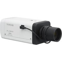
- Inhaltsverzeichnis
- Alarmaufzeichnung
- Alarm Task Editor
- System overview 52
- Operation via the browser 53
- Configuration 58
- Browser connection
- System requirements
- Note:
- Establishing connection
- Password protection in camera
- Password Network
- System overview
- Live page
- 2.2Playback
- Configuration
- Making Changes
- Notice!
- Operation via the browser
- Live page
- Connection
- Video
- Dewarping
- Image selection
- ROI
- Pre-Positions
- Image orientation
- Digital I/O
- Recording status
- Full-screen display
- Saving snapshots
- Recording live video
- Show latest event
- Storage, CPU and network status
- Status icons
- Decoding error
- Alarm flag
- Communication error
- Gap
- Watermark valid
- Watermark invalid
- Motion alarm
- Storage discovery
- 3.2Playback page
- Selecting the recording stream
- Searching for recorded video
- Exporting recorded video
- Track List
- Controlling playback
- Controls
- Configuration
- General
- Identification
- Device name
- Device ID
- User Management
- Authentication modes
- Creating a new user
- Type, select either:
- Date/Time
- Date format
- Device date/Device time
- Device time zone
- Daylight saving time
- Time server address
- Overwrite by DHCP
- Time server type
- Display Stamping
- Camera name stamping
- Logo
- Logo position
- Time stamping
- Display milliseconds
- Alarm mode stamping
- Alarm message
- Transparent background
- Video authentication
- Signature interval [s]
- Web Interface
- Appearance
- Website language
- Company logo
- Device logo
- Show VCA metadata
- Show VCA trajectories
- Show overlay icons
- Show VCA items
- Show ' Dashboard'
- Secure cookie handling
- Latency mode
- Video buffer
- JPEG resolution
- JPEG interval
- JPEG quality
- 'Live' Functions
- Transmit audio
- Lease time [s]
- Show alarm inputs
- Show alarm outputs
- Allow snapshots
- Allow local recording
- I-frames-only stream
- Show 'Pre-positions'
- Path for JPEG and video files
- Video file format
- Camera
- Installer Menu
- Application variant
- Sensor mode
- Image rotation
- Mirror image
- Coding standard
- Camera LED
- Button'MENU'
- Analog output
- Reboot device
- Factory defaults
- Lens Wizard...
- Default
- Zoom
- Focus
- Positioning
- Mounting position
- Tilt angle [°]
- Roll angle [°]
- Height [m]
- Focal length [mm]
- Show sensor values...
- Sketch
- Calibrating cameras using the Sketch Calibration window
- Horizon
- Coordinate system
- Cartesian
- X [m]
- Y [m]
- Z [m]
- WGS 84
- Latitude
- Longitude
- Ground level [m]
- Azimuth [°]
- Scene mode
- Current mode
- Standard
- Sodium lighting
- Fast movement
- Sensitivity boost
- Dynamic backlight
- Vibrant
- Color only
- Sports and gaming
- Retail
- Mode ID
- Copy mode to
- Color
- Brightness (0...255)
- Contrast (0...255)
- Saturation (0...255)
- White balance
- Hold
- RGB-weighted white balance
- R-gain
- G-gain
- B-gain
- ALC
- ALC mode
- ALC level
- ALC - average vs. peak
- Exposure
- Automatic exposure
- Fixed exposure
- Day/Night
- Day-to-night switchover
- Night-to-day switchover
- IR function
- Intensity level
- Enhance
- High dynamic range
- Backlight compensation
- Contrast enhancement
- Intelligent Defog
- Sharpness level
- Intelligent Dynamic Noise Reduction
- Temporal noise filtering
- Spatial noise filtering
- Intelligent streaming
- Dynamic sharpness & noise filtering
- Priority encoder stream
- Scene Mode Scheduler
- Encoder Profile
- Changing a profile
- Profile name
- Bit rate optimization
- Maximum bit rate
- Averaging period
- Target bit rate
- Encoding interval
- Expert Settings
- I-frame distance
- Min. P-frame QP
- I/P-frame delta QP
- Background delta QP
- Object delta QP
- Encoder Streams
- Property
- Non-recording profile
- JPEG stream
- Encoder Statistics
- Line
- Stream
- Encoder Regions
- Privacy Masks
- Exposure priority
- Audio
- Audio
- Audio input
- Microphone volume
- Line Out
- Input volume
- Recording format
- Pixel Counter
- Recording
- Storage Management
- Device manager
- Recording media
- Local Media
- Activating and configuring storage media
- Formatting storage media
- Deactivating storage media
- Recording Profiles
- Stream profile settings
- Settings for selected recordings
- Recording includes
- Standard recording
- Alarm recording
- Alarm stream
- Alarm triggers
- Export to account
- Maximum Retention Time
- Recording Scheduler
- Weekdays
- Holidays
- Time periods
- Activating recording
- Recording Status
- Recording Statistics
- Recording
- SD Card Status
- Lifespan check
- Lifespan alarm
- Alarm
- Alarm Connections
- Connect on alarm
- Number of destination IP address
- Destination IP address
- Destination password
- Video transmission
- Remote port
- Video output
- Decoder
- SSL encryption
- Auto-connect
- Default camera
- Video Content Analysis (VCA)
- Setting up VCA
- Silent VCA
- Profile # 1/ Profile # 2
- Scenario
- Analysis type
- Aggregation time [s]
- Alarm status
- Tamper detection
- Reference check
- Sensitivity
- Trigger delay [s]
- Disappearing edges
- Appearing edges
- Global change
- Global change (slider)
- Current brightness
- Scene too bright
- Scene too dark
- Scheduled
- Event triggered
- Trigger
- Trigger active
- Trigger inactive
- Delay [s]
- Audio Alarm
- Audio alarm
- Name
- Signal Ranges
- Threshold
- Alarm E-Mail
- Send alarm e-mail
- Mail server IP address
- SMTP port
- SMTP user name
- SMTP password
- Format
- Image size
- Attach JPEG from camera
- VCA overlays
- Destination address
- Sender address
- Test e-mail
- Interfaces
- Alarm Inputs
- Active
- Action
- - None
- - Monochrome
- - Switch mode
- Alarm Outputs
- Idle state
- Operating mode
- Output follows
- Output name
- Toggle
- Network
- Network Services
- Network Access
- Automatic IPv4 assignment
- Ethernet
- IP V4 address
- IP address
- Subnet mask
- Gateway address
- IP V6 address
- Prefix length
- DNS server address 1/DNS server address 2
- UDP encryption
- TCP rate control
- HTTP browser port
- HTTPS browser port
- Min. TLS version
- Allow basic auth on non-SSL
- HSTS
- RCP+ port 1756
- Discovery port (0 = Off)
- Interface mode ETH
- Network MSS [Byte]
- Network MTU [Byte]
- Advanced
- RTSP port
- Authentication (802.1x)
- TCP metadata input
- Syslog
- Server IP address
- Server port (0 = Off)
- Protocol
- LLDP power config
- Requested for camera
- Additional Power
- Requested total
- Additional Power.
- Allocated power
- Network Management
- SNMP
- SNMP host addresses
- SNMP traps
- UPnP
- Quality of service
- Multicast
- Enable
- Multicast Address
- Port
- Streaming
- Multicast packet TTL
- IGMP version
- Image Posting
- JPEG
- File name
- Posting interval
- Post JPEG from camera
- Target
- Accounts
- Type
- Account name
- FTP server IP address
- FTP server login
- FTP server password
- Path on FTP server
- IPv4 Filter
- Service
- Maintenance
- Upload history
- Configuration
- Maintenance log
- Licences
- Certificates
- File list
- Add a certificate/file to the file list
- Delete a certificate from the file list
- Download a certificate
- Logging
- Event Logging
- Current log level
- Number of displayed entries
- Software Sealing
- Enable software sealing
- Debug Logging
- Diagnostics
- Reload
- Download log
- System Overview
- Appendices
- Copyright notices
- Contenido
- Table des matieres
- Authentication video
- Luminosite (0...255)
- Ynpabneneuepe36pay3ep 234
- Konfumypauzaia
- PpnoJKeHn
- 1Подклю悔нe6payзерa
- Tpe6obHnK cnTeMe
- PnmuMeuHne.
- YcTaHOBLeHne NpOdkNIOUeHnA
- PnmeaHne.
- 3auneta kamepbipnapoem
- Cetb naponei
- 063op cnCTeMbI
- Konfugrupaun
- BheceHne 3MeHeHH
- 3ameuahne!
- YnpaBHeHne uepe3 6pay3ep
- CtrpaHnca «PpocMOTp B peXmpeaIbHOro BpeMeHH»
- PoiKJIIOUeHHe
- Budoe
- YcTaPaHeHne NCKaKeHH
- Bb6op n3o6paXeHH
- OpneHTaunn H3o6paKeHn
- 3aHcB HHTepaKTbHOrO BnDeo
- Poka3aTb nocneJHHee co6bItne
- CocToaHHe cHCTeMbI xpaHenHa, Ln H cetn
- 3HaCKn COCTOHHN
- OuH6ka deKoOpOBaHHa
- Φnar TpeBorN
- Oun6ka CBA3N
- Pponyck
- DeiCTBNTeJIbHbI BODHOH 3HaK
- HeJeCTBHTeIbHbI BOaHOH 3HaK
- TpeBxHbI cHrHan DnBxKeHHa
- 06HapyKeHHe xpaHHnHa
- CtrpaHnca «BocnpOn3VeJeHne»
- Bb6op notoka 3annch
- 3.2.2ПоннкЗанcaHHoroBndeo
- 3KcnpT 3aHcaHHoro Bndeo
- Pnmeuahne.
- Cnncokdopojke
- YnpaBHeHne Bocnpon3BeDeHHem
- 3nemEnbnypaBneHn
- Konfugpaun
- 067ne
- HdeHTnФнkaця
- YnpaBneHne noIb3oBaTeJMaH
- Co3dHHe HOBOro nOJIb3OBaTeNa
- BbIOd Ha3BaHHaMepebl
- Norotn
- NooxeHne norotnna
- BbIOBd BpeMeHH
- OTo6paKaTaB MmIHHceKyHdbI
- BbIOd peKmA trpeBorH
- Tpeboxhoe coo6eHne
- PpO3paHbIΦH
- PpOBepKa noDnHHNcTH BnDeo
- HHTepBaI noOpnnc (c)
- Be6-нтерфейс
- Bn
- A3bIK Be6-CTpaHnucbl
- IorotnKOMnHaHH
- Iorotn yctpoNCTBa
- Poka3aTb MeTaDaHHbIe VCA
- Poka3aTb TpaekTopn VCA
- Pokaatb nepekepbibaounece 3haKu
- PeknIm 3aepKKn
- Pa3Mep JPEG
- HHTepBan JPEG
- KaueCTBO JPEG
- 4.2.2Функи npocmOTpaВpekme peaIbHoro BpeMeHH
- Ipeepaaydno
- BpemaapeHdbi (c)
- Pa3peWHTb cHmKn
- Pa3peWntb IOKaIbHyIO 3anncb
- Iotok tonbko I-kaapob
- Poka3atb "Ppeno3nncn"
- IybKJPEG- HnBndeofoaainam
- ΦopMaT BnDeoFaIa
- Kamepa
- MeHIO yCTaHOBKn
- Bapnnt npmmehen
- PexmmMatpncbl
- CBeToIIOKaMepbI
- Ipeesarpy3ntb yctpoiCTBO
- 3aBODcKne npaMeTpbl no ymonuahnlo
- POnHIOHOHPoBaHne
- Pexm cHebl
- Tekyusipexmm
- Apkn
- Cnopt n urpa
- ToprobbieyupexkdeHn
- IeHTnΦkaTOp pexma
- KoHpoBaTbpeXIMB
- BocctahOBHTb cTaNapThbIe npaMeTpbl peKIma
- Lbetnoj pexnm
- RpkocTB (0-255)
- YpOBeHyETKoCTN
- ΦnltbP BpemHoro Wyma
- ΦHbTp npoctpaHCTBeHHoro Wyma
- Donyctmao own6ka napametpa nckpetn3aun nn fooha
- Donyctmao own6ka npametpa dnckpeTHaunn noBeKToB
- Noymouanhku
- ItoKoepa
- CBOIcTBO
- PpOΦnB 6e3aHnc
- CtaTnCTnKa 3aHnCn
- 3aHc6
- MacstTa6HpoBaHne
- PepnoD ycpedHn
- CoctoHne SD-KapTbI
- Tpebora
- Npoknquen TpeBorN
- PoiKluoyenne no TpeBore
- IP-adpec Homepa nyHKta Ha3haeHHa
- IP-adpec nyHKta Ha3haueHn
- Paponb nyHKta Ha3HaueHn
- PepedaBndeocnHana
- Pnmeuahne
- Notok
- ydaenHHn nopT
- BndeobbIXoJ
- PnmuueaHne
- Декорер
- UHΦpOBAHne SSL
- AbTomatueckoe noKnioueHne
- Aydno
- Kamepa no ymoJuaHHIO
- AhaHn3 BndeoHaHbIx (VCA)
- PpmeaHne
- Hactpoika VCA
- VCA B6ecwymHom pexnme
- PpOΦunb # 1/ PpOΦunb # 2
- BpeMaobbeaHHeHHa (c)
- TnnaHann3a
- Cuehapn
- Ipekepcthn npoBepka
- UyBCTbHTenbHOCTb
- 3aepkka cpa6aTbHaHn (c)
- Hcye3aioune kpa
- PnBnIOUncKpa
- Tno6anbHoe n3MeHeHne
- Tno6anbHoe n3MeHeHne (perynrTop)
- CnHsKOM BbICOKaApKocTb
- CnHsKOM cna6oe ocBeueHne
- No paacnncannu
- Hnunpyetc co6bIthem
- Tpurrrep
- TprrrepakTHBEN
- Tprrrep HeaKTHBEN
- 3aepkka (c)
- Aynotpebora
- AydnoptpeBora
- HMA
- Hana3oH CnHana
- Nopor
- UyBCTBHTeJIbHOcTb
- ΘneKtpoHnOe coo6uEHHe TpeBorH
- Otnpabntb coo6eHne o tpeBore no 3neKtponHnoTte
- IP-adpec nouToboro cepBepa
- IopT SMTP
- Hm nonb3oBatea SMTP
- Napolb SMTP
- Φopmat
- Pa3Mep n3o6paxeHnA
- Bnoxntb JPEG c kamepbI
- CeTb
- YcTaHOBHTb MeHReTcHa Yc. n nepe3arp..
- CeTeBbIe cnyx6bl
- Doctyn K cetn
- ABTom. Na3NaueHne IPv4-apeca
- Adec Ipv4
- IP-aDpec
- Macka noDCetn
- Ampc uio3a
- AdecIPv6
- DnHa npefnkca
- Adec wio3a
- Aapec DNS-cepBepa 1/Aapec DNS-cepBepa 2
- Nepeda BndeocnHa
- KoHTpObnckOpocnnepeaHT TCP-naKeTob
- Nopr HTTP-6pay3epa
- Iopr HTTPS-6pay3epa
- Bepcn Min.TLS
- RCP+ nopT 1756
- Pekim nHTepceica ETH
- MaKc. pa3Mep cerMeHTa BCeTn (6aHT)
- MTU cetn (6aHT)
- DononHntelbHO
- Nopt RTSP
- PpOBepKa noDHHHocTn (802.1x)
- Bbod metadaHbix TCP
- IP-apec cepbepa
- NopT cepBepa (0 = B_bikn)
- KoHpypaunnntaun LLDP
- 3anpoweNo nla kamepbbl
- DOnonHHTenbHaM MoaHocTb
- 3anpoeweBcero
- DononHntenbHa MoUHOCTb,
- BbIeHnHa MoUHocTb
- YnpaBneHne cetbIO
- Adeca y3no8SNMP
- KaueCTBO 06cnyKBAHNA
- TTL naketa npn Mhoroaep. nep.
- Ny6nkaun CHNMKOB
- Tekyuni ypOBeHb BeDenHn KypHa
- KoHueCTBO OTo6paKaMaBix 3aHncEi
- Bknouhtb 3aunty nporpamMhoro oecneueHn
- DnarHocTnKa
- Ppe3arpy3ntb
- 3arpy3ntb kyphan
- O63op cncTeMbI
- 5Пиложеня
- YbeDomJIeHnO6 aBTOpCKnx npaBax
Brand : SONY
Model : SNCHMX70
Category : Surveillance Camera