
TVAC26000 - Video surveillance remote ABUS - Free user manual and instructions
Find the device manual for free TVAC26000 ABUS in PDF.

| Product type | Control keyboard for PTZ cameras and DVRs |
| Brand | ABUS |
| Model | TVAC26000 |
| Dimensions (L x W x H) | 360 x 200 x 108 mm |
| Weight | 3.3 kg |
| Power supply | 12 V DC (via power adapter 100-240 V AC) |
| Supported protocol | Pelco D/P |
| Communication interface | RS-485 |
| Maximum number of controllable PTZ | 255 |
| Maximum number of controllable DVRs | 31 |
| Joystick type | 3D (up, down, left, right, zoom in/out) |
| Maximum RS-485 cable length | 1,200 m |
| Operating temperature | -10 °C to 55 °C |
| Display | LCD screen with backlight, power saving after 30 s |
| Main functions | PTZ control (pan, tilt, zoom), presets, tours, DVR control (playback, recording, search), OSD menu |
| Package contents | Control keyboard, 12 V DC power adapter, 2 x 5-pin terminal blocks, instruction manual |
| Care and cleaning | Clean with a dry or slightly damp cloth (warm water). Do not use chemicals. Do not open the housing. |
| Safety | Unplug before cleaning. Do not expose to moisture, extreme heat or direct sunlight. Use only the supplied power supply. |
| Repairability and spare parts | No user-serviceable parts. Contact a professional installer in case of failure. |
| Recycling | Do not dispose of with household waste. Comply with local regulations. |
| General information | Manufactured by ABUS Security-Center GmbH & Co. KG, Germany. Keep instructions for future use. |
Frequently Asked Questions - TVAC26000 ABUS
User questions about TVAC26000 ABUS
0 question about this device. Answer the ones you know or ask your own.
Ask a new question about this device
Download the instructions for your Video surveillance remote in PDF format for free! Find your manual TVAC26000 - ABUS and take your electronic device back in hand. On this page are published all the documents necessary for the use of your device. TVAC26000 by ABUS.
USER MANUAL TVAC26000 ABUS
These user manual contains important information for installation and operation. This should be also noted when this product is passed on to a third party. Therefore look after these operating instructions for future reference!
A list of contents with the corresponding page number can be found in the index on page 18.
Français
password setup
CAM: 001 DEFAULT SETUP
PROTOCOL SOUND SETUP
BAUD RATE KEYBOARD ID SETUP
Thank you for purchasing this product.
This product meets the requirements of the applicable European and national guidelines. The corresponding declarations and documents can be obtained from the manufacturer (www.abus-sc.com).
To maintain this condition and to ensure risk-free operation, you as the user must observe these operation instructions!
Before initial start-up, read through the complete operating instructions observing operating and safety instructions.
All company and product names mentioned in this document are registered trademarks. All rights reserved.
If you have any questions, please contact your installer or your local dealer!

Disclaimer
This user manual was prepared with greatest care. If you should notice omissions or inaccuracies, please inform us about these on the back of this manual given address. The ABUS Security-Center GmbH assumes no liability for technical and typographical faults and reserves the right to make at any time modifications to the product or user manual without a previous announcement. The company is not liable or responsible for direct and indirect subsequent damages which are caused in connection with the equipment, the performance and the use of this product. No guarantee for the content of this document is taken.
Icon explanation
| A flash in the triangle is used if there is danger for the health, e.g. by an electric shock. | |
| An excclamation mark in the triangle points to an important note in this user manual which must be minded. | |
| This symbol can be found when you are to be given tips and information on operation. |
Important safety advice
| The warranty will expire for damage due to non-compliance with these operating instructions. ABUS will not be liable for any consequential loss! | |
| ABUS will not accept liability for damage to property or personal injury caused by incorrect handling or non-compliance with the safety-instructions. In such cases the warranty will expire. |
The device has been manufactured in compliance with international safety standards. Please read these safety advices carefully.
Safety advice
- Mains supply
100-240 V AC, 50-60 Hz (via power adapter plug to 12 V DC)
Operate this product only from the type of power supply indicated on the marking label. If you are not sure of the type of power supplied to your home, consult your local power company. Disconnect the product from the mains before you start any maintenance or installation procedures.
- Overloading
Do not overload a wall outlet, extension cord or adapter as this may result in electric fire or shock.
- Liquids
Protect the device from any kind of liquids entering.
- Cleaning
Disconnect the product from the wall outlet before cleaning. Use a light damp cloth (no solvents) to dust the product.
- Accessories
Do not use any unsupported accessories as these may be hazardous or cause damage the product.
Warnings
Follow all safety and operating advises before starting-up the device!
-
Observe the following information to avoid damage to the mains cable and plug:
-
Do not modify or manipulate the mains cable or plug.
- Do not pull the cable when disconnecting the device from the mains power - always take hold of the plug.
-
Ensure that the mains cable is positioned as far away as possible from any heating equipment, as this could otherwise melt the plastic coating.
-
Follow these directions. Failure to follow any of them may cause electrical shock:
-
Do not open the main body or the power supply.
- Do not insert metal or inflammable objects inside the product.
-
In order to avoid any damage during lighting use a surge protection.
-
Do not use the product when it is out of order. If you continue to use the product when defective, serious damage can be caused to it. Make sure to contact your local product distributor if the product is out of order.
|  | During the installation into an existing video surveillance system make sure that all devices are disconnected from the low and supply voltage circuit. |
|  | If in doubt allow a professional electrician to mount, install and wire-up your device. Improper electrical connection to the mains does not only represent at threat to you but also to other persons. Wire-up the entire system making sure that the mains and low voltage circuit remain separated and cannot come into contact with each other in normal use or due to any malfunctioning. |
Avoid using the device under the following unfavorable ambient conditions:
- wetness or excessive air humidity
- extreme cold or heat
- direct sunlight
- dust or combustible gases, vapors or solvents
- strong vibration
- strong magnetic fields, such as those found in the vicinity of machinery or loudspeakers
Unpacking
While you are unpacking the device please handle it with utmost care.
| i | If you notice any damage of the original packaging, please check at first the device. If the device shows damages, please contact your local dealer. |
English
Table of contents
- Intended Use 19
- Scope of delivery 19
- Features and functions 19
- Description of device 19
4.1 Rear view of control panel 19
4.2 Front view of control panel 20
4.3 Joystick control 21
4.4 LCD display 21
- Control panel configuration 21
5.1 Control panel menu 21
5.2 Changing the protocol and baud rate 22
- Typical circuit diagram 23
6.1 Speed Dome control 23
6.2 DVR control 23
- Maintenance and cleaning 24
7.1 Maintenance 24
7.2 Cleaning 24
- Disposal 24
- Technical data 24
1. Intended Use
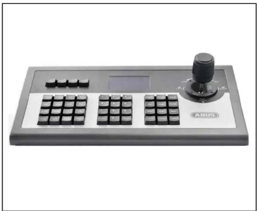
The TVAC26000 control panel is used for centrally controlling PTZ cameras and DVRs with the RS-485 interface.
The following DVRs are compatible: TVVR4xxxx, TVVR50xxx and TVVR60xxx.
2. Scope of delivery
| No. | Items | Quantity |
| 1 | Control panel | 1 |
| 2 | 12 V DC power supply unit | 1 |
| 3 | 5-pin terminal connector strip | 2 |
| 4 | User manual | 1 |
3. Features and functions
- PTZ Speed Dome control
DVR control
Control panel can operate up to 31 DVRs
Control panel can operate up to 255 PTZ devices
4. Description of device
4.1 Rear view of control panel
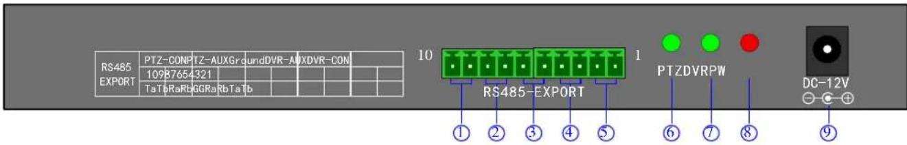
| No. | Connection | Explanation |
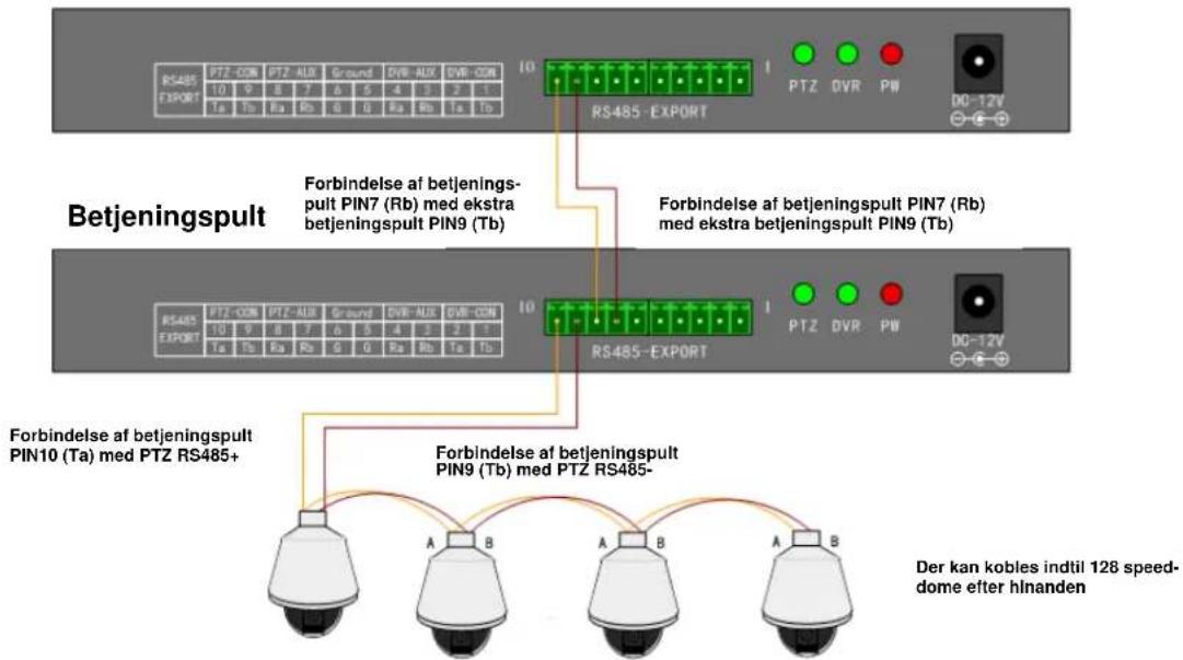
| 1 | Output for PTZ control PTZ-CON | RS485 connection for linking control panel and PTZ Speed Dome. Ta is for RS485+ and Tb is for RS485-. |
| 2 | Input for additional control panel for PTZ control PTZ-AUX | Connect the control panel and additional control panel for PTZ control. Connect control panel PIN8 (Ra) with additional control panel PIN10 (Ta), and connect control panel PIN7 (Rb) with additional control panel PIN9 (Tb). The additional control panel can now also control the PTZ Speed Dome. |
| 3 | Earth | Earth connection |
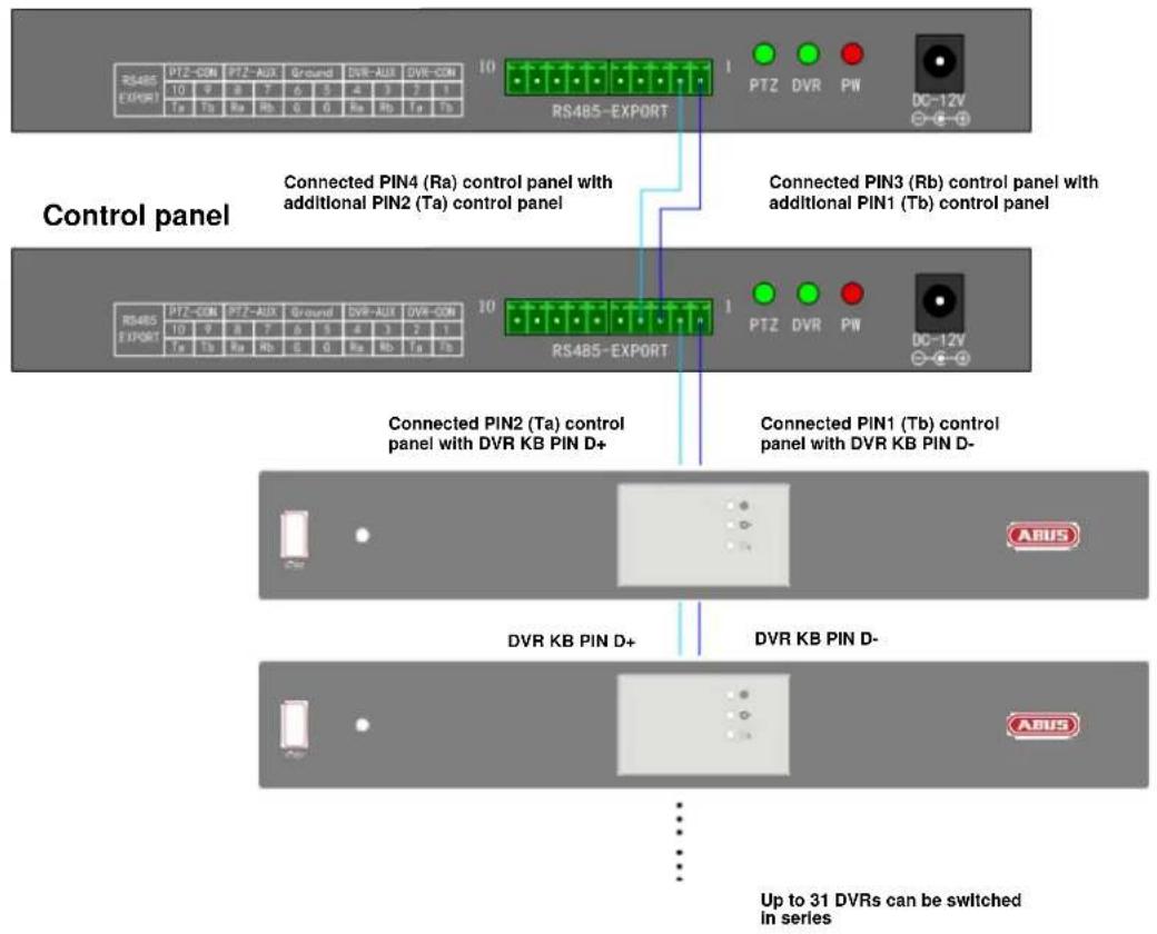
| 4 | Input for additional control panel for DVR control DVR-AUX | Connect the control panel and additional control panel for DVR control. Connect control panel PIN4 (Ra) with additional control panel PIN2 (Ta), and connect control panel PIN3 (Rb) with additional control panel PIN1 (Tb). The additional control panel can now control a DVR. |
| 5 | Output for DVR control DVR-CON | Connect control panel PIN2 (Ta) with DVR KB PIN D+, and connect control panel PIN1 (Tb) with DVR KB PIN D-. |
| 6 | PTZ indicator lamp | In the PTZ operating mode, the green LED lights up and flashes. |
| 7 | DVR indicator lamp | In the DVR operating mode, the green LED lights up and flashes. |
| 8 | Power LED PW | The Power LED lights up red once the power supply is connected. |
| 9 | DC-12 V voltage supply | Power supply connection |
4.2 Front view of control panel
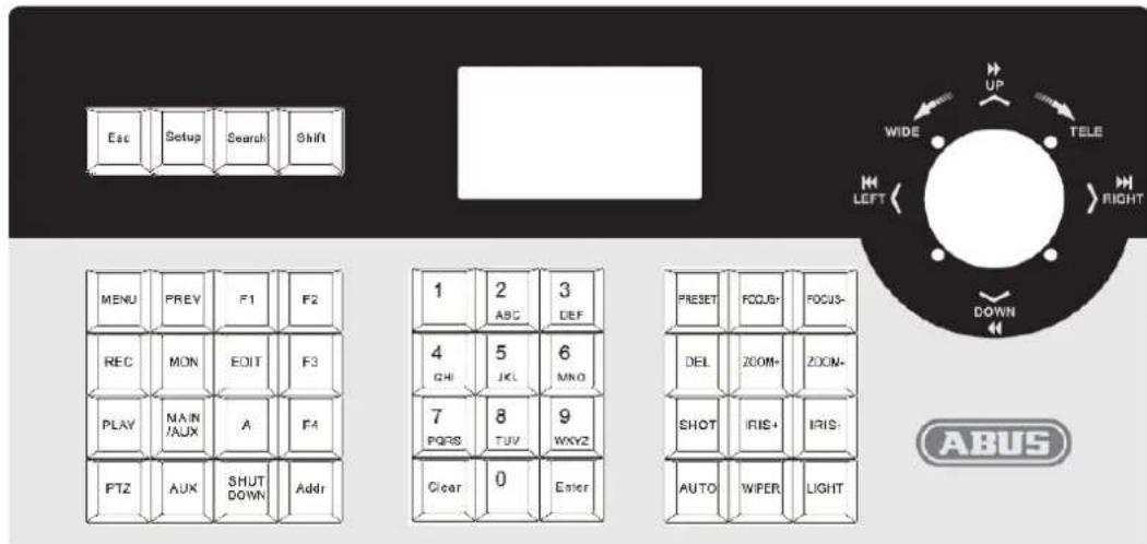
| Button | Explanation |
| ESC | Back to previous menu |
| Setup | Hold down for three seconds to go to the configuration menu (using standard password: 8888, master password: 1111) |
| Search | Press for one second to see the PTZ configuration |
| Shift | Change between DVR and PTZ operating modes |
| MENU | Opens the main menu |
| PREV | Select between the 1st, 4th, 9th, 12th and 16th previews for your DVR |
| F1 | Reserve |
| F2 | Reserve |
| REC | You go to the menu of the recorder connected |
| MON | Reserve |
| EDIT | Make changes in the recorder menu |
| F3 | Programme a tour |
| PLAY | Opens playback in the recorder |
| MAIN/AUX | Select output between two connected monitors (press for 2 seconds) |
| A | Select between upper and lower case letters, or numbers |
| F4 | Start a tour |
| PTZ | Opens the PTZ menu |
| AUX | Reserve |
| Shut Down | Shut down the recorder |
| Addr | Change the ID for PTZ Speed Dome or DVR |
| Clear | Delete current entries |
| ENTER | Confirm current entries |
| 0-9 | Numbers: 0, 1, 2, 3, 4, 5, 6, 7, 8, 9 |
| A-Z | A-Z (26 characters) |
| PRESENT | Save preset positions |
| FOCUS+ | Near focus |
| FOCUS- | Far focus |
| DEL | Delete preset position |
| ZOOM+ | Increase zoom factor |
| ZOOM- | Reduce zoom factor |
| SHOT | Open saved preset position |
| IRIS+ | Open IRIS |
| IRIS- | Close IRIS |
| Auto | Performs an auto scan |
| WIPER | Reserve |
| Light | Reserve |
4.3 Joystick control
| Picture | Command | Explanation |
| Up | In PTZ operating mode: move camera upwards | |
| In DVR operating mode: watch fast playback | ||
| Down | In PTZ operating mode: move camera downwards | |
| In DVR operating mode: watch slow playback | ||
| Left | In PTZ operating mode: move camera to the left | |
| In DVR operating mode: start reverse playback | ||
| Right | In PTZ operating mode: move camera to the right | |
| In DVR operating mode: start forward playback | ||
| Rotates left | Increase zoom factor | |
| Rotate right | Reduce zoom factor |
4.4 LCD display
Each operation is detected and displayed by the LCD display. The LCD display goes into energy-saving mode (minimises the illumination) if there is no operation for 30 seconds.
| i | Pressing the F4 key does not start a tour with the PTZ TV7600-05 cameras. Start tour 1~8 by pressing the 71~78 + Preset key combination. The menu key does not open the OSD menu with the PTZ TV7600-05 cameras. Open the OSD menu by pressing the 95 + Preset key combination. |
5. Control panel configuration
5.1 Control panel menu
Any control panel configurations and queries can be done using the joystick and some essential keys.
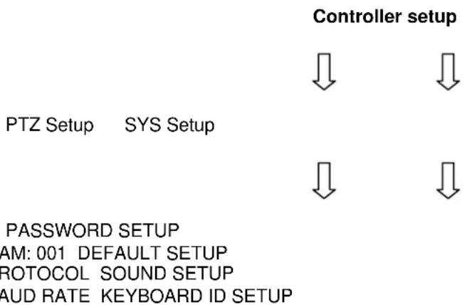
5.2 Changing the protocol and baud rate
The example below describes how you can change the protocol in Pelco-D and the baud rate to 4800 for Speeddome 002:
- From the standby mode (Fig. 1), press and hold down the "Setup" button for three seconds (Fig. 2).
- Enter the password (Fig. 3, standard password: 8888).
- Press "Enter" to go to the Setup menu. Navigate with the joystick to PTZ SETUP (Fig. 4).
- Press "Enter" to go to the PTZ menu.
- Move the joystick to the left or right to select the Speed Dome address (Fig. 5). Then press "Enter" to confirm the changes (Fig. 6).
- Move the joystick up and down to select the protocol (Fig. 7).
- Move the joystick to the right to change the baud rate (Fig. 8). Then move the joystick to select the baud rate (Fig.9).
- Press "Enter" followed by "ESC" until you are in standby mode. (Fig. 1).
- The configuration is now complete.

Fig.1 Fig.2 Fig.3


Fig. 4

Fig. 5

Fig. 6

Fig. 7

Fig. 8

Fig. 9
6. Typical circuit diagram
6.1 Speed Dome control
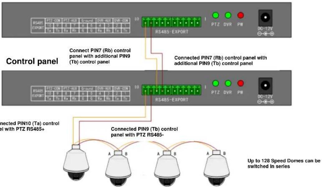
Additional control panel
6.2 DVR control
Additional control panel
7. Maintenance and cleaning
7.1 Maintenance
Regularly check the product's physical state, e.g. check for damage of the housing.
If you suspect that safe operation cannot be guaranteed anymore, disconnect the product and ensure that it cannot be used by mistake.
You can assume that safe operation is not possible anymore when
- the device shows visible damage,
- the device does not function anymore

Please note:
The product is maintenance free for you. Inside the product are no parts that can be checked or repaired, so do not ever open it.
7.2 Cleaning
Wipe the product with a clean, dry cloth. If the device is very dirty, you can moisten the cloth with lukewarm water.

Make sure that no liquids can enter the equipment as the device can be destroyed. Never use chemical detergents as they could attack the surface of the device
8. Disposal
Devices with this marking should not be put in the household garbage. Dispos of the product at the end of its lifetime according to the applicable regulations.
9. Technical data
| Model number TVAC26000 | |
| Number of DVRs supported | 31 |
| Number of PTZs supported | 255 |
| Protocol | Pelco D/P |
| Connection | RS-485 |
| Joystick | 3D |
| Maximum cable length | 1200 m |
| Power supply | 12V DC |
| Operating temperature | -10 °C – 55 °C |
| Dimensions (L x W x H) | 360 x 200 x 108 |
| Weight | 3.3 kg |
TVAC26000
Manuel utiliseur
Version 11/2011
Introduction
Chere cliente, cher client,
CAM:001 DEFAULT SETUP
PROTOCOL SOUND SETUP
BAUD RATE KEYBOARD ID SETUP
CAM:001 DEFAULT SETUP
PROTOCOL SOUND SETUP
BAUD RATE KEYBOARD ID SETUP
CAM:001 DEFAULT SETUP
PROTOCOL SOUND SETUP
BAUD RATE KEYBOARD ID SETUP
6.1 Styring at speed-dome
Ekstra betjeningspult
6.2 Styring af DVR
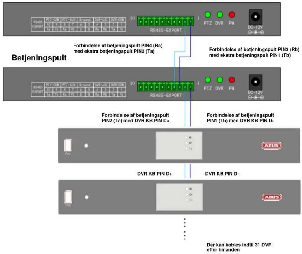
Ekstra betjeningspult
These operating instructions are published by ABUS Security-Center GmbH & Co.KG, Linker Kreuthweg 5, 86444 Affing, Germany. No reproduction (including translation) is permitted in whole or part e.g. photocopy, microfilming or storage in electronic data processing equipment, without the express written consent of the publisher.
The operating instructions reflect the current technical specifications at the time of print.
We reserve the right to change the technical or physical specifications.
F Note de l'éditeur
- Disclaimer
- Icon explanation
- Important safety advice
- Safety advice
- Warnings
- Unpacking
- English
- Table of contents
- Intended Use
- Scope of delivery
- Features and functions
- Description of device
- Rear view of control panel
- Front view of control panel
- Joystick control
- LCD display
- Control panel configuration
- Control panel menu
- Changing the protocol and baud rate
- Typical circuit diagram
- Speed Dome control
- DVR control
- Maintenance and cleaning
- Maintenance
- Please note:
- Cleaning
- Disposal
- Technical data
- TVAC26000
- Manuel utiliseur
- Introduction
- Styring at speed-dome
- Styring af DVR
- F Note de l'éditeur
Brand : ABUS
Model : TVAC26000
Category : Video surveillance remote