
MIA 2 11 - Pan OLIMPIA SPLENDID - Free user manual and instructions
Find the device manual for free MIA 2 11 OLIMPIA SPLENDID in PDF.

| Product type | Pellet stove |
| Brand | Olimpia Splendid |
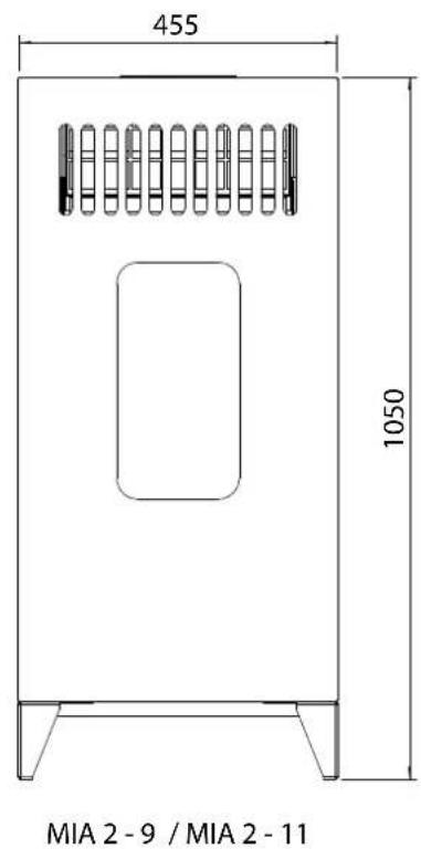
| Model | MIA 2 11 |
| Nominal thermal power | 8.88 kW |
| Reduced thermal power | 2.0 kW |
| Nominal efficiency | 88.78 % |
| Reduced efficiency | 95.48 % |
| Nominal flue gas temperature | 154.2 °C |
| Reduced flue gas temperature | 52.3 °C |
| Draft | 10-12 Pa |
| Power supply | 230 V / 50 Hz |
| Power consumption (ignition) | 280 W |
| Power consumption (operation) | 100 W |
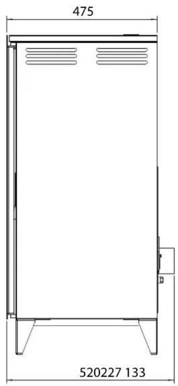
| Weight | 83 kg |
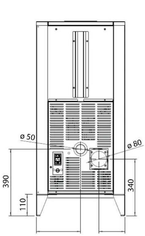
| Flue gas outlet diameter | 80 mm |
| Fuel type | Wood pellets, diameter 6 mm, max length 30 mm |
| Side and rear safety distances | 40 cm |
| Front safety distance | 80 cm |
| Power levels | 5 (1 to 5) |
| Special functions | Turbo, Sleep, Auto, Eco (via remote control) |
| Display | 7 segments with indicator lights |
| Burner cleaning | Daily |
| Annual maintenance | Required by Authorized Service Center |
| Glass type | Ceramic 4 mm, self-cleaning |
Frequently Asked Questions - MIA 2 11 OLIMPIA SPLENDID
User questions about MIA 2 11 OLIMPIA SPLENDID
0 question about this device. Answer the ones you know or ask your own.
Ask a new question about this device
Download the instructions for your Pan in PDF format for free! Find your manual MIA 2 11 - OLIMPIA SPLENDID and take your electronic device back in hand. On this page are published all the documents necessary for the use of your device. MIA 2 11 by OLIMPIA SPLENDID.
USER MANUAL MIA 2 11 OLIMPIA SPLENDID
natural_image
Exterior view of a modern white portable stove with vented glass and side legs (no text or symbols visible)INSTRUCTIONS FOR INSTALLATION, USE AND MAINTENANCE

INSTRUCTIONS POUR L'INSTALLATION, L'EMPLOI ET L'ENTRETIEN

natural_image
Close-up of a hand holding a small metallic object inside a transparent container (no visible text or symbols)Fig. 1 Fig. 2
natural_image
Hand using a tool to remove or remove a dark object inside a stainless steel appliance (no visible text or symbols)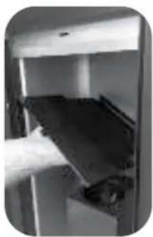
natural_image
Close-up of a hand holding a dark object inside a metallic enclosure (no visible text or symbols)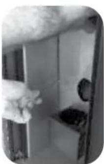
natural_image
Close-up of a hand opening a door with a black handle, no visible text or symbolsFig. 3 Fig. 4
natural_image
Close-up of hands using a tool to adjust or install electronic components (no visible text or symbols)Fig. 5 Fig. 6
natural_image
Close-up of a hand holding a white mechanical component with metal brackets (no visible text or symbols)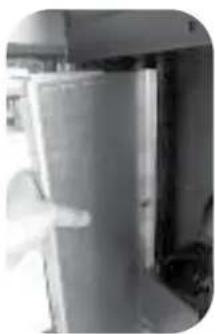
natural_image
Interior view of a kitchen or storage room with a door and window (no visible text or symbols)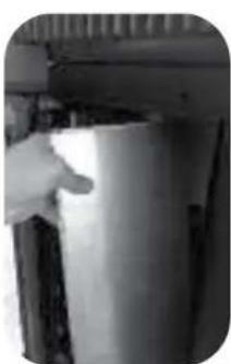
natural_image
Close-up of a hand holding a small object near a vertical structure (no visible text or symbols)Fig. 7 Fig. 8
natural_image
Close-up of a metallic mechanical component with a circular opening and a cylindrical protrusion (no visible text or symbols)Fig. 9 Fig. 10
natural_image
Close-up of a hand holding a small object near a metallic device (no visible text or symbols)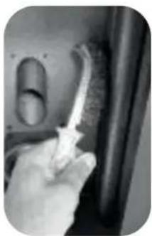
natural_image
Close-up of a hand holding a brush near a wall, no visible text or symbolsFig. 11 Fig. 12
natural_image
Close-up of a hand holding a medical or laboratory instrument near a metallic component (no visible text or symbols)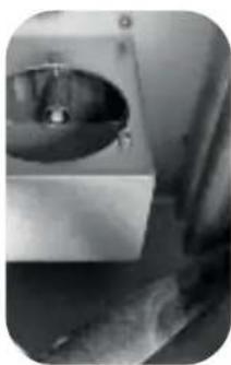
natural_image
Close-up of a metallic mechanical component with a circular opening and a small handle, possibly a valve or pump (no visible text or symbols)Fig. 13 Fig. 14
natural_image
Close-up of electrical wires and components (no visible text or symbols)
natural_image
Close-up of a mechanical component with a pointed tool inserted into a circular opening (no visible text or symbols)Fig. 15
natural_image
Close-up of a hand interacting with a large pipe fitting inside a control panel (no visible text or symbols)Fig.23 Fig.24
natural_image
Hand holding a small cylindrical object on a shelf, with a ruler and stacked boxes in the background (no visible text or symbols)natural_image
Close-up of a hand using a tool to stir contents in a container (no visible text or symbols)Fig.25a Fig.25b
natural_image
Hand holding a small object with a pointed tip, placed on a wooden surface (no visible text or symbols)7.7 Cassetto cenere
natural_image
Two black-and-white photos showing a laboratory apparatus with a central circular component and a hand interacting with it (no visible text or symbols)Fig. 26
Carefully read the precautions and follow the procedures correctly.

WARNING!

In case of breakage or poor functioning always contact the Authorized Assistance Centre; any attempt to remove parts or perform maintenance on the device can expose the user to electrical shock danger.
The stove contains parts whose maintenance must be done by the Authorized Assistance Centre.
The stove is a heating device; its parts reach extreme temperatures and contact without adequate protection can provoke burns of various degrees.
Pay particular attention to children.
In case of a transfer, contact the Authorized Assistance Centre for the removal and new installation.
Do not insert fingers or other objects in the air flow exit slits.
Inside the device there is a high speed fan that could cause grave personal injury. Pay particular attention to children.
Do not remain for long periods directly exposed to the flow of hot air. Direct and prolonged exposition to the cold air could be hazardous to health.
Pay particular attention in rooms where there are children, the elderly or the ill. In case the stove functions poorly, shut down the device immediately and contact the Authorized Assistance Centre.
The continued use of the device in said conditions can cause fires or flashes. Failure to carry out maintenance or maintenance not carried out as stated in this manual may cause danger and harm to persons or property.
WARNING!
During the stove installation operation, keep children out of the work area to avoid unforeseen accidents.
Do not block or cover in any way the body of the stove or obstruct the slits placed on the upperside.
Obstructing said slits can cause fires.
Do not use the stove in areas containing precision devices or works of art.
The quality of the conserved objects may deteriorate.
Do not expose animals or plants to direct air flow from the unit.
Prolonged direct exposition to the flow of air from the stove can have negative effects on plants and animals.
Occasionally ventilate the room during the use of the device.
Insufficient ventilation can be the origin of insufficient oxygen in the room.
Do not expose the stove to contact with water.
The electrical insulation could be damaged, with the consequent possibilities of electrocution and breakage due to the thermal extremes.
Verify the installation conditions to locate eventual damage.
After the stove has completed 1000-1200 hours of operation (the lower screen will read "SErV"), contact the Authorized Assistance Centre for cleaning and ordinary maintenance.
Do not use inflammable gas near the stove.
Unhook the automatic switch if the device will not be used for long periods of time.
We check the start up of all our stoves.
Norms and conformity declarations
Legislation
- Our company declares that the stove conforms to the following norms for EC European Directive marking.
• 2014/30/EU, ElectroMagnetic Compatibility Directive (EMCD)
• 2014/35/EU, Low Voltage Directive (LVD) - 2011/65/EU, Restriction of the use of certain hazardous substances Directive (RoHS Directive)
• Regulation of the CPR (EU 305/2011). - For installation in Italy refer to the UNI 10683/98 or successive modifications; the technician installing the hydrothermal sanitary system will issue the declaration of conformity according to L. 37/2008. The installation of appliance has to be in accordance with local and national laws and with European norms.
- EN 55014-1; EN 55014-2; EN 61000-3-2; EN 61000-3-3; EN 60335-1; EN 60335-2-102; EN 62233; EN 50581; EN14785.

Generic danger
- Signals to personnel that if the operation described is not performed strictly according to the safety regulations, it could cause the risk of personal injury.
Responsibility
The manufacturer declines every direct or indirect, civil or penal responsibility due to:
- Poor maintenance.
- Failure to observe the instructions contained in the manuals.
- Use in non-conformity with the safety directives.
- Installation in non-conformity with the norms in force in the country.
• Installation by unqualified or untrained personnel. - Modifications and repairs not authorized by the manufacturer.
- Use of non-original replacement parts.
- Exceptional events.
- Use of pellets not approved by the manufacturer.
Installation
Flue
The flue must meet the following requirements:
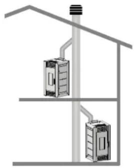
- No other type of chimney, stove, boiler or hood vent must be connected (fig.1).
- It must be adequately distanced from combustible or inflammable material by means of an air cavity or opportune insulation.
- The internal section must be uniform, preferably circular: the square or rectangular sections must have rounded corners with a radius of no less than 20 mm, a maximum relationship between the sides of 1.5; the walls as smooth as possible with no narrowed sections, regular curves and no discontinuities, with deviations from the axis not more than 45°.
- Every device must have its own flue with a diameter equal to or larger than the stove's smoke clearing tube and a height not less than that declared.
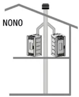
- Never use two stoves, a chimney and a stove, a stove and a wood kitchen, etc in the same environment, since the draught of one could damage the draught of the other.
- Collective type ventilation ducts that can lower the atmospheric pressure in the in-
stallation environment are not permitted, even if installed in environments that are adjacent to and communicating with the locale of the installation.
- It is forbidden to make fixed or mobile openings in the flue to connect devices different from that for which it is originally intended.
- It is forbidden to pass other air feeding channels or tubes for electrical system usage through the flue, even if oversized.
- It is advisable that the flue be furnished with a chamber which collects solid material and eventual condensation situated below the vertical entrance to the flue so that it
natural_image
Diagram of two electrical cabinets connected to a vertical structure with piping (no text or symbols)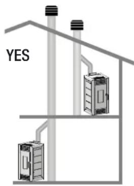
Fig.1: methods for installing the flue
is easily opened and inspected through the air-tight door.
- Whenever flues with parallel exits are used it is advisable to raise the upwind chamber by one element.
- The chimney tube must never pass across a combustible surface.
The Chimney Cap
The chimney cap must respect the following requirements:
- It must have the equivalent diameter and internal form of the flue.
- It must have a useful outlet diameter of not less than double that of the flue.
- The chimney cap on the roof or that remains in contact with the outside (for example, in case of open lofts or attics), must be covered with elements in brick or tile and must, in any case, be well insulated.
- It must be constructed to prevent rain, snow, and extraneous bodies from entering the flue and so that the discharge of the products of combustion is not inhibited by wind from any quarter or strength (windproof chimney cap).
- The chimney cap must be positioned in such a way as to guarantee the adequate dispersion and dilution of the products of combustion and in any case, must be out of the reflux zone. This zone has different dimensions and forms according to the angle of inclination of the roof so it is necessary to adopt minimum heights (Fig. 2).
- The chimney cap must be a wind-proof type and must be above the ridge.
- Eventual structures or other obstacles that are higher than the chimney cap must not be too close to the chimney cap itself.
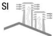
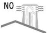
Fig.2: characteristics of the chimney cap
Before you connect the auxiliary pipes for the canalisation of the air, please check that:
• The canalisation system is according to law.
- The system does not present any obstructions.
- Once you connect the stove and use the air ducting, there is a regular air flow at the end of the canalisation.
- You can use up to two hot air delivery pipes with a maximum lenght of 4 m. each. If you use only one pipe, the maximum lenght is 5 m. For more information see chapter 6.0.
- The piping and conduit must be protected with fixed, non-reclosable grids or suitable covers. The minimal section must not be reduced anyway.
Sizing
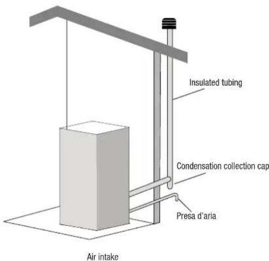
Smoke discharge
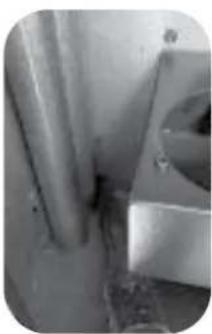
The discharge system must be for the stove only (it is not permissible to discharge into flues in common with other devices). The smoke discharge takes place through the 8 cm diameter tube placed at the back. A "T" with a condensation collection cap should be provided. The smoke discharge of the stove must be connected with the outside using a steel or black tube (resistant up to 450°C) without obstructions.
The tube must be hermetically sealed. To make the tubes airtight and for their eventual insulation, it is necessary to use material resistant up to at least 300^ (silicone or putty for high temperatures). The horizontal sections can be up to 2m long. It is possible to have up to three 90^ curves.
If the smoke duct is outside it must be insulated (Fig.4).
If the smoke duct is inserted in a flue (Fig.3), this must be certified for solid combustibles and if it is larger than 150 mm in diameter, modification is necessary by inserting a tube and sealing the discharge with respect to the parts in brickwork.
It must be possible to inspect all the sections of the smoke duct. If it is a fixed duct it must have openings for inspection and cleaning.
The adjacent locale must not be used as a garage or be a space without ventilation or air exchange, a storage area for combustible material or used for an activity that has a fire hazard. According to the norm UNI 10683/98, the stove must not be in
the same environment where extractors, type B gas devices or in any case, devices that create lower atmospheric pressure in the locale are found.
External air intake
The stove must be furnished with the air necessary to guarantee the regular functioning of the combustion and an environmental well being.
- Be sure that the room where the stove is installed has sufficient aeration and, if necessary, install an air intake duct with a minimum recommended diameter of 50 mm and max length 1.5 m to bring in air from the outside.
- The external air intake must communicate with the stove and positioned so that it is not obstructed. It must be protected with a permanent non-closable grill or other suitable protection provided that the minimum diameter is not reduced.
- The air flow can also be acquired from a locale adjacent to where the stove is installed as long as that flow can freely cross the permanent non-closable openings that communicate with the outside.
- The presence in the local adjacent to where the stove is installed, of other devices in use or of suction devices that cause a contrary draught effect must not create a lower air pressure in the locale than in the outside environment.
- In the adjacent locale the permanent openings must respond to the requisites which are listed in the points above.
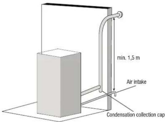
Fig.3: internal flue installation to do according to norms
Positioning
The stove is furnished with an electrical cable to connect to a 230V 50Hz socket, preferably with a thermal-magnetic switch. Variations in tension of more than 10% can compromise the stove (if not already present, an adequate differential switch should be provided). The electrical system must comply with the norms; verify in particular the efficiency of the ground circuit. The electrical feed cable must be of a diameter adequate to the power of the device. The stove must be completely level. Verify the weight bearing capacity of the flooring.
The placement of the stove within the living environment is determined so that the environment is heated in a uniform manner.
Before deciding where to place the stove, keep in mind that:
- The air used for combustion must not come from a garage or a space without ventilation or air exchange, but from a free space or the outside;
• The stove should not be installed in a bedroom; - Rather it is preferable to install the stove in a large, central room of the house to insure the maximum heat circulation; sicurare la massima circolazione del calore;
- A grounded electrical connection is obligatory (if the cable issued with the stove is not long enough to reach the closet socket, use an extension cable along the floor).
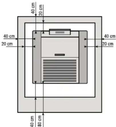
Fire Safety Distance
The stove must be installed respecting the following safety conditions:
- Minimum distance from the sides and the back must be 40 cm from moderately inflammable material;
- Easily inflammable material must not be place closer than 80 cm in front of the stove;
- If the stove is installed on an inflammable pavement the stove must be placed on a slab of material that insulates it from the heat that is wider at the sides by 20 cm and in the front by 40 cm;
- Do not place objects in inflammable material or any material that can compromise the operation of the stove on the stove or within the safety distance;
- In addition, it is advisable to keep all elements of combustible or inflammable material such as beams, wooden furniture, drapes, inflammable liquids, etc. outside the radiance area of the stove, and in any case at least 1m from the heating block (Fig. 8);
- In case of connection to wooden walls or other inflammable material, it is necessary to insulate the smoke discharge tube with ceramic fibre or another material with the
same characteristics.
Fig. 8: minimum distance of objects
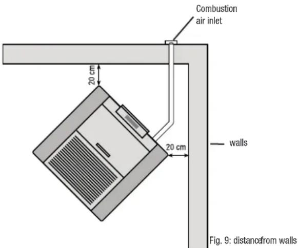
Minimum aeration for comburant air intake
The combustion air must be taken from the outdoor ambience absolutely.
For a correct and safe placement of the air intake all the measures and prescriptions (Fig. 9) must be respected.
There are distances to respect to prevent the comburant air from being subtracted from another source: for example the opening of a window could cause eddies in the outside air subtracting it from the stove.
Lighting
- Before lighting the stove, carefully read the use and maintenance manual.
- Remove from the tank all the tools that were inserted during packaging and be sure that the tank is free of eventual extraneous bodies.
- Unroll the environmental probe placed on the rear of the stove, without placing it on the heated parts of the stove.
- Correctly connect the pellet stove to the flue.
- Fill the tank with 6mm diameter pellets.
- Open the door and check that the basket is properly inserted in its slot and that the
flame trap is located in the upper part of the combustion chamber.
- Close the door. Never open the door while the pellet stove is operating.
- Connect the stove to an outlet with the appropriate cable received with the stove.
- Place the switch on the rear of the stove at the "1" position.
- Press the ON/OFF key for 2 seconds and the gearcase will begin its lighting cycle.
ATTENTION:
During the first lighting it is necessary to ventilate the environment well, since during the first hours of operation unpleasant odours could develop due to fumes from the paint and the grease in the tuyère wrapping.
If during the normal operation of the stove, the temperature of the smoke reaches 220^ C (parameter which can be modified by a technician) the smoke is modulated as follows:
- Smoke removal motor set at the maximum speed;
- Pellet loading gear motor at the minimum speed;
- Tangential heat exchange fan at the maximum speed.
This procedure functions to lower the temperature of the smoke. When this returns below the level of 220^ C the stove will restore the speed of the three motors returning them to the settings before the level was passed.
If the electrical current cuts out, once it is restored, the display will indicate a state of anomaly and will read "Black out". The suction will be increased to expel the residual smoke.
Operations to be performed by the Authorized Assistance Centre every season before the lighting
- A general cleaning inside and outside.
- A careful cleaning of the exchange tubes.
- A careful cleaning and disincrustation of the crucible and the relative cavity.
- Clean the motors, checking the play and fastenings of the mechanisms.
- Clean the smoke channel (substitute the tube gaskets) and smoke extractor fan cavity.
- Clean pressure switch, sostitute silicone tube.
- Check the probe.
- Replace the batteries in the clock on the electronic board.
- Clean, inspect and disincrust the lighting resistor compartment, replacing it if necessary.
- Clean/check the synoptic panel.
- Visually inspect the electrical cables, the connections and the electrical power cable.
- Clean the pellet container and verify the play with the screw feeder gear motor.
- Replace the door seals.
- Test functions, loading the screw feeder, lighting, 10 minutes of operation and shut down.
- Check the electrical parts and the electronic components.
- Check and possible cleaning of the canalisation.
WARNING
- Use of this device is subject to all local and national regulations as well as European regulations.
- The installation of this device is subject to all local and national regulations as well as European regulations.
- Do not pour the Pellets directly into the brazier
- To load the Pellets, open the tank lid positioned on the upper part of the stove and carefully empty the Pellets' package inside.
- Before pouring the Pellets inside the tank, please make sure that the stove is turned off.
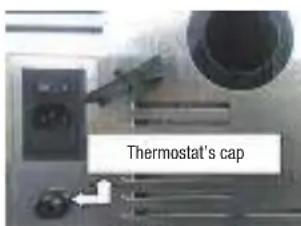
- Should the stove overheat, a safety device will engage and block the feeder mechanism. After the stove's cool-down cycle has been completed, re-engage the thermostat placed at the back of the stove, by removing the thermostat's cap and pressing the button underneath. In case of repeated malfunctions, please contact authorized technical support.
- The device is not intended for users (children included) whose physical or mental abilities are reduced or by users who lack the proper knowledge or experience, unless they have been instructed by a person responsible of their safety on the proper use of this device and all the security measures. Children have to be supervised so that they do not play with the device.
- Use only Pellets recommended by the manufacturer, of a diameter not exceeding 6mm and a length not exceeding 30mm.
- Please store the Pellet in a dry environment.
Instructions
Dear Client,
We thank you for having chosen one of our products, the fruit of technological experience and of continual research for a superior quality product in terms of safety, dependability, and service.
In this manual you will find all the information and useful suggestions to use your product with the maximum safety and efficiency.

Please remember that the first lighting of the stove must be handled by our Authorized Assistance Centre (Law 37/2008) who will check the installation and complete the guarantee.
- Incorrect installation, incorrectly performed maintenance, improper use of the product release the manufacturer from every eventual damage derived from the use of the stove.
- The unit cannot be used as an incinerator. Do not use fuels other than pellets.
- This manual has been realized by the manufacturer and constitutes an integral part of the product and must remain with it during its entire lifetime. If the product is sold or transferred, be sure that the booklet is present since the information contained in it are addressed to the buyer, and to all those persons of various titles who complete the installation, use and maintenance.
- Carefully read the instructions and the technical information contained in this manual, before proceeding with the installation, use, and any operation on the product.
- The observance of the indications contained in the present manual guarantees the safety of people and the product, the economy of use and a longer functioning lifetime.
- Although the carefully studied design and the risk analysis done by our company has permitted the realization of a safe product, in any case, before effecting any operation on the stove, it is recommended to keep said manual available and pay scrupulous attention to the instructions written therein.
- Be very careful when moving the ceramic details where present.
- Check the precise flatness of the pavement where the product will be installed
- The wall where the product will be placed must not be constructed in wood, or in any case, made of an inflammable material, and in addition it is necessary to maintain a safety distance.
- While the stove is in operation, several parts of the stove (door, handle, sides) can reach high temperatures. Therefore pay attention and use the proper precautions, above all in the presence of children, elderly or disabled persons, and animals.
- Assembly must be performed by authorized persons (Authorized Assistance Centre).
- Diagrams and drawings are furnished for the purpose of illustration; the manufacturer, with the intent of pursuing a policy of constant development and renewal of the product can, without any notice, make any modifications that are believed opportune.
- When the stove is working at its maximum speed, it is strongly suggested to wear gloves while handling with the door for pellets loading and the door handle.
• Installation is not recommended in a bedroom.

Never cover the body of the stove in any way or obstruct the openings placed on the upper side when the device is operating. All our stoves are trial lighted on the construction line.
In the event of a fire, disconnect the power supply, use an extinguisher and call the fire fighters if necessary. After that contact the Authorised Assistance Centre.
1.0 Norms and declarations of conformity
- Our company declares that the stove conforms to the following norms for EC European Directive marking.
• 2014/30/EU, Electromagnetic Compatibility Directive (EMCD)
• 2014/35/EU, Low Voltage Directive (LVD) - 2011/65/EU, Restriction of the use of certain Hazardous Substances in electrical and electronic equipment (RoHS Directive)
• Regulation of the CPR (EU 305/2011). - For installation in Italy refer to the UNI 10683/98 or successive modifications; the technician installing the hydrothermal sanitary system will issue the declaration of conformity according to L. 37/2008. The installation of appliance has to be in accordance with local and national laws and with European norms.
- EN 55014-1; EN 55014-2; EN 61000-3-2; EN 61000-3-3; EN 60335-1; EN 60335-2-102; EN 62233; EN 50581; EN14785
1.1 Safety Information
Please carefully read this use and maintenance manual before installing and operating the stove!
If clarification is needed, please contact the dealer or the Authorized Assistance Centre.
- The pellet stove must only be operated in living environments. This stove, being controlled by an electronic board, permits a completely automatic and controlled combustion; the exchange, in fact, regulates the lighting phase, 5 power levels and the shut down stage, guaranteeing the safe operation of the stove.
- The basket used for combustion allows most of the ash produced by the combustion of the pellets to fall into the collection compartment. Nevertheless, check the basket daily, given that not all pellets have high quality standards (use only quality pellets re-
commended by the manufacturer).
- The glass is equipped with a special circulation of air for self-cleaning, but still, it is not possible, after several hours of operation, to keep a light grey patina from forming on the glass. This also depends on the type of pellets used. Some pellets deposit more ash than others.
1.2 Responsibility
With the delivery of the present manual, we decline all responsibility, both civil and penal, for accidents deriving from the partial or total lack of observance of the instructions contained herein.
We decline every responsibility derived from improper use of the stove, from incorrect use by the user, from unauthorized modifications and/or repairs, from the use of replacement parts that are not original for this model.
The manufacturer declines every civil or penal, direct or indirect responsibility due to:
- Lack of maintenance;
- Failure to observe the instructions contained in the manual;
- Use in non-conformity with the safety directives;
- Installation in non-conformity with the norms in force in the country;
• Installation by unqualified or untrained personnel; - Modifications and repairs not authorized by the manufacturer;
- Use of non-original replacement parts;
- Exceptional events.

- The stove must only be fed with quality 6mm diameter pellets of the type recommended by the manufacturer;
- Before making the electrical connection of the stove the discharge tubes must be connected with the flue;
- The protective grill placed inside the pellet container must never be removed;
- The environment where the stove is installed must have a sufficient exchange of air;
- Never open the door of the stove while it is operating;
- When the stove is operating, the surfaces, glass, handle and tubes become very hot: during operation do not touch these parts without adequate protection;
- Keep/store the pellets in a cool dry place;
- Keep the fuel and other inflammable materials off the stove.
- Failure to carry out maintenance or maintenance not carried out as stated in this manual may cause danger and harm to persons or property.
2.0 Stove panel and remote control
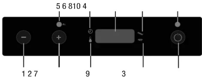
1) Temperature / working power decrease: Using the key on the menu Set temperature, you can decrease the temperature from a max. value of 40^ C to a min. value of 7^ C. With the key on the menu Set power, you can decrease the working power from a max. value of 5 to a min. value of 1.
2) Temperature / working power increase: the key on the menu Set temperature, you can increase the temperature from a min. value of 7^ C to a max. value of 40^ C. With the key on the menu Set power, you can increase the working power from a min. value of 1 to a max. value of 5.
3) Key On/Off: Keep the key pressed off 2 seconds to
4) LED ON/OFF: This led indicates the different phases of the stove:
- it is on if the stove is switched on and working
- it is off if the stove is switched off
- it blinks if the stove is switching off
5) LED AL F: The led blinks in the event of a malfunction or alarm.
6) LED chrono-thermostat: This means the automatic single or daily programming of the switching on or off of the stove is on. The automatic programming can be set with the remote control (optional) or with the control board.
7) LED temperature ok: This is on when the stove reaches the set temperature. In this case you will read the word "Eco" and the set temperature on the display.
8) LED pellets loading: This led blinks every time the stove is loading pellets.
9) LED resistance: This led is on only while the stove is lighting up in order to indicate that the resistance is warming the air which will fire the pellets.
10) Display LED 7 segments: On the display you can read the different working functions of the stove, the room temperature and the set working power. In the event of a malfunction, the display shows the relative error codes (see paragraph on alarm codes).
2.1 Stove setting
How to change the wished room temperature
Join the following procedure to change the wished temperature:
Press the key ⏻ (1) once to enter the menu and set temperature.
You will read the word "Set" and the wished temperature on the display.
Use the keys - (2) e + (3) to increase or reduce the wished value.
The stove will leave the menu Set temperature automatically as soon as you do not work on it for some seconds.
How to change the working power
Join the following procedure to change the working power:
Press the key + (1) once to enter the menu and set the working power. You will read the word "Pot" and the range of 5 possible powers on the display.
Use the keys - (2) and + (3) to increase or reduce the wished value.
The stove will leave the menu Set working power automatically as soon as you do not use it for some seconds.
2.2 Remote control functions
Certain stove adjustment and check functions are accessible solely via the multifunction remote control.
TURBO function.
Press the TURBO key on the remote control to enable the function. The display does not signal the enabling of this function when the stove is off.
During the heating phase the stove goes to maximum and the temperature set point goes to 30° for 30 minutes. At the end of the preset time the stove resumes running at the set power and temperature set point. During the heating phase the stove signals this function by displaying "Turb" alternated with other displays.
SLEEP function.
Press the SLEEP key on the remote control to enable the function. The display does not signal the enabling of this function when the stove is off.
After 60 minutes of heating, this function reduces the temperature setting by 1°C to enable the stove to use less energy. During the heating phase the stove signals this function by displaying "Slee" alternated with other displays.
AUTO function.
Press the AUTO key on the remote control to enable the function. The display does not signal the enabling of this function when the stove is off.
During the heating phase, the stove regulates the heating power proportionally as the temperature set point gets closer. During the heating phase the stove signals this function by displaying "Auto" alternated with other displays.
ECO function.
Press the ECO key on the remote control to enable the function. The display does not signal the enabling of this function when the stove is off.
During the heating phase the stove lowers the heating power every 10 minutes until the minimum is reached. During the heating phase the stove signals this function by displaying "Eco" alternated with other displays.
3.0 Turning on the stove
3.1 Suggestions
Do not continuously turn the stove on and off as this could provoke sparks that could shorten the life of the electrical components.
- Do not touch the stove with wet hands: the stove has electrical components that could produce sparks if handled incorrectly. Only authorized technicians can resolve possible problems.
- Do not remove any screws from the fire chamber without first lubricating them well.
- Never open the glass door of the pellet stove while the stove is in operation.
- Be sure that the brazier basket is positioned correctly.
- The flue system must be suitable for inspection. If it cannot be removed, it must have some holes for inspection and cleaning.
3.2 How to load pellets in the tank
You can load pellets in the tank through the door on the upper part of the stove. Join the following procedure to load pellets:
- Open the door on the upper part of the stove;
- Load the wished pellets quantity with caution (load enough pellets to grant a sufficient functioning of the stove);
- Close the door.

ATTENZIONE:
the furnace and ash drawer must be cleaned every day and prior to each powering-on. Cleaning must consist in the complete removal of all residue.
Failure to clean or incorrect cleaning may cause danger and harm. Do not re-use the pellet possibly remained in the brazier due to no starting-up.
3.3 Lighting
- Fill the container 3/4 full with the pellets recommended by the manufacturer;
- Connect the stove to an electrical outlet with the cable that has been supplied;
- Press the lighting switch located on the back part of the stove;
- The upper display will read "OFF";
- Press the button ⏻ for 2 seconds. After a few moments the smoke extractor and the lighting resistor will start and the display will read "ACC."; the led resistance is switched on.
- After 1 minute the display will read "LOA STOPEL will load the pellets and continue lighting the resistor;
- Once the appropriate temperature has been reached the display will read "FIRE STAB. this means that the stove has begun the last phase in lighting, at the end of which the stove will be completely operational; the led resistance is switched off.
- After several minutes of ventilation the display will read "ON 1-2-3-4-5" and the room temperature, according to the power that has been programmed;
- Once the programmed temperature is reached the display will read "ECO" and the room temperature;
- The temperature led lights when the programmed temperature is reached;
GB
7.0 Cleaning and maintenance
Before effecting any maintenance operation or cleaning on the stove, take the following precautions:
- Be sure that all parts of the stove are cold.
- Be sure that the ashes are completely cold.
- Be sure that the general switch is in the "OFF" position.
- Be sure that the plug is pulled out of the socket to avoid accidental contact.
- Once the maintenance phase is completed check that everything is in order as per before the intervention (the brazier is placed correctly).

Follow carefully the following cleaning instructions. Failure to follow these instructions could create problems with the operation of the stove.
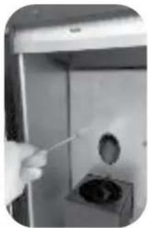
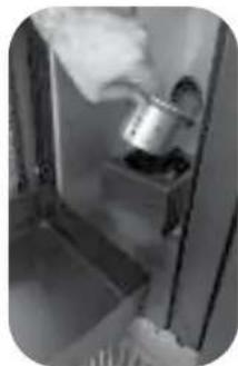
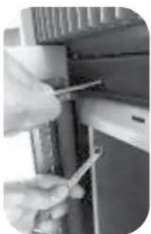
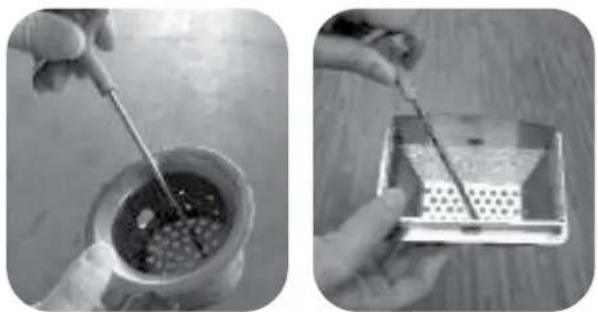
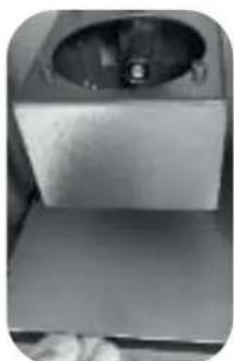
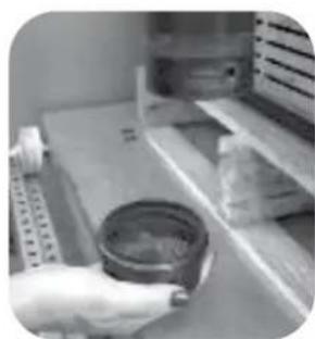
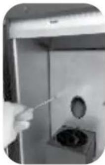
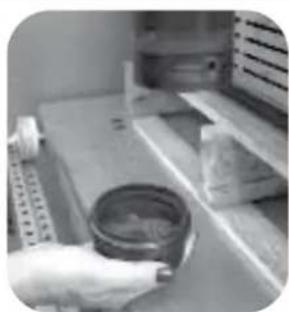
7.1 How to clean the combustion chamber for models ES/ESP 11-13 (once a month)
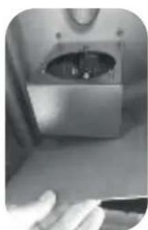
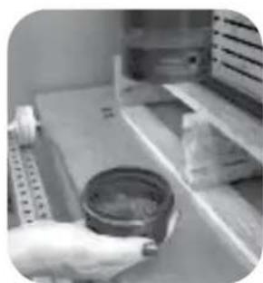
- open the door and remove the brazier and the ash tray (fig. 1)
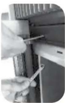
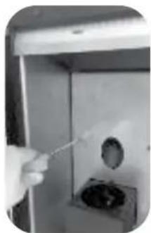
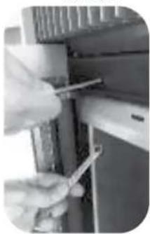
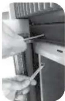
- unscrew the 2 screws in the central bulkhead (fig. 2)
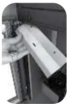
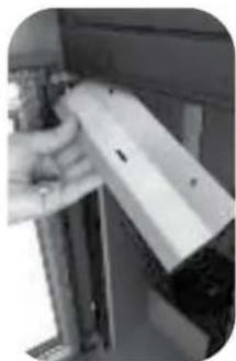
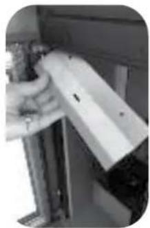
- pull the central bulkhead towards outside and, at the same time, support and take off the fire heater placed on the upper part (fig. 3-4)
- unscrew the 2 screws and remove the flap (fig. 5-6)
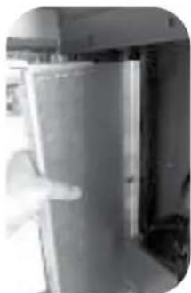
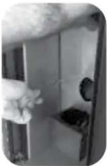
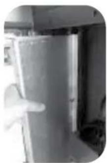
- remove the inside right and left bulkheads pulling outward (fig. 7-8)
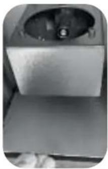
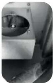
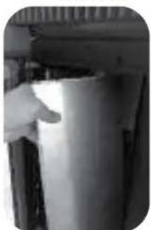
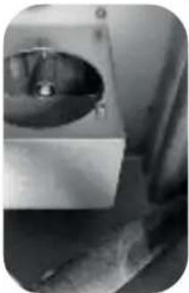
- remove the bottom part pulling up and laterally (fig. 9-10)
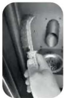
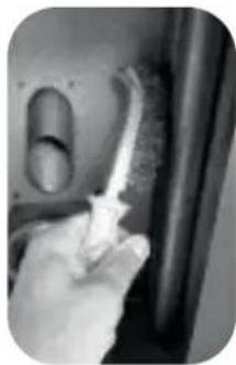
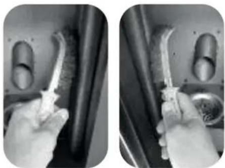
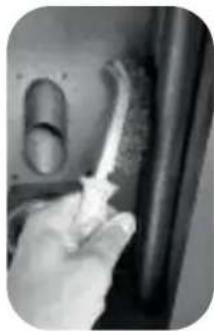
- scrape the inner pipes with a wire brush (fig. 11-12)
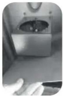
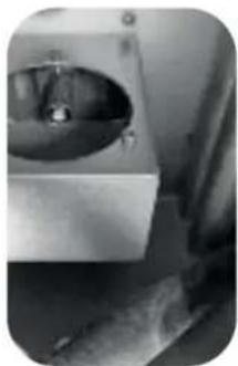
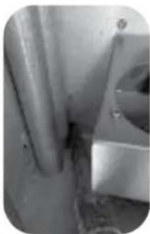
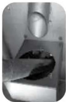
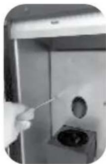
- use a vacuum cleaner to remove the ash from the combustion chamber (fig. 13), behind the exchanger pipes (fig. 14) and inside the brazier (fig. 15)
-do the reverse process to re-assemble.
natural_image
Close-up of a hand holding a small metallic object inside a container (no visible text or symbols)Fig. 1 Fig. 2
natural_image
Hand using a tool to clean or store air quality inside a storage cabinet (no visible text or symbols)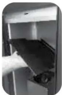
natural_image
Close-up of a hand inserting a dark rectangular object into a white container (no visible text or symbols)Fig. 3 Fig. 4
natural_image
Close-up of a hand using a tool to adjust or install electronic components (no visible text or symbols)Fig. 5 Fig. 6
natural_image
Close-up of a hand holding a white rectangular object with a small protrusion, next to a metal bracket (no visible text or symbols)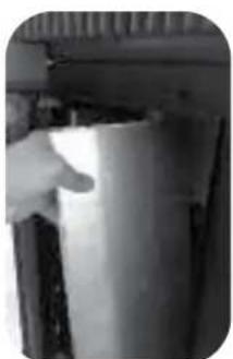
natural_image
Close-up of a hand reaching toward a dark surface, possibly part of a container or mechanical component (no visible text or symbols)Fig. 7 Fig. 8
natural_image
Interior view of a kitchen appliance with a white door and handle (no visible text or symbols)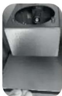
natural_image
Exterior view of a modern office building (no signage)Fig. 9 Fig. 10
natural_image
Close-up of a hand holding a pen near a metallic device with a circular opening (no visible text or symbols)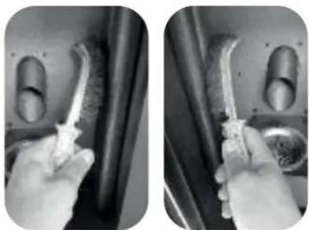
natural_image
Two black-and-white photos showing hands cleaning a wall with a brush and a tool, no visible text or symbols.Fig. 11 Fig. 12
natural_image
Close-up of a mechanical device with a circular component and a handle, possibly a valve or sink (no visible text or symbols)Fig. 13 Fig. 14
natural_image
Close-up of a wall with visible pipes and a circular object, no text or symbols present
natural_image
Close-up of a finger pressing a small object into a rectangular block (no visible text or symbols)Fig. 15
7.3 Cleaning the surfaces
To clean the surfaces, use a rag dampened with water or with water and a neutral detergent.

The use of aggressive detergents or thinners can damage the surfaces of the stove. Before using any detergent it is advisable to try it on a small section out of sight or contact the Authorized Assistance Centre for information regarding the product.
7.4 Cleaning the metal parts
To clean the metal parts of the stove, use a soft cloth dampened with water.
Never clean the metal parts with alcohol, thinners, petrol, acetone or other degreasing substances. If such substances are used, our company declines any responsibility.
Eventual variations in the colour of the metal parts can be caused by an incorrect use of the stove.

ATTENZIONE:
the furnace and ash drawer must be cleaned every day and prior to each powering-on. Cleaning must consist in the complete removal of all residue.
The lack of cleanliness can prevent the starting of the stove, causing damages to the stove itself and to the environment (possible emission of unbrunt material and soot).
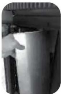
Do not re-use the pellet possibly remained in the brazier due to no starting-up.

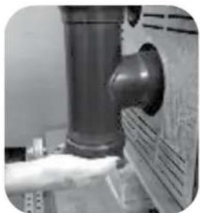
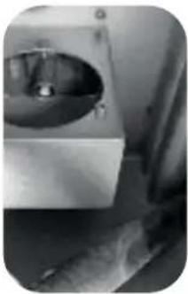
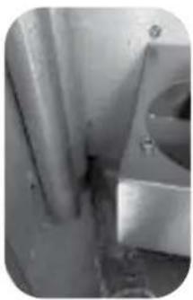
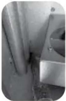
WARNING! Periodically remove and empty the cap of the inspection "T" pipe located behind the stove (see picture 23 and 24). The lack of cleanliness can prevent the starting of the stove, causing damages to the stove itself and to the environment (possible emission of unbrunt material and soot). Do not re-use the pellet possibly remained in the brazier due to no starting-up.
natural_image
Close-up of a hand holding a large cylindrical pipe outlet, no visible text or symbolsFig.23 Fig.24
natural_image
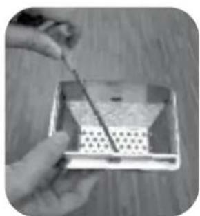
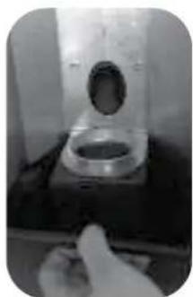
Hand holding a small container on a shelf with shelves of contents and a ruler nearby (no visible text or symbols)7.5 Cleaning the brazier and brazier support
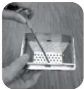
When the flame assumes a red colour or seems weak, and is accompanied by black smoke, this means that there are ash deposits or incrustations that do not permit the correct functioning of the stove and that must be removed (fig. 25a-25b).
Remove the brazier every day by simply raising it from its slot; then clean out the ashes and eventual incrustations that may have formed, paying particular attention to liberating the holes by using a pointed tool (not included with the stove)
This operation is made particularly necessary before every lighting the first several times and above all if using pellets that differ from those supplied by our company. The frequency of this operation is determined by how frequently the stove is used and the choice of pellets. It is also a good idea to check the brazier support, vacuuming the eventual ash present.
natural_image
Two black-and-white photos showing hands using a tool to apply material in a container and a tray with perforated contents (no visible text or symbols)Fig.25a Fig.25b
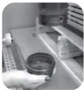
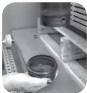
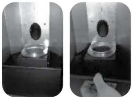
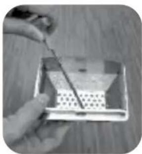
7.7 Ash box
Open the door and extract the ash box (Fig. 26). Use a vacuum to remove all the ash deposited within. This operation must be performed more or less frequently depending on the quality of the pellets used.
natural_image
Two black-and-white photos showing a test tube with a circular opening and a hand holding a sample (no visible text or symbols)Fig. 26
7.8 Cleaning the glass
The glass is a self cleaning type, therefore, while the stove is working, a veil of air is blown across its surface to remove ash and dirt; nevertheless over a period of several hours, a greyish patina tends to form which should be cleaned when the stove is next shut down. How dirty the glass becomes also depends on the quality and quantity of pellets used. Cleaning the glass should be done when the stove is cold with products recommended and tested by our company.
When performing this operation, always check that the grey seal around the glass is in a good state; failure to check the efficiency of this gasket can compromise the function of the stove. Poor quality pellets can, in any case, cause the glass to become dirty.

WARNING!
If the glass is broken, do not attempt to light the stove.
7.9 Cleaning the clearing system
Until a reasonable experience is acquired regarding the operating conditions, it is advisable to perform this maintenance on at least a monthly basis.
- Remove the electrical feed cable;
- Remove the cap from the T-joint and proceed with the cleaning of the ducts. If necessary, at least for the first few times, call in qualified personnel;
- Carefully clean the smoke discharge system: for this, contact a professional chimney sweep;
- Once a year clean the dust, cobwebs, etc. from the zone behind the internal covering panels, paying particular attention to the fans.
7.10 Cleaning the fans
The stove is furnished with fans (environmental and smoke) positioned at the rear and below the stove. Eventual deposits of dust or ash on the blades of the fan can cause an imbalance in the fans leading to noisy performance.
It is, therefore, necessary to clean the fans at least once a year.
Since said operation requires dismantling several parts of the stove, have the fans cleaned only by our Technical Assistance Centre.
7.11 Season end cleaning
At the end of the season, when the stove will not be used for some time, it is advisable to perform a thorough and general cleaning:
- Remove all the pellets from the container and the screw feeder;
- Carefully clean the brazier, the brazier support, the combustion chamber and the ash box.
Once the preceding points have been observed, it only means that the state of the stove has been verified. It is necessary to thoroughly clean the smoke discharge tube or flue and check the condition of the basket. If necessary, order a new one from our Authorized Assistance Centre. If necessary, lubricate the hinges of the door and the handle. Also check the ceramic fibre cord near the glass, on the internal wall of the door; if it is worn or too dry, order a new one from the Authorized Assistance Centre.
8.0 Replacing elements
8.1 Replacing the glass
The stove is furnished with a 4 mm thick ceramic glass that is resistant to a thermal shock of 750^ C; the glass can break only from a strong impact or from improper use.
Do not slam the door or hit the glass.
In case of breakage, replace the glass only with an original replacement furnished by the Authorized Assistance Centre.
9.0 Annual maintenance by the Authorized Assistance Centre
The following operations are to be programmed annually by the Authorized Assistance Centre and are necessary to insure that the product remains efficient and guarantee safe operation.
- Careful cleaning of the combustion chamber;
- Cleaning and inspection of the smoke clearing ducts;
- Checking the seal of the gaskets;
- Cleaning the mechanisms and moving parts (motors and fans);
- Checking the electrical parts and the electronic components.
9.1 Operations to perform every season before the first lighting
- A general cleaning inside and outside;
- A careful cleaning of the exchange tubes;
- A careful cleaning and disincrustation of the crucible and the relative cavity;
- Clean the motors, checking the play and fastenings of the mechanisms;
- Clean the smoke channel (substitute the tube gaskets) and smoke extractor fan cavity;
- Clean silicone tube connected to the pressure switch;
- Clean, inspect and disincrust the lighting resistor cavity, replacing it if necessary;
- Clean/check the synoptic panel;
- Visually inspect the electrical cables, the connections and the electrical power cable;
- Clean the pellet container and verify the play with the screw feeder gear motor;
- Replace the door seals;
- Functional assessment, loading the screw feeder, lighting, 10 minutes of operation and shut down.
Model: MIA 2 - 9
| Heating input (min-max): | 2,09 kW - 8,5 kW |
| Nominal heat output: | 7,64 kW |
| Reduced heat output: | 2,0 kW |
| CO emissions at 13% O2 (nominal heat): | 0,017 % |
| CO emissions at 13% O2 (reduced heat): | 0,014 % |
| Efficiency at nominal heat output: | 89,84% |
| Efficiency at reduced heat output: | 95,48% |
| Flue gas temperature at nominal heat output: | 138,2 °C |
| Flue gas temperature at reduced heat output: | 52,3°C |
| Draught (min-max): | 10-12 Pa |
| Voltage: | 230 V |
| Frequency: | 50 Hz |
| Electrical consumption (ignition): | 280 W |
| Electrical consumption (working): | 100 W |
| Weight (with door): | 83 kg |
Model: MIA 2 - 11
| Heating input (min-max): | 2,09 kW - 10 kW |
| Nominal heat output: | 8,88 kW |
| Reduced heat output: | 2,0 kW |
| CO emissions at 13% O2 (nominal heat): | 0,013 % |
| CO emissions at 13% O2 (reduced heat): | 0,014% |
| Efficiency at nominal heat output: | 88,78% |
| Efficiency at reduced heat output: | 95,48% |
| Flue gas temperature at nominal heat output: | 154,2 °C |
| Flue gas temperature at reduced heat output: | 52,3°C |
| Draught (min-max): | 10-12 Pa |
| Voltage: | 230 V |
| Frequency: | 50 Hz |
| Electrical consumption (ignition): | 280 W |
| Electrical consumption (working): | 100 W |
| Weight (with door): | 83 kg |

WARNING!
In case of fire inside the chimney, immediately contact the firefighters.
natural_image
Diagram of two electrical boxes mounted on a vertical structure with piping (no text or symbols)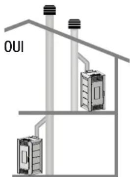
natural_image
Close-up of a mechanical device with a metallic component and transparent casing, partially enclosed in a frame (no visible text or symbols)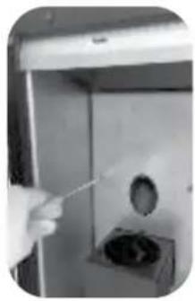
natural_image
Hand using a tool to clean or store contents inside a stainless steel door (no visible text or symbols)Fig. 1 Fig. 2

natural_image
Close-up of a hand holding a small object inside a metallic door (no visible text or symbols)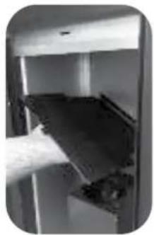
natural_image
Close-up of a hand inserting a dark object into a metallic housing (no visible text or symbols)Fig. 3 Fig. 4
natural_image
Close-up of a hand using a tool to adjust or install electronic components on a shelf (no visible text or symbols)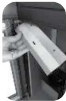
natural_image
Close-up of a hand holding a white mechanical component mounted on a metal frame (no visible text or symbols)Fig. 5 Fig. 6
natural_image
Close-up of a hand opening a door handle (no visible text or symbols)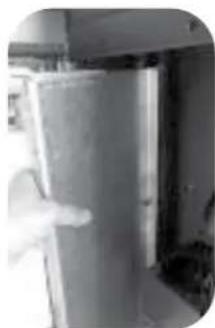
natural_image
Interior view of a refrigerator with visible door and window (no text or symbols)Fig. 7 Fig. 8
natural_image
Close-up of a metallic mechanical component with a circular opening and a flat base (no visible text or symbols)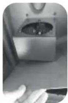
natural_image
Close-up of a hand holding a small object inside a metallic appliance (no visible text or symbols)Fig. 9 Fig. 10
natural_image
Close-up of a hand holding a tool near a curved object, possibly a device or tool (no visible text or symbols)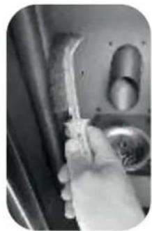
natural_image
Close-up of a hand holding a medical or laboratory instrument inside a vehicle door (no visible text or symbols)Fig. 11 Fig. 12
natural_image
Close-up of a metallic mechanical component with a circular opening and internal cavity (no visible text or symbols)Fig. 13 Fig. 14
natural_image
Close-up of a metallic pipe joint with a circular opening, no visible text or symbols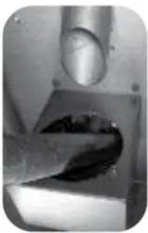
natural_image
Close-up of a metallic tool interacting with a dark, glossy surface (no visible text or symbols)Fig. 15
natural_image
Close-up of a hand reaching toward a large pipe outlet (no visible text or symbols)Fig.23 Fig.24
natural_image
Hand holding a small cylindrical object on a shelf, with shelves and equipment in the background (no visible text or symbols)natural_image
Close-up of a hand using a tool to stir contents in a bowl (no visible text or symbols)Fig.25a Fig.25b
natural_image
Hand holding a tool interacting with a grid-patterned object inside a transparent container (no visible text or symbols)7.7 Cendrier
natural_image
Close-up of a transparent cylindrical object with a central oval, mounted on a base (no visible text or symbols)Fig. 26
natural_image
Close-up of a mechanical component with a circular opening and a rectangular base, no visible text or symbolsnatural_image
Diagram of two electrical cabinets connected to a vertical structure with piping (no text or symbols)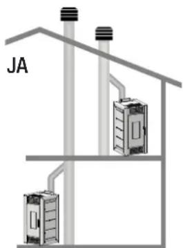
natural_image
Close-up of a hand holding a small metallic object inside a container (no visible text or symbols)Abb. 1 Abb. 2
natural_image
Close-up of a hand holding a tool near a small circular object inside a cabinet (no visible text or symbols)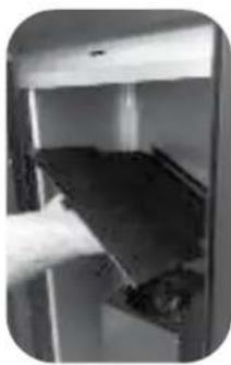
natural_image
Close-up of a hand placing a dark object into a white container (no visible text or symbols)Abb. 3 Abb. 4
natural_image
Close-up of a hand opening a door with a glass door and dark interior (no visible text or symbols)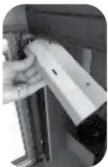
natural_image
Close-up of a hand holding a white rectangular object with metallic legs, possibly a tool or component (no visible text or symbols)Abb. 5 Abb. 6
natural_image
Close-up of a hand using a tool to adjust or install electronic components on a shelf (no visible text or symbols)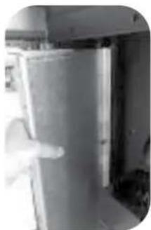
natural_image
Interior view of a kitchen appliance with a door and handle (no visible text or symbols)Abb. 7 Abb. 8
natural_image
Close-up of a hand interacting with a metallic object (no visible text or symbols)
natural_image
Close-up of a hand holding a small electronic device with a metallic panel (no visible text or symbols)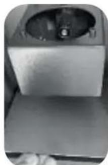
natural_image
Close-up of a metallic mechanical component with a circular dial and base, no visible text or symbolsAbb. 9 Abb.10
natural_image
Two black-and-white photos showing hands cleaning a ceiling fixture with a brush and tool (no text or symbols visible)Abb. 11 Abb. 12
natural_image
Close-up of a mechanical device with a circular component and a handle, no visible text or symbolsAbb. 13 Abb. 14
natural_image
Close-up of a pipe with visible pipes and a small circular object, no text or symbols presentAbb. 15
natural_image
Close-up of a metallic tool interacting with a dark, glossy surface (no visible text or symbols)natural_image
Two black-and-white photos showing hands using a tool to apply material: one in a container with a screwdriver, the other in a tray with a grid-patterned object (no visible text or symbols)Abb. 25a Abb. 25b
7.7 Aschekasten
natural_image
Close-up of a hand opening a pipe fitting into a control panel (no visible text or symbols)Abb. 23 Abb. 24
natural_image
Hand holding a glass jar on a shelf with a ruler and stacked boxes in the background (no visible text or symbols)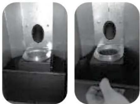
natural_image
Two black-and-white photos showing a test tube with a central vial and a hand holding a sample (no visible text or symbols)Abb. 26
natural_image
Diagram of two electrical enclosure units mounted on a vertical structure, connected by wires (no text or symbols)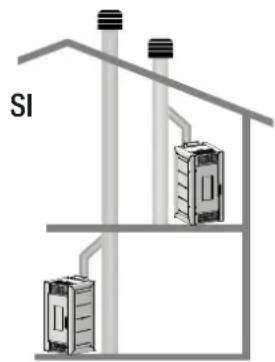
natural_image
Close-up of a metallic object inside a container with a white smoke rising from it (no visible text or symbols)Fig. 1 Fig. 2
natural_image
Hand using a tool to clean or store air quality inside a stainless steel appliance (no visible text or symbols)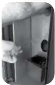
natural_image
Close-up of a hand adjusting a door handle (no visible text or symbols)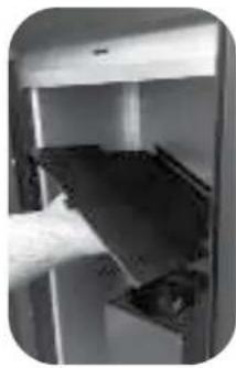
natural_image
Close-up of a hand inserting a dark object into a white cabinet (no visible text or symbols)Fig. 3 Fig. 4

natural_image
Close-up of a hand using a tool to adjust or install electronic components on a device (no visible text or symbols)Fig. 5 Fig. 6
natural_image
Close-up of a hand holding a white mechanical component with metal brackets (no visible text or symbols)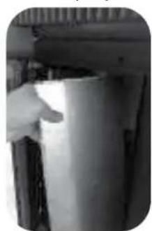
natural_image
Close-up of a hand holding a container in a metal container (no visible text or symbols)Fig. 7 Fig. 8
natural_image
Interior view of a modern kitchen or appliance with a white cloth partially visible (no text or symbols)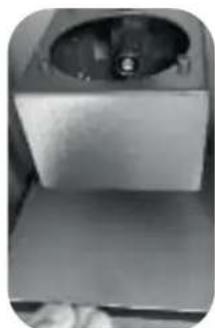
natural_image
Close-up of a metallic mechanical component with a circular opening (no visible text or symbols)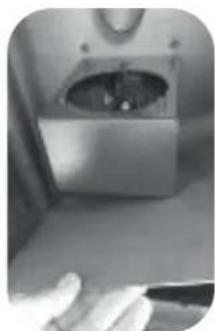
natural_image
Close-up of a hand holding a small electronic device with a circular vent (no visible text or symbols)Fig. 9 Fig.10
natural_image
Close-up of a hand holding a tool near a curved surface, possibly part of a vehicle or industrial component (no visible text or symbols)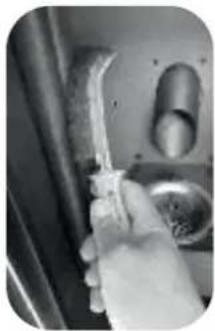
natural_image
Close-up of a hand holding a tool near a door handle (no visible text or symbols)Fig. 11 Fig. 12
natural_image
Close-up of a metallic mechanical component with a circular opening and internal structure (no visible text or symbols)Fig. 13 Fig. 14
natural_image
Close-up of industrial pipes and a mechanical component (no visible text or symbols)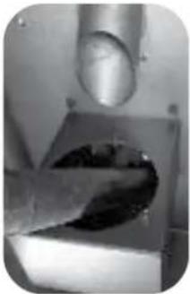
natural_image
Close-up of a metallic tool interacting with a dark, glossy surface on a square base (no visible text or symbols)Fig. 15
natural_image
Close-up of a hand reaching toward a large pipe outlet (no visible text or symbols)Fig.23 Fig.24
natural_image
Hand holding a small cylindrical object on a shelf with shelves of items in the background (no visible text or symbols)natural_image
Close-up of a hand using a tool to stir contents in a container (no visible text or symbols)Fig. 25a Fig. 25b
natural_image
Hand holding a small container with a triangular pattern and a tool, placed on a wooden surface (no text or symbols visible)7.7 Contenedor de cenizas
natural_image
Close-up of a metallic mechanical component with a circular opening, mounted on a base (no visible text or symbols)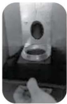
natural_image
Close-up of a laboratory glassware setup with a circular opening and a hand holding a tool (no visible text or symbols)Fig. 26
- Cassetto cenere
- Carefully read the precautions and follow the procedures correctly.
- WARNING!
- Norms and conformity declarations
- Legislation
- Generic danger
- Responsibility
- Installation
- Flue
- The Chimney Cap
- Sizing
- Smoke discharge
- External air intake
- Positioning
- Fire Safety Distance
- Minimum aeration for comburant air intake
- Lighting
- ATTENTION:
- Operations to be performed by the Authorized Assistance Centre every season before the lighting
- WARNING
- Instructions
- Dear Client,
- Please remember that the first lighting of the stove must be handled by our Authorized Assistance Centre (Law 37/2008) who will check the installation and complete the guarantee.
- Never cover the body of the stove in any way or obstruct the openings placed on the upper side when the device is operating. All our stoves are trial lighted on the construction line.
- Norms and declarations of conformity
- Safety Information
- Responsibility
- Stove panel and remote control
- Stove setting
- How to change the wished room temperature
- How to change the working power
- Remote control functions
- TURBO function.
- SLEEP function.
- AUTO function.
- ECO function.
- Turning on the stove
- Suggestions
- How to load pellets in the tank
- ATTENZIONE:
- Lighting
- GB
- Cleaning and maintenance
- How to clean the combustion chamber for models ES/ESP 11-13 (once a month)
- Cleaning the surfaces
- Cleaning the metal parts
- Cleaning the brazier and brazier support
- Ash box
- Cleaning the glass
- Cleaning the clearing system
- Cleaning the fans
- Season end cleaning
- Replacing elements
- Replacing the glass
- Annual maintenance by the Authorized Assistance Centre
- Operations to perform every season before the first lighting
- Cendrier
- Aschekasten
- Contenedor de cenizas
Brand : OLIMPIA SPLENDID
Model : MIA 2 11
Category : Pan