LS2120 - Alarm system ABUS - Free user manual and instructions
Find the device manual for free LS2120 ABUS in PDF.

| Product type | Active infrared detectors with dual pulsed light beam |
| Brand | ABUS |
| Model | LS2120 |
| Dimensions (H x W x D) | 173 x 74 x 72 mm |
| Weight | Approx. 500 g (transmitter + receiver) |
| Power supply | 10-30 V DC (non-polarity) |
| Power consumption (Tx+Rx) | 77 mA |
| Outdoor detection range | 120 m |
| Indoor detection range | 240 m |
| Radiation perimeter | 3.6 m |
| Response time | Adjustable from 50 ms to 700 ms |
| Alarm output (Rx) | Relay NO/NC, 1 A / 120 V AC |
| Tamper output (Tx+Rx) | NC contact, 1 A / 120 V AC |
| Alignment laser | Class 3a, 650 nm, ≤5 mW |
| Operating temperature | -25 °C to 55 °C |
| Protection rating | IP55 |
| Main functions | Long-range surveillance, dual beam, tamper detection, laser and LED adjustment |
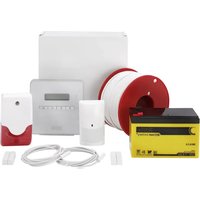
| Package contents | Transmitter, receiver, front covers, mounting plates, pole accessories |
| Safety | Do not open when energized, avoid direct exposure to light, observe temperature ranges |
| Maintenance and cleaning | Clean the front covers regularly, check alignment |
| Spare parts and repairability | Contact a specialized dealer; no user-repairable parts |
Frequently Asked Questions - LS2120 ABUS
User questions about LS2120 ABUS
0 question about this device. Answer the ones you know or ask your own.
Ask a new question about this device
Download the instructions for your Alarm system in PDF format for free! Find your manual LS2120 - ABUS and take your electronic device back in hand. On this page are published all the documents necessary for the use of your device. LS2120 by ABUS.
USER MANUAL LS2120 ABUS
natural_image
Two black ARUS brand speakers standing upright, no visible text or symbols on the device surfacesLS2030 / LS2060 / LS2080 / LS2120
Photoelectric Beam Detector
Installation Instructions (UK) 11
natural_image
Four black-and-white illustrations showing different behaviors: a hand washing clothes, a car spraying water, a car crashing with splashes, and a trash can (no text or symbols)flowchart
graph TD
    A["Bracket A: Box with arrow"] --> B["Bracket B: Box with arrow"]
    B --> C["Bracket C: Box with arrow"]
    style A fill:#f9f,stroke:#333
    style B fill:#f9f,stroke:#333
    style C fill:#f9f,stroke:#333
natural_image
Three technical line drawings of electronic devices with no visible text or symbolsnatural_image
Pure electrical circuit lines without any symbolsnatural_image
Diagram of a multimeter connected to a wall-mounted electrical component, showing wiring and a magnified view (no text or symbols)Photoelectric Beam Detector Installation Instructions
LS2030 / LS2060 / LS2080 / LS2120
1. Preface
Dear Customer,
thank you for purchasing this photoelectric beam detector. This equipment is produced with state-of-the-art technology, which complies with the current standards of domestic and European regulations. The CE has been proven and all related certifications are available from the manufacturer (www.security-center.org) upon request.
To ensure proper and safe operation, it is your obligation to observe these installation instructions!
In the event of questions, please contact your local specialist dealer.
2. General advice
To reduce the risk of electric shock and to ensure that your guarantee remains valid, do not open the equipment when it is in use.
No part of the product may be changed or modified in any way.
The photoelectric beam must only be used within the prescribed temperature and protection class ranges. Using the equipment outside the prescribed ranges results in greater wear and early failure. All required specifications can be found in the technical data.
Avoid greater physical stress of the equipment (knocks, vibrations, etc.). Incorrect handling and bad transport conditions can lead to damage to the equipment.
We want you to work only with products that incorporate state-of-the-art technology. For this reason, we reserve the right to make technical modifications.
We reserve the right to make changes to these instructions without prior notice.
© ABUS Security-Center GmbH & Co. KG, February 2010
3. Main features
- Long detection range
- Reliable detection through pulsed dual beams
- Easy and quick installation through horizontal and vertical angle alignment of transmitter and receiver
- Adjustment by laser beam, LED and measurement of the voltage level
- Adjustable response time (50 ms – 700 ms)
- Relay switching (NC/NO) and LED indication while activated
• Waterproof (IP55) and temperature-resistant for outdoor installations - Applications: Alarm systems, video supervision, lighting, etc. (e.g.: doors, entrance halls, car parks, halls, fence systems)
- Tamper monitoring of transmitter and receiver by front tamper switch
4. Scope of delivery
- Infrared transmitter (Tx) with front cover, housing screw and mounting plate with self-tapping screw
- Infrared receiver (Rx) with front cover, housing screw and mounting plate with self-tapping screw
Accessories for mast mounting:
- 2 x mounting plates
- 2 x mounting brackets
- 6 x roundhead screws M4x10
• 4 x roundhead screws M4x20
5. Description of components
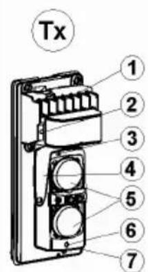
5.1 Transmitter (Tx) and receiver (Rx)
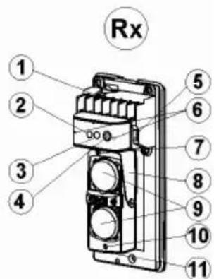
| Transmitter (Tx) Receiver (Rx) | |
| 1. Connectors2. Power LED3. Screw for vertical alignment4. Horizontal alignment5. Lenses | 1. Connectors2. Alarm LED3. Signal LED4. Potentiometer knob for adjusting response time |
| 6. Laser beam for alignment7. Switch for laser beam | 5. Tamper contact6. Contacts for measuring voltage level7. Screw for vertical alignment8. Horizontal alignment9. Lenses10. Laser beam for alignment11. Switch for laser beam |
5.2 Description of connectors
| Transmitter (Tx): Receiver (Rx): | |
| 1/2 Voltage supply 10-30 V DC3/4 NC Tamper output | 1/2 Voltage supply 10-30 V DC3 COM alarm contact4 NC alarm contact5 NO alarm contact6/7 NC Tamper output |
6. Installation
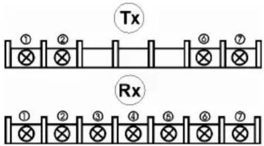
6.1 Important notes
natural_image
Four black-and-white illustrations showing different behaviors: a hand washing clothes, a car spraying water, a car crashing with water, and a trash can (no text or symbols)- Remove all obstacles (plants, washing lines and other objects) between the transmitter and the receiver.
- Avoid direct light or sunshine on the transmitter and receiver.
- Avoid installation where dirt and water can fall directly on the transmitter and receiver.
• Install the transmitter and receiver on a stable, vibration-free surface. - Avoid positioning so that the beams reflect on surfaces or objects.
- Reduce the recommended range if there is a high probability of mist or similar unfavourable weather conditions.
6.2 Position of transmitter and receiver
The recommended installation height for transmitter and receiver is between 0.70 m and 1 m. Both components can be adjusted horizontally (+/-90°) and vertically (+/-15°). This permits flexible installation in the most varied physical conditions (see examples A, B and C).
6.3 Detection range
When installing the photoelectric beams, note the detection range (L) and radiation range (X) of the transmitter.
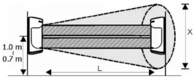
| Model | Detection range L (Outdoo rs) Spread of beams X |
| LS2030 | 30 m 0.9 m |
| LS2060 | 60 m 1.8 m |
| LS2080 | 80 m 2.4 m |
| LS2120 | 120 m 3.6 m |
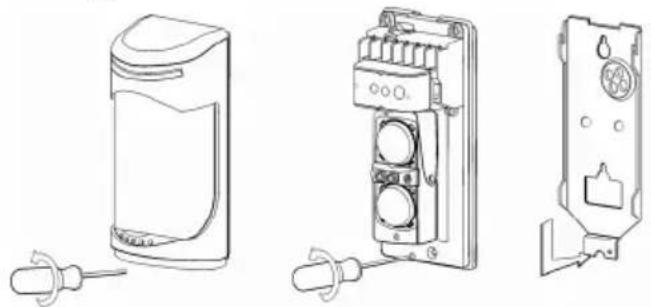
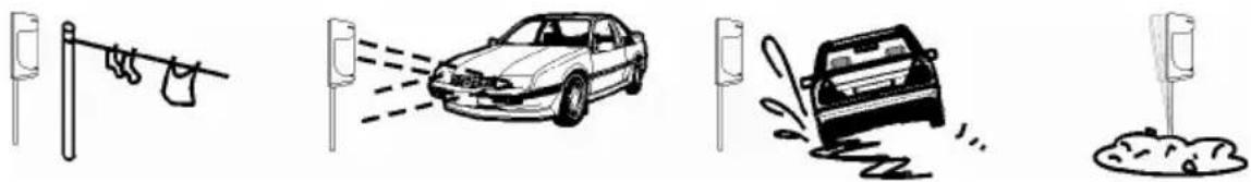
6.4 Wall mounting
natural_image
Technical line drawings of three different electrical components with no visible text or symbols-
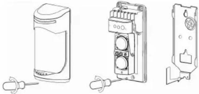
Remove the front cover of the transmitter and receiver by undoing the housing screw.
-
Loosen the base-plates by undoing the fixing screw and remove it
-
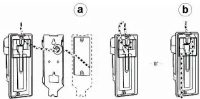
You now have two ways of fixing the connection cable to the rear side. a.) Guide the connection cable through the cable guide on the base-plate. b.) Guide the connection cable through the cable guide of the detector. To do this, remove the predetermined breaking point from the rear of the detector to guide the connection cable through.
-
Now break out the opening for the cable guides on the rear of the transmitter and receiver and connect the cables to the correct connectors.
-
Screw the base-plates to the desired installation locations.
-
Screw the transmitter and receiver to the nase-plates.
-
After connecting the cables to the connectors, go to the "Putting into operation" section.
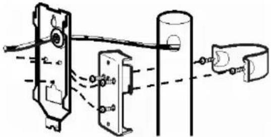
6.5 Pole mounting
natural_image
Pure mechanical assembly diagram showing components connected by rods and a bracket (no text or symbols)- Use a pole with a diameter of 38-45 mm.
- Remove the screwed base-plates of the transmitter and receiver.
- Screw 2 screws M4x20 into the screw-threads of the mounting brackets.
-
Fix the mounting brackets to the masts.
-
Screw the mounting plate with 3 screws M4x10 tightly to the base-plates of the transmitter and receiver.
- Fix the mounting plates to the mounting brackets.
- Repeat steps 3–7 of "Wall mounting".
7. Putting into operation
Before aligning the photoelectric beam, connect the power supply.
You can also connect up the alarm and tamper lines after alignment.
7.1 Rough alignment with laser and LED
Important:
Never look directly into the laser beam! The laser used has a power of <= 5 mW at a wavelength of 650 nm and belongs to Class 3a (classification according to DIN VDI 0837).
- Switch on the laser switch of the transmitter.
- Align the transmitter horizontally and vertically so that the laser beam points to the centre of the receiver. Alignment is optimal when both LEDs of the receiver stop lighting.
- To check: repeat steps 1 and 2 with the laser on the receiver.
The LED on the receiver gives you a first indication of the strength of the received signal.
| Alarm LED (red) and signal LED (yellow) Signal strength | |
| Both LEDs OFF Optimal | |
| One LED ON Adjust | |
| Both LEDs ON Realign | |
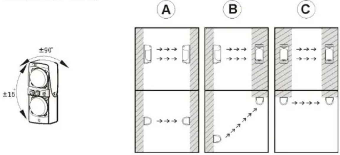
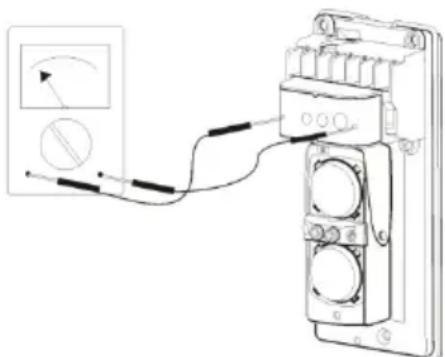
7.2 Fine adjustment by voltage measurement
natural_image
Diagram of a multimeter connected to a terminal block with wires, showing wiring and a magnified inset (no text or symbols)- When the transmitter and the receiver are firmly mounted at the installation location, you can make the fine adjustment of the photoelectric beam by measuring the voltage level.
- Switch your measuring device to the setting "DC" and select the lowest voltage range (0-10 V DC).
-
Measure the voltage on the receiver and compare the value with the table below.
-
Now adjust the horizontal angle of the receiver by hand until the measuring device shows the highest value.
- Turn the adjusting screw to adjust the vertical angle of the receiver until the measuring device shows the highest value.
- Compare the voltage with the values below.
- After achieving a good alignment quality, do not realign the transmitter or receiver again.
| Voltage level Quality of alignment | |
| 5 V – 3.4 V Optimal | |
| 3.4 V – 1.15 V Good | |
| 1.15 V – 1.0 V Sufficient | |
| < 1.0 V Readjust |
7.3 Adjusting the response time
By turning the potentiometer on the receiver, you can change the response time (default 300 ms) of both light beans until an alarm is detected. If the actual response time is shorter than the set response time, no alarm is triggered.
7.4 Putting into operation
- Now close the transmitter and receiver with the front covers.
- Carry out a walk test. Take the response time you set into consideration.
- If required, readjust the Receiver and repeat the walk test.
8. Troubleshooting
| Fault | Possible | reasons | Remedy |
| Power LED on transmitter (Tx) or receiver (Rx) does not light | Incorrectly connected or no power | Check the voltage supply at the connectors | |
| Alarm LED (Rx) does not light when the photoelectric beam is interrupted | – No power– Tx and Rx incorrectly aligned– The photoelectric beams were not interrupted simultaneously | – Check the voltage supply– Clean the front cover– Check the wiring | |
| Photoelectric beams are boken and the alarm LED (Rx) lights, but no alarm is triggered | – Wrong or missing connection of alarm contacts– Relay defect due to over-voltage | Check the connections of the alarm contacts | |
| Alarm LED (Rx) lights permanently | – Tx and Rx incorrectly aligned– Photoelectric beam is interrupted– Front cover is dirty or covered in ice | – Realign Tx and Rx– Remove all obstacles between Tx and Rx– Clean the front cover |
| False triggering of photoelectric beam by leaves, animals, etc. | – Tx and Rx badly aligned– Response tune set too low– Unfavourable environmental influences at installation location | – Realign Tx and Rx– Change the installation location |
9. Technical data
| Detection type | Active infrared photoelectric beam (dual pulsed beams) | ||||
| Max. detection range | Type LS2030 LS2060 | LS2080 L2120 | |||
| Outdoors | 30 m 60 | m 80 m 1 | 20 m | ||
| Indoors | 60 m 120 | m 160 m | 240 m | ||
| Supply voltage | 10 V-30 V DC (without polarity) | ||||
| Power consumption | Type LS2030 LS2060 | LS2080 L2120 | |||
| Tx+Rx | 65 mA 69 | mA 73 mA | 77 mA | ||
| Response / interruption time | Adjustable: 50 ms – 700 ms | ||||
| Alarm output (Rx) | Relay (NO/NC) 1 A / 120 V AC | ||||
| Tamper output (Tx+Rx) | NC contact 1 A / 120 V AC | ||||
| LED signalling Power L | ED (green: Tx+Rx): Voltage supply connected to transmitter (Tx) and receiver (Rx)Alarm LED (red; Rx): Bad alignment or interrupted photoelectric beamSignal LED (yellow; Rx): Weak IR ray or interrupted photoelectric beam | ||||
| Max. external light strength for frontal irradiation | Light sources < 10000 LuxSunshine < 30000 Lux | ||||
| Laser | Wavelength 650 nm; power <= 5 mW; Laser class 3a (classification according to DIN VDI 0837) | ||||
| Ambient operating temperature | -25°C to 55°C | ||||
| Protection class | IP55 | ||||
| Dimensions | 173x74x72 mm (hxbxd) | ||||
natural_image
Four black-and-white illustrations showing different behaviors: a hand washing clothes, a car spraying water, a car crashing with water, and a trash can (no text or symbols)flowchart
graph TD
    A["Shaded Area"] -->|→→→| B["Shaded Area"]
    B -->|→→→| C["Shaded Area"]
    C -->|→→→| D["Shaded Area"]
    D -->|→→→| E["Shaded Area"]
    E -->|→→→| F["Shaded Area"]
    F -->|→→→| G["Shaded Area"]
    style A fill:#f9f,stroke:#333
    style B fill:#f9f,stroke:#333
    style C fill:#f9f,stroke:#333
    style D fill:#f9f,stroke:#333
    style E fill:#f9f,stroke:#333
    style F fill:#f9f,stroke:#333
natural_image
Line drawings of three different electronic devices with no visible text or symbolsnatural_image
Pure mechanical assembly diagram showing components connected by rods and a bracket (no text or symbols)natural_image
Diagram of a mechanical or electrical component with wires and a magnified inset showing a circular symbol (no text or labels)natural_image
Illustration of a car emitting exhaust from a vertical spray can (no text or symbols)
natural_image
Cartoon illustration of a car with motion lines indicating speed or crash (no text or symbols)
| Model | Detectiebereik L (buiten) | Stralingsbereik X |
| LS2030 | 30 m 0,9 m | |
| LS2060 | 60 m 1,8 m | |
| LS2080 | 80 m 2,4 m | |
| LS2120 | 120 m 3,6 m |
6.4 Wandmontage