
Ulisse Radical - Surveillance Camera Videotec - Free user manual and instructions
Find the device manual for free Ulisse Radical Videotec in PDF.
| Product type | Outdoor PTZ surveillance camera |
| Brand | Videotec |
| Model | Ulisse Radical |
| Maximum resolution | Full HD 1080p (1920x1080), 60 fps |
| Sensor | CMOS 1/2.8", 2 megapixel |
| Optical zoom | 33x (15.2-500mm, F3.0) |
| Minimum illumination | Color: 0.041 lux; B/W: 0.005 lux |
| LED projector range | Up to 300 m (with 2 UPTIRN projectors) |
| Horizontal viewing angle | 20.51° (wide) to 0.65° (tele) |
| Vertical viewing angle | 11.58° (wide) to 0.36° (tele) |
| Pan range | Continuous, speed 0.02°/s to 20°/s |
| Tilt range | -20° to +45°, speed 0.02°/s to 20°/s |
| Positioning accuracy | 0.02° |
| Power supply | 24Vac, 120Vac or 230Vac depending on version |
| Power consumption (projectors off) | 24 W (idle, heater off) to 100 W (moving, heater on) |
| Power consumption (projectors on) | 150 W (min power) to 190 W (max power) |
| Net weight | 30 kg |
| Protection rating | IP66 |
| Operating temperature | -40°C to +60°C (continuous), up to +65°C (brief) |
| Relative humidity | 10% to 95% (non-condensing) |
| Network protocols | ONVIF Profile S, TCP/IPv4, HTTP, DHCP, RTSP |
| Special functions | Wiper, washer, autopan, patrol, presets, VCA, Intelligent Defog |
| Housing material | Aluminum die-cast and technopolymer, epoxy-polyester paint RAL9002 |
| Certifications | CE, EN60950-1, EN62368-1, EN50130-4, FCC Part 15 Class A, IP66, EAC, NDAA |
Frequently Asked Questions - Ulisse Radical Videotec
User questions about Ulisse Radical Videotec
0 question about this device. Answer the ones you know or ask your own.
Ask a new question about this device
Download the instructions for your Surveillance Camera in PDF format for free! Find your manual Ulisse Radical - Videotec and take your electronic device back in hand. On this page are published all the documents necessary for the use of your device. Ulisse Radical by Videotec.
USER MANUAL Ulisse Radical Videotec
Top performance long range HD PTZ camera
EN English - Instruction manual
IT Italiano - Manuale di istruzioni
FR Français - Manuel d'instructions
DE Deutsch - Bedienungsanleitung
RU Pycckn - PykoBOcTBO nO 3KcnnyatauN
ULISSE RADICAL
Top performance long range HD PTZ camera

Contents
1 About this manual 5
1.1 Typographical conventions 5
2 Notes on copyright and information on trademarks 5
3 Safety rules 5
4 Identification. 8
4.1 Product description and type designation 8
4.2 Product marking 8
4.2.1 Checking the markings 8
5 Versions 9
5.1 LED illuminator 9
6 Preparing the product for use 9
6.1 Safety precautions before use 9
6.2 Unpacking 10
6.2.1 Removal of the protective packaging 10
6.2.1.1 Housing opening 10
6.2.1.2 Remove the protective packaging. 10
6.3 Contents 11
6.4 Safely disposing of packaging material 11
6.5 Preparatory work before installation 11
6.5.1 Mounting the bracket 11
6.5.2 Cables management 11
7 Installation 12
7.1 Connection of the cables to the base 12
7.2 Fixing the base to the support 13
7.3 Connector board description 13
7.4 Connection of the power supply line 14
7.4.1 24Vac power line connection 14
7.4.2 120Vac and 230Vac power line connection 15
7.4.3 Connection of the alarm inputs, of the twilight switch and of the relays 15
7.5 Connection of the Ethernet cable 16
7.6 Fixing the upper body 16
7.7 Counterweights installation 16
7.8 LED illuminators installation 17
7.8.1 Counterweight removal 17
7.8.2 Fitting the illuminator on the bracket 17
7.9 Connection of the LED illuminators 18
7.10 LED illuminator activation and adjustment instructions 18
7.10.1 Description of the LED illuminator 18
7.10.2 LED illuminator switching on threshold adjustment 19
7.10.3 LED illuminator power adjustment 19
7.11 Fastening of the wiper blade 20
8 Switching on 20
9 Configuration 21
9.1 Web interface 21
9.1.1 Home Page 21
9.1.2 User Controls page 22
9.1.3 Device Parameters Page 23
9.1.4 Device Statistics Page 24
9.1.5 Network Configuration page 24
9.1.6 User Configuration page 25
9.1.7 Motion Parameters Page 25
9.1.7.1 Autopan Page 26
9.1.7.2 Patrol Page 26
9.1.7.3 Motions Recall Page 26
9.1.8 Preset Parameters page 26
9.1.9 Preset Parameters page (Advanced) 26
9.1.10 Digital I/O Page 27
9.1.11 Washer page 27
9.1.12 Camera Settings page 28
9.1.13 Tools Page 28
9.1.14 Factory Default 29
9.2 VTTunnel 30
9.3 Camera 30
10 Accessories 31
10.1 Washer 31
10.1.1 Washing system connection 31
10.2 Wall mount bracket 32
10.3 Parapet bracket 32
10.4 Power supply with illuminator control 32
11 Maintenance 33
11.1 Fuses replacement 33
12 Cleaning 33
12.1 Cleaning the window and plastic parts 33
13 Information on disposal and recycling 34
14 Troubleshooting 34
15 Technical data 35
15.1 General 35
15.2 Mechanical 35
15.3 Electrical 35
15.4 Communications 35
15.5 Cameras 36
15.6 Lenses 36
15.7 Environment 36
15.8 Certifications 36
16 Technical drawings 37
1 About this manual
Read all the documentation supplied carefully before installing and using this product. Keep the manual in a convenient place for future reference.
1.1 Typographical conventions

DANGER!
High level hazard.
Risk of electric shock. Disconnect the power supply before proceeding with any operation, unless indicated otherwise.

DANGER!
Hot surface.
Avoid contact. Surfaces are hot and may cause personal injury if touched.

DANGER!
Mechanical hazard.
Risk of crushing or shearing.

CAUTION!
Medium level hazard.
This operation is very important for the system to function properly. Please read the procedure described very carefully and carry it out as instructed.

INFO
Description of system specifications. We recommend reading this part carefully in order to understand the subsequent stages.
2 Notes on copyright and information on trademarks
The mentioned names of products or companies are trademarks or registered trademarks.
ONVIF is a trademark of Onvif, Inc.
3 Safety rules

CAUTION! The electrical system to which the unit is connected must be equipped with a 20A max automatic bipolar circuit breaker. This circuit breaker must be of the Listed type. The minimum distance between the circuit breaker contacts must be 3mm (0.1in). The circuit breaker must be provided with protection against the fault current towards the ground (differential) and the overcurrent (magnetothermal).

CAUTION! Hazardous moving parts. Keep fingers and other body parts away.

CAUTION! Device installation and maintaining must be performed by specialist technical staff only.

CAUTION! For continued protection against risk of fire, replace only with same type and rating of fuse. Fuses must be replaced only by service personnel.

CAUTION! TNV-1 installation type. The installation is type TNV-1, do not connect it to SELV circuits.

CAUTION! In order to reduce the risk of fire, only use UL Listed or CSA certified cables with sections greater than or equal to 0.14mm^2 (26AWG).
-
The manufacturer declines all responsibility for any damage caused by an improper use of the appliances mentioned in this manual. Furthermore, the manufacturer reserves the right to modify its contents without any prior notice. The documentation contained in this manual has been collected and verified with great care. The manufacturer, however, cannot take any liability for its use. The same thing can be said for any person or company involved in the creation and production of this manual.
-
Before starting any operation, make sure the power supply is disconnected.
- Be careful not to use cables that seem worn or old.
- Never, under any circumstances, make any changes or connections that are not shown in this handbook. Improper use of the appliance can cause serious hazards, risking the safety of personnel and of the installation.
- Use only original spare parts. Non-original spare parts could cause fire, electrical discharge or other hazards.
- Before proceeding with installation, check the supplied material to make sure it corresponds to the order specification by examining the identification labels (4.2 Product marking, page 8).
-
Installation category (also called Overvoltage Category) specifies the level of mains voltage surges that the equipment will be subjected to. The category depends upon the location of the equipment, and on any surge voltage protection provided. Equipment in an industrial environment, directly connected to major feeders/short branch circuits, is subjected to Installation Category III. If this is the case, a reduction to Installation Category II is required. This can be achieved by use of an insulating transformer with an earthed screen between primary and secondary windings, or by fitting UL listed Surge Protective Devices (SPDs) from live to neutral and from neutral to earth. Listed SPDs shall be designed for repeated limiting of transient voltage surges and the following rated operation conditions: Type 2 (SPDs permanently connected to the power network and intended for installation on the load side of the service equipment); Nominal Discharge Current (In) 20kA min. For example: FERRAZ SHAWMUT, STT2240SPG-CN, STT2BL240SPG-CN rated 120Vac/240Vac, (In = 20kA) . Maximum distance between installation and reduction is 5m .
-
This device was designed to be permanently secured and connected on a building or on a suitable structure. The device must be permanently secured and connected before any operation.
- A power disconnect device must be included in the electrical installation, and it must be very quickly recognizable and operated if needed.
- The separate protective earthing terminal provided on this product shall be permanently connected to earth.
- Connect the device to a power source corresponding to the indications given on the marking label. Before proceeding with installation make sure that the power line is properly isolated. The supply voltage should never exceed the limit (± 10%) .
- Power supply must be provided with a SELV type, 24Vac, 8A isolated source derived from a double isolation UL Listed transformer specially protected in output.
- The appliance includes moving parts. Make sure that the unit is positioned where it is inaccessible under normal operating conditions.
- Attach the Dangerous Moving Parts label near the device. (Fig. 3, page 9).
- Do not use the appliance in the presence of inflammable substances.
-
To connect the power supply line use the appropriate junction-box (UPTJBUL). For further information, refer to the product use and installation manual.
-
Do not allow children or unauthorised people to use the appliance.
- Only skilled personnel should carry out maintenance on the device. When carrying out maintenance, the operator is exposed to the risk of electrocution and other hazards.
- Use only the accessories indicated by the manufacturer. Any change that is not expressly approved by the manufacturer will invalidate the guarantee.
- Before connecting all the cables make sure the device is properly connected to the earth circuit.
- If the device has to be removed from the installation, always disconnect the earth cable last.
Take all necessary precautions to prevent the apparatus from being damaged by electrostatic discharge.
- The unit has been made for connection using a 3-pole cable. To make a correct connection to the earth circuit, follow the instructions in this handbook.
- Handle the unit with great care, high mechanical stress could damage it.
- Make especially sure that the power supply line is insulated at a sufficient distance from all the other cables, including lightning protection devices.
- If it is necessary to transport the device, this should be done with great care. Abrupt stops, bumps and violent impact could damage the unit or injure the user.
4 Identification
4.1 Product description and type designation
ULISSE RADICAL is the first PTZ Full HD Videotec network system ready for use that integrates exceptional lens and pre-configured camera combinations, Full HD 1080p, 60fps and CMOS 1/2.8" sensors, for night and day broadcast quality video in extensive outdoor areas.
To meet more specific video surveillance needs, the PTZ unit is equipped with a 33x lens with advanced autofocus which allows and automatically maintains focus on a subject that is very far away with clear details.
ULISSE RADICAL is certified ONVIF Profile S and is compatible with most VMS on the market.
The Videotec's PTZ ASSISTANT plug-in software supports any VMS with the control of all special functions such as wiper, washer pump, IR and Auto Focus.
Powerful motors guarantee exceptionally smooth tracking, even at a minimum speed of 0.02^ / sec .
The performance remains optimal in complete darkness thanks to powerful LED illuminators that can reach distances of over 300m (985ft) with two UPTIRN illuminators (10^, 850nm)
ULISSE RADICAL with 33x zoom features a Thermal Compensation System and a Visible Cut Filter.
Due to its characteristics of accuracy, reliability and robustness, this PTZ camera is the ideal solution for the visual control of large outdoor areas, such as: border patrol, harbour surveillance, long distance perimeter surveillance, traffic and highway control, military installations.
4.2 Product marking

The product has a label applied in compliance with CE marking.

Fig. 1
The label shows:
- Model identification code (Extended 3/9 bar code).
Supply voltage (Volt).
Frequency (Hertz). - Current consumption (Amps).
Protection degree (IP). - Serial number.
4.2.1 Checking the markings
Before proceeding further with installation, make sure the material supplied corresponds to the order specification by examining the marking labels.
Never, under any circumstances, make any changes or connections that are not shown in this handbook. Improper use of the appliance can cause serious hazards, risking the safety of personnel and of the installation.
5 Versions
5.1 LED illuminator

The version with LED illuminators can only powered at 24Vac.
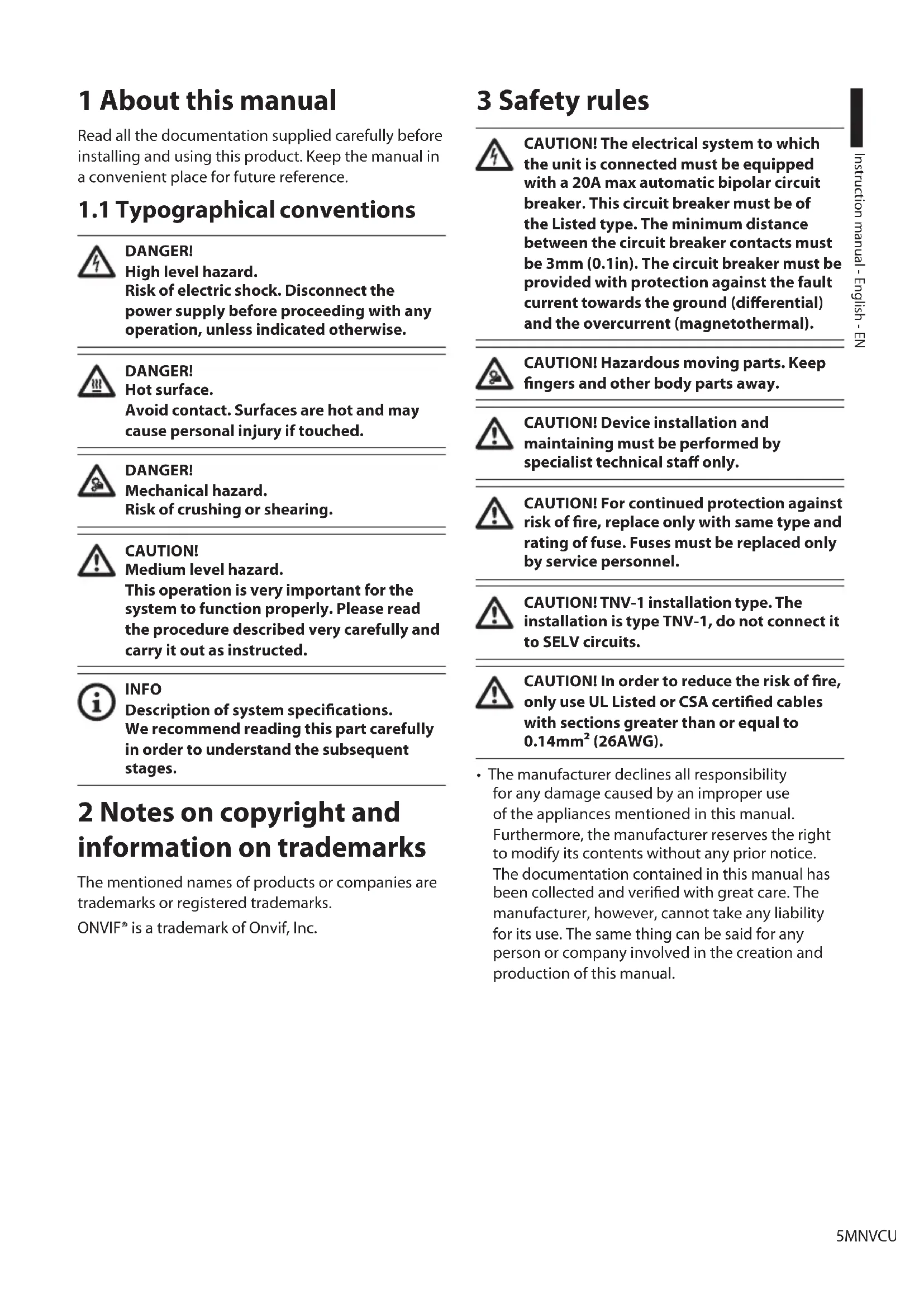
The pan & tilt can be fitted with bracket for 2
VIDEOTEC LED illuminators for night surveillance
(illuminators not included).

Fig. 2
For further information refer to the relative chapter (7.8 LED illuminators installation, page 17).
6 Preparing the product for use

Any change that is not expressly approved by the manufacturer will invalidate the guarantee.

The product must not be dismantled or tampered with. The only exceptions are those concerning the assembly and maintenance operations stipulated in this manual.
6.1 Safety precautions before use

The appliance includes moving parts. Make sure that the unit is positioned where it is inaccessible under normal operating conditions. Attach the warning label supplied with the appliance, placing it near the unit so that it can be seen easily.
Fig. 3
ATTENZIONE!
Hazardous moving parts. Keep fingers and other body parts away.
AVERTISSEMENT!
When the product is delivered, make sure that the package is intact and that there are no signs that it has been dropped or scratched.
If there are obvious signs of damage, contact the supplier immediately.
When returning a faulty product we recommend using the original packaging for shipping.
Keep the packaging in case you need to send the product for repairs.

Unpack the sunshield of the device, taking care not to damage the housing.
6.2.1 Removal of the protective packaging
Remove the protective packaging before installing the device.
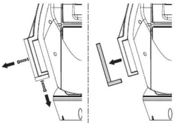
6.2.1.1 Housing opening
Loosen the leak-proof screws placed on the sides and lift the upper part of the housing.
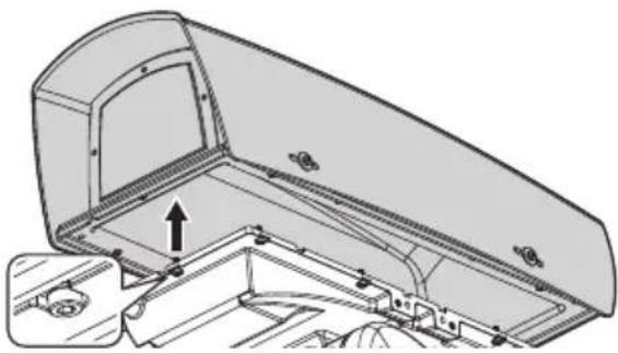
Fig. 4
First of all tighten the two central screws as shown in figure.
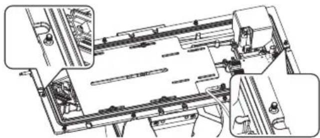

Fig. 5
After installation and wiring, close the product.
6.2.1.2 Remove the protective packaging
Open the housing and remove the protective packaging.
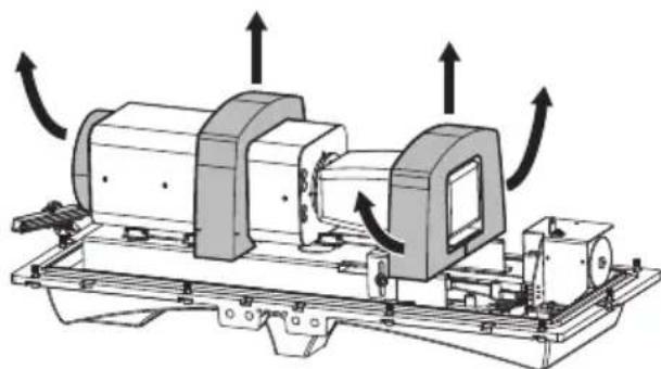
Fig. 6
6.3 Contents
Check the contents to make sure they correspond with the list of materials as below:
- Positioning unit
- Power supply base
-
Accessories package:
-
Serial adaptor
- Serial extension cable
-
Allen wrenches
-
Spacers
Label
Cable ties
Ferrite
Silicone sheath - Reduction gaskets for cable glands
- Instruction manual
- Attachment plate for desiccant bag
- Bolts and screws
Counterweights package:
Counterweights
Counterweights brackets
Sunshield
- Tool kit for washing system mounting (WASPT):
- Nozzle support with screws (nozzle and pipes are included in the washing kit)
6.4 Safely disposing of packaging material
The packaging material can all be recycled. The installer technician will be responsible for separating the material for disposal, and in any case for compliance with the legislation in force where the device is to be used.
6.5 Preparatory work before installation
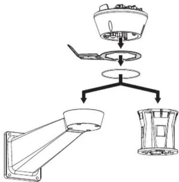
6.5.1 Mounting the bracket

For installations subject to vibrations, only use the parapet bracket.
Different types of supports are available (10 Accessories, page 31). Choose a suitable bracket for the installation and follow all the instructions in the suggested chapter.

Take special care when attaching and fastening down the apparatus. The fastening system must be capable of supporting at least 4 times the weight of the entire equipment.

The device should be assembled vertically. Any other position could impair the performance of the appliance.

Do not attach the device upside down.
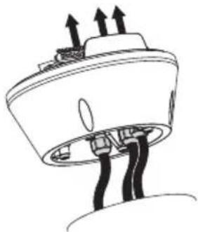
6.5.2 Cables management

The connection cables should not be accessible from the outside.

The cables must be adequately fastened to the structure to avoid the excessive weight causes accidental removal.

You must use cables suited to the type of installation.
Insert the cables into the support so that they protrude by about 50cm
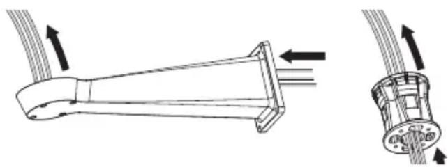
Fig. 7
7 Installation

Never, under any circumstances, make any changes or connections that are not shown in this handbook. Failure to follow the connection instructions that are given in the handbook may create serious safety hazards for people and for the installation.

Do not change the wiring in the product as it is supplied to you. Failure to follow this instruction may create serious safety hazards for people and for the installation, and will also invalidate the guarantee.

If using the washer kit, the nozzle support should be installed before positioning the pan & tilt and the wiring. For further explanations see the specific handbook for the kit.

Fig. 8

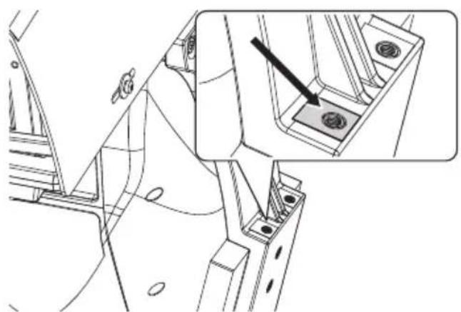
Inside the bottom cover there is a desiccant bag that is used to prevent moisture formation in the base and near the connector boards. Remove the bag before installation.
7.1 Connection of the cables to the base
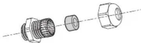
Insert the cables into the cable glands holding the base at about 20cm from the support. Tighten the cable glands. The cable glands are suitable for cables with a diameter between 5mm and 10mm .
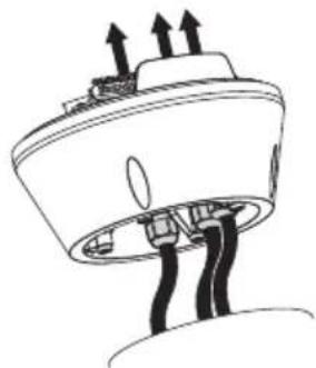

Fig.9
Pay attention to the fixing. Tightening torque: 5Nm.

For cables diameter from 3mm to 7mm use the supplied gaskets.
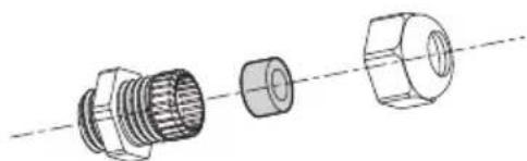
Fig. 10
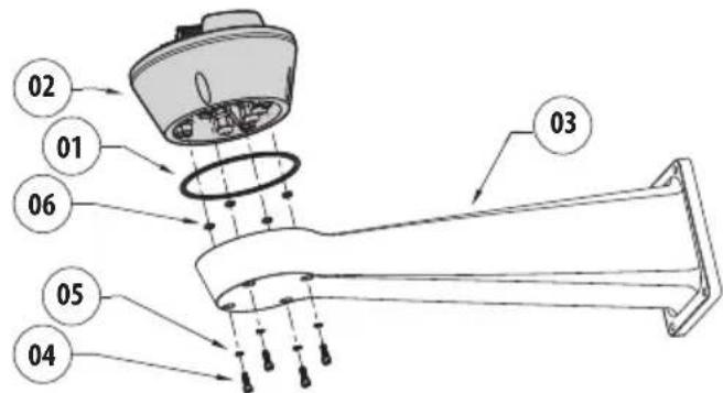
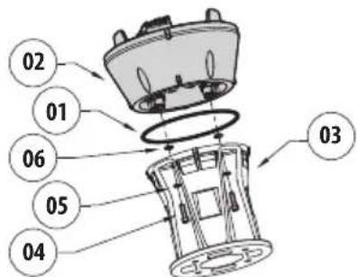
7.2 Fixing the base to the support

Use the screws and the washers supplied with the base.
Once you have positioned the gasket (01), fix the base (02) onto the bracket (03) with screws (04), serrated washers (05) and screw rings (06).
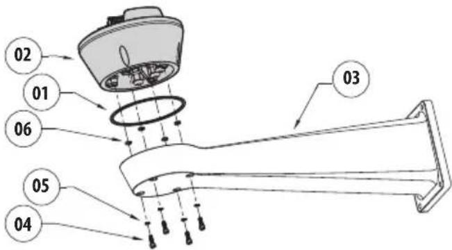
Fig. 11
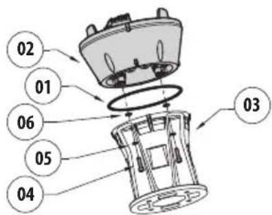
Fig. 12
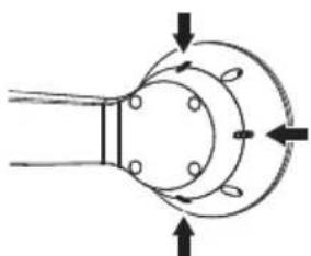
Align the 3 notches on the base with those on the support as shown in the following figure.
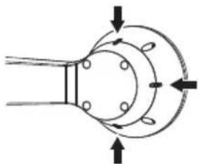

Fig. 13
Put some thread-locker into the holes for screws (Loctite 243).

Pay attention to the fixing. Tightening torque: 6Nm.
7.3 Connector board description
| CONNECTOR BOARD DESCRIPTION | |
| Connector/Component | Function |
| CN1 Power supply for the board | |
| CN4 Signal cables | |
| Ethernet Ethernet | |
| F1 Fuse | |
| F2 Fuse | |
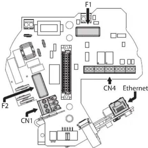
Tab.1
Fig. 14
7.4 Connection of the power supply line
Depending on the version, the device can be provided with different power supply voltages. The power supply voltage is indicated on the product identification label. (4.2 Product marking, page 8).

Electrical connections must be performed with the power supply disconnected and the circuit-breaker open.

When commencing installation make sure that the specifications for the power supply for the installation correspond with those required by the device.

Check that the power supply socket and cable are adequately dimensioned.

Earth cable should be about 10mm longer than the other two, so that it will not be disconnected accidentally if pulled.

The power supply cable must be covered by the silicone sheath (01) supplied. The silicone sheath must be fastened with the corresponding cable tie (02).
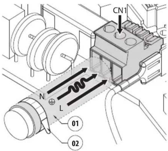
Fig. 15
7.4.1 24Vac power line connection
Cut the cables to the correct length and make the connections. Connect the power supply to the terminal: CN1.
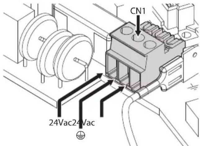
Fig. 16
Connect the power supply cables as described in the table below.
Tab. 2
| CONNECTION OF THE POWER SUPPLY LINE | |
| Colour Terminals | |
| Power supply 24Vac | |
| Defined by the installer 24Vac | |
| Defined by the installer 24Vac | |
| Yellow/Green | ◎ |
7.4.2 120Vac and 230Vac power line connection
Cut the cables to the correct length and make the connections. Connect the power supply to the terminal: CN1.
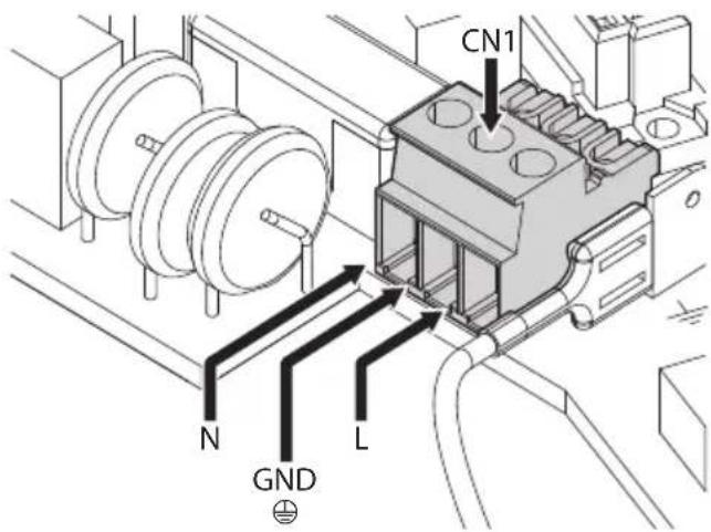
Fig. 17
Connect the power supply cables as described in the table below.
Tab. 3
| CONNECTION OF THE POWER SUPPLY LINE | |
| Colour Terminals | |
| Power supply 230Vac | |
| Blue N (Neutral) | |
| Brown L (Phase) | |
| Yellow/Green | ⊕ |
| Power supply 120Vac | |
| Blue N (Neutral) | |
| Brown L (Phase) | |
| Yellow/Green | ⊕ |
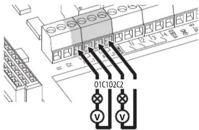
7.4.3 Connection of the alarm inputs, of the twilight switch and of the relays

CAUTION! TNV-1 installation type. The installation is type TNV-1, do not connect it to SELV circuits.

CAUTION! In order to reduce the risk of fire, only use UL Listed or CSA certified cables with sections greater than or equal to 0.14mm^2 (26AWG).
Standard version
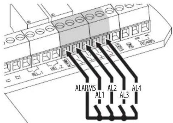
Fig. 18 Relay contact connection.
Fig. 19 Alarms connection.
Version with LED illuminators
Tab. 4
| CONNECTION OF THE ALARM INPUTS, OF THE TWILIGHT SWITCH AND OF THE RELAYS | |
| AL1, AL2, AL3, AL4 e ALARMS | Self-powered alarm inputs referring to the ALARMS common terminal |
| O1-C1 e O2-C2 | Clean output contacts, can be activated by alarm or by user control |

Connect the dusk switch to the ALARMS and AL1 terminals. AL1 is the default alarm contact for the light sensitive switch.
7.5 Connection of the Ethernet cable
Connect the ethernet cable to the relative connector (Ethernet, 7.3 Connector board description, page 13).
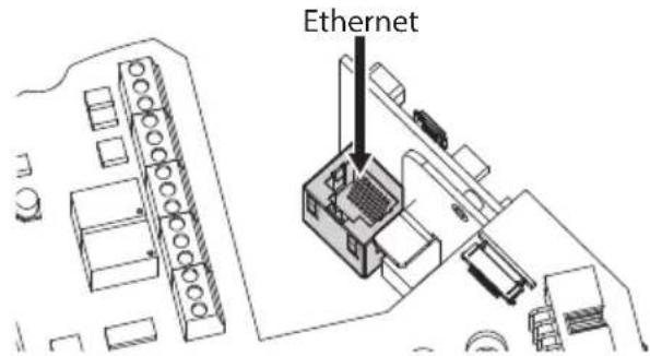
Fig. 20
7.6 Fixing the upper body
Fix the upper body (01) to the base (02) using the fixing screws (03) equipped with gaskets (04). Make sure the base seal is present and in good condition (05).

Pay attention to the fixing. Tightening torque: 4Nm.
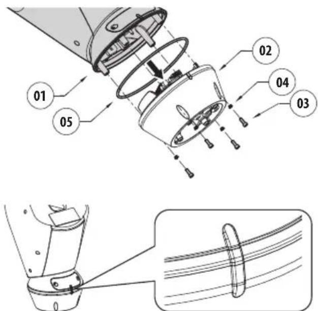

Fig. 21
There is one anchoring position between the base and upper body. Align side projections to obtain the correct positioning.
7.7 Counterweights installation
Fasten the counterweights to the housing using the screws and washers supplied.
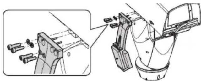
Fig. 22

Put some thread-locker into the holes for screws (Loctite 243).

Pay attention to the fixing. Tightening torque: 16Nm.
7.8 LED illuminators installation

To work properly both illuminators must be installed together.

From Pan & Tilt, it is only possible to install VIDEOTEC illuminators.
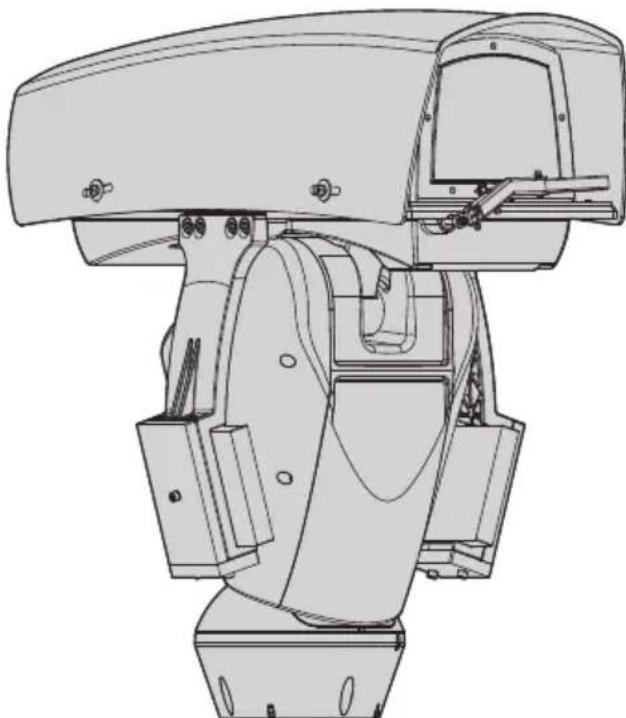
7.8.1 Counterweight removal
Undo the screws and remove the external counterweights.
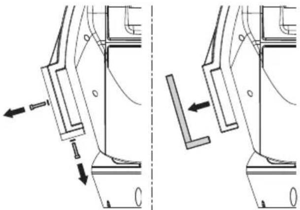
Fig. 23
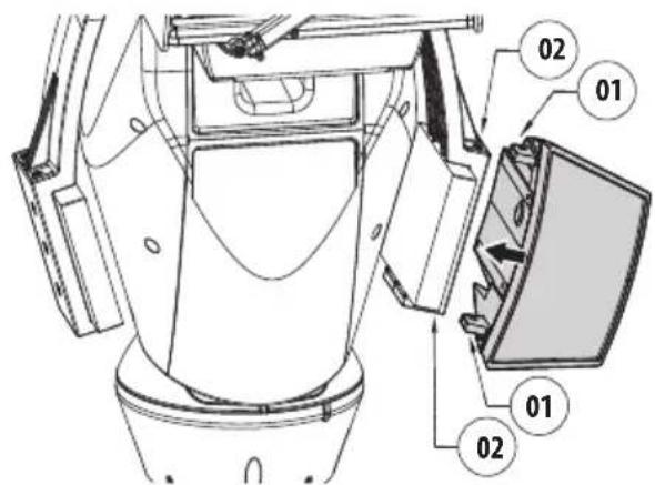
7.8.2 Fitting the illuminator on the bracket
Identify the front holes on the counter-weight bracket.
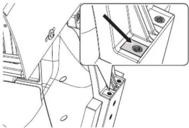
Fig. 24
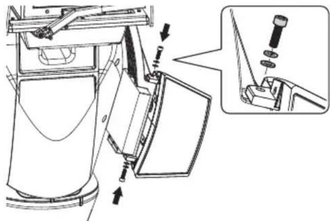
Place the fixings of the illuminator (01) on those of the bracket (02).

Fig. 25
Tighten the screws and the washers previously removed.


Fig. 26
Pay attention to the fixing. Tightening torque: 6Nm.
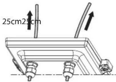
7.9 Connection of the LED illuminators
Insert the power supply cables through the cable glands by at least 25cm Tighten the cable glands.


Fig.27
To ensure the safety and the correct operation of the unit do not leave a surplus of the cable externally.
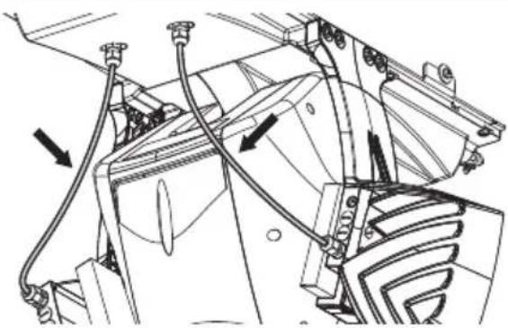
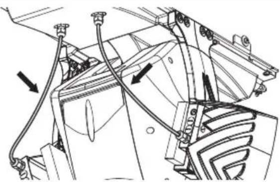
Fig. 28
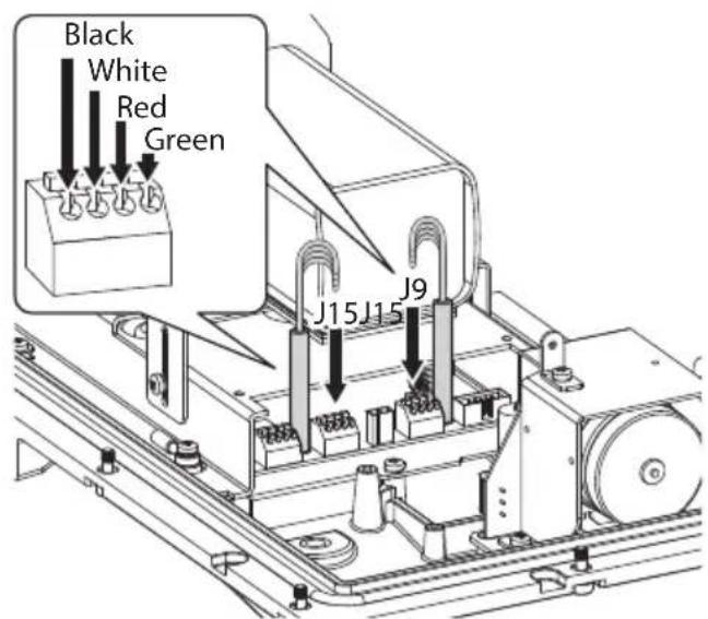
Connect the cables as shown in figure.
The left illuminator (MASTER) must be connected to connector J15. The right illuminator (SLAVE) must be connected to connector J9.

Fig. 29
7.10 LED illuminator activation and adjustment instructions
Once the adjustment is done the illuminator on the left (MASTER) synchronizes and controls the illuminator on the right (SLAVE).
The dusk switch detects the room light and controls the activation and deactivation of the illuminators when brightness reaches the level set by the user.
When the LED illuminators are active the camera goes to night mode with the special ONVIF control.
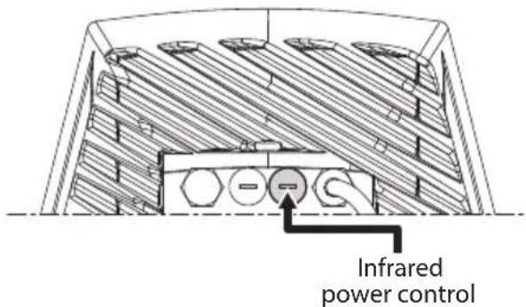
7.10.1 Description of the LED illuminator

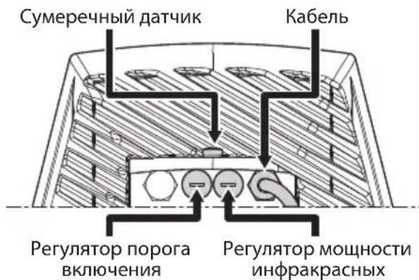
Do not remove the transparent screw of the twilight sensor in order not to affect the security and operation of the illuminator.
- Twilight sensor: Detects the light level.
- Cable: Power supply and control.
- Switch-on threshold regulator: The potentiometer allows adjusting the sensitivity threshold to switch on the illuminator.
- Infrared power control: The potentiometer allows adjusting the power of the illuminator.
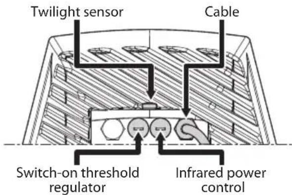
Fig. 30
7.10.2 LED illuminator switching on threshold adjustment

The illuminator on the right must always be set to maximum brightness.
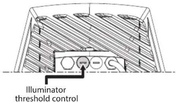
Fig. 31
The illuminator has an integrated twilight sensor that allows its automatic activation and deactivation at predefined luminous conditions.
The twilight sensor is set in the factory at a predetermined luminous level, suitable for most installations (approximately 50lx). If you want to adjust in different ways the threshold, loosen the plug on the illuminator rear and proceed for the adjustment with a screwdriver.
By rotating the trimmer clockwise, the night mode changeover is anticipated (at a greater luminous value). By rotating the trimmer anti-clockwise, the night mode changeover is delayed (at a lower luminous value).
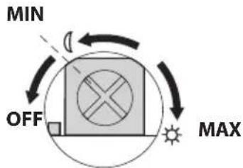
Fig. 32
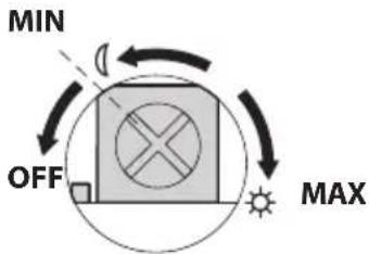
Wait for appropriate brightness before switching on the illuminator. Rotate the trimmer slowly until the LED on the side of the trimmer switches on. Once the intervention threshold has been surpassed (LED on), rotate it slightly in the opposite direction.

After making the adjustments make sure that the plug is closed tight to ensure perfect sealing.
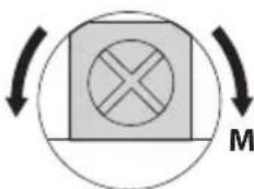
7.10.3 LED illuminator power adjustment

The illuminator on the right must always be set to minimum power.
The illuminator is set in the factory to provide maximum power. If you don't need to illuminate distant subjects or if the image is over-exposed for excessive brightness, decrease the power, so that energy saving is also obtained.
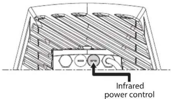
Fig. 33
Loosen the hermetic plug. Rotate the trimmer, clockwise to increase the power of the infrared illuminators and anti-clockwise to decrease it.
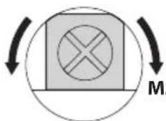
MAX POWERMIN POWER

Fig. 34
After making the adjustments make sure that the plug is closed tight to ensure perfect sealing.
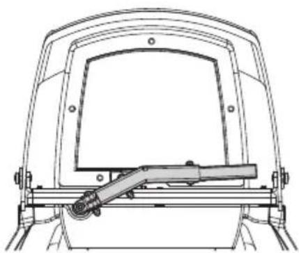
7.11 Fastening of the wiper blade
Insert the blade on the wiper shaft. Position the blade in the stop position.
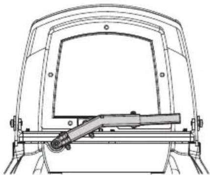
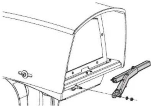
Fig.35 Fasten the whole assembly by means of the washer and nut.
Fig.36 The correct adjustment must allow the return of the blade to the stop position going to the end stop on the casing's plate.
8 Switching on

Ensure the unit and the other components of the system are appropriately closed to prevent contact with live parts.

During normal operation the surface of the illuminator can reach high temperatures. Do not allow direct contact and position the appliance where it is inaccessible to unauthorised persons. Before touching switch off the illuminator and allow to cool for a minimum period of 10 minutes.

Do not stay in the vicinity of the device when it is powered. Act on the device only in the absence of a power supply.

Make sure that all parts are fastened down firmly and safely.
The unit is switched on by connecting the power supply.
To switch off the unit disconnect the power.
9 Configuration
9.1 Web interface

The unit is configured to obtain an IP address from a DHCP server.

Browsers supported (the latest version): Microsoft Edge, Google Chrome™, Mozilla Firefox.

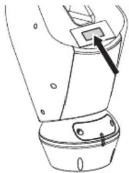
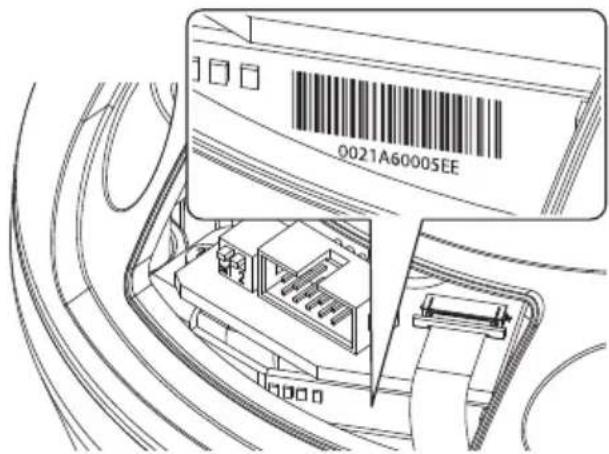
The MAC Address is contained on the label that is on the CPU board.
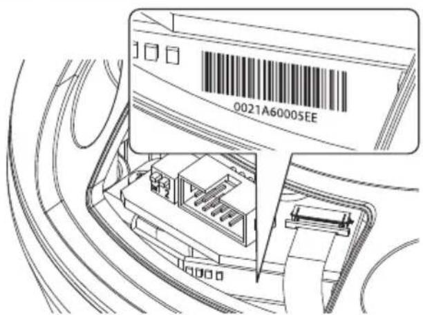
Fig. 37
The first operation in configuring the device consists in connecting to the web interface.
The IP address acquired via DHCP is visible in the DHCP server log file.
If the DHCP server is not available, the unit automatically configures itself with a self-generated IP address in the 169.254.x.x/16 subnet. Configuring the IP address of the PC as belonging to the same subnet (example: IP address: 169.254.1.1, subnet mask: 255.255.0.0).
Use an ONVIF compliant VMS or a network sniffer to find the IP address of the device (IP scan utility).
To access the Pan & Tilt web interface, simply use a browser to connect to the address http://ip_address and log in to Pan & Tilt using the predefined credentials:
-Username:admin
- Password: admin
9.1.1 Home Page
The product control interface is displayed if login is successful.

Fig. 38
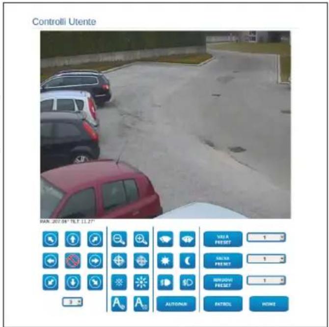
9.1.2 User Controls page
To control the device through the browser, select the User Control entry. A new window will open with a virtual keyboard to enter commands.
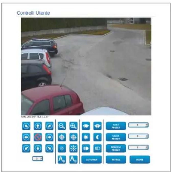
Fig. 39
The virtual keyboard contains the following controls:
- Speed selector: It selects the speed of the pan & tilt movements.

Fig. 40
- Zoom Wide/Zoom Tele


Fig. 41
Focus near/Focus far/Autofocus


Fig. 42
- Iris close/Iris open/Auto iris


Fig. 43
- Wiper/Washer


Fig. 44
- Day: Activate the camera's IR filter. If available, it turns off the LED illuminators.

Fig. 45
Night: Deactivate the camera's IR filter. If available, it turns on the LED illuminators.

Fig. 46
- Visible Cut Filter On: Enable the Visible Cut Filter (in models with this feature.). This filter allows for sharp images (black and white) under hazy conditions or backlit shots.

Fig. 47
Visible Cut Filter Off: Disable the Visible Cut Filter (in models with this feature.).

Fig. 48
- Autopan: Enables the cyclical positioning between 2 preset of pan, tilt and zoom.
AUTOPAN

Fig.49
- Scan Preset/Set Preset/Remove Preset
Fig. 50
- Patrol: Enables the automatic patrol mode repeating in sequence, or random, the presets of pan, tilt and zoom.

Fig. 51

- Back to Home
Fig. 52
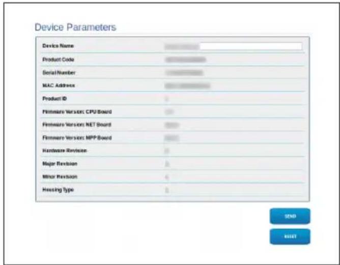
9.1.3 Device Parameters Page
From menu entry Device Parameters it is possible to set the name of the device and view other additional information.
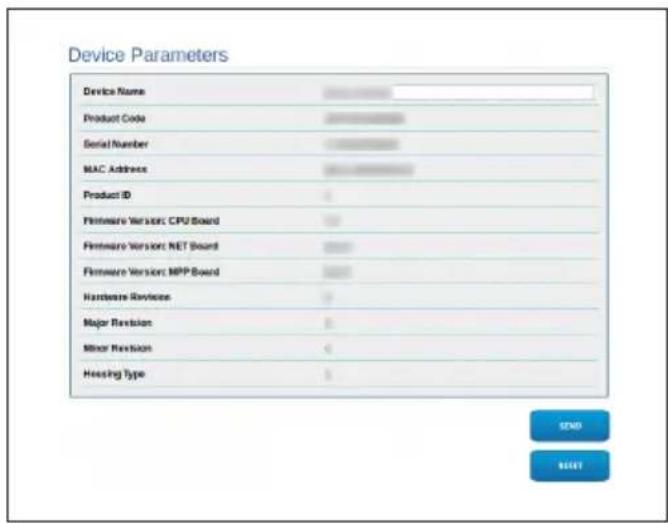
Fig. 53
9.1.4 Device Statistics Page
The Device Statistics menu outlines, for consultation only, all the statistics collected during device operation.
Device Statistics
| Pax degrees | 3354 |
| Ht degrees | 1442 |
| Power up | 133 |
| Working hour | 20 |
| Heating rate temperature (°C) | 40 |
| Heating rate temperature (°C) | 65454 |
| Pax load rate temperature (°C) | 90 |
| Pax load rate temperature (°C) | 22 |
| CPU load rate temperature (°C) | 43 |
| CPU load rate temperature (°C) | 20 |
| Net heat rate temperature (°C) | 20 |
| Net heat rate temperature (°C) | 15 |
| BLight Off hours | 0 |
9.1.5 Network Configuration page
From menu entry Network it is possible to change the setting of the Pan & Tilt network. It is possible to decide whether the device requires an address assigned statically, dynamically with DHCP or self-generated. The device supports the Internet Protocol (IP) in version 4.

Fig. 54
With self-generated address the device will automatically assign itself an address in the range 169.254.0.0/16.
From the same page it is possible to configure 2 DNS and decide which mechanisms must be enabled to automatically identify the devices in the local network.
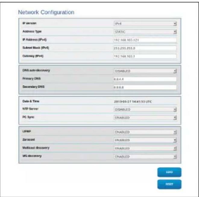
Fig. 55
NTP Server: It is also possible to specify if the device needs to be synchronised with an external NTP (Network Time Protocol) server.
- DISABLED: Select this option if you do not wish to synchronise date and time of the device.
- DHCP: Select this option if you wish to synchronise the date and time of the device with those of an NTP server (Network Time Protocol) indicated by the DHCP server.
- STATIC: Select this option if you want to synchronise the date and time of the device with those of the NTP server specified by the static address.

In order for the device to operate correctly, it is necessary to synchronise it with the VMS software using a NTP server.
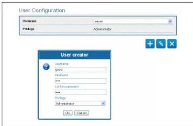
9.1.6 User Configuration page
From menu entry User Configuration it is possible to manage all users that have access to the device. Administrator type users can access the complete configuration of the device. Users such as Operators, Users and Anonymous have limited access to the management pages.


Fig. 56
The device can be configured only by users with administration privileges.
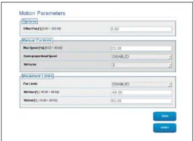
9.1.7 Motion Parameters Page
From menu entry Movement Parameters it is possible to control, via web, all Pan & Tilt parameters.
- Offset Pan: The pan & tilt has a mechanically defined 0^ position. The Offset Pan function allows the definition of a different 0^ position using software.
Maximum Speed: Sets the maximum manual speed. - Speed with Zoom: When enabled, this parameter automatically slows down the Pan & Tilt speed, based on the Zoom factor.
- Tilt Factor: Sets the reduction factor of the tilt axis manual speed.
- Pan Limits: Enables the limits of Pan.
- Pan Start: Sets the start limit of Pan.
- Pan End: Sets the end limit of Pan.
- Tilt Start: Sets the start limit of Tilt.
- Tilt End: Sets the end limit of Tilt.
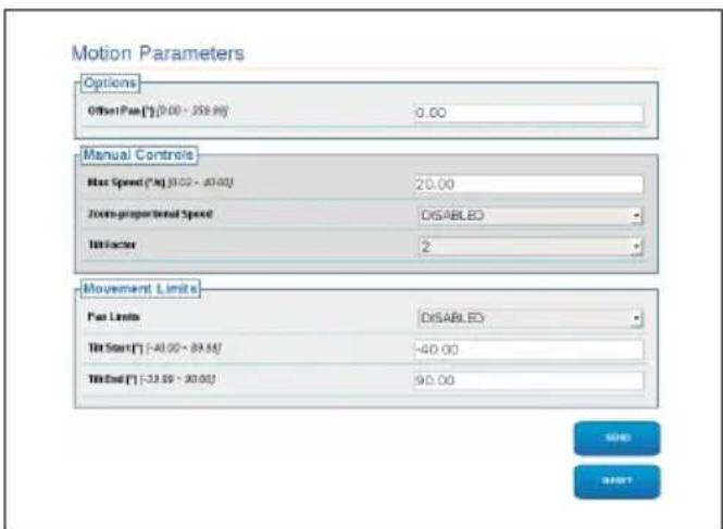
Fig. 57
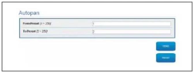
9.1.7.1 Autopan Page
From menu entry Autopan it is possible to specify the preset autopan start and end.
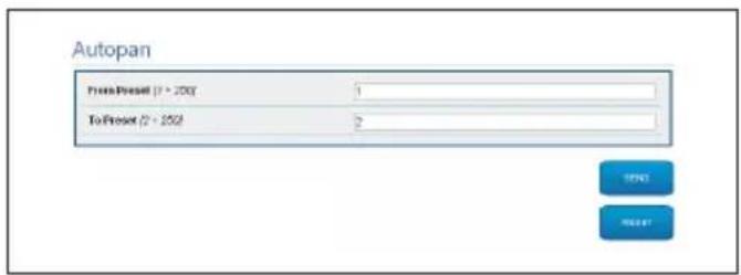
Fig. 58
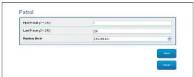
9.1.7.2 Patrol Page
From menu entry Patrol it is possible to specify the preset patrol start and end. It is possible to specify whether the scan of the presets needs to be carried out randomly or otherwise.
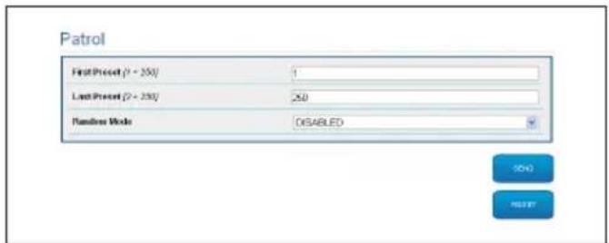
Fig.59
9.1.7.3 Motions Recall Page
From menu entry Motion Recall it is possible to specify a time interval of inactivity after which Pan & Tilt will carry out one of the following functions: return to Home position, start autopan or start patrol.
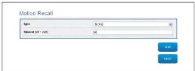
Fig. 60
9.1.8 Preset Parameters page
From menu entry Preset Parameters a number of parameters relative to the presets can be configured:
- Scan Speed: The speed, measured in degrees to the second, at which a preset is reached by explicit operator request.
Ramp type: This allows you to select the Pan & Tilt accelerations. - Speed of Movements Default: The speed used in autopan and patrol operations.
- Impose Default Speed: The default speed will also be set as the scanning speed for all presets.
- Default Dwell Time: The amount of time, in seconds, it stays in each preset by default.
- Impose Default Pause: The default pause will be set for all presets.
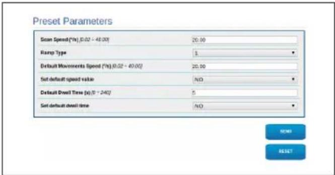
Fig. 61
9.1.9 Preset Parameters page (Advanced)
In the Preset Parameters (Advanced) section it is possible to customise the speed and pause values for each preset, in addition to enabling/disabling the presets themselves.
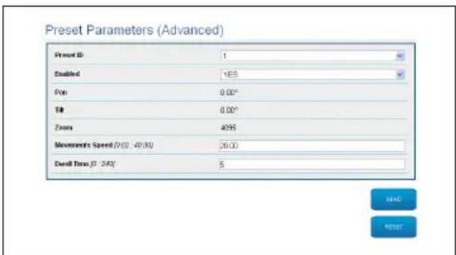
Fig. 62
9.1.10 Digital I/O Page
From menu entry Digital I/O it is possible to configure the digital channels available in the device. What follows is a brief description of the configurable parameters for each digital input.
- Alarm ID: Field used to select the desired digital input.
- Type: It indicates the default state of the digital input.
-
Action: Each input can be associated with an action. The action is activated when the contact is in a state other than default. The available actions are listed below:
-
NONE: No action.
- SCAN: Position the pan & tilt on the selected preset.
PATROL: Activate the PATROL.
AUTOPAN:Activate AUTOPAN. - WIPER: Activate the Wiper.
- WASHER: Activate the glass cleaning sequence.
- RELAY 1: Activate Relay 1.
- RELAY 2: Activate Relay 2.
- IR FILT: Deactivate the camera's IR Filter. If available, it turns on the LED illuminators.
To check correct operation of the alarms, a dot will appear on the web page. The dot will be green in normal conditions and red when an alarm is detected.
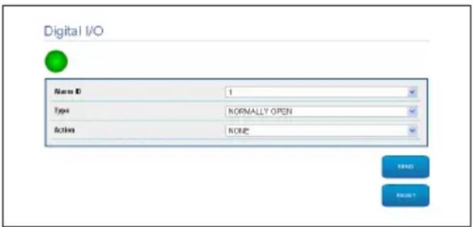
Fig. 63
9.1.11 Washer page
From the Wash system menu, it is possible to configure the device wash system functions.
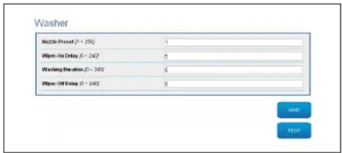
Fig. 64
9.1.12 Camera Settings page

The change in data in the "Protocol and authentication" section could make the camera inaccessible. The data set by default allow correct access to the system.

You are advised not to change the data in the "Lenses Features" section to avoid prejudicing correct system operation. The only useful field for the end user is "Autofocus".
This section displays the data for the different ONVIF profiles exported from the camera.
Camera Settings
| Protocol and Authentication | |
| Protocol | ON/F PROFILES |
| Username | service |
| Password | *** |
| Confirm password | *** |
| Streaming Profiles | |
| Profile ID | 0 |
| Profile | media_profile1 |
| Code | H264 |
| Resolution | 1020 x 1080 |
| Frame rate limit | 30 fps |
| Edge rate limit | 5000fps |
| GOP | 30 frames |
| Zoom enabled | No |
| Lenses Features | |
| Lens | MOTORIZED |
| Zoom ratio/(°*°) | 1 |
| Lens positioning range (°*°) | 20 |
| Motor Type | INVERTED POLARITY |
| Rotation polarity of the lens Zoom | POSITIVE |
| Rotation polarity of the lens Focus | POSITIVE |
| Rotation polarity of the lens Intra | POSITIVE |
| IR Probe | EXTERNAL |
| Autofocus | MANUAL TRIGER ONLY |

Fig. 65
To edit the camera settings, select the VTTunnel button or simply the Camera button in the tools menu (9.1.13 Tools Page, page 28).
9.1.13 Tools Page

If resetting, the PTZ is restored to default conditions. To access the system, following the instructions in the relevant chapter (9.1 Web interface, page 21).
From menu entry Tools it is possible to re-set the predefined values for the entire configuration of device or only for a number of specific sections.
This section:
- Update the firmware of the device.
- Restart the device.
- Download the VTTunnel application to enable the connection with the IP camera needed to access its web page. (9.2 VTTunnel, page 30).
- Open the web pages of the camera (9.3 Camera, page 30).
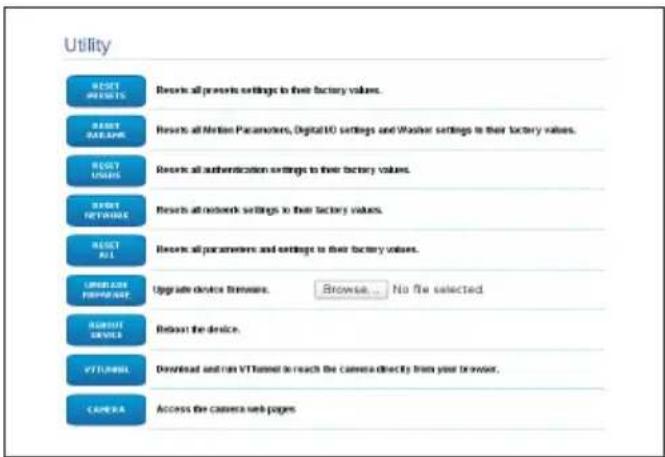
Fig. 66
9.1.14 Factory Default

If the access password to Pan & Tilt is no longer available, follow the procedure to reset to default settings using the Reset key, situated inside the product.

To search and identify the Pan & Tilt, following the instructions in the relevant chapter (9.1 Web interface, page 21). In this case however, the access credentials to the system are those of the camera and not Pan & Tilt. If the credentials are those of camera default (set by Videotec) they are:
Login: service
Password: Videotec2020-
To restore the factory settings relative to the network, user access and camera configuration follow this procedure:
Power the unit.
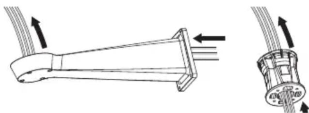
- Open the cover of the DIP-switches.
- Detect DIP switch 4 (01). Bring switch 1 down, 1 (ON) value.
- Wait for the temporary shutdown of the LEDs (02).
- Bring switch 1 up, 0 (OFF) value.
- Close the connector housing cover.
- Follow the instructions in paragraph 9.1 to search the address (9.1 Web interface, page 21).
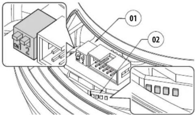
Fig. 67
The required parameters are:
The IP protocol used to communicate with the camera (ONVIF PROFILE S).
- The type of lens installed (MOTORISED).
- The credentials necessary for connection to the IP camera (username: "service"; password: "Videtotec2020").
- Restart the device.
- If still set in DHCP, the product could have changed address.
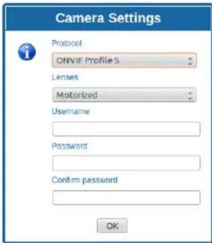
Fig. 68
9.2 VTTunnel

The application works only with Java™. If Java™ is not installed download the latest version at www.java.com.

The application can be connected only to the first interface of the network. Leave only the network cable connected to the pan & tilt.

The execution of the application requires computer administrator privileges. The following message may appear on the screen: You have to execute Javaw as administrator. In this case the execution properties of the file in the Java installation folder must be modified.
In order to connect the web camera you must use the program VTTunnel, available in the Tools menu.
When the program starts, a list of networked devices will be shown. To connect to the camera select the pan & tilt desired and press the Connect key.
Once the connection is established, the web page of the IP camera can be reached at 192.0.0.64.
When the operations on the camera are done, you can close the connection by clicking the Disconnect key. It is possible to connect to one camera at a time, so you need to disconnect from the P&T unit before operating on a different unit.
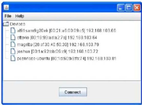

Fig. 69
Restart the Pan & Tilt if video streaming parameters have been modified during the configuration of the camera.
9.3 Camera

For detailed information, refer to the camera manual, which can be downloaded from the web.

To access the camera menu, Pan & Tilt must not have an auto-generated address or in DHCP.
Access the camera web page.
The default data to access the camera are:
- Login: "service"
- Password: "Videotec2020"
10 Accessories

For further details on configuration and use, refer to the relative manual.
10.1 Washer
The product can be equipped with an external pump that provides water to clean the glass.
When a control is provided, the Pan & Tilt is positioned with the window in front of the nozzle. (9.1.2 User Controls page, page 22). The pump and wiper are activated for a set period of time. At the end of the operation the P&T returns to its initial position.
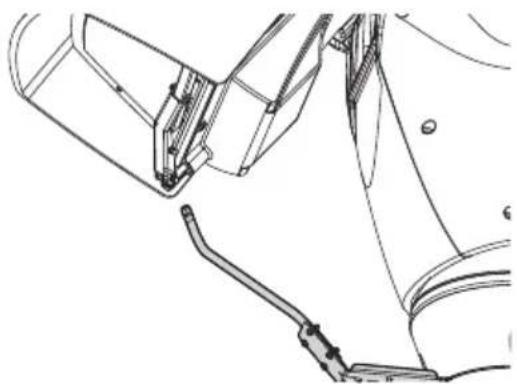
Fig. 70
10.1.1 Washing system connection

CAUTION! TNV-1 installation type. The installation is type TNV-1, do not connect it to SELV circuits.

CAUTION! In order to reduce the risk of fire, only use UL Listed or CSA certified cables with sections greater than or equal to 0.14mm^2 (26AWG).

All signal cables must be grouped together by means of a cable tie.
| WASHING SYSTEM CONNECTION | |
| Terminals Description | |
| O1-C1 Clean contact to activate the washing system. | |
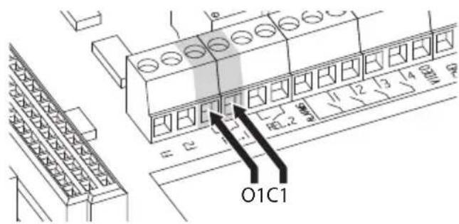
Tab. 5
Fig. 71
10.2 Wall mount bracket
Wall bracket with internal cable channel.
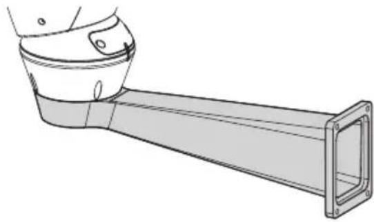
Fig. 72
10.3 Parapet bracket
Parapet bracket with internal cable channel.
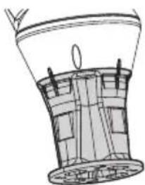
Fig. 73
10.4 Power supply with illuminator control
Weather-proof box with power supply and control of the illuminators.
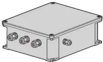
Fig. 74 Version of the standard box.
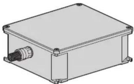

Fig. 75 Version of the UL certified box.
For further information refer to the relative chapter (7.4.3 Connection of the alarm inputs, of the twilight switch and of the relays, page 15).
11 Maintenance

CAUTION! Device installation and maintaining must be performed by specialist technical staff only.

Maintenance must be carried out by personnel trained to operate on electrical circuits.
11.1 Fuses replacement

Maintenance must be performed with the power supply disconnected and the circuit-breaker open.
If necessary, replace the fuse illustrated in figure (7.3 Connector board description, page 13).
Tab. 6
| FUSES REPLACEMENT | ||
| Voltage Fuse F1 Fuse | F2 | |
| 24Vac, 50/60Hz F 6.3A | H 250V 5x20 T 8A H 250V 5x20 | |
| 120Vac, 50/60Hz F 6.3A | H 250V 5x20 T 4A H 250V 5x20 | |
| 230Vac, 50/60Hz F 6.3A | H 250V 5x20 T 2A H 250V 5x20 | |
12 Cleaning
12.1 Cleaning the window and plastic parts

Avoid ethyl alcohol, solvents, hydrogenated hydrocarbide, strong acid and alkali. Such products may irreparably damage the surface.
We recommend using a soft cloth with neutral soap diluted with water or specific products to clean the glasses lenses.
13 Information on disposal and recycling
The European Directive 2012/19/EU on Waste Electrical and Electronic Equipment (WEEE) mandates that these devices should not be disposed of in the normal flow of municipal solid waste, but they should be collected separately in order to optimize the recovery stream and recycling of the materials that they contain and to reduce the impact on human health and the environment due to the presence of potentially hazardous substances.

The symbol of the crossed out bin is marked on all products to remember this.
The waste may be delivered to appropriate collection centers, or may be delivered free of charge to the distributor where you purchased the equipment at the time of purchase of a new equivalent or without obligation to a new purchase for equipment with size smaller than 25cm (9.8in).
For more information on proper disposal of these devices, you can contact the responsible public service.
14 Troubleshooting

Contact an authorized support centre if the problems listed below persist or you have any other issues that are not described here.
PROBLEM The product does not go on.
CAUSE Wiring error, blown fuse.
SOLUTION Make sure the connections are correct. Check the continuity of the fuses and replace them with the indicated models should they fail.
PROBLEM During start-up the pan & tilt is disabled.
CAUSE Ambient temperature is very low.
SOLUTION Wait until the end of the preheating procedure.
PROBLEM The camera is not focusing correctly
CAUSE The camera has lost settings
SOLUTION Contact support for the guided back focus procedure.
PROBLEM At low temperatures, video streaming cannot be reached, many items on the menu are disabled.
CAUSE The system is still in the de-icing phase (typically lasts 1 to 2 hours)
SOLUTION From the tools menu, click the START button. If the ambient temperature is too low the unit will remain blocked.
15 Technical data
15.1 General
Top mount (OTT)
Transmission through toothed belt
Slip-ring
Electronic limit switches
Zero backlash
Optical sensors for absolute positioning feedback
Integrated wiper
Pre-installed camera and lens
15.2 Mechanical
Constructed from aluminium and tecnopolymer
Epoxypolyester powder painting, RAL9002 colour
Horizontal rotation: 360^ , continuous rotation
Zoom 33x:
Vertical rotation: from -20^ up to +45^
Horizontal speed (variable): from 0.02^ / s up to 20^ / s
- Tilt speed (variable): from 0.02^ / s up to 20^ / s
Accuracy of preset positions: 0.02^
Cable glands: 3xM16
Unit weight: 30kg (66lb)
15.3 Electrical
Supply voltage/Current consumption:
230Vac, 0.4A, 50/60Hz
120Vac, 0.8A, 50/60Hz
24Vac, 4A (8A with LED illuminators), 50/60Hz
Power consumption (illuminators off):
24W, P&T static (stand-by), heating switched off
100W, P&T in motion, heating switched on
Power consumption (illuminators on):
150W, P&T in motion, heating switched on, illuminators to minimum power
190W, P&T in motion, heating switched on, illuminators to maximum power
4 self-powered alarm inputs
2 dry contacts: 30Vdc max or 30Vac, @ 1A
15.4 Communications
Connector: RJ45, 10BASE-T/100BASE-T
Protocol: ONVIF, Profile S (TCP/IPv4, UDP/IPv4, HTTP, NTP, DHCP, WS-DISCOVERY, QoS, RTSP, RTCP, RTP)
15.5 Cameras
Day/Night Full HD, 60fps, sensor CMOS 1/2.8"
Effective Pixels: 2 Megapixel
Minimum Illumination, color (ICR-OFF):
0.041lx1/25sF3.0,50IRE
Minimum Illumination, B/W (ICR-ON):
0.005lx1/25sF3.0,50IRE
Zoom 33x:
Horizontal Viewing Angle: from 20.51^ (wide end) up to 0.65^ (tele end)
Vertical Viewing Angle: from 11.58^ (wide end) up to 0.36^ (tele end)
S/N Ratio: over 55 dB
HDR mode: 110 dB WDR (Measured according to IEC 62676 Part 5)
Adjustable picture settings: Contrast, saturation, Brightness
White balance: from 2500K up to 10000K, 4 automatic modes (base, standard, sodium lamp, dominant color), Manual mode and Hold mode
ALC level: Adjustable
Saturation: Adjustable from peak to average
Shutter: Automatic Electronic Shutter (AES, Automatic Electronic Shutter); Fixed shutter (from 1/25 [30] up to 1/15000)selectable; Default shutter
Day/Night: Auto (adjustable switch points), color, monochrome
Sharpness: Sharpness enhancement level selectable
Contre-jour compensation: On/Off/Intelligent Auto Exposure (IAE)
Contrast optimisation: On/Off
Disturbance reduction: Intelligent Dynamic Noise Reduction with separate temporal and spacial adjustments
Intelligent Defog
Video Content Analysis Intelligent Video Analytics
Scene mode: 10 default modes with planner: Indoor, Outdoor, Traffic, Poor lighting, Intelligent AE, Vibration, Low bitrate, Sport and play, Shops, Plate recognition (LPR)
Zone darkening
15.6 Lenses
Zoom 33x 15.2-500mm (0.6-19.7in), F3.0 (Thermal compensation system and Visible Cut Filter)
15.7 Environment
For indoors and outdoors installation
Operating temperature
- Continuous working: from -40^ (-40^) up to +60^ (140^)
Non continuous working (absolute maximum temperature for short periods): +65^ (149^)
Cold start (33x lenses): -30^ (-22^)
Surge immunity: up to 2kV line to line, up to 4kV line to earth (Class 4)
Relative humidity: from 10% up to 95% (no condensation)
15.8 Certifications
Electrical safety (CE): EN60950-1, IEC60950-1, EN62368-1, IEC62368-1
Electromagnetic compatibility (CE): EN50130-4, EN61000-6-4, EN55022 (Class A), FCC Part 15 (Class A)
Outdoor installation (CE): EN60950-22, IEC60950-22
Photobiological safety (CE): EN62471 (LED illuminators)
IP protection degree: EN60529, IP66
Salty fog resistance: EN50130-5, EN60068-2-52
EAC certification
NDAA compliant
16 Technical drawings

The indicated measurements are expressed in millimetres.

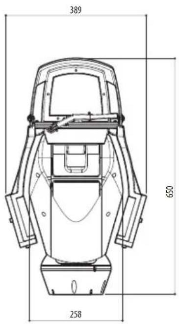
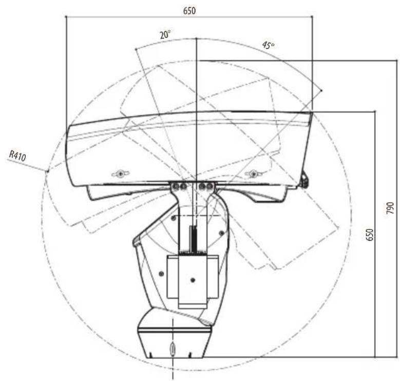
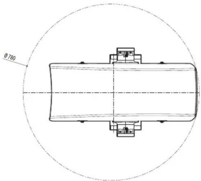
Fig. 76 ULISSE RADICAL, Zoom 33x.
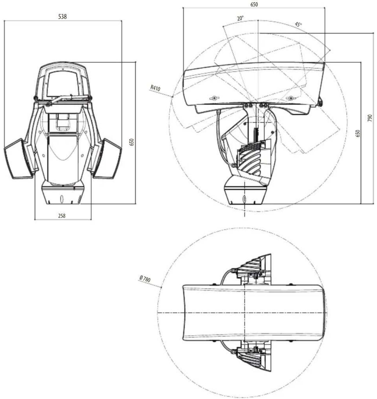
Fig. 77 ULISSE RADICAL, Zoom 33x , version pre-arranged for the installation of two LED illuminators.
ULISSE RADICAL
Hazardous moving parts. Keep fingers and other body parts away.
AVERTISSEMENT!
-Username:admin
- Password: admin
9.1.1 Pagina Home
Focus near/Focus far/Abstract


Fig.42
- Iris close/Iris open/Auto iris


Fig. 43
- Wiper/Washer


Fig. 44
- Login: "service"
- Password: "Videotec2020"
10 Accessori

Day/Night Full HD, 60fps, sensore CMOS 1/2.8"
Illuminatione Minima, B/W (ICR-ON):
0.005lx1/25sF3.0,50IRE
Zoom 33x:
Hazardous moving parts. Keep fingers and other body parts away.
AVERTISSEMENT!
Focus near/Focus far/Autofocus


Fig. 42
- Iris close/Iris open/Auto iris


Fig. 43
- Wiper/Washer


Fig. 44
10.2 Support fixation murale
10.3 Support fixation sol
Rotation horizontal: 360^ , rotation continue
Zoom 33x:
Hazardous moving parts. Keep fingers and other body parts away.
AVERTISSEMENT!
- Focus near/Focus far/.Autofocus


Abb.42
- Iris close/Iris open/Auto iris


Abb.43
- Wiper/Washer


Abb.44
m = 311
Abb.53
Day/Night Full HD, 60fps, sensor CMOS 1/2.8"
Effective Pixel: 2 Megapixel
Danhao onepaunKpainheBaXHa
dЯобсесунnaнkaшero
fYHKUHOHPOBaHHcNCTeMbI.BHMaTeNbHO
O3HaKoMbTecb COnncaHem npoceDpybl
BbINHHTe ee B COOTBeTCTBUN C npNBedeHHbIMN yKa3aHnA M.

INFO
Onncahne xapaktepncnK cnTeMbI.
PekomeHnyem BHIMaTeIbHO 03HaKOMITbCc cOedepeXaHHeM 3TORo pa3dena,ДЯ TORO uTo6bl NOHrTb CneDyUoUne 3Tanbl.
2 Птумейня В OTHOSEHn ABTOPCKOtro празви Инфорmaцnia O TOPROBbIX Маркax
Ha3BaHnY yCTPOIcTB nJI NKmHaHn, yNOMnHaEmbIE B HaCTOaIeM IOKyMeHTe, YBIAOTcT OTOBbIMN MapKaMn IINI 3apeRNTcPnpOBaHHbIMN TOPROBbIMN 3HaKaMn COOTBeTcTBYIOUX KOMNaHn.
ToprobamapkaONVIFnpnHaJIeKHTOnvif,Inc.
3 ПравILA Тхнки 6e3oNaCHOCTN

IPEDUYPEXKDEHNE! CnCTema 3neKTPoNTaHn, K KOtopoN IODKnIOucaETcY UCTPOINCTBO, DOnJXHa MMeTb ABTOMATNUeCKN DBYXNOIIOCHbI BbIKIOUaTeNb cenn 20A max. 3TOT BbIKIOUaTeNb BbIbnpaETcN 3 nepeuNCHeHHbIX B cInCKe. MinHMaJIbHOe pacCTOraHnE MeKdy KOHTaTMn ABTOMATNUeCKORO BbIKIOUaTeNr cenn dONJHo COCTABnAYTb 3mm. BbIKIOUaTeNb cenn dONJxEN HMMeTb 3auNTy OT TOKa K3 Ha 3emNI (dNΦepeHuaJIbHna 3auNTa) n 3auNTy OT neperpy3kn no ToKy (tePMomarHnTHa 3auNTa).

IPEdYIPPEXDEHNE!OnaChbIe DnKyuuecraTeaTm, CneIte 3a Tem, UTo6bl NaBcuI N pyrue qactu Tena 6bln Ha 6e3onacHom pacctoHnn.

IPEdUYPEXKDEHNE!YcTaHOBka mO6cnyXnBaHne yCTpOoiCTBa DOJIKNbIOCUyIeCTBJIrTbCra TOnbKO cNeuaJIaN3uPObaHHbIM NepcoHaIOM.

PNEyPEXKDEHNE! Dna o6ecneueHnnoCToHHo3aunTbI OT pncKa BO3ropaHn npu 3aMeHe npedoxpAHNTe ne dyetNCNoJb3OBaTb npedoxpAHNTe nTOrO Je TnPa N HomHaHa.Tolbko 06cnykBaIOUm nepcoHaN moKeT npobODntb 3aMeHy npedoxpAHNTe.

IPEyIPEXJEHNE! CnCTema Tnna HTC-1 3To CnCTema Tnna HTC-1, He nodknoaute ee K CHbH-cxemam.

PNEyPEXKDEHNE!IЯ cHxKeHn pNcKa BO3HnKHOBeHn NOxapa NcNoJb3yInTe NCKIOHTeBn Ka6enn UL nn CSA, ceyeHne KOToPbIX npeBbIaet nn paBHo 0,14mm² (26AWG).
-ПюИЗВОДNTeь He HeCet OTBETCTBEHNOCTn 3a ЛIO6bIe NOBpeXJdeHnY, BO3HnKaIOUne B pe3yJIbTaTe HeINpaBnJIbHOro INcNoJIb3OBAHnY yKa3aHHOrO B HaCTOaIeM pyKOBODCTBe O6OpyIDoBaHnY. ПOMmO 3TOrO, pON3BODITeNb COxpaHReT 3a co6oI npaBO n3MeHЯTb COdepXaHne pyKOBODCTBa 6e3 прEdBaPteIeHoro yBeIOMNeHnY. ПpeIcTAbIeHnA B HaCTOaIeM pyKOBODCTBe DOKymEHTaUng IpoWla tIaTeJIbHyIO npOBepKy. Ondako пюИЗВОДNTeN He HeCet OTBETCTBEHNOCTn 3a ee INcNoJIb3OBAHnE. Анlorичые YcIOBnIpydycMOtpeHbI B OTHOWeHn IIO6Oro NIIuA uN KOMPaHnN, npINBLeueHbIX dIЯ CoCTaBleHnI N Co3DAHnI DAHHORO pyKOBODCTBa.
-Перед Tem,кaknpuctyntb KBbINOLHeHIO IIO6bIX Opepaun, y6eINTecb B TOM,чTO INCTOCHNK NITaHnYcTPOINCTBa OTKIIQUeH.
He nCnoB3yIte Ka6eI, KOtOpbIe KaKcyTcN 3HOWeHHbIMN IIN CTapbIMN.
HnKoIgda n Hn npKaKnx 06CTOaTeNbCTBax He BblIOJIHrIe n3MeHeHn nnnoKlUoyen, He npEydCMOTpeHHbIX HaCTOaIIM pyKOBoDCTBOM. HeHaJNeXaUee nCNoIb3ObaHne o6OpyDoBaHn MOKeT npVBecTN K Bo3HnKHOBeHNIO cepbe3HbIX ONaChbIX CNTyaU, yrpoXaUOux 6e3OnaNacHOCTn nepcoHaJa n CnCTembl.
IcnoJb3yTe TObKO OpunHaJIbHbIe 3aNaChbIe qactn. HeopunHaJIbHbIe 3aNaChbIe qactn MOryt npNBecTn K BO3HKnHOBeHIO NOXapa, 3JeKtpnueCKO ra3pRJa nn dpyroJ onaCHO cnTyauuN.
- Пец монтамхом поверпс соотьетчье
нocтаблесьх MaTeрnaJOB сециФИКациям
Зakazа, Севпв ИдентиФИКAUОнье ярльк (4.2.
Mapknipobka Издени,старниа 8).
Kateropn yctaHOBKn (taKke Ha3bBAeMa KaTepnei nepeHapJxKeHn) yKa3bBaet Ha ypoBeHb CeTeBbIX cKaUKB HApJxKeHn, KOToPbIM noDBepKeHo o6OpyDobAHne. Kateropn 3aBcNt OT MeCTa pa3MeueHn OBOpyDobAHn IHaJIuHn KaKnx-JIbO yCTPOINCTB 3aunTbI OT cKaUKB HApJxKeHn. O6OpyDobAHne, YCTaHaBnBaemoe Ha npOMblIeHNHom 6bEKeT E HApPMyIO NOkJIouAeMoe K MaINCTpaJIbHbIM IINHM CETN PNTAHN,OT HOcNtC K KaTepOpn UCTaHOBKn III. B 3Tom Clyuae Heo6XODIMO CHN3ITb KateropnIO nepeHapJxKeHn DO II. 3TOrO MoXHO Do6ntbc NytEm NCNoB3OBaHn I3OJIpyUoZero TpaHCΦOpMaTopa C 3a3eMLeHHbIM 3KpaHOM MExdy NepBNUHO IN BTOpNUHO NBMOtKO INI PyTEM UCTaHOBKn yCTPOINCTB 3aUNTbI OT cKaUKB HApJxKeHn (Y3CH), UL listed, Ha yUacTKe MExdy faoH n Hylm, a TaKxe Hylm IN 3eMNe. CepTNΦNUPOBaHhble yCTPOINCTBa 3aUnTbI OT cKaUKB HApJxKeHn IDONKhbl ObecneuBaTB MHorOKpTaHoe ORpaHueHne cKaUKB HApJxKeHn IN IOXoDNtB dIn PA60tB I B CledyUoX HOMHaNbHbIX yCNOBHX: TIn 2 (Y3CH, NoCToRHHo NOkJIouEHhble K CETN PNTAHN IN IpeDaHa3NaueHhble dIn yCTaHOBKn HA CTOpOHe Harpy3KN BCNOMORAteNBHO O6OpyDobAHn); HOMHaNbHbI TOK p3Pra (In) mIn. 20kA. Hanprimep, moKho nCnoJIb3ObaTb:FERRAZ SHAWMUT, STT2240SPG-CN, STT2BL240SPG-CN c HomHaIom 120Vac/240Vac, (In=20kA). MakcImaIbHoe pacCToRAnHe meKdy uCTPOINCTBOM IN orpaHnHTeLem nepeHapJxKeHn COCTABLAE T5m.
- 3TO yCTPOIcTBo pa3pa6OtaHO IJIa NOKJIIOueHnIy UCTAHOBKn Ha 3daHnn NII INoXoJaIeKOHCTpykCnHa NoCToARHOI OCHOb. YCTPOIcTBO CNeDyeT HAdEJxHO 3aKpeNtB I NOKJIIOUHTb NepeB BblONHeHm KaKx-JIn6o pa6Ot.
- Θл ektpи ueckay cntema OCHaцаetcBbIKIIOUaTeJIeM PNTaHnA, KOTOpbIM MOxHO JERKOnHaHTN IN CNOJIb3OBAtB CnUyae Heo6XODIMOCtN.
- OTdJIbHnA 3aUHTHa 3a3EmJIOUaKNeEMMa yCTPOINCTBa DOJXHa 6bITb NOCTOHNHO NOKIIOUeHa K npoBODy 3a3EmHeHH.
-ПОДКЛIOUHTe yCTPOIcTB K NCTOUYKny NITAHNBA COOTBeTCTBUN C yKa3aHnMn Ha 3TNKeTke CMapKnIpOBkoJ. Ipeep Tem Ka NpOdoJIxNtB yCTaHOBky, y6eINTeCb, yTO LInHn NITAHNHaADJeXaUM o6pa3OM n3OIInpoBaHa.HanpIaxKeHne cETn NITaHn HnKOrda He DoJIxHo npEByIwAtb yCTaHOBNeHHbIe npeDeIbHbIe 3NaueHnR (± 10%)
Ipaa3neKtponntaHnna 06ecneuBaetc nomoubIO u3oJnpOBaHHoro nctOuyHka Tnna SELV, 24Vac,8A,ype3 UL-tpaHcΦopMep c DBOHOn u3oJauNei N Oco6oN 3aunToH Na BbIXOde - 06opydoBaHne BkIouaET DbNxuiecA DeTaN. Y6eINTecb, yTO yCTpOINCTBO paCNOIOKeHO B HeIOCTyHOM npn HopMaIbHOM peXIMe pa6oTbl MeCTe.
- Пикpeniteяпьik "Опанные Движушиеся DeТал" радом с устpoистВOM. (Pnc. 3,станца 9).
He nCnoJb3yIte o6OpyIOBaHne B6Jn3N BOCnJaMeHryUxxCB BeIeCTB.
YTO6bI NOKJIIOUHTb IINHIO NITaHnI, ICSNOJb3yIte COOTBeTCTBHyOuIPO paCnpedeNITeNbHyO KOp6Ky. (UPTJBUL).DOnONHtEhHa INHΦOpMaun npedCTaBHeA B pyKOBoDCTBe No 3KcNpyaTuuN U yCTaHOBKe YCTpOInCTBa.
He pa3pewaIte deTAM NIN HeynoHOMOeHHbIM Nnucam nCNOlb3OBaTb o6OpydoBaHne.
ToIbKO OnblHbIe COtpyDHNKIOJNkhBIpOBOUHTb TexHnueckoe 06cnykBaHne yCTpoiCTBa.Ipn IpOBeHmTexHnueckoro 06cnykBaHn oNepaTOp NOBepraeTCpCKy ydapa TOKOM IN dpYrIM ONaCHOCTM.
IcnoJb3yInTe TOnbKO yka3aHHbIe npOn3BOUHTeJIem KOMnneKTyIOUHe. JIO6oe N3MeHEnE, KOToPoe BblONHReTc 6e3 pa3peSeHnR, YBbIM O6pa3OM npedocTaBJeHHOrO npOn3BOUHTeJIem, aHHyIuPyET rapaHTNIo.
- Ipepe noidKIOUeHnEM Bcex Ka6eJe y6eINTeCb, UTO yCTpOJCTBO HAdIeXaUIM o6pa3OM IODKIOUeHO K cEN N 3a3EmHeHn.
- Ecnn yctpoiCTBO Heo6xOJIMO demoHTnpOBaTb, Bcerda OTKJIouaIte Ka6eIb 3a3emJIeHnI NOcneHnM.
- PpeDpHnHMaIte BCE Heo6xOuMbIe MepbI ppeOCTOpOxHOCTN, yTO6bl IpeDtBpaTNTb IOBpeJdeHne 60bpyOBAHn BCJeCTBne 3JIeKTPnuCeCKOro pa3Pra.
- UcTpoIcTBOppeHa3HauEHO DnI NOkNIOUeHnC NOMOuBTO TpexKunbHoro Ka6eJy. YTo6blHaJIeKaUIM O6pa3OM NODKNIOHTbcR K KaXDoIcEN, CNeDuYte INCTpyKUaM, IN3IOKeHHbIM BHaCToIaEM pyKOBOdCTBe.
- O6paaTecb c yctpoiCTBOM oyeh b OCTopoXHO, cnIbHaj MexaHnuecka Hargy3ka MoKet npNBectN K ero nOBpeKdEHHIO.
- 06paTnte oco6oe BHNMaHne Ha To, UTo6bl NHHa HNTAHN6 bIla n3OJnropoBaHa n HaxOdInacb Ha 3HaHTeJIbHOM paCCToRHNOT BCex dpyrnx Ka6eJeB, B TOM uNCNE OT yCTpOINCTB dJIra 3auNTbI OT ydaPa MoHNH.
- Пи Heo6xOAnMoCTn NepeBe3Tu yCTpoiCTBO cIeIyET DeIaTb 3TO C 60JIbSiOn OcTOpOJHoCTbIO. Pe3Kne OCTaHOBKn, HepOBHOCTn Ha Dopore n CInbHbIe YdApbl MOrY TnpNBecTn K NOBpeXKeHnIO UcTPOiCTBa IIN CTaTb PpUHNOH TpaBMbl IOnlb3OBaTeJIa.
4 06o3haueHne
4.1 Onicahne n 6o3naueHne Tnpa yctpoiCTBa
ULISSE RADICAL -это nepвая roTOBAЯ использOBAHио ceTeBaЯ PTZ-cnCTema Full HD ot Videotec, кOTOPа obbeDInHЯET В сеbe певOCxOньie пeДВapИтELbHo СКОнФИгурИpoВаньie KM6иHAци И obБeKТИВa И Камеры, сEHcopы CMOS 1/2.8" ДIOИма Full HD 1080p, 60fps (kaDPOB B cekyHny) ДЯ ВбICOKOKaYeCTBeHHORO HouHOrO I dHeBHorO bUdeOHa6JIQUDEHЯ 3a obширьIMn HApJxHbIMn ПocTpaHCTBaMn. ЧTo6bl COOTBetCTBOBaTb Cambl CTrporIM Тpe6OBaHЯm B OblaCTN BInDeOHa6JIQUDEHЯ, эТOT 6лOK PTZ ochaшиen ONTIKОЛС 33-KpaTHbIM прИБлжЕнem И yCoBepseHCTBOBaHHoI АВTOФOKycuPobKон, KOTOPa ABTomatNueCKN ПОДЕрЖиBaet ФokycuPobKу Дяxe Ha cambIX Удаленьхобъektax, obecneuVBaЯ YeTKOcTB ДeТалел.
UcTpoiCTBO ULISSE RADICAL noctaBnaeTcC ceptnphiunpoBaHHbIM npotoKoIom ONVIF Profile S u COBMeCTmO C 60JIbShHCTBOM IMeUxxCra Ha pbIHKe nporpamM dnyu npabHeHn BnDeo (VMS).
IopKnloaemoe nporpaMMHoe oecneueHne PTZ ASSISTANT komnHm Videotec noepKnBaet IIO6bIe nporpammbl ynpableny BIndeo n oecneuBaet ynpablenHne BcEMn CneuaNbHbIMN fHKzma, HApnpMep, CTeKNOOCHNTeMe, HAcOCOM OmbBaTeJI, INΦpaKpaCHO CBemKOJ n ABTomatNueCKoYokCupOBKoJ.
MoUHbIe MoTOpbI rapaHTnpyOT NCKLIOuHTeJIbHO pIaBHOe OTCLeXKuBaHne DaJKe Ha MNHMaJIbHOJ ckOPOCTN B 0,02^ / ceK
Ф�eKTHBHOCTb pa60tbl OCTaETc8 ONTImaIbHOJ DaJIe B NOJIHOn TEMHOte 6NaIroAp8 MOUHbIM CBETOIONDHBIM OCBETNTeJAM, C KOTOpbIMN BVINMOCTb COXpaHReTc8 Ha pacCTOAHn 6OJIee 300 M npn nCpONb3OBaHn dByx OCBeTNTeJeu UPTIRN (10°, 850 H).
YcTpoIcTBOULISSERADICALcyBENuHnEm33x BKNIOUaETCNUCTeMyTePMOKOMpeHcaUNNΦINbTp, OTEKaIOUIMBNiIMMbI CBET.
Blaoradapc Bc0e ToHocTn, HaeXHoCTN npOuHocTn 3Ta PTZ-KaMepa npedctabIaer co6oH ndealbHoe peSeHne dRn Bu3yalbHoro Ha6JIOHeN3 a 6OJIbUIMn PLOUAdAMn, HApPImep, IINr CLeDyUOxu XceJe:Ha6JIOpHeNc Ha rpaHnue, BnopTx, Ha6JIOpHeNc 3a nepUMetpom n Ha daJIbHNx paCCToHnax, Ha6JIOpHeNc 3a DOpOJHbIM dBIXeHnem N aBTOMo6bNbHbIM TpaHCnOpTOM, a TaKxe Ha6JIOpHeNc Ha BOEHbIX 6a3ax.
4.2 Mapknipobka n3delen

Ha yctpoicTbe pa3MeaaeTc8 3TuKeTka B COOTBeTCTBUN C mapKnpobkoj CE.
Pnc.1
Ha 3TuKeTke yKa3aHbI:
- Ιдентификадионны Кд модени (Pacширньштпх-кд 3/9).
- HanpajkeHne cetn nHTaHn (Volt).
- Yactota (Hertz).
- ItoTpe6JIaEmbI ToK (A).
- CtaHdapT 3aIuNTbI OT aTMocΦepHbIX BO3eJCTBn (IP).
- CepinHbI HOMep.
Hazardous moving parts. Keep fingers and other body parts away.
AVERTISSEMENT!
He 3akpenIte yctpoCTBO B nepeBepHyTOM COCTOHN.
6.5.2 Ka6eNbHa yKnaJaKa

CoeHHTeIbHbIe Ka6eN He DoJXHbI 6bITb DOCTynHbI ChapyKn.

Ka6eIINdoJXHbI 6bITb HAdJIeXaIIM
O6pa3OM 3aKpeIeHbI Ha yCTpoIcTBe BO
U36eXaHHe O6pa3OBaHnIype3MepHoro
Beca, KOToPbIM MoKeT pNBecTNI K
ClyuainHomy pa3BeiINHeHIO.

Heo6xOaHMo uCnOJb3OBaTb nOaXoJaunCe Ka6eTyny yCTaHOBKn Ka6eIi.
IpoJoxKe Ka6eHn BHyTpN OOnOpHOKOHCTpyKuIN TaK, YTO6bl ChapxN OCTaBaoCb OKoNo 50 cm.
Pnc.7
7 MoHTaX

HnKOrda Hn npu KaKxO6CToTeBCTBax He BbINOJIHnTe N3MeHeHn nn NOkIIOUeHn, He npedYcMOTpeHHbIX HaTcOaUM pyKOBoDCTBOM. HecO6IoJeHne M3IOXeHHbIX BpyKOBoDCTBe IHCTpyKcuN No NOkIIOUeHn MOKeT npVBecTu K BO3HnKHOBeHnO cepbe3HoN yrpo3bln 6e3OnaChOCTn IIODe n UyctahOBKn.

He meHnTe cxemy pa3BODKn B nOlyueHHOM Bamn o6OpydoBaHm. Heco6IIOJeHne HactoJeuN HNCTpyKcnn MoKET npNBecTn K BO3HnKHOBeHNIO cepBe3HOy yrpo3bl Ira 6e3OnaCHOCTn IIOJe N yCTaHOBKn, a TAKKe aHHynpyeT rapaHTnIO.

EcnBbI NcNoJIb3yeTe KOMnJIeKT
OMBiBaTeNa, onopa dJa cOnla
DOnJXHa 6bITb yCTaHOBJIeHa Do
pa3MeueHnnoBOPOTHorO yCTpoIcTBA
m COOTBeTCTByUoUx npOBOD.
DOnOpHnHTeNbHa HhΦOpMauN
PpeIcTaBHeBA CootBeTCTByIOUeM
pyKOBODCTBe NO 3KcIIyatauN KOMnJIeKTa
OMBiBaTeNa.
Pnc.8

IoiHnXHei KpbIshKo HaxOaNTcnaKeT C BlaarOnOrIOTuTeIeM, KOToPbIMncNoB3yeTcI InpedOTbpaSeHnO6pa3OBaHnB BlaRn B OCHOBaHnYCTpoiCTBa N PAdOM C PnataMnIOdklIoUeHn. BbInbTe naKeT nepeyCTaHOBkoI.
7.1 Повлочни kaбелк OCHOBAHIO
BctabbTe Ka6eIN B Ka6eHbHbIe caIbHNK, ydepXNBaOcHOBaHHe Ha paCCToHn OkoN 20 cm OT onOpHOn KOHCTpyKu.3aTHaTe Ka6eHbHbIe caIbHNK. Ka6eHbHbIe caIbHNK noDxOJaT dJa Ka6eNe DnaMeTpom OT 5mm do 10mm.
Pnc.9

Bybte BHMaTeIbHbI npu MOHTaxe. Moment 3aT8Kk:5Nm.

IЯ ka6eneДnaMeTpom ot 3mmdo 7mm nCnoB3yIte BXOJaIe B KOMnJIeKT yNIOTHHTeHbIe KOJbIa.
Pnc.10
7.2 KpenJIeHne OCHOBaHnK OonopHOJ KOHCTpyKcIIN

NcnoIb3yIte BnHTbI uwa6bl, NOCTaBnIeMbIe Bmecte COCHOBaHnEM.
YcTaHOBnTe yNIOTHnTeIbHoe KOJIbO (01) n 3aKpeIInTe OCHOBaHne (02)Ha KpOnIteHne (03)c NOMOuBn BnHTOB (04), 3y6uaTbIX IaN6 (05) n KOIeU (06).
Pnc.11
Pnc.12
BbipOBHnTe 3 MeTKn Ha OCHOBaHN C MeTKaMn Ha onOpHOI KOHCTpyKcN, KaK NOKa3aHO Ha CNeDyUoE m pncyHke.
Pnc.13

HaheCNTpe3b6OBoi KkaTOp B OTBepCTnIaBHTOB (Loctite 243°).

BybTe BHMaTeBbHb npu MoTaxe. Moment 3aTAAKKu:6Nm.
7.3 OnscaHne nlaTbI pa3beMOB
BbIKpyTte BnHTbl IN CHIMNTe BHeWHne npOTNBObEcbl.
Pnc.23
7.8.2 YctaHOBka OCBeTnteHa KaPOnuTeHne
HaIInTe nepeDnHe OTBepCTnHa KPOHHTeHepoTINBOBeca.
Pnc.24
PacnoJoxnTe KpenIeHna OCBteTne (01) Ha KpenIeHnx KpoHtseHa (02).
Pnc.25
3aKpyTnte paHee n3BneueHHbIe BnHTbI c 7aan6amn.

Pnc.26
Bybte BHMaTeIbHbI npu MOHTaKe.
MomeH 3aTAAKKn:6Nm.
7.9 Повлочи Светоюньх Oсвети
BCTaBbTe Ka6eNn NITaHnB Ka6eNbHbIe MyΦTbI KaK MInHMym Ha 25 cm. 3aTaNHTe Ka6eNbHbIe calbHnKn.

Pnc.27
YTo6bI He cTaNtB noJ yrpo3y 6e3oNaCHOCTb mNCpPaBHOCtB yCTpOiCTBa, He octaBnIte n3nnuKn Ka6eIa chapxN.
Pnc.28
Iopknouhte ka6en, KaK noka3aHO Ha pncyHke.
JIeBbIO OCHOBHOOCBeTnteB (MASTER)doJxhen 6bITb coeINHeN C pa3bemOM J15.IpaBbIO NOUHNHeHbIO cCBetnteB (SLAVE)doJxhen 6bITb coeINHeN C pa3bemOM J9.
Pnc.29
7.10 PerynilpoBka n pexnM BkIIOueHna CBeToNDnOHBIX OCBeTnteIeI
Iocne 3aBepseHnpeRyHnpOBKnJeBbIOCHOBHOOCBeTnteMb(MASTER)cHxpoHn3npyeT KOTPOJIpyeT NOUHeHHbI npAByIOCBeTNTeMb (SLAVE).
CymepeHb BbIKNoaTeNb onpeJeT ypoBeHb OCBeueHHoCTn N KOHTpOInpye TBKIOueHne N BbIKIooHeHne OCBeTtTeJe, KOrJa apKOCTb OCBeueHna DoCTnRaet 3aDaHHoro NOnb3OBaTeJeM ypoBHr.
Korda CBETODNODHbIe OCBeTNTeIN aKTNBUPOBaHbI, KaMepa nepexoDIT B HOUHOPEKM C NOMOuCneuaNbHO KOMaHDbI ONVIF.
7.10.1 OnncanHe cBeToIIOHOrO OCBeTITeJIa

Дя обсесеня npabnblhoу 6e3onachoro yHKunohnpobahny OCBeNTeJI He OTKpyuBaIte npO3paHbI BnHT cyMepeHOrO daTnKa.
CymepeHbI DaTukK: N3MepReT ypoBeHbOCBeueHHOCTN.
Ka6eB: Ntahne u npabHeHne.
- PerylTop nopora BkIIOueHn: IoTeHcIOMeTp
no3BOLaET peryIuPoBaTb ypoBeHb
yBCTBNTbHOCtN dJa BkIOueHn OCBeNTeJIa.
PerylTop MOHOCn HfpaKpachoro n3nyeHn: IoteHcHOMetp N03BOJAreT peYnpoBaT MoHOCt b OCBETeJIa.
Pnc.30
7.10.2 PerynilpoBka nopora BkIoueHncaCBeToNDNbIX OCBeTHTeJIe

PpaBbIOOCBETeIbdoJKeH6bITbBCerdaOTperpynnpoBaHaMaKcMmaIbHyIOApKocTb.
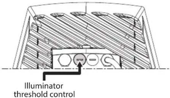
Pnc.31
Ocbetntelb Imeet BCTpoehhbl CymepeuHbI DaTnK, o6ecneuBaIOUa n ABToMaTHueCKoe BKJIIOUeHHe n BbIKIOUeHHe np 3aDaHHbIX ycIOBmX OCBeUeHHOCtN.
HactpoKa cyMepeHOrO daTnKa BbINOnHeHa npOn3BODInTelem, KOTOpbI 3apaHe yCTaHOBN yPOBeHb OCBeUeHN, NOxOJaunI dN 6oJbUnHCTBa KOHpypaun (OKoJIO 50 IIOKcOB).Ecn HxKHO BbICTaBtB nHbIe 3NaueHn NOPora cpa6aTBiBAHN, BbITaUNTe 3aRnykU, YCTaHOBneHHyU Ha 3aDHe N AcTn OCBETeJI, IN OcyuEcTBnTe HACTpoKc C NOMoub IO TBepTKN.
Iobopot noctpoeHoro pe3nCTopa no yacoboi cTpeKe npBedeT K 60one paHHem cybaTaBAHNIO HOHORO pexima (peeknoyeHne Ha 60one BbICOKoe 3NaueHne OCBeueHocHT). Iobopot noCTpoeHoro pe3nCTopa npOTUB YACOBoi CTpeKe npBedeT K 60one PO3dHemy cpaTaBbAHNO HOUHORo peXmHa (peeknoyeHne Ha 60one HN3Koe 3NaueHne OCBeueHocHT).
Pnc.32
Ioxntecb COOTBeTCTBHyUx yCNOuOBIO CBEeHHOCTN, NOxOJaXx IIN BKIOUeHn OCBETTeJ. MeJeHNOBOPaUNBaIte NODCTPOeHbI pe3NCTOp DO BKNIOeHn CBToNDoOB, YcTAHOBJIeHHbIX Ha 6OKOB CTOpOHe pe3NCTopa. KaK TOnbKO nOpOR cpa6aTBiBAHN 6yDet npEBiWeH (CBKIOUeHHbIMn CBTOIDoAMn), CnerKa IOBepHITe NODCTPOeHbI pe3NCTOp B O6paTHOM HAnpabJIeHN.

IIO 3aBepweHn HAcTpoKn npOBepbTe, yTO6bl 3aRnyuka 6bila nIoTHo BCTabHeHa o6paTHo dJa 0ececneHn repMeTuHocTn ycTPOcTBa.
7.10.3 PerynnpoBka MouHocTn CBeToNDNoHbIX OCBeTntTeNei

PpaBbIOOCBeTntEnb DOJKeH 6bITb BcerdaOTperyIuPoBaH Ha MUNHMaJIbHyO MOUHOCTb.
Ipon3BODntelh HAcTPOINOCBETNTb TaK,HTO6bl OH BbIaBaJ MaKcImaJIbHyIO MOUHCTb. EcNl Het HEo6xOIMOCTN B OCEWeJHn YdaJIeHHbIX OBekTOB NJI KApTINHka IOnyuaETcR CInuKOM CBETNOJ, UMeHbIHTe MOUHCTb, PnI 3TOM Bbl CHN3ITe NOTpe6JIeHne 3Heprnn.
Pnc.33
YdaIte repmetnuyu 3arnyuKy. NOBepHnte NOCTpoeuHbI pe3nCTOp no yacobO CTpeJIke, YTO6bl yBeJIuHTb MOUHOCTb INHpaKpaCHoro OCBETNTeI I nPOTNB YACOB O TpeKN, YTO6bl yMeHbUnTb ee.
MAX POWERMIN POWER
Pnc.34

IIO 3aBepseHn HAcTpoiKn npOBepbTe, UTO6bl 3aRnyuKa 6bila NIOTHO BCTabNeHa 06paTHO dJa OeCneueHn repMeTuHocTn yCTpoiCTBa.
7.11 Kpenenne ue TKe nCTeKnOooNCTnTeTn
Haene Tye Kky Ha oCb TeKoepKaTeJ.
YctaHOBNTe 电Ky B NOIOXKeHne NOKO.
Pnc.35
3aKpeNITe daHHbI eIeMeHT B c6ope c nOMOuBIO 1aH6bI rAkn.

Pnc.36

IpaBnIbHa HaCTpoiKa DoJXHa
No3BoJIaTb 1eTKe BepHyTbc8 B IcXoJHoe
IonoJxHe N npIneraTb K nlaCTUHe
Kopnyca.
8Включени

Y6eHNTecb, yTO yCTpoNCTBO n npOue KOMnHOHeTbI CNCTeMbI DOJXHbIM 06pa3oM 3aKpbItbI, yTO6bI ppeDToBpAteTb KOHTaKT C ChAETAMN, HxOJaUmmncr NOD HanpJxKeHnem.

Bo Bpempa60bI B HopMaIbHOM
peKIMe NOBepxHOCTb OCBeTtTeJI MOnKET
HaRpeBaTbCra DO BBICOKHX TemNepaTyp.
H36eraIte npAmoro KOtAKTa uYctAHOBHTe
yCTPOINCTBO B MeCTe, HeIOCTynHom dJa
NoCTOpOHnX NmU. Do OCBeTtEnJ MoXHO
doTparNBaTbCra TOnbKO NocNe TORO, KaOH
6yDet BBIKIOueH N OCTaJIeH OCTbIBaTb B
TeueHne KaK MNHMym 10 MNHyT.

He haxoNTecb pAOM c yctpoiCTBOM,ecnHa Hero noJaetc nTahme. IpopoBOnTe onepaunC yctpoiCTBOM Toblko npOTKIOUeHHOM NtAHm.

Y6eHNTecb B TOM, YTO BCE deTaIu HApExHo 3aKpEnJIeHbI.
IITTOYTO6BIBKIOUHTb yCTPOINCTBO,NOKIOUHTe NCTOHNNTAHNA.
TTO TO6bI BBKIOUHTb yCTPOINCTBO,OTKIOUHTe NCTOHNK NITAHN.
9 Konfugpaun
9.1 Be6-нтерфein

YCTPOIcTBO HAcTpoEHO TaKIM 06pa3OM, yTO6bl NOnyUHTb IP-aIpec OT cepBepa DHCP.

ПодэрхиBaembie 6pay3epbl (nocleня Верси): Microsoft Edge, Google Chrome™, Mozilla Firefox.

MAC-adpec 3aIncan Ha JpIbke IlaTbI ceHTpaIbHoro npouceccopa.
Pnc.37
IepBoe DeiCTBn E No HAcTpoNKe KOHfNrgpaunuycTpoNCTBa 3aKJIIOUaETcB N OJKnIOUeHN K Be6HHTEpFecy.
IP-apec, nonyuennb ype3 DHCP, moxho nocmOTpeB B aaine jyphana cepbepa DHCP.
Ecn cepBep DHCP HeoctyneH, yctpoiCTBO HactpanBaetc aBTOMaTnueeCKn, nCNoIb3yamocToTeJIbHO creHepnpoBAHHbI IP-aDpeCB noCteN 169.254.x.x/16.HaCtpoIka IP-aDpeCa KOMblOTepa B ToJ Xe NpOcTeN (npImep:IP-aDpec: 169.254.1.1, subnet mask: 255.255.0.0).
Дя посяку IP-aipeca yctpoiCTBa nCnoIb3yIte coBmecTmyc ONVIF nporpaMMy ynpabLeHn Bndeo (VMS) nIe CeTeBOA aHaJIINaTOp naKeToB (Chnphiep). (Pporpamma cKaHnpOBaHn IA).
YTo6bI NOyUHTb DOCTyn K Be6-INTeppeCy NOBOPOTHO rO yCTPOINCTBa, IpocTo NcNoJIb3yInTe 6pay3ep, YTo6bI NOKIIouHTbcr KaDpecy http:// ip_aDPEC n BblONHnTb BXoD B npINOxKeHne NOBOPOTHO rCTPOINCTBa C NOMOUsIO 3apaHee UCTaHOBJIeHHbIX yueTHbIX daHHbIX:
-Username:admin
- Napolb: admin
9.1.1 Haayalbna cTpaHnca (Home)
Ecnn aBtopn3aun npoJna ycneuho, oTo6pa3ntc nHTepfecn ynpabJeHn yctpoNCTBa.

Pnc.38
9.1.2 CtrpaHnca noJb3OBaTeJbcknx 3JIeMeHTOB ynpabNeHnA
YTo6bI ynpabTb ycTpoiCTBOM uepe3 6pay3ep, Bb6epnte fynkciuO User Control (NoIb30BaTeJIbckoe ynpaBHeHne).OTKpoEtc HOBoe OKHO CBnptyAblHO KnlaBnaTyPoI dIra BBOda KOMaHd.
Pnc.39
BnptyaIbHna KnaBHaIaTypa CoepKNT CneDyUOJIe 3JeMeHTbl ynpabLeHnIa:
- Nepeknouatelenb ckopocTee: N03B0JareT Bbl6paTbCKOPOCTb DBNKeHnnoBOPoTHoro yCtpoCTBa.

Pnc.40
- Zoom Wide/Zoom Tele


Pnc.41
Focus near/Focus far/Autofocus


Pnc.42
- Iris close/Iris open/Auto iris


Pnc.43
- Wiper/Washer


Pnc.44
Day:BkIIOueHneIK-phiNbTpaKaMepbl.Ppn HAnuNNOTKIIIOaETCBeTOINoIDhIEOCBETNTEN.

Pnc.45
Night:OTKJIIOUeHHeIK-ΦnIbTpKaMepbl.Pnp HAnuNN BKNIOuayet CBeTOINoIHbIe OCBETNTeIN.

Pnc.46
Visible Cut Filter On: BkIouaETnIbTp, OTEKAIOUIMBUNMbICBT (BMoJEnx, OCHAeHHbIX 3ToIyHKcneI).3TOTnIbTp NO3BOJAE TNOUYHTbYeTKOE N3O6paXeHHe (uepHo-6Jeoe) B nacMpyHy IoroDy nn npn BCTpeHOn 3acBETke.

Puc. 47
Visible Cut Filter Off: OTKJIIOUaET NIBTp,OTCEKAIOUH BUNIMbI CBET (B MOJELX, OCHASeHHbIX 3TOI YHKUnei.).

Pnc.48
Autopan:BkIouaet pexnM zIKNHyHOro P03nUHOPOBaHnBpaMKax DByx PpeBapNTeHbO yCTaHOBJIeHHbIX HaCTpoEKNI NOBOPTa,HaKIOHa N yBeJIuYeHn.
AUTOPAN
Pnc.49
- Scan Preset/Set Preset/Remove Preset
SCAN PRESET

SET PRESET

REMOVE PRESET

Pnc.50
Patrol:BknoyaetpekmnabTomatneckoro natapyuropoBaHn,NOBTOPOUeOcnaocneIOBaTeNbHbIMnnCnyaHbIM o6pa3OM, aTaKxpePdBaPntelHo yCTaHOBHeHHbte HaCTpOnKn NOBOPota,HaKIOHa NyBeInueHn.
PATROL
Pnc.51
BepHybcaHa domaunHIOCTpaHnUy
HOME
Pnc.52
9.1.3 Стравиca napametpoB yстpoiCTBa (Device Parameters)
IyHKT MeHIO IapameTpby yCTpoiCTBa (Device Parameters) no3BOJnEe 3aJaTB nMRAy UcTPOiCTBa IN npocmotpeTb dpYryo DOONHHTeJIbHyIO IHOpMaUIO.
Pnc.53
9.1.4 CtrpaHnua cTaTnCTnuecknx daHHbIX yCtpoiCTBa (Device Statistics)
B nyHKTe MeHIO «CtAnCTnKa yCTpoNCTBa» MOxHO npocMOTpeb BCE CTAInCTnueCKne daHHble, co6paHHbie BO Bpem pa6Otbl yCTpoNCTBa.
Device Statistics
| Pan degrees | 3364 |
| TB degrees | 1442 |
| Power up | 133 |
| Working hours | 26 |
| Heating/irr temperature (°C) | 40 |
| Heating/irr temperature (°C) | 65454 |
| Fan board/irr temperature (°C) | 40 |
| Fan board/irr temperature (°C) | 22 |
| CH/board/irr temperature (°C) | 43 |
| CH/board/irr temperature (°C) | 20 |
| Net board/irr temperature (°C) | 39 |
| Net board/irr temperature (°C) | 19 |
| IR Light On/Off | 0 |
Pnc.54
9.1.5 CtrpaHnua KOHfNrgypaun ciTn
NHT MEHOCETN (Network) NO3BOJAEr N3MEHNTb HAcTPOKNCETN NOBOPOTHOYCTPOINCTBa. 3Decb MOXHO pPnHrTB peWeHne, Tpe6yeTcA IN YCTPOINCTBY CTaTNueCKN aDPEC, DnHaMnueCKN aDPEC, NOyuaembl no npotoKony DHCP, nnn ABTomATuueCKN rHeepnpyEmbl aDPEC. YCTPOINCTBO NOdEpxkBaet INTepeHET-npotoKoI (IP) BepCm4.

Pp n aBtOMaTnueckn reHepnpyemom aDpece yCTpoiCTBO aBtOMaTnueckn Ha3NaHT ce6e aDpec B Dnana3oHe 169.254.0.0/16.
Ha 3toj Je cTpaHnue MoXHo HAcTpOuTb 2 DNSaDpeca n peuHTb, KaKne MexaHn3MbI CneJyETBKJIouHTb dJa aBTOMaTHueCKo NJeHTNΦHKaUnyCTpOuCTB B JOKaJIbHOcTeN.
Network Configuration
| IP Version | IPv4 |
| Address Type | STATIC |
| IP Address (IPv6) | 192.168.103.131 |
| Suer Mesh (IPv4) | 255.255.255.0 |
| Gateway (IPv4) | 192.168.103.1 |
| CNS meta-analysis | OBSERVED |
| Primary CNS | 评估失败 |
| Secondary CNS | 评估失败 |
| Date & Time | 2015-04-27 1:00:00 UTC |
| NTP Server | ENABLED |
| PC Specific | ENABLED |
| UPNP | ENABLED |
| Zaracal | ENABLED |
| Multicost discovery | ENABLED |
| WS discovery | ENABLED |

Pnc.55
NTP Server: MoXHo TaKKe yKa3aTb, Tpe6yeTcJn CnHxpoHn3nPoBaTb yCTpOoiCTBO C BHeuHm NTP-cepBepom (CteBbIM npOTOKoJOM BpeMeH).
- DISABLED: BbI6epnte 3Tu onuio, ecn Bbl He XOTITe CINHXPOHn3NpOBaTb DaTu N BpeMa yCTpoiCTBa.
DHCP: Bb6epnte 3Ty onuio,ecnBbXOTnte cnHxpoHN3npoBaTb DaTy u Bpemy yctpoiCTBa C daHHbIMN NTP cepBepa (IpotoKoI cTeBoro BpemeH),yka3aHHbIMN cepBepom DHCP. - STATIC: Bb6epnte 3TOT BapnaHT,ecn Bbl XOTNTe CnHxpoHn3npoBaT b DaTy n BpeMa yCTpOInCTBa C daHHbIMN NTP-cepBepa c 3aDaHHbIM CTaTnueckm aDpecom.

YTo6bI yCTpoiCTBO pa6oTano npabunbHo, Heo6xOaIMo CnHXPOH3NpuOBaTB erO c nporpaMMhblm 06ecneueHem VMS, nCnoJIb3yN TNP-cepBep.
9.1.6 CtrpaHnca nOJIb3OBaTeJIbCKNX HacTpoeK
IyHKT MeHIO User Configuration (IOnb3OBaTeJIbCKne HacTroPouKn) N03BOJRAET ynpaBnAe TaHHbIMN Bcex IOnb3OBaTeJe, IMeOuX DoCTyn K UcTPOINCTBy. IOnb3OBaTeJAM C npabAmn AdmHnCtpaTopa npedocTaBnEeTCs DOCTyn KO BcEM npaMeTpam KOHfNpyaun yctpoiCTBa. IOnb3OBaTeNi C npabAmn OepaTopa, IOnb3OBaTeJIa N AHOHMHOro IOnb3OBaTeJIa IMeOT OrpaHnueHHbI DoCTyn K CTpaHnCiM C fYHKUmaM YuPaBHeHn.

Pnc.56
HactpoJa KOHnrgpaunu yctpoiCTBa MoKet BbINOJIHTbcr TOnbKO NOb3ObaTeIaMn C npaBAMn aDMNHcTpaTopa.
9.1.7 CtrpaHnca napametpoB ABNXeHnA (Motion Parameters)
IyHKT MeHIO Movement Parameters (IapaMeTpbl DnHexeHn) N03BOJReT KOHTPOJINPOBaTB uepe3 INHTepHET BCE npaMeTpbl NOBOPOTHOY yCTPOJCTBa.
- Offset Pan: Поворотhoe устpoиCTBO IMeET MexaHueckn 3aHaHoe noLoXeHne 0^ .Функua CmeueHn npi nobopote (Offset Pan) no3BOnJeT yCTaHOBtB dpyroe noLoXeHne 0^ npi nomou nIporpaMMHoro obecneueHn.
Maximum Speed: YCTaHaBnBaet MaKcImaJIbHyIO CKOpOCTb pyHOro nepemeueHnra (Manual Speed). - Speed with Zoom: Пу ВКЛЮЧЕН 3ТОТ
параметр abTomatчecн снжаet ckopoctь
ПОВОРТОН YСТРОДТBA B COOTВETCBИС
Коэфицентом Macштабюваня.
Ko3ΦnueHT haknoHa (Tilt Factor): YcTaHabJIbBaET Ko3ΦnueHT yMeHbWeHnckOpOCTn pyuHoro nepeMeueHnra (Manual Speed) nOBepTuKaJIbHOJ OCU.
Pan Limits: BkIouaTe OpaHnueHn NOBopoTa.
Pan Start: YCTaHaBnBaet HaaybHyTOyKy NOBOPoTa.
Pan End: YCTaHaBnBaet KOHeuHyTOUky NOBOPota.
Tilt Start: YCTaHaBnBaET HaayabHyIO TOky HAKNoHa.
Tilt End: YCTaHaBnBaet KOHeuHyToTuKy HaKJIOHa.
Pnc.57
9.1.7.1 CtrpaHnca aBTOMaTnueckoro nahopamHoro ha6IoudeHna (Autopan Page)
IyHKT MeHIO ABTomaTuYeCKoe NaHOpamHoe Ha6JIoJeHne (Autopan) no3BOJnEeYka3aTb npEiBapuTeIbHO yCTaHOBLeHHbIe 3HaueHnI dJI BKNIOUeHnI OTKIOUeHnI aBTOMaTuYeCKOro naHOpamHoro Ha6JIOHeHnI.
Pnc.58
9.1.7.2 Ст相关政策 натуларовения (Patrol Page)
IyHKT MeHIO NaTpynipOBaHne (Patrol) no3BOJareYka3aTb IpeBapNTeBHO yCTaHOJIeHHbIe 3HaueHnIJa BKNUoyHnI OTKNUOyeHnI NaTpynipOBaHnI. MoXHo yKa3aTb, Ipon3BOJNTcA JN cKaHnpOBaHne IpeBapNTeBHO yCTaHOJIeHHo6Jlactn Ipon3BOJbHO ININ HbIM 6pa3OM.
Pnc.59
9.1.7.3 CtpaHnca Bbl30Ba DBNXKeHnA (Motions Recall)
IyHKT MeHIO Motion Recall (Bb3OB DnHexeHna)
no3BOJnRE yka3aTB BpeMeHHoINHTepBaIN pOcToR,
nocne KOTOPoro NOBOPOTHOe yCTpOiCTBO BbINOHNIT
ODHy n3 CNeDyUOuNX fYHKuN: BO3BpaueHne B
HCXoHDoe NonoJKeHne, Hauano naHopamHoro
Ha6liOHeHry nn Haayano NaTpynipObaHry.
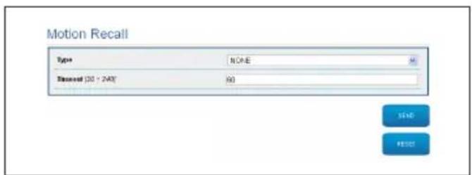
Pnc.60
9.1.8 CtrpaHnca npedBapntelbHO yCTaHOBJIeHHbIX npaMeTpOB
IyHK MeHIO Preset Parameters (IpeBapuTeNbHo yCTaHOJIeHHbIe npaMeTpbl) N03BOJAE T HAcTpaNBA Tb HEKOTOpbl NapaMeTpbl, OTHOCAUHXC K IpeBapuTeNbHbIM NaCTpoiKaM:
Scan Speed: Ckopoctb, n3Mepaemar B rpaaycx B cekyndy, npu KOTOpO IOCTnraeTcnpedBapntelHo yCTaHOBHeHHoe 3NaueHne B clyae npmoKOMaHbl onepaTopa.
Tyn yckopeHnra (Ramp type): N03BONaET BbI6NpaTb yckopeHne NOBOPoTHoro YcTPOJCTBa.
- Speed of Movements Default: CkopocTB, INCNoB3yeMaR npn aBTOMaTnueckOM NaHOpAMHom Ha6JIIODeHN n naTpynIpOBaHN.
Impose Default Speed:Испοльзуемя по умолчаню
CKOPOCTb TAKKE 6удET yCTaHOBJIeHa B KaueCTBe CКОРСТ
СКАнрOBаHN BO BCex ПpeДВapITeNbHbIx HAcTpoiKax.
DefaultDwellTime:CTaHdapTHOeBpemBaCekyHdx,B TeueHneKOTOPOYcTPONCBOpa6oTaETBpeXmEkaXdoIpeDbapntelbHOHaCTPOKN.
Impose Default Pause:ДЯ BCex npeBapntbHbIX NaCTpoE K IO yMOJIaHIO YCTaHABINBaETCn Nay3a.
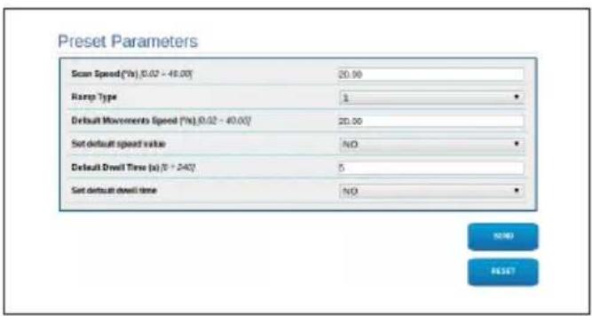
Pnc.61
9.1.9 CtpaHnca npedBapntbHo yctaHOBneHHbIX napametpoB (DOnonHHTeHbHOe MeHIO)
Bpa3deneIpeBaPnteBHO yCTaHOBHeHHbIe npaMeTpbl (DOnoHnTeBhIe) MoXHO HAcTPOHTb 3HaueHInr CKOpOCTn nay3bl IJI KAnDoI npaMeTpA, a TAKKe BKnIOuHTb INN OTKIOUHTb cAmIpeBaPnteBHO yCTaHOBHeHHbIe HaCTpOKN.
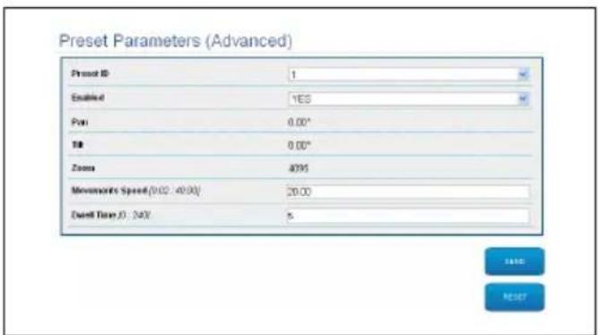
Pnc.62
9.1.10 Ctrpauca uΦpoBoro BxOda/ BvxOda (Digital I/O)
IyHKT MeHIO Digital I/O (UΦpOBOB BXOD/BbIXoD)
P03BOJRAET BbINONHATb HAcTPOK Ky KOHΦnIpyaun
IMeIOxCSr UΦpOBoBix KaHAnOB yCTpoIcTB.ДaJeE
PnIBOAnTCR KpaTKOE ONICAHne HaCTpaINBaEMbIX
NapaMeTPOB KaKdOrO UΦpOBOr BXoJa.
- Μηθινακατορ αβαριηнότος Αγίαλα (Alarm ID): ΑανΗοε Πολη ευπούβεγετσάν Βλήν Βυιδόρα Κρεύμετρος ΣχρορόΟν Βχόσα.
-
Type: Инд�示аць CTандарТHorO COCTORHIN [ \text{ифpoBOrO BXODa.} ]
Action: KaKdbi BxOJ MOXHO pINB3aTb K ONpeDeHOMy DeICTBnIO. DeIcTBne aKTNBnpyeTcR, KOrJa KOHTaKT HaxoNTcR B INoLOXKeHn, OTNIuHOM OT CTaNapTHoro. DocTyNhbIe DeICTBnI nepeUncJIeHbl Hnke: -
NONE (OTCYTCTBYET): Het déneCTbni.
SCAN (CKAH): Pacnonaraet NOBOPOTHOyCTPOIcTBOB COOTBETCTBUN CnpedBapuTeJbHOn HaCTPOIKoN.
PATROL: AktiBupyeT yHkCnIO PATROL (natpyu npoBaHne).
AUTOPAN (ABTOMATNUECKOE ПАHOPAMHOE HABJIIODEHNE): AKTNBUPyeT Функцию AUTOPAN (aBTOMATNueckoe панорamhoe Na6JIODeHne).
CTEKLOOCHNTENb:AKTUBnpyET CTEKLOOCHNTENb. - OmbIBATEJIb: 3anyckaet nocJeIOBaTeIbHOCtboOuNCTKn CTeKJa.
- PENE 1: AktuBupyeI pene 1.
- PENE 2: AktuBupyeT pene 2.
- IR FILT (ИК-ФИЛБТР): Быклioченue IVK-ФИЛБТра Камерbl. Рп Налчinn BKЛIOuaeСВЕТODиODнBLE OCBETNTeIN.
IpoBepka npabnIbHOCTn cpa6aTbIBaHnA abapnHbIX cnHaIOB OcyueCTBnaETcN C NOMOuTOUKN, nOBJIooJeCn Ha Be6-CTpaHnCe. B HopMaIbHOM pexmte ToyKa 6ydt 3eJeHo, a npn BblBHeHn CNrHaTa TpeBOrN -KpachOn.

9.1.11 CtpaHnua oMbIbTeJia
B nyHKTe MeHIO «MoeuHoe yCTpoiCTBO» MOxHO HAcTPONTb pa60Ty cIcTeMbI npOMbIBKn yCTpoiCTBa.
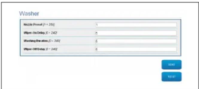
Pnc.64
9.1.12 Napametpbl KamepbI cTpaHnca

I3MeHeHne DaHHbIX B pa3dene «PpToKoN n ayeHTnΦuKaunra» MoKeT cdeNaTb KaMepy HeOCTynHO. 3aBODcKne HAcTpoiKN o6ecNeuBaIoT npaBnIbHbI NocTyN K cnCTeme.

PekomeHdyeTcH He n3MeHЯTb daHHbIe B pa3dene «XapaKTepeNCTnK JINH3», qTo6bl He hapuWntb npaBunbHoe fYHKUHOHPOBaHne cNCTembl. EdnHCTBeHHoe noJe3Hoe noJe dJa KOHeuHOro noJb3ObaTeIa - «ABTOΦOKyc»
B 3TOM pa3dene taKke OTO6paKaiaOTc DaHHbIe nO pa3HbIM npoФnIaM ONVIF, kCnpOpTuPoBaHHbIe n3 KaMepbl.
Camera Settings
| Protocol and Authentication | |
| Protocol | ON/F PROFILES |
| Username | servic* |
| Password | *** |
| Confirm password | *** |
| Streaming Profiles | |
| Profile ID | 0 |
| Profile | media_profile1 |
| Code | H.364 |
| Resolution | 1020 x 1080 |
| Frame rate | 30fps |
| Bitrate limit | 5000 kbps |
| GOP | 30 frames |
| Zoom enabled | No |
| Lenses Features | |
| Leasons | MOTORIZED |
| Zoom rate (° 35°) | 1 |
| Leasons positioning range (° 25°) | 20 |
| Motor Type | INVERTED POLARITY |
| Rotation polarity of the lens zoom | POSITIVE |
| Rotation polarity of the lens focus | POSITIVE |
| Rotation polarity of the lens iris | POSITIVE |
| IR Probe | EXTERNAL |
| Autobocus | MANUAL TRIGGER ONLY |

Pnc.65
YTo6bI n3MeHnTb HaCTpoiKn KaMepbl, HaxMnte KhoNkVTTunnel nnn npocTo Khonky Kamepa B MeHIO nHCTpyMeHTOB (9.1.13 CtpaHnca nHCTpyMeHTOB (Tools), ctpaHnca 28).
9.1.13 CtrpaHnca nHcTpymeHTOB (Tools)

B cnyuae c6poca PTZ BO3BpaaaetcK 3aBOJCKIM HacTpoiKaM. YTo6bl NOnyUHTb DOCTyn K CnCTeme, CneDyIte yka3aHnM B COOTBeTCTByIOuem pa3dene (9.1 Be6- nHTeppeic, cTpaHnca 21).
IyHKT MeHIO Tools NO3BOJRAET N3MeHARb IpeBapnteIbHO 3aDaHHble 3HaueHnB CEx npaMeTPOB KOHnRpyauu yCTpOuCTBa nn HeKOTOpbIX OTdEhBhIX rpynn npaMeTPOB.
DaaHaa rpynnnapaMeTPOB No3BOJAEt:
- O6HOBnTb npoWNBky yCTpoNCTBa.
- Npepe3anycnttbyyctpoiCTBO.
CkaaTe npnloKeHne VTTunnel, yTo6bI aKTHBnPoBaT coeHHeHne c IP-KamepoH, Heo6xOAnMoE dJa BxoJa Ha Be6-CTpaHnUy. (9.2 VTTunnel, cTpaHnua 30). - OtkpoIte Be6-cTpauNcy KaMepbI (9.3 Kamepa, cTpaHnua 30).
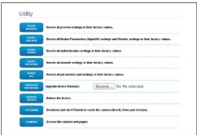
Pnc.66
9.1.14 Factory Default

EcnnapoIb DocTypa K nobopoTHoI onope yTepaH, Bbl MoKeTe BocCTaHOBtB 3aBOdCKne HAcTpoiKN C NOMOuBIO KHOpKN Reset (C6poc), pacnoLoXeHHoB BVHTPN u3dennia.

Для Nonckaи nndeHTnФнkaци NOBOPOTHоI ONOpbl cIeDyIte yKa3aHnYM В COOTBeTCTByIOUe m pa3dene (9.1 Be6- mHTeppeic, cTpaHnua 21). Ondako B ЗTom сIучae ДЯdoCTyna K cnCTeMe Heo6xOIMMo NCNoJIb3OBaTb yYeTHbIe daHHbIe KaMepbl, a He NOBOPOTHоI ONOpbl. Ecnn NcNoJIb3yIOTc yYeTHbIe daHHbIe KamepbI no yMOnUaHnIO (yCTaHOBJIeHHbIe Videotec), onH cIeDyIOUne:
Login: service
Password: Videotec2020-
YTO6bI BOCCTaHOBNTb 3aBOdCKne HaCTpoiKn, OTHOcAunecK CetN,IOCTyNy NOnb3OBaTeNn KOHfNpyaoun KamepbI,BblONHInTe CneDyUoune DeiCTBn:
-Подклочenteустрочькетиэл ektpoNTaHЯ.
- OTkpoIe KpbIshky DIP-nepeKlnuOaTeJe.
- HainTe DIP-nepeKIOUaTeIb 4 (01).Onycnte nepeKIOUaTeIb 1 Bn3, B noJIoXeHne 1 (ON).
-ДождntecbВрemeHHOrOOTKlHueHnCBeToDnOdB(02).
-ПоднIMTe nepeKIOUaTeIb 1 BBepx,В
полЖeHne 0 (OFF).
3aKpOTe KpbIuKy pa3bema.
CneyuTe yka3aHnM, n3NoXeHHbIM B naparpafe 9.1, uTo6bl onpeJeNTb aIpec (9.1 Be6-nHTepfec, cTpaHnca 21).
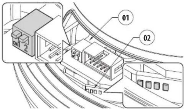
Pnc.67
Tpe6yemblnnapaMetpbI:
- IP-npotoKoN, nCnoB3yeMbI dIa CBA3n C KaMepoI (ONVIF PROFILE S).
Tyn yctahOBnEHORo o6bekTNBa (MOTOPU3OBAHHbl).
-УчETье Даньe, Heo6xOДмьe ДЯ ПОДКЛЮЧЕНИ K IP-KaMEpe (username:"service"; password:"Videtotec2020-"). - Ipezeanyctnty yctpoiCTBO.
- EcnBce eue yctaHOBnEH DHCP, Bo3MoXHo, aDpeu 13dennr n3MeHnncr.
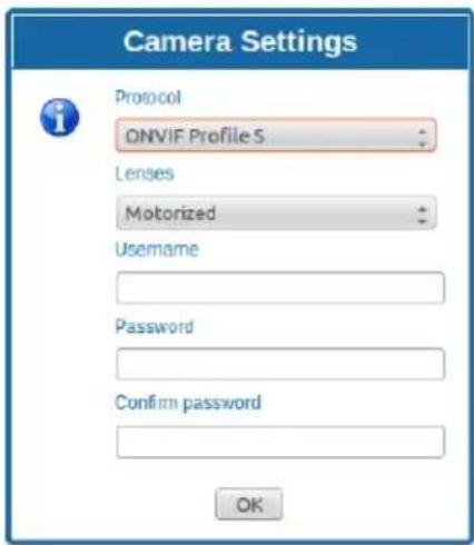
Pnc.68
9.2 VTTunnel

PpunoxeHne pa6oTaet TOnbko c JavaTM. Ecn JavaTM He yctaHOBnHa, 3arpy3nte nocneHIO BepCIO C caNTa www.java.com.

PpIIOxHHe MoXHO NOKIOUHTb TOnbKO K nepBOMy INTepeCy cetn. K NOBOPOTHomY yCTpoiCTBy DOJXeH 6bITb NOKIOUeH TOnbKO CeTEBO Ka6eJIb.

ДлгТOrOуTO6bI3aNyCTnTb npnIoXeHne, Tpe6yOTcI npaba adMnHnCTpaTopa KOMnbIOTepa.Ha3KpaHeMoKetNoRbNTbcr cNeDyUoSee coo6uHene:You have to executeJavawasadministrator(Bbl DOnKhbI3aNyCTnTbJavawOTmMeHn adMnHnCTpaTopa).B3tOMcnyae Heo6xOdmoN3MeHnTb CBOIcTBa3aNycka faiJaBvYCTaHOBOUHONnanKeJava.
UTo6bI NOdKIOuHTb Be6-KaMepy, Heo6xoIMO
UCNoB3OBaTb nporpaMMy VTTunnel, DocTyNHyO B
MeHIO Tools.
Korda nporpamma 6ydeT 3anyueHa, oTo6pa3ntcra cncoK ceTeBbix yctpoiCTB. YTo6bl NpDKNIOuHTb KaMepy, BbIepeHte Heo6xoJmOe NOBOPOTHOe yCTPOICTBO n HaxMtTe Ha KhONKy Connect (NoKnIOuHTb).
Iocne toro kaK coeHHeHne 6yTe yCTaHOBNeHo, Bbl cMOKeTe 3aHTn Ha Be6-CTpaHnCy IP-KamepbI no aDpecy 192.0.0.64.
Iocne 3aBepweHnpa60TbICKaMepoB Bbl MOKeTe 3aKpbITb NOkJIIOUeHHe,HaXaB Ha KHOKNy Disconnect (OTKnIOuHTb).POkNIOUeHne MoxHo OcyueCTBnTb TOnbKO K OJHOH KaMepe 3a pa3, POToMy Heo6XoIMO OTKnIOuHTbcr OT NOBOPOTHO yCTpOInCTBa nepeD TeK, Ka IpeEITK pa6Ote Ha dpyrom yCTpOInCTBe.
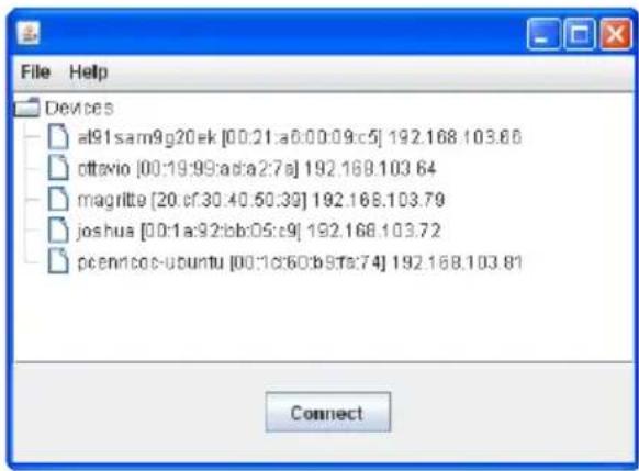

Pnc.69
Ipee3anyctte NOBOPOTHoe yCTpOCTBO, ecnnapaMeTpbl BundeONOTOKa 6bln n3MeHeHb BO BpeM KOHpyaun KaMepbl.
9.3 Kamepa

Bone noDpo6HyIO nHΦopMaunio CM. B pyKOBODCTBe K Kamepe, KOtopyO MOxHO 3aRpy3ntb C Be6-caNTa.

YTo6bI NOnyUHTb DOCTyn K MeHIO KaMepbl, y NobopoTHo ONOpbl He DoJXHO 6bITb aBTOMaTnueckn CreHepuPoBaHHoro aDpeca nn B DHCP.
OtkpoTe Be6-CTpaHnUy KaMepbl.
HENCPABHOCTb YcTpoNcTBo He BkIouaTeCra.
ПИЧИHA HenpaBnIbHbI MOHTaX
npOBoDKn, cROpeBwHm
npedoxpaHntJIb.
PEUJEHNE Y6eINTEcB TOM,TO
COeINHeHnBbINONHeHbI
HadJIeXaIIM O6pa3OM.
PpOBepbTe npaBnIbHOCt b
pa60tI npedoxpahntenei,
PnBbIXOe npedeoxpaHnten
I3CTPO3aMeHHTeHXHa
npedoxpahnteynka3aHHbIX
MOdJIeI.
HENCPABHOCTb Ppu 3anycke noBopoTHoe yctpoiCTBO OTKJIUOyeNo.
HENCNPABHOCTb KaMepa He oKycnpyeTcAdoJXHbIM 6pa30M
ПИЧИHA HacpoиKaMepbI HapyuWeHbI
PEUJEHNE O6paTntecb Cnyk6y
PondepkNnOJyueHnYka3aHn
NO BbIOnJIeHNIO O6paTHoN
fokycnpobkn.
HEUCNCPABHOCTb Prn Hn3KoT TemnepaType NOTOKOBoe BvdeO
Heoctynho, MHorne nyHKtbl
MeHIOOTKJIIOUeHbI.
PNUHNA CnCTema Bce ue HaxoNTcB
ctadynydaennybda(o6bHNO
PnBODc3y6aTbIMpeMHem
KoHTaKTHoe KOJIbUcO
3JIeKToHHbIe OrpaHnUHTeIN NOBOPoTa
HyneBOn 3a3Op
Ontnueckne daTunKn dIaTOHOro nO3nOHOHPOBaHn
BCTpoHbI CTeKJIooOuNCTnTeNb
IpeBapntbHNo yctaHOBHeHHa KaMepa N o6beKtNB
15.2 MexaHnueckne xap.
I3rotabJINBaETcN3aJIOMHHnI INTexHOJINMepa
3nOKcINoJIIn3ePoBOe nopoKOBoe nokpbITne, CBET RAL9002
BpaueHne no ropn3oHTaII: 360^ ,noCToHHbIM BpaueHne
YBeHnueHne 33x:
- BéptιkaJIbHoe nepemeUeHHe: ot -20° do +45°
- Ckopoctb ropn3oHTaJIbHOrO dBIXeHnA (perynpy etc): ot 0.02^ / s do 20^ / s
- CkopoocTb BepTuKaJIbHOro nepemeueHnra (perynn pyeTc): ot 0.02^ / s do 20^ / s
ToUHOCbIpeBapuTeJIbHO yCTaHOBHeHHbIX noJoxKeHn:0.02°
Ka6eBbHbIe MyfTbI:3xM16
Bec yctpoiCTBa: 30kg
15.3 Θл ektpиескne yap.
Hanpajekhe cetu nHTaHn/Notpe6JEmbI TOK:
230Vac, 0.4A, 50/60Hz
120Vac, 0.8A, 50/60Hz
24Vac, 4A (8A CO CBETOДNOДHBIMN OCBETITeJIaM), 50/60Hz
3HeprOTope6JIeHHe (OCBETeIN BbIKIOueHbI):
24W, NOBOPOTHOe yCTPOIcTB OCTaHOBJIeHO (OJIN DaHHe), NODORpeB BbIKJIIOUeH
100W, NOBOPOTHoe yCTpOJCTBO B DnHexeHHN, noDorpeB BKIOUey
3HeprnonoTpe6JeHne(BKJIIOUeHHbIe OCBTeTIeN):
150W, NOBOPOTHoe yCTPOIcTB O B DnIXeHN, NOIOrpeB BKIOUChE, OCBETNTEIN Ha MNHMaJIbHyIO MOUHOCTb
190W, NOBOPOTHOE yCTPOICTBO B DUNJKeHNN, NODORpeB BKIOUeH, OCBETNTEN Ha MaKcIMaJIbHOH MOUHOCTN
4 BXOda CnHaIa TpeBOrN CaABTOHOMHbIM NCTOCHNKOMIITaHIN
2 cyxnx KOHTaKaTa: 30Vdc max nJn 30Vac, @ 1A
15.4 CBra3b (Communications)
Pa3bem: RJ45, 10BASE-T/100BASE-T
IpoToKoI: ONVIF, Profile S (TCP/IPv4, UDP/IPv4, HTTP, NTP, DHCP, WS-DISCOVERY, QoS, RTSP, RTCP, RTP)
15.5 Kamepbbl
"Дeнь-Ночь" Full HD, 60 kaДров/c, sensor CMOS 1/2.8"
3ΦΦeKTHBHeIπKcEJI:2Megapixel
MnHmMaIbHoe OcBeueHne, ZBeTHoe (ICR BvIKIOueH):
0.041 lx 1/25s F3.0, 50 IRE
MnHmMaIbHoe ocBeueHne, Y/B (ICR BkHoueH):
0.005lx1/25sF3.0,50IRE
YBeJIuHHeN33x:
- Topu3oHTaIbHbI yroI o63opa: ot 20.51° (wide end) do 0.65^ (tele end)
- BéptɪkaJIbHoe nolé o63opa: ot 11.58^ (wide end) do 0.36^ (tele end)
OTHOWeHne cInrHaJ-Imm:6OJIe 55 dB
PacunpeHbI dHaMnueckn dnaana3OH:110dB WDR (U3MepeHO B COOTBeTCTBUN c IEC 62676 qactb 5)
IapameTpbl NaCTpoiKn n3o6paXeHn: KoHTpact (Contrast), HacbiueHHocTb, JRPKocTb
BaIaHc 6enoro (White Balance): ot 2500K do 10000K, 4 aBToMaTnuecknx pexkma (ocHOBaHne, standard, HATPnEBAJ lamna, npeo6nadaIOuOuI nuBeT), pexIM «PyuHoN» n pexim «YdepXaHne»
UpoBHeh ALC: PerynpemybIi
HacbIeHHocb: PerynnpyeTcra OT NIKOBOn do cpeHnei
3aTBOP: ABTomatueckn 3neKtpoHbI 3aTBop (AES, Automatic Electronic Shutter); ΦικυροBaHHa BbidepKa (oT 1/25 [30] do 1/15000)Bb6npaEmbI; UcTaHOBka BbidepKKn NO yMOnuHaHIO
"Дeнь-Ночь": Auto (HactpanBaemble TocKn NepeKJIIOU eHn), CBeTHoN, MOHOxPOMHbI
Sharpness: Bb6op ypoBn yCnJIeHn pe3KoCTn
KomneHcaunBCTpeuHoi 3acBeTKn:Bk./ BbIKI./ HHTeJIeKTuaybHa aBTOMaTueckaJ EKCNo3uCiN (IAE)
ONTMn3aun KoHTpactHocTn:Bk./BbIKJ.
Iopablenne nomex:HTenKeTyaIbHoe dHAMueckoe npableneHne nOMEXOTdJIbHbIMBpeMeHHbIMN pOCTpaHCTBeHHbIMNaCTPOkamn
Intelligent Defog
Video Content Analysis Intelligent Video Analytics
CIOXeTHbI pexIM: 10 npedyctaHOBJeHHbIX
pexIMOB cIIaHnropUzIKOM:B nOmeueHN,
Ha yInue, TpaHcnpTHeo coo6uHne, Cna6oe
OCBeSeHne, HHTeJIeKTuJbHaE EA,Bn6paun,
HN3KaA CKOpocb IpeJaUn DaHHbIX,CnOPT NIrpbl,
MaRa3INbI, paCno3HaBaHne HomepHbIX 3HaKOB (LPR)
3aTeMHeHne yuactKOB
15.6 06beKTHBbl
YBeHueHe 33x,15.2-500mm,F3.0 (CnCTema TepMOKOMHeHcaunuN HbTp,OTceKaUoun BNDIMBI CBET)
15.7 Okpuyaioa cpea
- ULISSE RADICAL
- Contents
- About this manual 5
- Notes on copyright and information on trademarks 5
- Safety rules 5
- Identification. 8
- Versions 9
- Preparing the product for use 9
- Installation 12
- Switching on 20
- Configuration 21
- Accessories 31
- Maintenance 33
- Cleaning 33
- Information on disposal and recycling 34
- Troubleshooting 34
- Technical data 35
- Technical drawings 37
- About this manual
- Typographical conventions
- DANGER!
- CAUTION!
- INFO
- Notes on copyright and information on trademarks
- Safety rules
- Identification
- Product description and type designation
- Product marking
- Checking the markings
- Versions
- LED illuminator
- Preparing the product for use
- Safety precautions before use
- ATTENZIONE!
- AVERTISSEMENT!
- Removal of the protective packaging
- Housing opening
- Remove the protective packaging
- Contents
- Safely disposing of packaging material
- Preparatory work before installation
- Mounting the bracket
- Cables management
- Installation
- Connection of the cables to the base
- Fixing the base to the support
- Connector board description
- Connection of the power supply line
- 24Vac power line connection
- 120Vac and 230Vac power line connection
- Connection of the alarm inputs, of the twilight switch and of the relays
- Connection of the Ethernet cable
- Fixing the upper body
- Counterweights installation
- LED illuminators installation
- Counterweight removal
- Fitting the illuminator on the bracket
- Connection of the LED illuminators
- LED illuminator activation and adjustment instructions
- Description of the LED illuminator
- LED illuminator switching on threshold adjustment
- LED illuminator power adjustment
- Fastening of the wiper blade
- Switching on
- Configuration
- Web interface
- Home Page
- User Controls page
- AUTOPAN
- Device Parameters Page
- Device Statistics Page
- Network Configuration page
- User Configuration page
- Motion Parameters Page
- Autopan Page
- Patrol Page
- Motions Recall Page
- Preset Parameters page
- Preset Parameters page (Advanced)
- Digital I/O Page
- Washer page
- Camera Settings page
- Camera Settings
- Tools Page
- Factory Default
- VTTunnel
- Camera
- Accessories
- Washer
- Washing system connection
- Wall mount bracket
- Parapet bracket
- Power supply with illuminator control
- Maintenance
- Fuses replacement
- Cleaning
- Cleaning the window and plastic parts
- Information on disposal and recycling
- Troubleshooting
- PROBLEM The product does not go on.
- PROBLEM During start-up the pan & tilt is disabled.
- PROBLEM The camera is not focusing correctly
- PROBLEM At low temperatures, video streaming cannot be reached, many items on the menu are disabled.
- Technical data
- General
- Mechanical
- Electrical
- Communications
- Cameras
- Lenses
- Environment
- Certifications
- Technical drawings
- Pagina Home
- Accessori
- Support fixation murale
- Support fixation sol
- Abb.42
- Abb.43
- Abb.44
- Abb.53
- Птумейня В OTHOSEHn ABTOPCKOtro празви Инфорmaцnia O TOPROBbIX Маркax
- ПравILA Тхнки 6e3oNaCHOCTN
- 06o3haueHne
- Onicahne n 6o3naueHne Tnpa yctpoiCTBa
- Mapknipobka n3delen
- Pnc.1
- Ka6eNbHa yKnaJaKa
- MoHTaX
- Повлочни kaбелк OCHOBAHIO
- KpenJIeHne OCHOBaHnK OonopHOJ KOHCTpyKcIIN
- Pnc.12
- Pnc.13
- OnscaHne nlaTbI pa3beMOB
- YctaHOBka OCBeTnteHa KaPOnuTeHne
- Повлочи Светоюньх Oсвети
- PerynilpoBka n pexnM BkIIOueHna CBeToNDnOHBIX OCBeTnteIeI
- OnncanHe cBeToIIOHOrO OCBeTITeJIa
- PerynilpoBka nopora BkIoueHncaCBeToNDNbIX OCBeTHTeJIe
- Pnc.31
- Pnc.32
- PerynnpoBka MouHocTn CBeToNDNoHbIX OCBeTntTeNei
- Pnc.33
- Pnc.34
- Kpenenne ue TKe nCTeKnOooNCTnTeTn
- 8Включени
- Konfugpaun
- Be6-нтерфein
- Haayalbna cTpaHnca (Home)
- CtrpaHnca noJb3OBaTeJbcknx 3JIeMeHTOB ynpabNeHnA
- Pnc.39
- Pnc.40
- Pnc.41
- Pnc.42
- Pnc.43
- Pnc.44
- Pnc.45
- Pnc.46
- Puc. 47
- Pnc.48
- SCAN PRESET
- SET PRESET
- REMOVE PRESET
- PATROL
- HOME
- Стравиca napametpoB yстpoiCTBa (Device Parameters)
- CtrpaHnua cTaTnCTnuecknx daHHbIX yCtpoiCTBa (Device Statistics)
- Device Statistics
- CtrpaHnua KOHfNrgypaun ciTn
- Network Configuration
- CtrpaHnca nOJIb3OBaTeJIbCKNX HacTpoeK
- CtrpaHnca napametpoB ABNXeHnA (Motion Parameters)
- CtrpaHnca aBTOMaTnueckoro nahopamHoro ha6IoudeHna (Autopan Page)
- Ст相关政策 натуларовения (Patrol Page)
- CtpaHnca Bbl30Ba DBNXKeHnA (Motions Recall)
- CtrpaHnca npedBapntelbHO yCTaHOBJIeHHbIX npaMeTpOB
- CtpaHnca npedBapntbHo yctaHOBneHHbIX napametpoB (DOnonHHTeHbHOe MeHIO)
- Ctrpauca uΦpoBoro BxOda/ BvxOda (Digital I/O)
- CtpaHnua oMbIbTeJia
- Napametpbl KamepbI cTpaHnca
- CtrpaHnca nHcTpymeHTOB (Tools)
- Kamepa
- HENCPABHOCTb YcTpoNcTBo He BkIouaTeCra.
- HENCPABHOCTb Ppu 3anycke noBopoTHoe yctpoiCTBO OTKJIUOyeNo.
- HENCNPABHOCTb KaMepa He oKycnpyeTcAdoJXHbIM 6pa30M
- HEUCNCPABHOCTb Prn Hn3KoT TemnepaType NOTOKOBoe BvdeO
- MexaHnueckne xap.
- Θл ektpиескne yap.
- CBra3b (Communications)
- Kamepbbl
- 06beKTHBbl
- Okpuyaioa cpea
Brand : Videotec
Model : Ulisse Radical
Category : Surveillance Camera