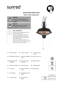
Atria - Heating SunRed - Free user manual and instructions
Find the device manual for free Atria SunRed in PDF.

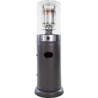
| Product type | Outdoor radiant heater |
| Brand | SunRed |
| Model | Atria |
| Fuel | Propane/butane gas (LPG) |
| Total height | 2150 mm |
| Weight | 28 kg |
| Ignition | Electric pulse ignition (AA battery) |
| Gas bottle type | LPG bottle max 10 kg (diameter ≤ 31 cm, height ≤ 66 cm) |
| Gas hose | Rubber, length 60 cm, CE certified, resistant from -20°C to 80°C |
| Gas pressure (regulator inlet) | Max 100 PSI |
| Materials | Steel with powder coating, glass tube, stainless steel reflector |
| Usage | Outdoor only, in a well-ventilated area (≥25% open surface) |
| Safety distances | Top: 45 cm, sides: 70 cm from combustible materials |
| Main functions | Infrared, variable gas inlet valve, adjustable reflector |
| Maintenance | Clean exterior with warm soapy water; check for leaks with soapy solution |
| Storage | Vertical, sheltered from weather, temperature <50°C |
| Included spare parts | Reflector, top plate, glass tube, burner, tank, wheel, screws |
Frequently Asked Questions - Atria SunRed
User questions about Atria SunRed
0 question about this device. Answer the ones you know or ask your own.
Ask a new question about this device
Download the instructions for your Heating in PDF format for free! Find your manual Atria - SunRed and take your electronic device back in hand. On this page are published all the documents necessary for the use of your device. Atria by SunRed.
USER MANUAL Atria SunRed
Manual Square Flame Torch (UK)
Handleiding Flame Torch (NL)
natural_image
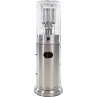
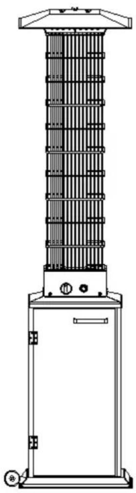
Exterior view of a tall outdoor heating tower with visible heat source and grid structure (no text or symbols)Certified by international recognized standards.
The infra-red with heat wave outdoor heater.
Variable control gas valve with electric pulse Igniter.
Steel with powder coated or stainless steel.
2150mm total height.
Cover with extend warming area.
Please keep this manual for future references
Manual Square Flame Torch (UK)
natural_image
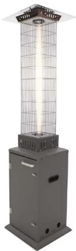
Exterior view of a portable outdoor heating tower with vertical metal frame and control panel (no text or symbols visible)Certified by international recognized standards.
The infra-red with heat wave outdoor heater.
Variable control gas valve with electric pulse Igniter.
Steel with powder coated or stainless steel.
2150mm total height.
Cover with extend warming area.
Please keep this manual for future references
WARNING
- Read the instructions before installation and use.
● This appliance must be installed and the gas the gas cylinder stored in accordance with the regulations in force.
● This appliance requires installation by a competent person. - For use only in well-ventilated areas. An amply ventilated area must have a minimum of 25% of the surface area open. The surface area is the sum of the walls surface.
● The use of this appliance in enclosed areas can be dangerous and is prohibited.
● This appliance shall be not used for the heating of domestic premises.
● This appliance shall be used for space heating only.
● This appliance shall not be used in basements or below ground level. - This appliance has no atmospheric sensing device. It shall be used for heating well-ventilated buildings used for animal rearing, or for outdoor use only.
● Use only the type of gas and the type of cylinder specified by the manufacturer. - Do not place items on or against this appliance.
- Do not store chemicals or flammable materials or spray aerosols near this appliance.
- Do not operate this appliance in an explosive atmosphere like in areas where gasoline or other flammable liquids or vapors are stored.
- Protect the hot glass tube from rain, water splash or anything that will cause a sudden change in temperature which may lead to cracking or shattering.
WARNING
● Turn off the gas valve immediately if smell of gas is detected.
● Extinguish any open flame.
- If odor continues, contact your gas supplier immediately.
WARNING
The user assumes all risk in the assembly and operation of the gas heater. Failure to follow the warnings and instructions in this manual can result in severe personal injury, death or property damage. If user cannot read or fully understand the instruction manual, please contact your dealer. Manufacturer or supplier will not be responsible for user's negligence.
CAUTION
● Installation and repair should be done by a qualified service person.
- Improper installation, adjustment, alteration can cause personal injury or property damage.
- Do not attempt to alter the unit in any manner.
● This appliance must be installed and the gas cylinder stored in accordance with the regulation in force.
- Do not move the appliance when in operation.
● Shut off the valve at the gas cylinder or the regulator before moving the appliance.
● The tubing or the flexible hose must be changed every year.
● In case of violent wind particular attention must be taken against tilting of the appliance.
- Do not store or use gasoline or other flammable vapors or liquids into the heater unit.
● The whole gas system, hose regulator, pilot or burner should be inspected for leaks or damages before use.
● All leak tests should be done with a soap solution. Never use an open flame to check for leaks.
- Do not use the heater until all connections have been leak tested.
● Turn off immediately the gas valve if smell of gas is detected.
- Do not transport the heater while it's operating.
- Do not move the heater after it has been turned off until the temperature has cooled down.
- Keep the ventilation opening of the cylinder enclosure free and clear of debris.
- Do not paint radiant screen, control panel or top canopy reflector.
● Control compartment, burner and circulation air passageways of the heater must be kept clean.
● Frequent cleaning may be required as necessary.
● The LP tank should be turned off when the heater is not in use.
- Check the heater immediately if any of the following exists:
- The heater does not reach temperature.
- The burner makes popping noise during use (a slight noise is normal when the burner is extinguished).
-
Smell of gas in conjunction with extreme yellow tipping of the burner flames.
-
The LP regulator/hose assembly must be located out of pathways where people may trip over it or in area where the hose will not subject to accidental damage.
- Any guard or other protective device removed for servicing the heater must be replaced before operating the heater.
● Change the gas cylinder in a well ventilated area, away from any inflammation source. - Check that the regulator seal is fitted and that is in good condition.
- Do not obstruct the ventilation holes of cylinder housing.
● Adults and children should stay away from high temperature surfaces to avoid burns or clothing ignition.
● Children should be carefully supervised when they are in the area of the heater. - Use may replace the rubber hose by himself and note the length of the hose is 60cm. And the hose must be required by the national conditions.
● LP Characteristics-Flammable, explosive, heavier than air-settles in low areas. - In its natural state, propane has no odor. For your safety, an odorant is added that smells like rotten cabbage.
- Contact with liquid LP can cause freeze burns to skin.
● This heater is shipped from the factory for Propane, Butane and their mixture (commonly called LPG) use only - Use only 10kg(Dia. can not exceed 31cm & Height can not exceed 66cm) LP gas cylinders conforms to local regulation in force (same as commonly used on gas grills) with safety valves.
- When heater is not in use, turn Control Valve OFF. Close the valve of the gas cylinder or the regulator after use.
● The use of this appliance in enclosed areas can be dangerous and is "PROHIBITED"
1) For use outdoors or in amply ventilated areas.
2) An amply ventilated area must have a minimum of 25% of the surface area open.
3) The surface area is the sum of the walls surface.
natural_image
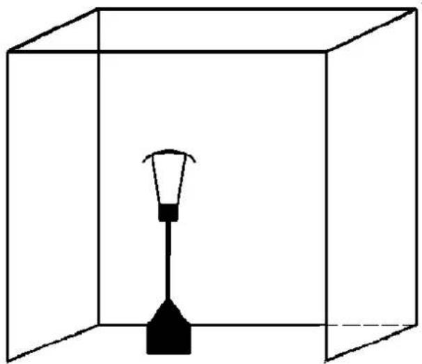
Simple line drawing of a lamp inside a transparent cube (no text or symbols)Warning:
● Never use the heater while it is raining, the glass tube would break when it suddenly met water
● Always turn off the heater while there is a rain.
● Never splash any liquid to the glass tube when the heater is working
● The glass tube will be extremely hot when it is working. Never try to touch it and keep the children away from the heater
● Always ensure the heater stands firmly, the glass tube may break if the heater was fell down onto ground.
● Never use the heater if the glass tube has any crack
HEATERS STAND AND LOCATION
● The heater is primarily for outdoor use only. Always ensure that adequate fresh air ventilation is provided.
● Always maintain proper clearance to combustible materials, i.e. top 45cm (18") and sides 70cm (28") minimum
● Heater must be placed on level firm ground.
● Never operate heater in an explosive atmosphere like areas where gasoline or other flammable liquids or vapors are stored.
GAS REQUIREMENTS
● Use propane, butane, propane and butane mixture.
● Maximum inlet pressure of regulator must to exceed 100 PSI.
● The pressure regulator and hose assembly to be used must conform to local standard codes.
● Use correct pressure regulators conform to local regulation in force and specification in page 7 of this manual.
- The installation must conform to local codes, or in the absence of codes, with the standard for storage and handling of liquid petroleum gases.
● A dented, rested or damaged propane tank may be hazardous and should be checked by your tank supplier.
● Never use a propane tank with a damaged valve connection.
● The propane tank must be arranged to provide for vapor withdrawal from the operation cylinder.
● Never connect an unregulated propane tank to the heater.
● The rubber hose which connect the regulator and inlet should not longer than 60 cm
● The rubber hose should be got CE approval, and heat resistant should be between-20°C to 80°C
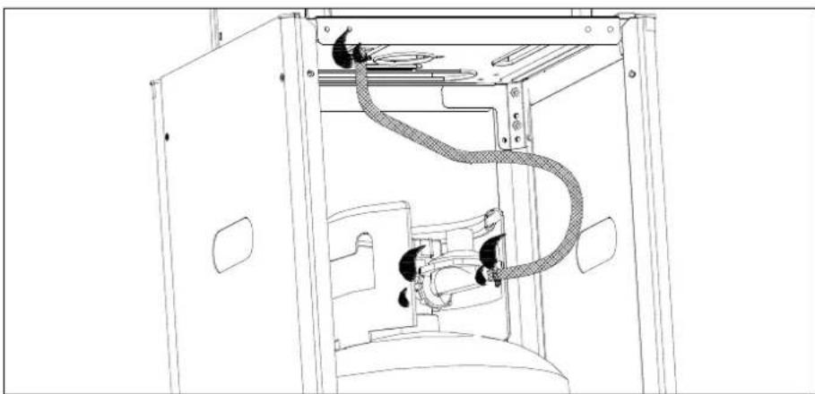
LEAKAGE TEST
Gas connections on the heater are leak tested at the factory prior to shipment. A complete gas tightness check must be performed at the installation site due to possible mishandling in shipment or excessive pressure being applied to the heater.
- The heater must be checked with a full cylinder.
- Make sure the safety control valve is in the OFF position.
- Make a soap solution of one part liquid detergent and one part water. The soap solution can be applied with a spray bottle, brush or rag.
- Soap bubbles will appear in case of a leak.
- Leakage test points. See pictures below.
- Turn the gas supply ON.
- In case of a leak, turn off the gas supply. Tighten any leaking fittings, then turn the gas supply on and recheck. Contact your dealer for assistance if bubbles continue to appear.
• Never leak test while smoking.
natural_image
Technical line drawing of a mechanical assembly with internal components and no visible text or symbolsFUEL GAS ODOR
LP gas and natural gas have manmade odorants added specifically for detection of fuel gas leaks. If a gas leak occurs
you should be able to smell the fuel gas. Since Propane (LP) is heavier than air you should smell for the gas odor low to the floor. ANY GAS ODOR IS YOUR SIGNAL TO GO INTO IMMEDIATE ACTION!
- Do not take any action that cloud ignite the fuel gas. Do not operate any electrical switches. DO not pull any power supply or extension cords. Do not light matches or any other source of flame. Do not use your telephone.
• Get everyone out of the building and away from the area immediately. - Propane (LP) gas is heavier than air and may settle in low areas. When you have reason to suspect a propane leak, keep out of all low areas.
- Use your neighbor's phone and call your fuel gas supplier and your fire department. Do not reenter the building or area.
- Stay out of the building and away from the area until declared safe by the firefighters and your fuel gas supplier.
- FINALLY, let the fuel gas service person and the firefighters check for escaped gas. Have them air out the building and area before you return. Properly trained service people must repair any leaks, check for further leakages, and then relight the appliance for you.
OPERATION
LIGHTING INSTRUCTIONS
Check and ensure that an AA battery is inside the ignition chamber And has power. Ensure the anode (+) faces outside.
natural_image
Top-down schematic of a device casing with internal components (no text or labels)TO TURN THE HEATER
- Turn on the valve on the gas supply cylinder completely.
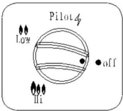
- Push the control knob in it and turn it the "pilot" position.
- Press the "igniter" button several times to light the burner. Hold it for 5 seconds. Release the Control Knob after the burner lights.
- Turn the Control Knob to switch to desired temperature position.
·Turn the knob to "LOW" position for small flame. See picture of "

text_image
Pilot low off III·Turn the knob to "HI" position for big flame. See picture of "

Note:
- If the pilot flame dose not light or it goes out,
Shut off the control knob. A 5-minute complete shutoff period is necessary before relighting.
Please confirm the control knob on the off position before to light the heater.
- If a new tank has just been connected, please allows at least one minute for the air in the air in the gas pipeline to purge out through the pilot hole.
- When lighting the pilot flame make sure that the variable control knob is continuously pressed down while pressing the lighter button. Variable control knob can be released after the pilot flame lights.
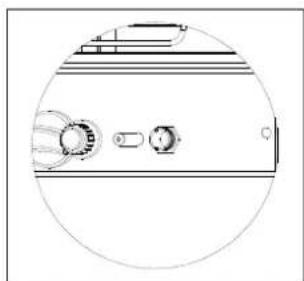
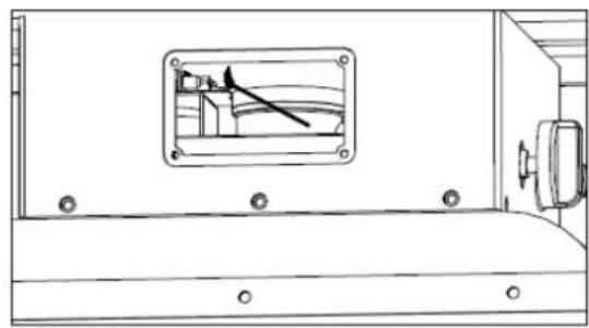
- Pilot flame can be watched and checked from the square window with sliding lid(Figure 1&2) located at the bottom of the flame screen. The pilot also can be lighted by match.
Take off the sliding lid, through the window to light the pilot by match.
TO TURN OFF THE HEATER
-
Press and turn the variable control knob to OFF position.
-
Turn off the valve on the gas supply cylinder completely.
text_image
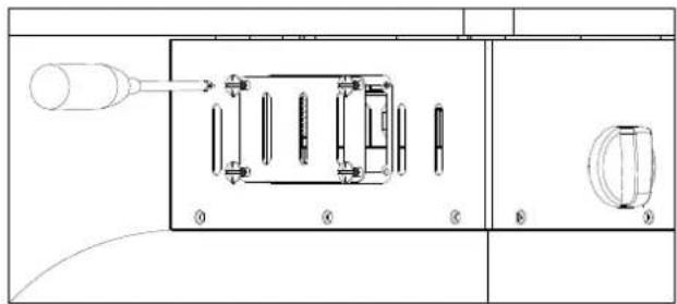
Technical diagram of a mechanical assembly with labeled components and directional arrows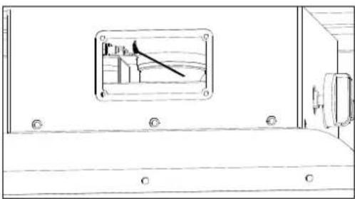
text_image
Technical diagram showing a mechanical assembly with labeled components and a magnified inset of a component.Figure1
Figure2
CLEANING AND MAINTENANCE:
● To enjoy outstanding performance of your heater for years make sure to perform the following maintenance activities on a regular basis:
- Keep exterior surfaces clean.
--Use warm soapy water for cleaning. Never use flammable, corrosive or abrasive cleaners.
--While washing your unit, be sure to keep the area around the burner and pilot assembly dry at all time. If the gas control is exposed to water in any way, do NOT try to use it. It must be replaced.
● After a long break from operation, the unit should be inspected for spiders, spider webs or other insects
● Air flow must be unobstructed. Keep controls. Burner and circulating air passageways clean. Signs of possible blockage include:
--Gas dour with extreme yellow tipping of flame.
--Heater does NOT reach the desired temperature.
--Heater glow is excessively uneven.
--Heater makes popping noises.
● Spider and insects can nest in burner or orifices. This dangerous condition can damage heater and render it unsafe for use. Clean burner holes by using a heavy-duty pipe cleaner. Compressed air may help clear away smaller particles.
- Carbon deposits may create a fire hazard. Clean reflector and glass tube inside with soapy water if any carbon develops. Always be careful when cleaning the glass tube.
STORAGE:
Between uses:
- Turn the control knob to "OFF" position.
- Turn LPG cylinder to "OFF" position.
● Store heater upright in an area sheltered away foam weather conditions (such as rain, sleet, hail, snow) - If desired, cover heater to protect exterior surfaces and to help prevent dust and debris collecting in air passages.
During periods of extended inactivity or when transporting:
- Turn the control to "OFF" position.
- Disconnect LPG cylinder and move to a secure, well-ventilated location outdoors. DO NOT store in a location that will exceed 50 degrees C.
● Store heater upright in an area sheltered away from weather conditions (such as rain, sleet, hail, snow) - If desired, cover heater to protect exterior surfaces and to help prevent dust and debris collecting in air passages.
| WARNINGFOR YOUR SAFETYDO NOT touch or move heater for at least 45 minutes after use.Allow all burner elements to cool before Touching | NOTEIn a salt-air environment (such as near an Ocean) corrosion occurs more quickly than normalFrequently check for corroded areas and Repair them promptly.Wait until heater is cool before covering. |
natural_image
Technical line drawing of a vertical industrial or thermal tower with heat exchangers and control panel (no text or symbols)| Part No. | Part Name | QTY |
| A | Reflector | 1 |
| B | Upper plate | 1 |
| C | Glass tube | 1 |
| D | Burner assembly | 1 |
| E | Tank | 1 |
| F | Wheel | 1 |
PARTS LIST-2
| Part No. | Part Name | QTY | Picture | Remarks |
| 1 | Bolt M8 | 2 |  | |
| 2 | Nut M8 | 2 |  | |
| 3 | Bolt M5 | 8 |  | |
| 4 | Nut M5 | 12 |  | |
| 5 | Washer Φ6 | 6 |  | |
| 6 | Wrench | 1 | 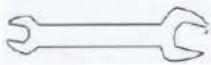 | |
| 7 | Reflector support | 3 | 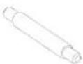 | |
| 8 | Wing nut M6 | 3 |  | |
| 9 | Rubber ring | 1 | 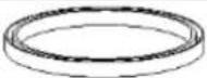 | |
| 10 | Wrench 8mm | 1 |  |
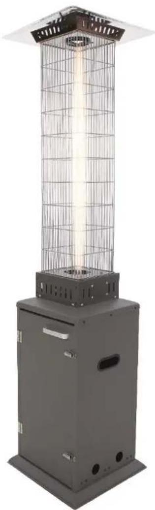
Construction and characteristics:
- Transportable terrace/garden heater with tank housing
• Stainless steel flame screen - heat emission from reflector
B. Specifications
For outdoor use only
Weight: 28Kgs
Height: 2150mm
Countries of destination, pressure.
| APPLIANCE CATEGORY: | I_3+(28-30/37) | I_3B/P(30) | I_3B/P(50) | I_3B/P(37) | |
| TYPES OF GAS: | Butane | Propane | Butane, propane or their mixtures | Butane, propane or their mixtures | Butane, propane or their mixtures |
| GAS PRESSURE: | 28-30mbar | 37 mbar | 30 mbar | 50mbar | 37mbar |
| OUTLET PRESSURE OF REGULATOR: | 30mbar | 37 mbar | 30 mbar | 50mbar | 37mbar |
● Using the proper regulator according to outlet pressure of regulator as showed in the table above.
C. Table of injector
| APPLIANCE CATEGORY: | I_3+(28-30/37) | I_3B/P(30) | I_3B/P(50) | I_3B/P(37) | |
| TYPES OF GAS: | Butane | Propane | Butane, propaneor their mixtures | Butane, propaneor their mixtures | Butane, propaneor their mixtures |
| GAS PRESSURE: | 28-30mbar | 37 mbar | 30 mbar | 50mbar | 37mbar |
| TOTAL HEATINPUT (Hs): (Qn) | 11KW(800g/h) | ||||
| INJECTOR SIZE: | 1.6 mm for main burner0.18 mm for pilot burner | 1.4 mm for main burner0.18 mm for pilot burner | 1.5 mm for main burner0.18 mm for pilot burner | ||
| The marking, for example, 1.6 on the injector, indicates that the size of injector is 1.6 mm | |||||
● The hose and regulator assembly must conform to local standard codes.
● Regulator outlet pressure should meet the corresponding appliance category in B. Specification.
General components & features
Familiarize yourself with all components before proceeding. Refer to page 4 for Hardware and Components, and page 5 for specifications.
Do NOT attempt to assemble unless all components are available. If you believe a component is missing or damaged, contact customer service for assistance.
Note: All hardware is mounted on a cardboard pack.
Additional Requirements
The following items are not included, but are necessary for the proper assembly of your heater. Do NOT attempt to assemble without proper tools. An open end wrench (10 & 13mm) is necessary and is included in the parts bag.
Tools needed:
- Adjustable opening wrench (20cm /8" long)
- Slip joint pilers (23cm/9" long)
● Philips screw-driver w/ medium blade - Teflon plumbing tape for joints
- Spray bottle of soap solution for leakage test
Finished
The installation must conform with local building codes, or in absence of local codes,
HEATER ASSEMBLY
1 Phillips head screwdriver, 1 adjustable spanner
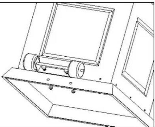 | 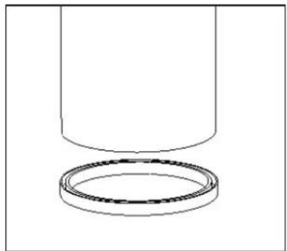 |
| 1.Assemble wheel(M) to the base, insert M8(1) and tighten M8 nut(2) | 2. Assemble the rubber ring to one end of glass tube |
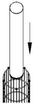 | 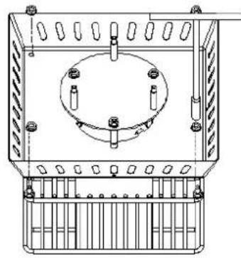 |
| Put the end with rubber ring to burner assembly and assemble the glass tube | 4 Connect the tube(F) to the burner assembly by 8 screws 3/16"(3) and tighten all screws |
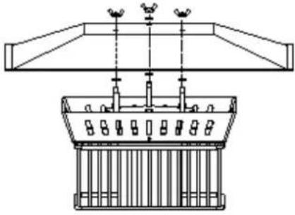 | 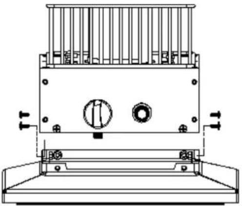 |
| 5 Screw and tighten the reflector (A), put on the washer(5) and assemble the reflector(A) by wing nuts(9). | 3.Connect Burner assembly to the tank by 8 screws(7) and 8 nuts M5(4) |
Caution:
The connections on this outdoor Heater has been checked at the factory for leaks. Recheck all connections, as movement in shipping can loosen connections. Check for leaks even if your unit was assembled for you at the store.
WARNING
- The whole gas system, hose, regulator, or burner should be inspected for leak before each use.
- Check the hose assembly for sign of extreme abrasion, cuts or wear. Suspected areas should be leak tested.
- Make sure the ventilation opening of the cylinder enclosure, control compartment, burner and circulation air passageways of the heater are free and clear of debris. If debris, spider or insect nests are found, clean the holes with heavy duty pipe cleaner or compressed air.
- Always keep a dry chemical fire extinguisher readily available. For safety, always allow a 5-minute complete shut off period before re-lighting a hot heater.
- Do not move the heater, or cover it with protective cover after it has been turned off until the temperature has completely cooled down.
Troubleshooting
| PROBLEMS | PROBABLE CAUSES | SOLUTIONS |
| Pilot will not light | Gas valve may be OFF | Turn the gas valve ON |
| Tank fuel empty | Refill LPG tank | |
| Opening blocked | Clean or replace opening | |
| Air in supply system | Purge air from lines | |
| Loose connection | Check all fittings | |
| Pilot will not stay on | Debris around pilot | Clean dirty area |
| Loose connection | Tighten connection | |
| Thermocouple bad | Replace Thermocouple | |
| Gas leak in line | Check connections | |
| Lack of fuel pressure | LPG cylinder is near empty | |
| Burner will not light | Gas pressure is low | LPG cylinder is near empty |
| Orifice blocked | Remove, clean and replace | |
| Control not on | Turn valve to ON | |
| Thermocouple bad | Replace Thermocouple | |
| Pilot light assembly bent or not in correct location | Place pilot light in correct position and retry |
● Any repairs to the patio heater must be carried out by a qualified person
Handleiding Flame Torch (NL)
natural_image
Exterior view of a tall outdoor heating tower with visible heat source and grid structure (no text or symbols)natural_image
Simple line drawing of a lamp inside a transparent cube (no text or symbols)Waarschuwing:
natural_image
Technical line drawing of a mechanical assembly with internal components and no visible text or symbolsBRANDSTOF GAS GEUR
natural_image
Technical line drawing of a mechanical component with circular features and no visible text or symbolsDE KACHEL DRAAIEN
text_image
Pilot 4 Low Hi offLet op:
natural_image
Technical line drawing of a mechanical device with ports and components (no text or symbols)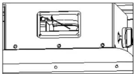
natural_image
Technical line drawing of a mechanical assembly or enclosure with mounting holes and internal components (no text or symbols)REINIGING EN ONDERHOUD:
| APPLIANCE CATEGORY: | I_3+(28-30/37) | I_3B/P(30) | I_3B/P(50) | I_3B/P(37) | |
| TYPES OF GAS: | Butane | Propane | Butane, propane or their mixtures | Butane, propane or their mixtures | Butane, propane or their mixtures |
| GAS PRESSURE: | 28-30mbar | 37 mbar | 30 mbar | 50mbar | 37mbar |
| OUTLET PRESSURE OF REGULATOR: | 30mbar | 37 mbar | 30 mbar | 50mbar | 37mbar |
● Using the proper regulator according to outlet pressure of regulator as showed in the table above.
C. Table of injector
| APPLIANCE CATEGORY: | I_3+(28-30/37) | I_3B/P(30) | I_3B/P(50) | I_3B/P(37) | |
| TYPES OF GAS: | Butane | Propane | Butane, propane or their mixtures | Butane, propane or their mixtures | Butane, propane or their mixtures |
| GAS PRESSURE: | 28-30mbar | 37 mbar | 30 mbar | 50mbar | 37mbar |
| TOTAL HEAT INPUT (Hs): (Qn) | 11KW(800g/h) | ||||
| INJECTOR SIZE: | 1.6 mm for main burner0.18 mm for pilot burner | 1.4 mm for main burner0.18 mm for pilot burner | 1.5 mm for main burner0.18 mm for pilot burner | ||
| The marking, for example, 1.16 on the injector, indicates that the size of injector is 1.6 mm | |||||
● The hose and regulator assembly must conform to local standard codes.
● Regulator outlet pressure should meet the corresponding appliance category in B. Specification.
natural_image
Line drawing of a mechanical device with a cylindrical component mounted on a base (no text or symbols)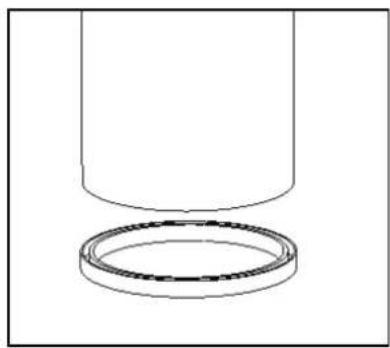
natural_image
Simple line drawing of a cylindrical object with a separate ring, no text or symbols presentnatural_image
Technical line drawing of a mechanical component with internal circular housing and mounting holes (no text or symbols)natural_image
Technical line drawing of a mechanical assembly with supports and components (no text or symbols)natural_image
Technical line drawing of a mechanical device with no visible text or symbolsnatural_image
Exterior view of a tall outdoor heating tower with grid structure and ventilation grilles (no text or symbols visible)natural_image
Simple line drawing of a lamp inside a transparent cube (no text or symbols)Warnung:
natural_image
Technical line drawing of a mechanical assembly with internal components and no visible text or symbolsnatural_image
Circular diagram showing a device with multiple ports and a central control knob (no text or symbols)text_image
Pilot4 Low off Hinatural_image
Technical line drawing of a mechanical assembly with no visible text or symbolsAbb. 1
natural_image
Technical line drawing of a mechanical assembly with a central component and mounting holes (no text or symbols)Abb.2
natural_image
Exterior view of a portable outdoor heating tower with vertical metal frame and central heat sink (no text or symbols visible)natural_image
Simple line drawing of a lamp inside a transparent cube (no text or symbols)Mise en garde :
natural_image
Technical line drawing of a mechanical assembly with internal components and no visible text or symbolsCARBURANT ODEUR GAZ
INSTRUCTIONS D'ALLUMAGE
natural_image
Pure diagram of a circular mechanical component with no text, numbers, or symbolstext_image
Pilot 4 Low Hi offVeuillez noter :
| APPLIANCE CATEGORY: | I_3+(28-30/37) | I_3B/P(30) | I_3B/P(50) | I_3B/P(37) | |
| TYPES OF GAS: | Butane | Propane | Butane, propane or their mixtures | Butane, propane or their mixtures | Butane, propane or their mixtures |
| GAS PRESSURE: | 28-30mbar | 37 mbar | 30 mbar | 50mbar | 37mbar |
| OUTLET PRESSURE OF REGULATOR: | 30mbar | 37 mbar | 30 mbar | 50mbar | 37mbar |
● Using the proper regulator according to outlet pressure of regulator as showed in the table above.
C. Table of injector
| APPLIANCE CATEGORY: | I_3+(28-30/37) | I_3B/P(30) | I_3B/P(50) | I_3B/P(37) | |
| TYPES OF GAS: | Butane | Propane | Butane, propaneor their mixtures | Butane, propaneor their mixtures | Butane, propaneor their mixtures |
| GAS PRESSURE: | 28-30mbar | 37 mbar | 30 mbar | 50mbar | 37mbar |
| TOTAL HEATINPUT (Hs): (Qn) | 11KW(800g/h) | ||||
| INJECTOR SIZE: | 1.6 mm for main burner0.18 mm for pilot burner | 1.4 mm for main burner0.18 mm for pilot burner | 1.5 mm for main burner0.15 mm for pilot burner | ||
| The marking, for example, 1.i 6 on the injector, indicates that the size of injector is 1.6 mm | |||||
● The hose and regulator assembly must conform to local standard codes.
● Regulator outlet pressure should meet the corresponding appliance category in B. Specification.
Manual Square Flame Torch (UK)
Handleiding Flame Torch (NL)