AVH-X8800BT - Car stereo PIONEER - Free user manual and instructions
Find the device manual for free AVH-X8800BT PIONEER in PDF.


User questions about AVH-X8800BT PIONEER
0 question about this device. Answer the ones you know or ask your own.
Ask a new question about this device
Download the instructions for your Car stereo in PDF format for free! Find your manual AVH-X8800BT - PIONEER and take your electronic device back in hand. On this page are published all the documents necessary for the use of your device. AVH-X8800BT by PIONEER.
USER MANUAL AVH-X8800BT PIONEER
Your new product and this manual
- Do not operate this product, any applications, or the rear view camera option (if purchased) if doing so will divert your attention in any way from the safe operation of your vehicle. Always observe safe driving rules and follow all existing traffic regulations. If you experience difficulty in operating this product or reading the display, park your vehicle in a safe location and apply the handbrake before making the necessary adjustments.
- Do not install this product where it may
(i) obstruct the driver's vision,
(ii) impair the performance of any of the vehicle's operating systems of safety features, including airbags, hazard lamp buttons, or
(iii) impair the driver's ability to safely operate the vehicle. In some cases, it may not be possible to install this product because of the vehicle type or the shape of the vehicle interior.
The graphical symbol placed on the product means direct current.
Important safeguards
CAUTION
Pioneer does not recommend that you install this product yourself. This product is designed for professional installation only. We recommend that only authorised Pioneer service personnel, who have special training and experience in mobile electronics, set up and install this product. NEVER SERVICE THIS PRODUCT YOURSELF. Installing or servicing this product and its connecting cables may expose you to the risk of electric shock or other hazards, and can cause damage to this product that is not covered by warranty.
Precautions before connecting the system
WARNING
Do not take any steps to tamper with or disable the handbrake interlock system which is in place for your protection. Tampering with or disabling the handbrake interlock system could result in serious injury or death.
CAUTION
- Secure all wiring with cable clamps or electrical tape. Do not allow any bare wiring to remain exposed.
- Do not directly connect the yellow lead of this product to the vehicle battery. If the lead is directly connected to the battery, engine vibration may eventually cause the insulation to fail at the point where the wire passes from the passenger compartment into the engine compartment. If the yellow lead's insulation tears as a result of contact with metal parts, short-circuiting can occur, resulting in considerable danger.
- It is extremely dangerous to allow cables to become wound around the steering column or gearstick. Be sure to install this product, its cables, and wiring away in such so that they will not obstruct or hinder driving.
- Make sure that the cables and wires will not interfere with or become caught in any of the vehicle's moving parts, especially the steering wheel, gearstick, handbrake, sliding seat tracks, doors, or any of the vehicle's controls.
- Do not route wires where they will be exposed to high temperatures. If the insulation heats up, wires may become damaged, resulting in a short circuit or malfunction and permanent damage to the product.
- Do not shorten any leads. If you do, the protection circuit (fuse holder, fuse resistor or filter, etc.) may fail to work properly.
- Never feed power to other electronic products by cutting the insulation of the power supply lead of this product and tapping into the lead. The current capacity of the lead will be exceeded, causing overheating.
Before installing this product
- Use this product with a 12-volt battery and negative grounding only. Failure to do so may result in a fire or malfunction.
- To avoid shorts in the electrical system, be sure to disconnect the (-) battery cable before installation.
To prevent damage
WARNING
Use speakers over 50 W (maximum input power) and between 4 Ω to 8 Ω (impedance value). Do not use 1 Ω to 3 Ω speakers for this product.
The black lead is earth. Please earth this lead separately
from the earth of high-current products such as power amps. Do not earth more than one product together with the earth from another product. For example, you must separately earth any amp unit away from the earth of this product. Connecting grounds together can cause a fire and/or damage the products if their grounds became detached.
- When replacing the fuse, be sure to only use a fuse of the rating prescribed on this product.
This product cannot be installed in a vehicle without ACC (accessory) position on the ignition switch.
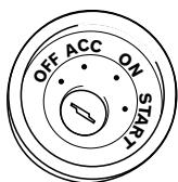
ACC position
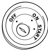
No ACC position
- To avoid short-circuiting, cover the disconnected lead with insulating tape. It is especially important to insulate all unused speaker leads, which if left uncovered may cause a short circuit.
- For connecting a power amp or other devices to this product, refer to the manual for the product to be connected.
Notice for the blue/white lead
When the ignition switch is turned on (ACC ON), a control signal is output through the blue/white lead. Connect to an external power amp's system remote control terminal, the auto-aerial relay control terminal, or the aerial booster power control terminal (max. 300 mA 12 V DC). The control signal is output through the blue/white lead, even if the audio source is switched off.
Important
When this product is in "Power OFF" mode, the control signal is also turned off. If "Power OFF" mode is cancelled, the control signal is output again and the aerial is extended with the auto aerial function (if the aerial is being used). Be careful so that the extended aerial does not come into contact with any obstacles.
Connection
Rear panel (main terminals)
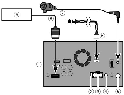
① This product
② Fuse(10A)
③ Power supply
④ Wired remote input Hard-wired remote control adapter can be connected (sold separately).
⑤ Aerial jack
Vehicle Bus conversion cable 15.8 cm Please refer to the instruction manual for the Vehicle Bus adapter (sold separately).
⑦ Microphone 3m
RGB cable (supplied with Navigation system)
9 Pioneer navigation system Please contact your dealer to inquire about the connectable navigation unit.
Power cord
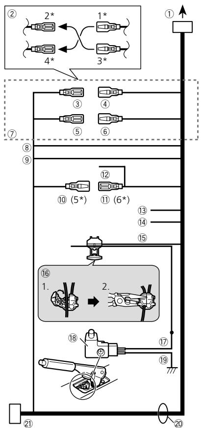
① To power supply
② Depending on the kind of vehicle, the function of 2^ and 4^ may be different. In this case, be sure to connect 1^ to 4^ and 3^ to 2^
③ Yellow (2^)
Back-up (or accessory)
④ Yellow (1)
Connect to the constant 12 V supply terminal.
⑤ Red (4^*)
Accessory (or back-up)
⑥ Red (3^*)
Connect to terminal controlled by ignition switch (12 V DC).
⑦ Connect leads of the same colour to each other.
⑧ Orange/white
To lighting switch terminal.
⑨ Black (ground)
To vehicle (metal) body.
10 Blue/white (5*)
The pin position of the ISO connector will differ depending on the type of vehicle. Connect 5^ and 6^ when Pin 5 is an aerial control type. In another type of vehicle, never connect 5^ and 6^ .
1 Blue/white (6^*)
Connect to auto-aerial relay control terminal (max. 300mA 12 V DC).
12 Blue/white
Connect to system control terminal of the power amp (max. 300mA12VDC
Violet/white
Of the two lead wires connected to the back lamp, connect the one in which the voltage changes when the gear shift is in the REVERSE (R) position. This connection enables the unit to sense whether the car is moving forwards or backwards.
14 Yellow/black
If you use an equipment with Mute function, wire this lead to the Audio Mute lead on that equipment. If not, keep the Audio Mute lead free of any connections.
15 Light green
Used to detect the ON/OFF status of the handbrake. This lead must be connected to the power supply side of the handbrake switch.
2 Clamp firmly with needle-nosed pliers.
16 Connection method
1 Clamp the lead.
17 Power supply side
Handbrake switch
Earth side
20 Speaker leads
White: Front left +
White/black: Front left -
Connection
Grey:Front right ^+
Grey/black: Front right -
Green: Rear left +
Green/black:Rear left
Violet:Rear right ^+
Violet/black: Rear right -
ISO connector
In some vehicles, the ISO connector may be divided into two. In this case, be sure to connect to both connectors.
The position of the handbrake switch depends on the vehicle model. For details, consult the vehicle Owner's Manual or dealer.
Power amp (sold separately)
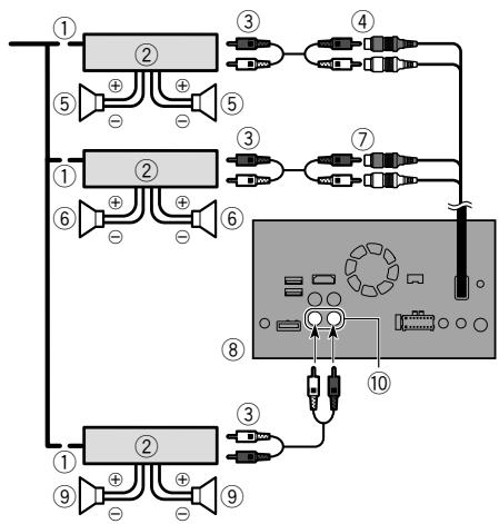
① System remote control
Connect to Blue/white cable (max. 300 mA 12 V DC).
② Power amp (sold separately)
③ Connect with RCA cable (sold separately)
④ Rear outputs (REAR OUTPUT) 15 cm
⑤ Rear speaker
⑥ Front speaker
⑦ Front outputs (FRONT OUTPUT) 15 cm
This product
⑨ Subwoofer
Subwoofer outputs
- You can change the RCA output of the subwoofer depending on your subwoofer system.
Refer to the operation manual.
The subwoofer output of this product is monaural.
Connection
Connecting an iPod / iPhone or an Android device
Find your device and the function you want to operate from the list below, and refer to the page for the connection.
Depending on the device, some functions may not be available.
| iPhone (5, 5c, 5s, 6, 6 Plus)/iPod touch (5th generation) | |
| iPod (audio) Apple CarPlay | Refer to Connecting via the USB port (iPhone) on page 6 |
| AppRadio Mode | Refer to Connecting via the HDMI port (iPhone) on page 6 |
| iPhone 3GS/iPod touch (2nd, 3rd generation)/iPod classic (80GB, 160GB)/iPod nano (3rd, 4th, 5th, 6th generation) | |
| iPod (audio) iPod (video) | Refer to Connecting via the AUX input (iPhone) on page 6 |
| iPhone (4, 4s)/iPod touch (4th generation) | |
| iPod (audio) iPod (video) AppRadio Mode | Refer to Connecting via the RGB input (iPhone) on page 7 |
| iPod nano (7th generation) | |
| iPod (audio) | Refer to Connecting via the USB port (iPhone) on page 6 |
| Android device | |
| AppRadio Mode | HDMI port Refer to Connecting via the HDMI port (Android device) on page 7 |
| MHL port Refer to Connecting via the MHL port (Android device) on page 7 | |
| Android Auto | Refer to Connecting via the USB port (Android device) on page 7 |
Connection
iPhone and smartphone
For details on how to connect an external device using a separately sold cable, refer to the manual for the cable.
For details concerning the connection, operations and compatibility of iPhone, refer to Operation Manual.
For details concerning the connection and operations of Android device, refer to Operation Manual.
In this chapter, iPhone and iPod touch will be referred to as "iPhone".
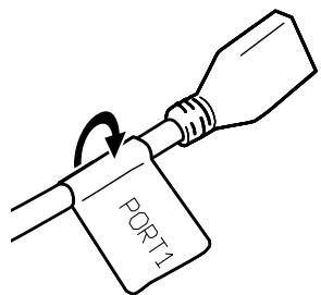
Attaching identification labels to USB cables
Attach identification labels to USB cables before installing this product in a vehicle.
1 Connect USB cables to the USB port 1 and 2 on the rear of this product.
2 Attach the identification labels corresponding to each port to the USB cables as illustrated below.
Attach the "PORT 1" label to the USB cable connected to the USB port 1.
Attach the "PORT 2" label to the USB cable connected to the USB port 2.
iPhone with Lightning connector
Connecting via the USB port (iPhone)
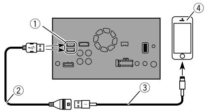
① USB port 1/USB port 2
② USB cable 1.5 m
③ USB interface cable for iPod / iPhone (CD-IU52) (sold separately)
- When using Apple CarPlay, connect the iPhone to USB port 1.
④ iPhone with Lightning connector
Connecting via the HDMI port (iPhone)
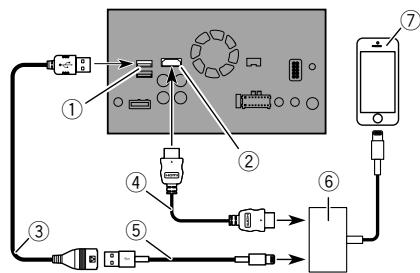
① USB port 1
② HDMI port
③ USB cable 1.5 m
High Speed HDMI Cable (Type A - A) (supplied with CD-IH202)
⑤ USB interface cable for iPod / iPhone (CD-IU52) (sold separately)
Lightning Digital AV Adapter (Apple Inc. products) (sold separately)
⑦ iPhone with Lightning connector
- When you connect the High Speed HDMI® Cable, use the lock tie to fix it securely.
Refer to Securing the High Speed HDM/Cable on page 7
iPhone with 30-pin connector
Connecting via the AUX input (iPhone)
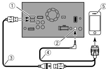
① USB port 1/USB port 2
② AUX input
③ USB cable 1.5 m
④ USB interface cable for iPod / iPhone (CD-IU201V) (sold separately)
⑤ iPhone with 30-pin connector
Connection
Connecting via the RGB input (iPhone)
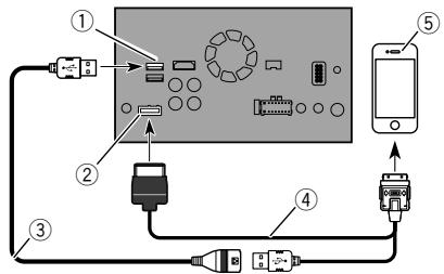
① USB port 1
② RGB input
③ USB cable 1.5 m
④ USB interface cable for iPod / iPhone (CD-IU201S) (sold separately)
⑤ iPhone with 30-pin connector
Android device
Connecting via the HDMI port (Android device)
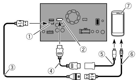
① USB port 2
② HDMI port
③ USB cable 1.5 m
④ High Speed HDMI® Cable (Type A - A) (supplied with CD-AH200)
⑤ Adapter cable (HDMI Type A - D) (supplied with CD-AH200)
⑥ USB - micro USB cable (Type USB A - micro USB B) (supplied with CD-AH200)
⑦ Android device
- When you connect the High Speed HDMI® Cable, use the lock tie to fix it securely.
Refer to Securing the High Speed HDMI® Cable on page 7
Connecting via the MHL port (Android device)

① USB port 2
② HDMI port
③ USB cable 1.5 m
^4 High Speed HDMI® Cable (Type A - A) (supplied with CD-AH200)
⑤ MHL adapter (supplied with CD-AH200)
⑥ Android device
- When you connect the High Speed HDMI® Cable, use the lock tie to fix it securely.
Refer to Securing the High Speed HDMI Cable on page 7
Connecting via the USB port (Android device)
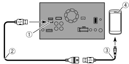
① USB port 2
② USB cable 1.5 m
③ USB - micro USB cable (Type USB A - micro USB B) (supplied with CD-MU200)
④ Android device
For details on how to connect an external device using a separately sold cable, refer to the manual for the cable.
Securing the High Speed HDMI® Cable
Be sure to fix the High Speed HDMI® Cable with the lock tie, when you connect the external device with the High Speed HDMI® Cable.
1 Insert the High Speed HDMI® Cable into the HDMI port.
2 Wrap the lock tie around the hook above the HDMI port and the High Speed HDMI® Cable, and then tighten it to secure the High Speed HDMI® Cable.
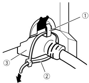
Connection
① Hook
② Lock tie
③ High Speed HDMI® Cable
CAUTION
Do not tighten up the lock tie more than necessary.
Camera
When you use the rear view camera, the rear view image is automatically switched from the video by moving the gearstick to REVERSE (R). Camera View mode also allows you to check what is behind you while driving.
WARNING
USE INPUT ONLY FOR REVERSE OR MIRROR IMAGE REAR VIEW CAMERA. OTHER USE MAY RESULT IN INJURY OR DAMAGE.
CAUTION
The screen image may appear reversed.
- With the rear view camera you can keep an eye on trailers, or back into a tight parking spot. Do not use for entertainment purposes.
- Objects in rear view may appear closer or more distant than in reality.
- The image area of full-screen images displayed while backing or checking the rear of the vehicle may differ slightly.
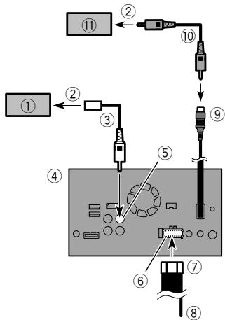
① Rear view camera (ND-BC8) (sold separately)
② To video output
③ RCA cable (supplied with ND-BC8)
④ This product
⑤ Brown (BC IN)
⑥ Power supply
⑦ Power cord
⑧ Violet/white (REVERSE-GEAR SIGNAL INPUT)
Refer to Power cord on page 3
9 Yellow (VIDEO INPUT) 15 cm
10 RCA cable (sold separately)
View camera (sold separately)
- Connect only the rear view camera to BC IN. Do not connect any other equipment.
Some appropriate settings are required to use other view cameras.
Refer to the operation manual.
External video component
Using AV input
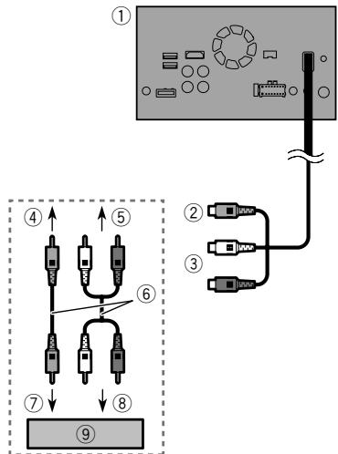
① This product
② Yellow (VIDEO INPUT) 15 cm
③ Red, white (AUDIO INPUT) 23 cm
④ To Yellow
⑤ To Red, white
⑥ RCA cables (sold separately)
⑦ To video output
⑧ To audio outputs
External video component (sold separately)
The appropriate setting is required to use the external video component.
Refer to the operation manual.
Connection
Using an AUX input
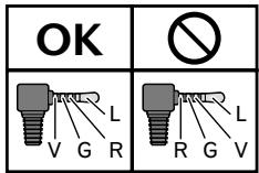
L:Left audio (White)
R:Rightaudio(Red)
V : Video (Yellow)
G:Ground
Using an HDMI input
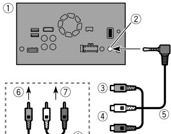
① This product
② AUXinput
③ Yellow
④ Red, white
⑤ Mini-jack AV cable (CD-RM10) (sold separately)
⑥ To Yellow
⑦ To Red, white
⑧ RCA cables (sold separately)
⑨ To video output
To audio outputs
1 External video component (sold separately)
The appropriate setting is required to use the external video component.
Refer to the operation manual.
- When connecting an external video component using a mini-jack AV cable, use a separately sold AUX extension cable as necessary.
CAUTION
Be sure to use a mini-jack AV cable (CD-RM10) (sold separately) for wiring. If you use other cables, the wiring position might differ resulting in disturbed images and sounds.
Rear display
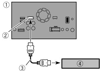
① This product
② HDMI port
③ High Speed HDMI® Cable (sold separately)
④ HDMI device (sold separately)
- When you connect the High Speed HDMI® Cable, use the lock tie to fix it securely.
Refer to Securing the High Speed HDMI Cable on page 7
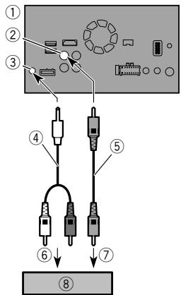
① This product
② Yellow(VOUT)
③ Rear audio output
④ Mini pin plug cable (sold separately)
⑤ RCA cables (sold separately)
⑥ To audio inputs
⑦ To video input
Rear display with RCA input jacks (sold separately)
WARNING
NEVER install the rear display in a location that enables the driver to watch video images while driving.
This product's rear video output is for connection of a display to enable passengers in the rear seats to watch the video source.
Installation
Precautions before installation
CAUTION
Never install this product in places where, or in a manner that:
- Could injure the driver or passengers if the vehicle stops suddenly.
- May interfere with the driver's operation of the vehicle, such as on the floor in front of the driver's seat, or close to the steering wheel or gearstick.
To ensure proper installation, be sure to use the supplied parts in the manner specified. If any parts are not supplied with this product, use compatible parts in the manner specified after you have the parts' compatibility checked by your dealer. If parts other than supplied or compatible ones are used, they may damage internal parts of this product or they may work loose and the product may become detached. - Do not install this product where it may (i) obstruct the driver's vision, (ii) impair the performance of any of the vehicle's operating systems or safety features, including airbags, hazard lamp buttons or (iii) impair the driver's ability to safely operate the vehicle.
- Never install this product in front of or next to the place in the dashboard, door, or pillar from which one of your vehicle's airbags would deploy. Please refer to your vehicle's owner's manual for reference to the deployment area of the frontal airbags.
Before installing
- Consult with your nearest dealer if installation requires drilling holes or other modifications of the vehicle.
Before making a final installation of this product, temporarily connect the wiring to confirm that the connections are correct and the system works properly. - Do not install this product in a position where the opening of the LCD panel is obstructed by any obstacles, such as the gearstick. Before installing this product, be sure to leave sufficient space so that the LCD panel does not obstruct the gearstick when it is fully opened. This may cause interference with the gearstick, or a malfunction of the mechanism of this product.
Installation notes
-
Do not install this product in places subject to high temperatures or humidity, such as:
-
Places close to a heater, vent or air conditioner.
- Places exposed to direct sunlight, such as on top of the dashboard.
- Places that may be exposed to rain, such as close to the door or on the vehicle's floor.
- Install this product horizontally on a surface within 0 to 30 degrees tolerance (within 5 degrees to the left or right). Improper installation of the product with the surface tilted more than these tolerances increases the potential for errors in the vehicle's location display, and might otherwise cause reduced display performance.
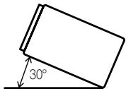
- When installing, to ensure proper heat dispersal when using this product, make sure you leave ample space behind the rear panel and wrap any loose cables so they are not blocking the vents.

Before installing this product
1 Remove the trim ring.
Extend top and bottom of the trim ring outwards to remove the trim ring.
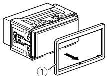
① Trim ring
2 Insert the supplied extraction keys into both sides of the unit until they click into place.
3 Pull the unit out of the holder.
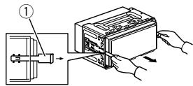
① Extraction key
Installation with the holder
1 Install the holder into the dashboard.
2 Secure the mounting sleeve by using a screwdriver to bend the metal tabs (90^) into place.
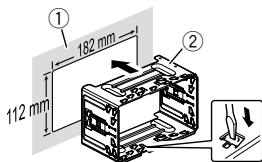
① Dashboard
② Holder
3 Install this product into the holder.
Installation
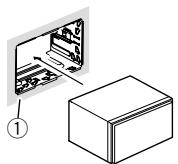
① Dashboard
4 Attach the trim ring.
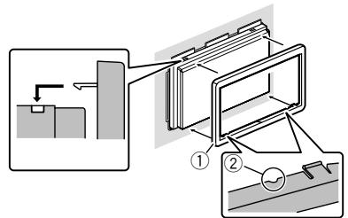
① Trim ring
② Groove
Attach the trim ring with the side with a groove facing downward.
Installation using the screw holes on the side of this product
1 Fastening this product to the factory radio-mounting bracket.
Position this product so that its screw holes are aligned with the screw holes of the bracket, and tighten the screws at three locations on each side.
Use either the truss head screws (5mm× 8mm) or flush surface screws (5mm× 9mm) , depending on the shape of the bracket's screw holes.
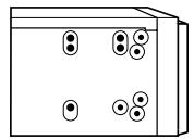
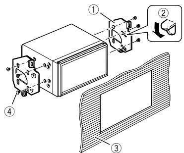
① Factory radio-mounting bracket
② If the pawl interferes with installation, you may bend it down out of the way.
③ Dashboard or console
④ Truss head screw or flush surface screw
Be sure to use the screws supplied with this product.
Installing the microphone
Install the microphone in a place where its direction and distance from the driver make it easiest to pick up the driver's voice.
- Be sure to turn off (ACC OFF) the product before connecting the microphone.
- Depending on the vehicle model, the microphone cable length may be too short when you mount the microphone on the sun visor. In such cases, install the microphone on the steering column.
Mounting on the sun visor
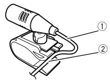
1 Fit the microphone lead into the groove.
① Microphone lead
② Groove
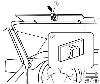
2 Attach the microphone clip to the sun visor.
① Microphone clip
② Clamps
Use separately sold clamps to secure the lead where necessary inside the vehicle.
Install the microphone on the sun visor when it is in the up position. It cannot recognise the driver's voice if the sun visor is in the down position.
Installation
Installation on the steering column
1 Detach the microphone base from the microphone clip by sliding the microphone base while pressing the tab.
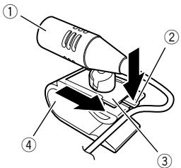
① Microphone
② Tab
③ Microphone base
④ Microphone clip
2 Mount the microphone on the steering column.
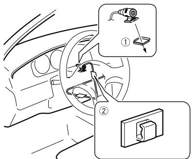
① Double-sided tape
Install the microphone on the steering column, keeping it away from the steering wheel.
② Clamps
Use separately sold clamps to secure the lead where necessary inside the vehicle.
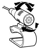
Adjusting the microphone angle
The microphone angle can be adjusted.
Precautions
L:Left audio (White)
R:Rightaudio(Red)
V : Video (Yellow)
G:Ground
L:Left audio (White)
R:Rightaudio(Red)
V : Video (Yellow)
G:Ground
L:Left audio (White)
R:Rightaudio(Red)
V : Video (Yellow)
G:Ground
L:Left audio (White)
R:Rightaudio(Red)
V : Video (Yellow)
G:Ground
① D it product
② Zekering (10 A)
③ Voeding
Accessoire (of back-up)
⑥ Rood (3^*)
L:Left audio (White)
R:Rightaudio(Red)
V : Video (Yellow)
G:Ground
PIONEER ELECTRONICS (USA) INC.
P.O. Box 1540, Long Beach, California 90801-1540, U.S.A.
TEL: (800) 421-1404
PIONEER ELECTRONICS OF CANADA, INC.
340 Ferrier Street, Unit 2, Markham, Ontario L3R 2Z5,
Canada
TEL: 1-877-283-5901
TEL: 905-479-4411
PIONEER EUROPE NV
Haven 1087, Keetberglaan 1, B-9120 Melsele, Belgium/
Belgique
TEL: (0) 3/570.05.11
PIONEER ELECTRONICS ASIACENTRE PTE. LTD.
2 Jalan Kilang Barat, #07-01, Singapore 159346
TEL: 65-6378-7888
PIONEER ELECTRONICS AUSTRALIA PTY. LTD.
5 Arco Lane, Heatherton, Victoria, 3202, Australia
TEL: (03) 9586-6300
PIONEER ELECTRONICS DE MEXICO S.A. DE C.V.
Blvd. Manuel Avila Camacho 138, 10 piso
Col.Lomas de Chapultepec, Mexico, D.F. 11000
Tel: 52-55-9178-4270, Fax: 52-55-5202-3714
先锋股份有限公司
台北市內湖區瑞光路407號8樓
電話:886-(0)2-2657-3588
先鋒電子(香港)有限公司
香港九龍長沙灣道909號5樓
電話:852-2848-6488