
Airdyne AD8 - Fitness Equipment Schwinn - Free user manual and instructions
Find the device manual for free Airdyne AD8 Schwinn in PDF.
| Product Type | Air Resistance Exercise Bike |
| Brand | Schwinn |
| Model | Airdyne AD8 |
| Dimensions (L x W x H) | 134.6 x 67.3 x 134.6 cm |
| Product Weight | 51.3 kg |
| Maximum User Weight | 159 kg |
| Power | 2 D batteries (LR20) or optional power adapter |
| Resistance | Air fan (progressive resistance based on effort) |
| Console | LCD display showing speed and program data, manual, interval, and target programs |
| Displays | Cal/min, Watts, RPM, speed, time, distance, calories, kJ, heart rate |
| Heart Rate | Compatible with non-coded Polar chest strap (4.5-5.5 kHz) |
| Workout Programs | Manual, 20/10 Interval, 30/90 Interval, Custom Interval, Time Target, Cal/kJ Target, MI/KM Target, Heart Rate Zones |
| Assembly | Requires 2 people, tools included |
| Warranty | Manufacturer warranty according to terms |
| Maintenance and Cleaning | Wipe after each use, clean console with soft cloth and mild dish soap |
| Safety | Emergency stop by slowing pedaling, come to a complete stop before dismounting, do not exceed maximum weight |
| Spare Parts and Repairability | Schwinn replacement parts, service by authorized technician |
| Usage | Household use only, on flat and stable surface |
| Electrical Specifications | Optional power adapter: 100-240V (not included) |
Frequently Asked Questions - Airdyne AD8 Schwinn
User questions about Airdyne AD8 Schwinn
0 question about this device. Answer the ones you know or ask your own.
Ask a new question about this device
Download the instructions for your Fitness Equipment in PDF format for free! Find your manual Airdyne AD8 - Schwinn and take your electronic device back in hand. On this page are published all the documents necessary for the use of your device. Airdyne AD8 by Schwinn.
USER MANUAL Airdyne AD8 Schwinn
Thanks for choosing SCHWINN Airdyne AD8 as your fitness equipment. We are sincerely encourage you to read through this Owner's manual carefully before the assembling of your equipment started, especially of below WARNINGS! WARNINGS WILL REDUCE THE RISK OF BURNS, FIRE, ELECTRICAL SHOCK OR INJURY TO PERSONS.
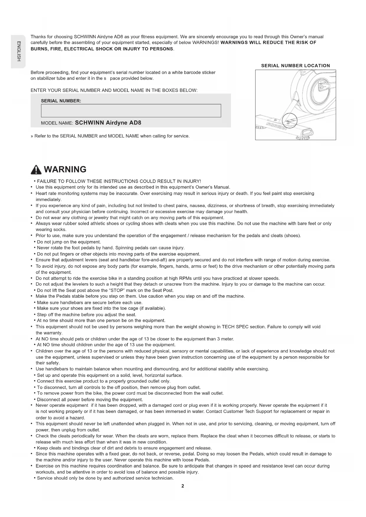
Before proceeding, find your equipment's serial number located on a white barcode sticker on stabilizer tube and enter it in the space provided below.
ENTER YOUR SERIAL NUMBER AND MODEL NAME IN THE BOXES BELOW:
SERIAL NUMBER:
MODEL NAME: SCHWINN Airdyne AD8
» Refer to the SERIAL NUMBER and MODEL NAME when calling for service.
SERIAL NUMBER LOCATION
natural_image
Technical line drawing of a mechanical assembly with a magnified inset showing a small component (no text or symbols)
WARNING
- FAILURE TO FOLLOW THESE INSTRUCTIONS COULD RESULT IN INJURY!
- Use this equipment only for its intended use as described in this equipment's Owner's Manual.
- Heart rate monitoring systems may be inaccurate. Over exercising may result in serious injury or death. If you feel paint stop exercising immediately.
- If you experience any kind of pain, including but not limited to chest pains, nausea, dizziness, or shortness of breath, stop exercising immediately and consult your physician before continuing. Incorrect or excessive exercise may damage your health.
- Do not wear any clothing or jewelry that might catch on any moving parts of this equipment.
- Always wear rubber soled athletic shoes or cycling shoes with cleats when you use this machine. Do not use the machine with bare feet or only wearing socks.
- Prior to use, make sure you understand the operation of the engagement / release mechanism for the pedals and cleats (shoes).
- Do not jump on the equipment.
- Never rotate the foot pedals by hand. Spinning pedals can cause injury.
- Do not put fingers or other objects into moving parts of the exercise equipment.
- Ensure that adjustment levers (seat and handlebar fore-and-aft) are properly secured and do not interfere with range of motion during exercise.
- To avoid injury, do not expose any body parts (for example, fingers, hands, arms or feet) to the drive mechanism or other potentially moving parts of the equipment.
- Do not attempt to ride the exercise bike in a standing position at high RPMs until you have practiced at slower speeds.
- Do not adjust the levelers to such a height that they detach or unscrew from the machine. Injury to you or damage to the machine can occur.
- Do not lift the Seat post above the "STOP" mark on the Seat Post.
- Make the Pedals stable before you step on them. Use caution when you step on and off the machine.
- Make sure handlebars are secure before each use.
- Make sure your shoes are fixed into the toe cage (if available).
- Step off the machine before you adjust the seat.
- At no time should more than one person be on the equipment.
- This equipment should not be used by persons weighing more than the weight showing in TECH SPEC section. Failure to comply will void the warranty.
- At NO time should pets or children under the age of 13 be closer to the equipment than 3 meter.
- At NO time should children under the age of 13 use the equipment.
- Children over the age of 13 or the persons with reduced physical, sensory or mental capabilities, or lack of experience and knowledge should not use the equipment, unless supervised or unless they have been given instruction concerning use of the equipment by a person responsible for their safety.
- Use handlebars to maintain balance when mounting and dismounting, and for additional stability while exercising.
- Set up and operate this equipment on a solid, level, horizontal surface.
- Connect this exercise product to a properly grounded outlet only.
- To disconnect, turn all controls to the off position, then remove plug from outlet.
• To remove power from the bike, the power cord must be disconnected from the wall outlet. - Disconnect all power before moving the equipment.
- Never operate equipment if it has been dropped, with a damaged cord or plug even if it is working properly. Never operate the equipment if it is not working properly or if it has been damaged, or has been immersed in water. Contact Customer Tech Support for replacement or repair in order to avoid a hazard.
- This equipment should never be left unattended when plugged in. When not in use, and prior to servicing, cleaning, or moving equipment, turn off power, then unplug from outlet.
- Check the cleats periodically for wear. When the cleats are worn, replace them. Replace the cleat when it becomes difficult to release, or starts to release with much less effort than when it was in new condition.
- Keep cleats and bindings clear of dirt and debris to ensure engagement and release.
- Since this machine operates with a fixed gear, do not back, or reverse, pedal. Doing so may loosen the Pedals, which could result in damage to the machine and/or injury to the user. Never operate this machine with loose Pedals.
-
Exercise on this machine requires coordination and balance. Be sure to anticipate that changes in speed and resistance level can occur during workouts, and be attentive in order to avoid loss of balance and possible injury.
• Service should only be done by and authorized service technician. -
Do not remove the protected covers unless instructed by professional and your local dealer.
- Do not remove the console covers unless instructed by Customer Tech Support.
- Do not use other attachments that are not recommended by the manufacturer. Attachments may cause injury.
- Return the unit to a service center for examination and repair.
- To prevent electrical shock, never drop or insert any object into any opening.
- Do not operate where aerosol (spray) products are being used or when oxygen is being administered.
- This equipment is intended for in-home use only. Failure to comply will void the warranty.
- Do not use equipment in any location that is not temperature controlled, such as but not limited to garages, porches, pool rooms, bathrooms, car ports or outdoors. If your equipment has been exposed to colder temperatures or high moisture climates, it is strongly recommended that the equipment is warmed up to room temperature before first time use. Failure to comply will void the warranty.
- Tighten the Brake/ Resistance Adjustment Knob as described until the Flywheel is locked before moving/safe storage, remove the power supply when storage and place in a secure location. Place the machine in a secure location away from children and pets.
- Equipment is heavy; use care and additional help if necessary when moving.
- Have 2 people available for assembly, this will make the assembly process easier. Do not do steps that involve heavy lifting or awkward movements on your own.
- Do not assemble this machine outdoors or in a wet or moist location. Make sure assembly is done in an appropriate work space away from foot traffic and exposure to bystanders.
- Do all assembly steps in the sequence given. Incorrect assembly can lead to injury or incorrect function.
- Do not try to change the design or functionality of this machine. This could compromise the safety of this machine and will void the warranty.
- Do not use or put the machine into service until the machine has been fully assembled and inspected for correct performance in accordance with the Manual.
- Do not move or lift equipment from packaging until specified to do so in the assembly instructions.
- Unpack and assemble the unit where it will be used. Never open box when it is positioned upside-down or on its side.
- Silicone lubricant is not intended for human consumption. Keep out of reach of children. Store in a safe place.
- Keep AC Adapter, power cord away from heated surfaces. Do not carry this unit by its supply cord or use the cord as a handle. Do not pull on this power cord or apply any mechanical loads to this cord.
- To reduce the risk of electrical shock or unattended/unsupervised usage, always unplug the AC Adapter from the wall outlet and the machine and wait 5 minutes before cleaning, maintaining or repairing the machine. Place the AC Adapter in a secure location.
- Care should be taken in mounting and dismounting the stationary exercise equipment. Do not dismount the bike until the Pedals have come to a complete stop. Be aware that the moving Pedals can strike the backs of the legs.
- This bike cannot stop the Pedals independently of the Resistance Fan. Reduce the pace to slow the Resistance Fan and Pedals to a stop. Do not dismount the bike until the Pedals have come to a complete stop. Be aware that the moving Pedals can strike the backs of the legs emergency brake down = emergency stop.
• This bike cannot stop the Pedals independently of the Resistance Fan. Reduce the pace to slow the Resistance Fan and Pedals to a stop.
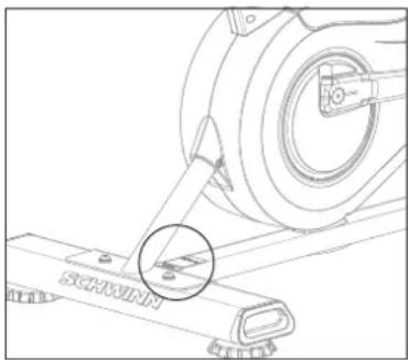
Place the exercise bike on a level surface. There should be 30 cm in front of the exercise bike. For ease of access, there should be an accessible space preferentially on both sides of the exercise bike equal to 2 ft (0.6 meters) to allow a user access to the machine from either side. Do not place the exercise bike in any area that will block any vent or air openings. The exercise bike should not be located in a garage, covered patio, near water or outdoors.
DANGER!
- Improper connection of the equipment-grounding conductor can result in a risk of electric shock. Check with a qualified electrician or service provider if you are in doubt as to whether the product is properly grounded. Do not modify the plug provided with the product. If it does not fit the outlet, have a proper outlet installed by a qualified electrician.
- This product is for use on a nominal local voltage circuit and has a grounding plug. No adapter should be used with this product.
- This product must be used on a dedicated circuit. To determine if you are on a dedicated circuit, shut off the power to that circuit and observe if any other devices lose power. If so, move devices to a different circuit.
Note: There are usually multiple outlets on one circuit.
TECH SPECS
| Assembled Dimensions (L x W x H) | 134.6 x 67.3 x 134.6 cm / 53" x 26.5" x 53" |
| Product Weight | 51.3 kg / 113 lbs. |
| Max User Weight | 159 kg / 350 lbs. |

From now on, you can assemble your equipment at your convenience. For detailed instructions on assembly, operation, programs, troubleshooting, and maintenance, please scan the QR code on the left side to access the complete manual.
If scanning the QR code fails, you can visit the website provided here: https://global.schwinnfitness.com/en/manuals.html
WARRANTY
If your equipment requires warranty service, please contact local Customer Tech Support.

NEED HELP?
If you have any questions, need assistance with missing parts, or require technical support or maintenance for your equipment, please contact Customer Tech Support.
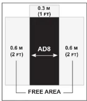
MAIN PARTS INCLUDEED
A decal has been applied to all right ("R") and left ("L") parts to assist with assembly.
| Item | Qty | Description | Item | Qty | Description |
| 1 | 1 | Frame Assembly | 8 | 1 | Stabilizer, Front |
| 2 | 1 | Console / Mast Assembly | 9 | 1 | Foot Peg, Right |
| 3 | 1 | Seat | 10 | 1 | Pedal, Right |
| 4 | 1 | Handlebar, Left | 11 | 1 | Handlebar, Right |
| 5 | 1 | Foot Peg, Left | 12 | 1 | Strap, Transport and Immobilization |
| 6 | 1 | Pedal, Left | 13 | 2 | Batteries, D size (LR20) |
| 7 | 1 | Stabilizer, Rear |
HARDWARE KIT TOOL KIT
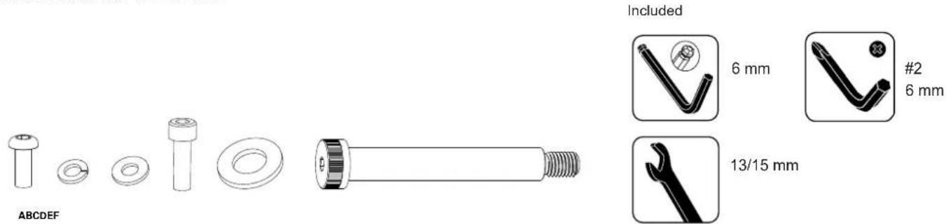
| Item Qty Description Item Qty Description | ||||
| A | 10 Button Head Hex Screw, M8x20 | E | 2 Flat Washer, M16 | |
| B | 10 Lock Washer, M8 | F | 2 Shoulder Screw, M12x100 | |
| C | 10 Flat Washer, M8 | |||
| D | 4 Socket Head Cap Screw, M8x25 | |||
Note: Select pieces of Hardware have been provided as spares on the Hardware Card. Be aware that there may be remaining Hardware after the proper assembly of your machine.
PRE ASSEMBLY
UNPACKING
Due to the weight of the equipment, it is recommended that two people perform the assembly. Unpack the product where you will be using it. It is recommended that you place a protective covering on your floor. Place the carton on a level flat surface and remove all packing materials; do not dispose of the packing materials until assembly is completed.
NOTE: During each assembly step, ensure that ALL nuts and bolts are in place and partially threaded in before completely tightening any ONE bolt.
NOTE: A light application of grease may aid in the installation of hardware. Any grease, such as lithium bike grease is recommended.

NEED HELP?
If you have any questions or if there are any missing parts, please contact Customer Tech Support.
ASSEMBLY
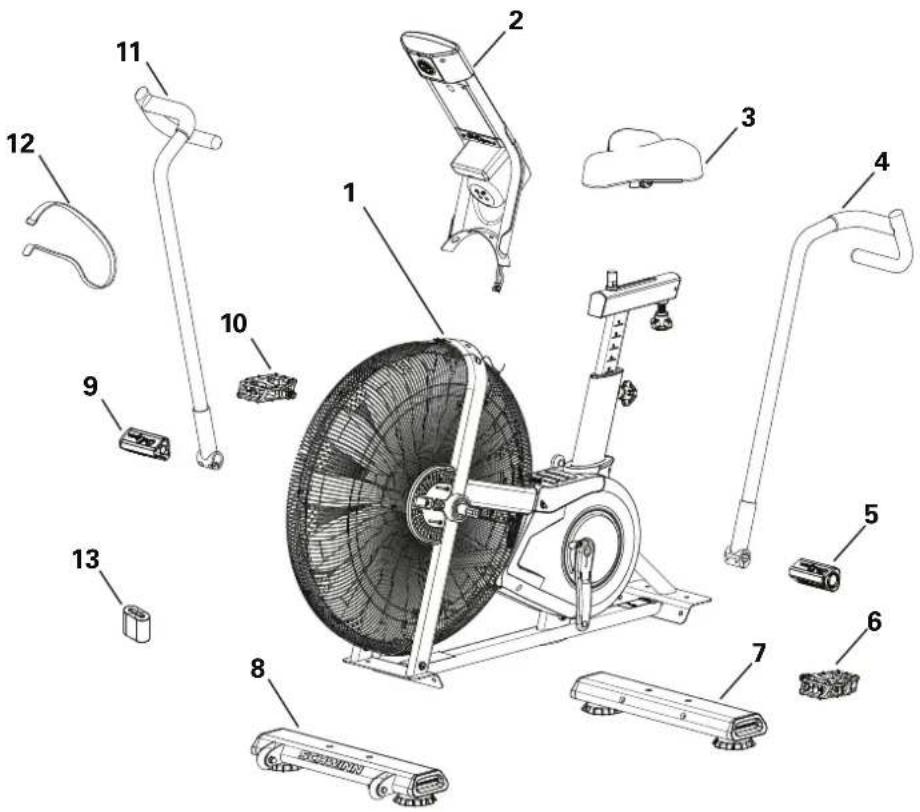
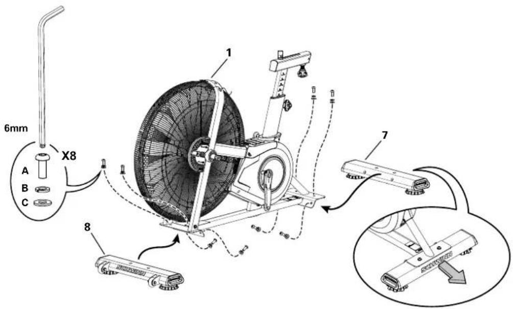
1. Attach Stabilizers to Frame Assembly
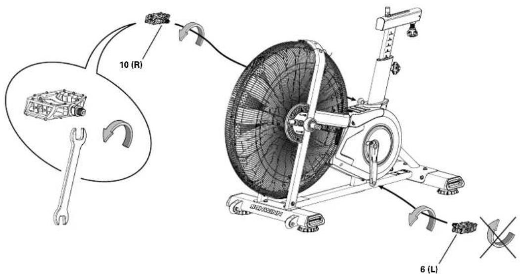
2. Attach Pedals to Frame Assembly
Note: The Left Pedal is reverse-threaded. Be sure to attach Pedals on the proper side of the Bike. Orientation is based from a seated position on the bike. The Left Pedal has an "L", the Right Pedal an "R".
ASSEMBLY
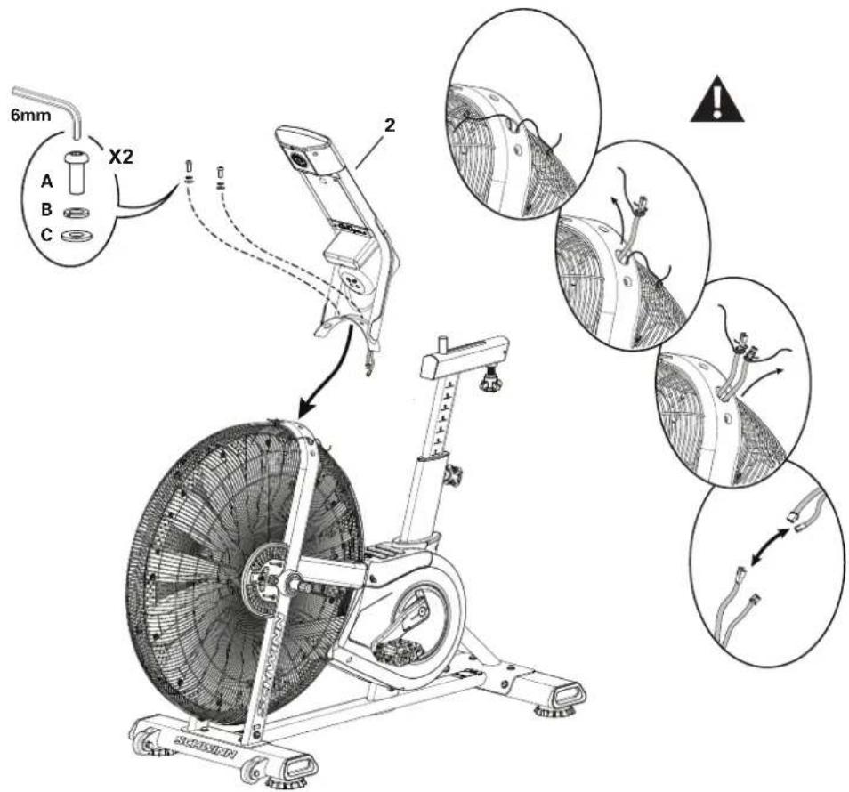
3. Connect Cables and Attach the Console/Mast Assembly to Frame Assembly
NOTICE: Do not crimp the cables.
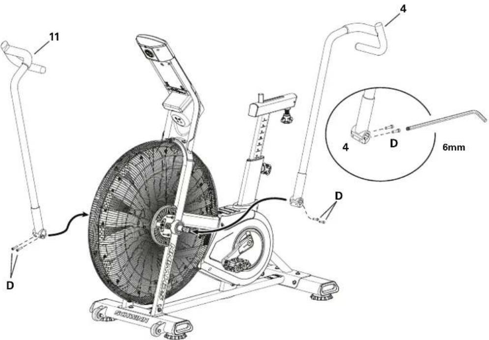
4. Attach Handlebar Arms to Frame Assembly

Fully tighten hardware. Make sure the Handlebar Arms are secure before you exercise. If a torque wrench is available, tighten bolts to 40 N.m.
ASSEMBLY
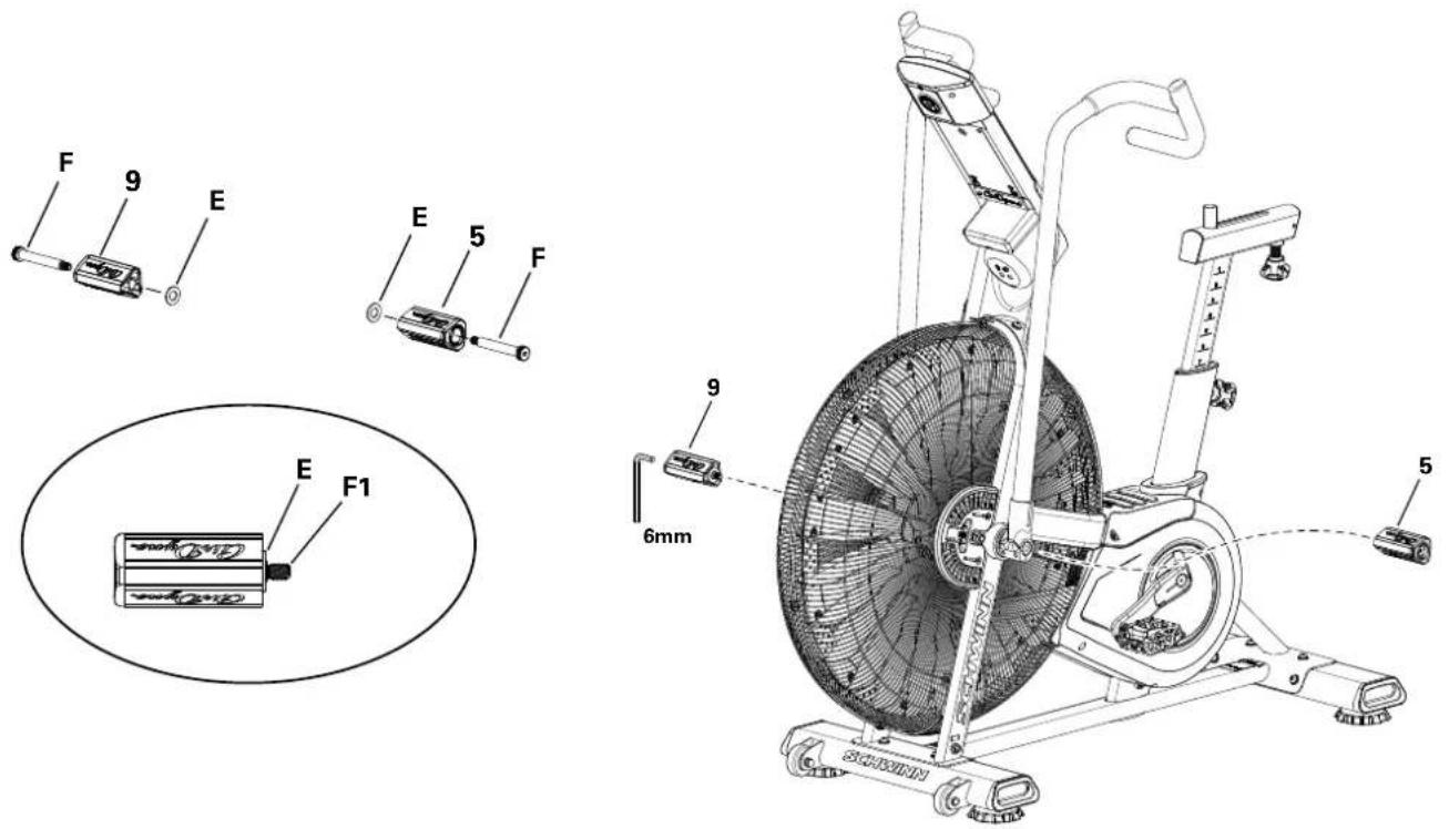
5. Assemble Foot Pegs and Hardware, and Attach Foot Pegs to Frame Assembly
NOTICE: Push the Shoulder Screw (F) completely through the Foot Peg, and press the Washer (E) tightly onto the end of the Foot Peg. Be sure the Washer does not touch the screw threads (F1). Do not let the Washer fall off the Foot Peg during installation.
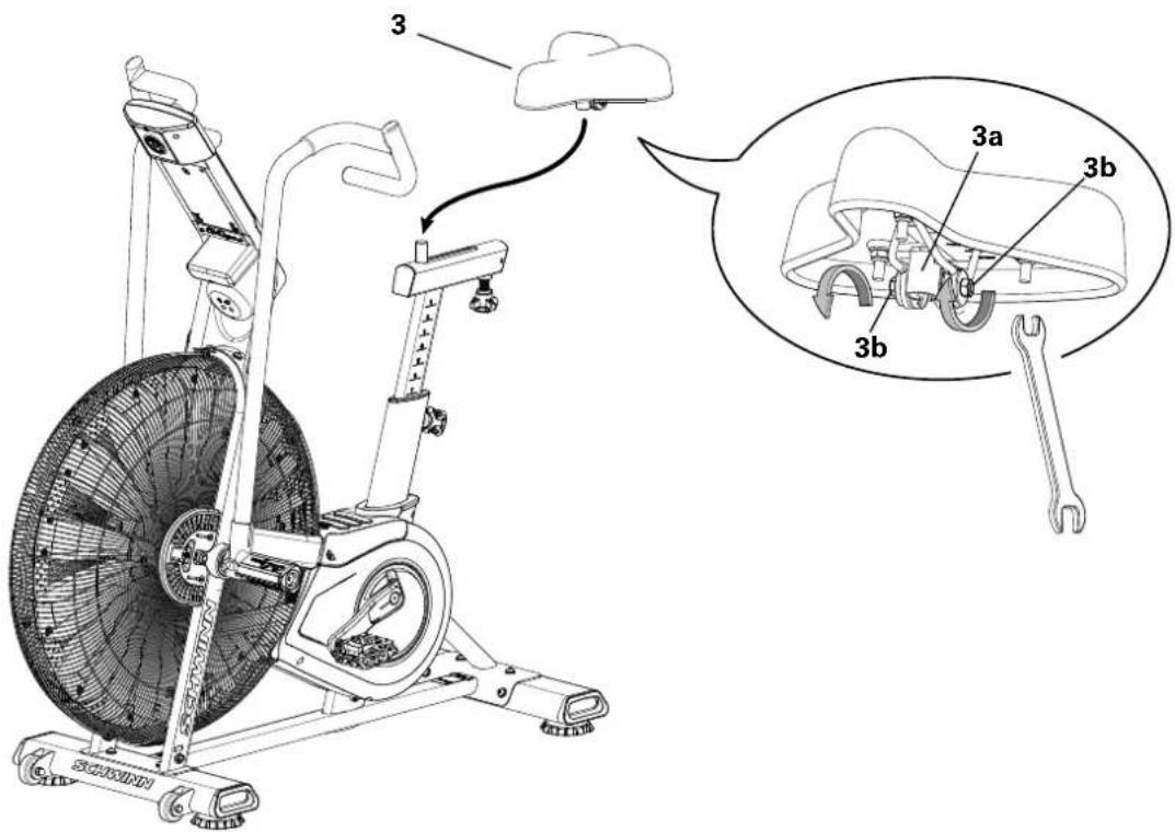
6. Attach Seat to Seat Post
NOTICE: Be sure the Seat is straight. Tighten both nuts (3b) on the Seat bracket (3a) to hold the Seat in position.
ASSEMBLY
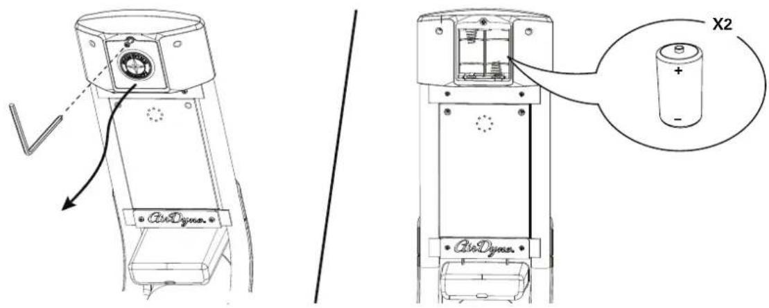
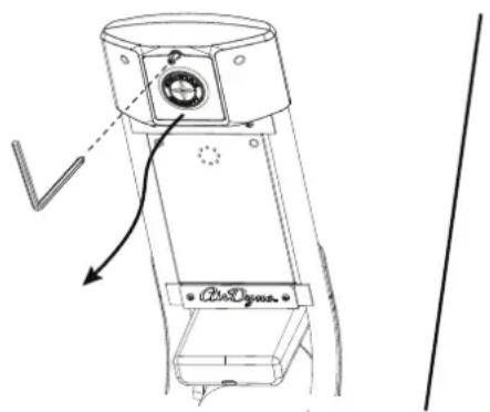
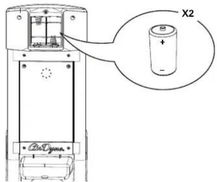
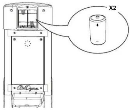
7. Install Batteries in Console
Note: To open the battery bay, loosen the preinstalled screw in the cover. The console uses D size batteries (LR20). Make sure that the batteries point in the direction of the +/- indicators in the battery bay. If you use rechargeable batteries, the optional power adapter will not recharge the batteries.

Do not mix old and new batteries.
Do not mix alkaline, standard (carbon-zinc), or rechargeable (Ni-Cd, Ni-MH, etc) batteries.
8. Final Inspection
Inspect your machine to ensure that all hardware is tight and components are properly assembled.
Be sure to record the serial number in the field provided at the front of this manual.

Do not use or put the machine into service until the machine has been fully assembled and inspected for correct performance in accordance with the Owner's Manual.
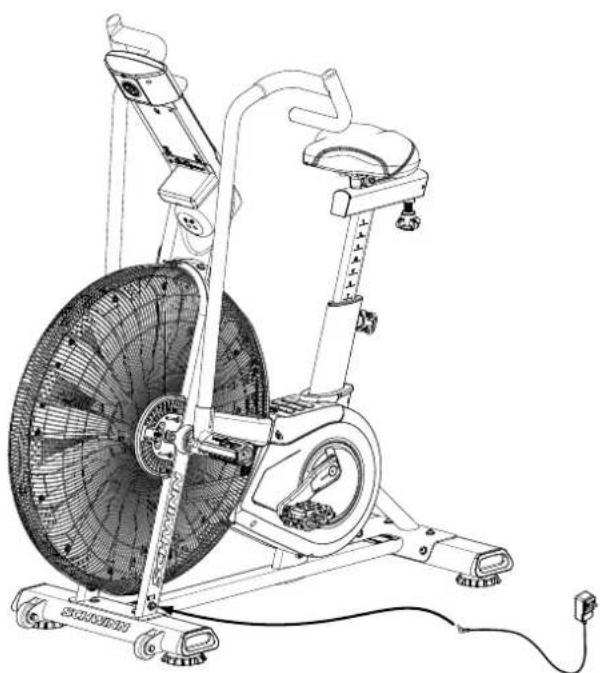
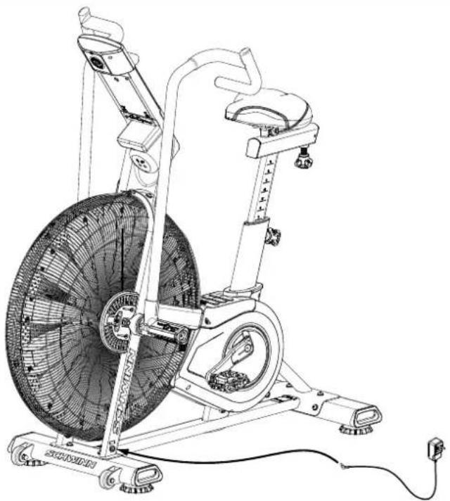
Optional Power Adapter
The console for your machine can operate on battery power or AC power. For AC power, it is necessary to order the optional Power Adapter. If batteries and the Power Adapter are installed, the console will use the Power Adapter to operate.
Note: If you use rechargeable batteries, the optional Power Adapter will not recharge the batteries
After the machine is fully assembled, connect the Power Adapter to the Power Connector and the wall outlet.
NOTICE: If you use a power adapter for your machine, make sure that the cord stays clear of the path of the pedals.
NOTICE: It is recommended to remove batteries when they are not used, to avoid damage from battery corrosion.
To order the optional Power Adapter, go to: www.SchwinnFitness.com/powersupply Or call 1 (800) 605-3369.
natural_image
Line drawing of a stationary exercise bike with visible wheel, wheels, and sensor components (no text or symbols)BEFORE YOU START
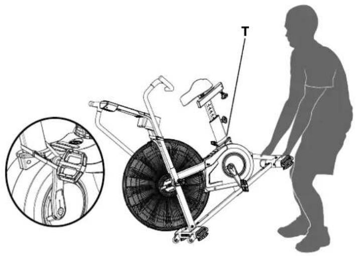
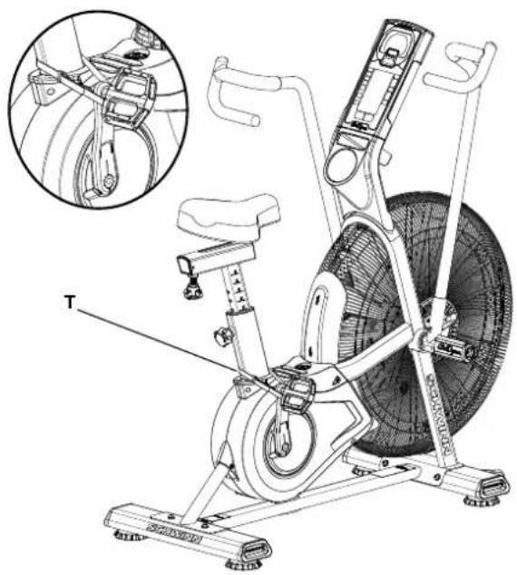
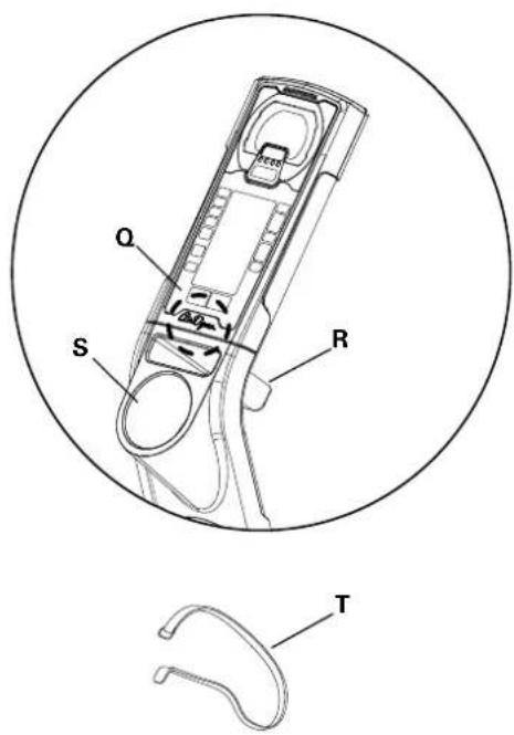
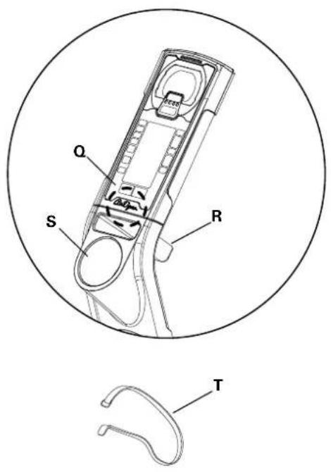
Moving the Machine

The machine may be moved by one or more persons depending on their physical abilities and capacities. Make sure that you and others are all physically fit and able to move the machine safely. Use proper safety precautions and lifting techniques.
- Remove the power adapter.
- Secure the Crank Arm to the Seat Post with the Transport and Immobilization Strap (T).
- Use the Rear Stabilizer to carefully lift the machine onto the transport rollers. Note: Be sure to keep the fan assembly clear of the floor.
- Push the machine into position.
- Carefully lower the machine into position.
NOTICE: Be careful when you move the machine. Abrupt motions can affect the computer operation.
natural_image
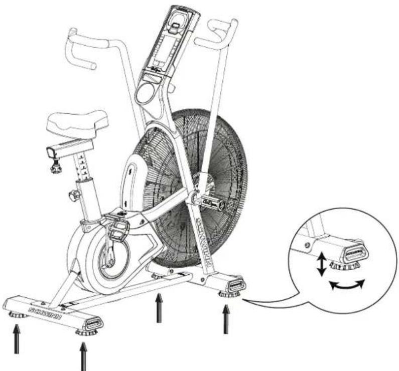
Diagram of a stationary exercise bike with a person standing beside it, showing internal components and a close-up inset (no text or symbols)Leveling the Machine
The machine needs to be leveled if your workout area is uneven. Levelers are on each side of the Stabilizers. To adjust:
- Place the machine in your workout area.
- Turn the stabilizer feet to adjust until they are evenly balanced and in contact with the floor.

Do not adjust the levelers to such a height that they detach or unscrew from the machine. Injury to you or damage to the machine can occur.
Make sure the machine is level and stable before you exercise.
natural_image
Technical line drawing of an exercise bike with labeled components and motion arrows (no text or symbols)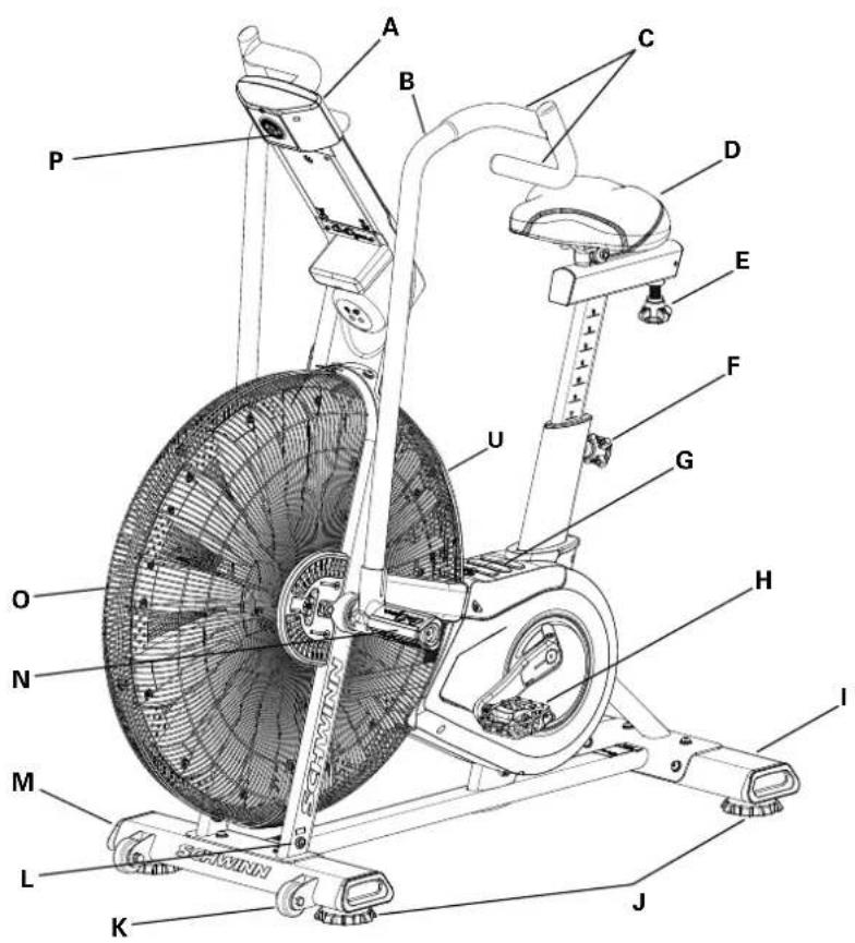

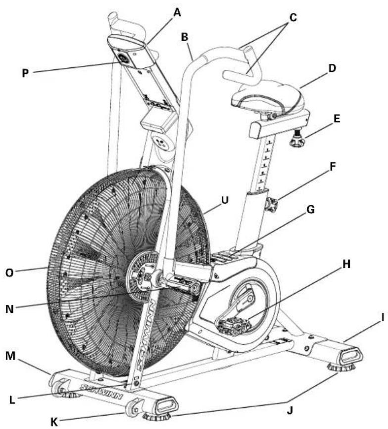
| A | Console | H | Pedal | O | Air Resistance Fan |
| B | Handlebar | I | Stabilizer, Rear | P | Battery Compartment |
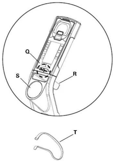
| C | Handle Grip | J | Leveler | Q | Telemetry Heart Rate (HR) Receiver |
| D | Seat | K | Transport Roller | R | Media Rack |
| E | Seat Slider Adjustment Knob | L | Power Connector | S | Water Bottle Holder |
| F | Seat Post Adjustment Knob | M | Stabilizer, Front | T | Transport and Immobilization Strap |
| G | Foot Step Pad | N | Foot Peg | U | AirDyne® Air Diverter |
CONSOLE OPERATION
Console Features
The Console provides information about your workout on the display screens.
Programs
- Manual
• 20/10 Interval
• 30/90 Interval - Custom Interval
- Time Target
- Heart Rate Zones
- Calorie Target
- Kilojoules Target
- Miles Target
- Kilometers Target
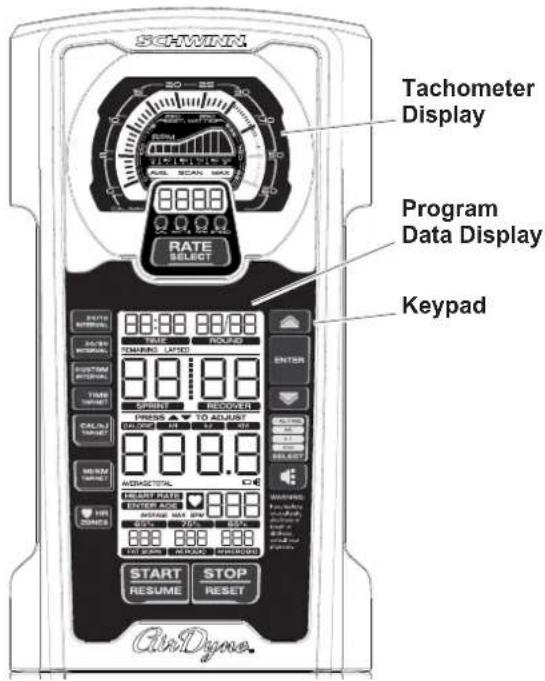
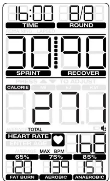
PROGRAM DATA DISPLAY
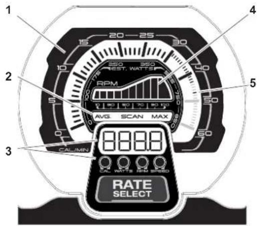
Tachometer Display
- LCD tachometer display — the meter is divided into 60 segments to show CAL/MIN and WATTS metrics for the current workout performance. For CAL/MIN values the meter utilizes two linear scales: each large tick mark segment (0-30) indicates 1 calorie/minute, and each small tick mark segment (30-60) indicates 1 calorie/minute.
- Tach metric labels — indicate the type of values currently shown in the Tach metric display:
• AVG — the Average values display only during workout summary.
• SCAN — in Scan mode the tach automatically moves through the rate metrics. Each rate display shows for 3 seconds. -
MAX — the Maximum values display only during workout summary.
-
Tach metric display — shows the numeric values for the following rates:
-
CAL/MIN — the estimated calories burned per minute (based on the Watts metric). The maximum display is 999.9.
- WATTS — the power that you are producing at the current resistance level (1 horsepower = 746 watts). Maximum value is 999.9.
- RPM — the machine revolutions per minute (RPM). The maximum display is 9999.
-
SPEED — the machine speed in miles per hour, to one decimal place — for example, 10.5. The maximum display is 999.9.
-
Tach hill — represents the user's RPM performance on a 1-100 linear scale (divided into 10 segments).
-
MAX CAL/MIN tick mark — the highest tick mark achieved (on the LCD tachometer display) stays on to show the maximum effort during the current workout.
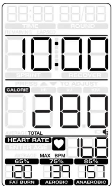
PROGRAM DATA DISPLAY
6. TIME
The TIME display field is used for Interval workouts only. During the workout, it shows the remaining time. During workout summary it shows the total time.
7. ROUND
The ROUND display field is used for Interval workouts only. The first 00 segment shows the number of the current round. The second 00 segment shows the total number of rounds. The maximum number of rounds is 49.
8. TIME/INTERVAL area
The TIME/INTERVAL display field has two modes: Default and Interval. The Sprint and Recover labels are enabled for Interval programs only. Default mode shows lapsed or remaining time, depending on the program in use. Time ticks up to 99 minutes and 59 seconds (the maximum time). Interval mode shows the workout state (Sprint/Recover) and remaining time in that state. The maximum is 99 seconds in each state.
9. PRESS ▲/▼ TO ADJUST
The prompt "PRESS ▲/▼ TO ADJUST" shows only before a workout for the option to Increase/Decrease a target or number of intervals. The customizable metric flash-es until it is adjusted.
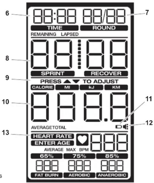
10. Cumulative metrics
The cumulative metrics display field shows the work (CALORIES, kJ) or distance (MI, KM) achieved during the workout. Manual and Interval programs start at 0 and count up. In Target programs the target metric counts down to 0, but the other metrics count up. Push the CAL MI Kj KM Select button to move to each metric.
The AVERAGE and TOTAL labels identify the values in the workout summary.
11. Battery indicator
The battery indicator turns on when the battery level is 25% or less.
12. Volume
The volume icon for the audio alert is always on. The three dots to the right indicate the volume setting. (Off: icon shows no dots, Full: icon shows three dots.)
13. HEART RATE area
The HEART RATE display shows the heart rate in beats per minute (BPM) from a telemetric heart rate sensor. The icon will flash when it has a signal from a telemetric heart rate strap. This display value will be blank if a heart rate signal is not detected. The AVERAGE and MAX labels identify the HR values in the workout summary.

Consult a physician before you start an exercise program. Stop exercising if you feel pain or tightness in your chest, become short of breath, or feel faint. Contact your doctor before you use the machine again. Use the values calculated or measured by the machine's computer for reference purposes only. The heart rate displayed on the console is an approximation and should be used for reference only.
The prompt "ENTER AGE" turns on if the user presses the HR ZONES button. The default age is 35.
The values in the FAT BURN, AEROBIC and ANAEROBIC heart rate zone fields are calculated from the Age value.
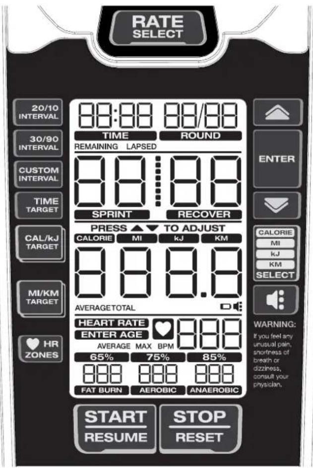
KEYPAD FUNCTIONS
RATE SELECT button- Cycles through the Tach metric display options (CAL/MIN, WATTS, RPM, SPEED). Push and hold the button for 3 seconds to go to SCAN mode and cycle through the rates automatically. Each rate is displayed for 3 seconds. To exit SCAN mode, push the Rate Select button.
20/10 INTERVAL button- Selects the 20/10 Interval workout.
30/90 INTERVAL button- Selects the 30/90 Interval workout.
CUSTOM INTERVAL button- Selects the Custom Interval workout.
TIME TARGET button- Selects the Time Target workout.
CAL/kJ TARGET button- Push one time to select the CAL Target workout. Push two times to select the kJ Target workout.
MI/KM TARGET button- Push one time to select the MI Target workout. Push two times to select the KM Target workout.
HR ZONES button- Push before or during any workout to start the Heart Rate Zones calculation.
Increase (▲) button- Increases a value (time, target or age) or moves through options. Push and hold for quick access.
ENTER button- Confirms a setting for HR Zones and the Custom Interval program.
Decrease (▼) button- Decreases a value (time, target or age) or moves through options. Push and hold for quick access.
CAL MI Kj KM Select button- Cycles through the cumulative metrics.
Volume button- Moves through the four volume levels for the audio alert: Off, low, med (default), high, med, low, off
START/RESUME button- Starts the timer, and resumes a paused workout
STOP/RESET button- Push one time to stop the workout and display
summary. Push two times to reset the console and erase data (except Custom Interval program).
Remote Heart Rate Monitor
Monitoring your Heart Rate is one of the best procedures to control the intensity of your exercise. The Console can read telemetry HR signals from a Heart Rate Chest Strap Transmitter that operates in the 4.5kHz - 5.5kHz range.
Note: The heart rate chest strap must be an uncoded heart rate strap from Polar Electro or an uncoded POLAR® compatible model. (Coded POLAR® heart rate straps such as POLAR® OwnCode® chest straps will not work with this equipment.)

If you have a pacemaker or other implanted electronic device, consult your doctor before using a wireless chest strap or other telemetric heart rate monitor.
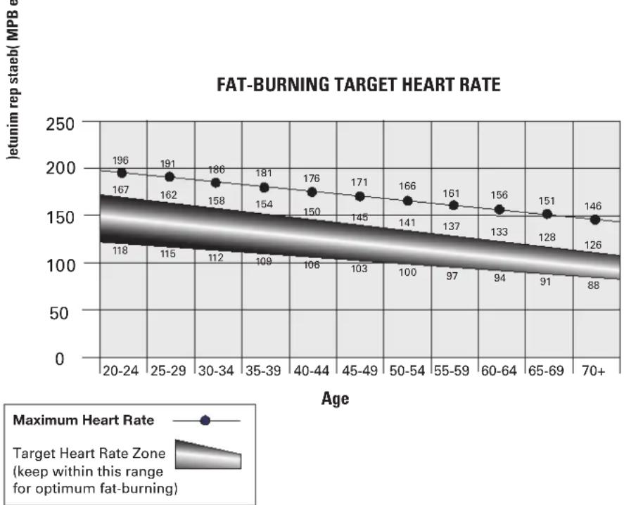
Heart Rate Calculations
Your maximum heart rate usually decreases from 220 Beats Per Minute (BPM) in childhood to approximately 160 BPM by age 60. This fall in heart rate is usually linear, decreasing by approximately one BPM for each year. There is no indication that training influences the decrease in maximum heart rate. Individuals of the same age could have different maximum heart rates. It is more accurate to find this value by completing a stress test than by using an age related formula.
Your at-rest heart rate is influenced by endurance training. The typical adult has an at-rest heart rate of approximately 72 BPM, where as highly trained runners may have readings of 40 BPM or lower.
The Heart Rate table is an estimate of what Heart Rate Zone (HRZ) is effective to burn fat and improve your cardiovascular system. Physical conditions vary, therefore your individual HRZ could be several beats higher or lower than what is shown.
The most efficient procedure to burn fat during exercise is to start at a slow pace and gradually increase your intensity until your heart rate reaches between 60 – 85% of your maximum heart rate. Continue at that pace, keeping your heart rate in that target zone for over 20 minutes. The longer you maintain your target heart rate, the more fat your body will burn.
The graph is a brief guideline, describing the generally suggested target heart rates based on age. As noted above, your optimal target rate may be higher or lower. Consult your physician for your individual target heart rate zone.
Note: As with all exercises and fitness regimens, always use your best judgment when you increase your exercise time or intensity.
line
| Age | Maximum Heart Rate (MPB) | |-------|--------------------------| | 20-24 | 196 | | 25-29 | 191 | | 30-34 | 186 | | 35-39 | 181 | | 40-44 | 176 | | 45-49 | 171 | | 50-54 | 166 | | 55-59 | 161 | | 60-64 | 156 | | 65-69 | 151 | | 70+ | 146 |Auto-Calibration
The console has a built-in sensor which continually corrects for changes in altitude to maintain accurate measurement of fan resistance and watts used during exercise.
OPERATION
What to Wear
Wear rubber-soled athletic shoes. You will need the appropriate clothes for exercise that allow you to move freely.
How Often Should You Exercise

Consult a physician before you start an exercise program. Stop exercising if you feel pain or tightness in your chest, become short of breath, or feel faint. Contact your doctor before you use the machine again. Use the values calculated or measured by the machine's computer for reference purposes only. The heart rate displayed is an approximation and should be used for reference purposes only.
• 3 times a week for 30 minutes each day.
- Schedule workouts in advance and try to follow the schedule.
Seat Adjustment
Correct seat placement encourages exercise efficiency and comfort, while reducing the risk of injury.
- With a Pedal in the forward position, place the heel of your foot to the lowest part of it. Your leg should be bent slightly at the knee.
- If your leg is too straight or your foot cannot touch the Pedal, you need to move the seat downward. If your leg is bent too much, you need to move the seat upward.

off the machine before you adjust the seat.
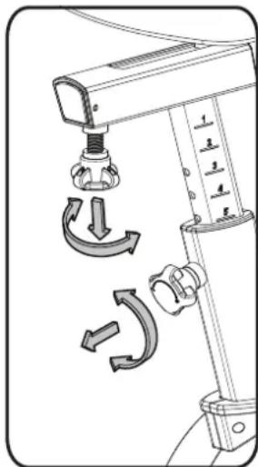
- Loosen and pull the Seat Post Adjustment Knob on the Seat Post. Adjust the seat to the desired height.

ot lift the Seat post above the "STOP" mark on the Seat Post.
- Release the Seat Post Adjustment Knob to engage the locking pin. Be sure that the pin is fully engaged and fully tighten the adjustment knob.
- To move the seat closer to, or away from the console, loosen the seat adjustment knob. Slide the seat to the desired position and fully tighten the knob.
natural_image
Technical diagram of a mechanical device with directional arrows indicating motion or rotation (no text or symbols)Using the Machine

Be aware that the Pedals, Handlebars and Resistance Fan are connected and when any of these parts move the others do as well. Carefully mount the machine using the Foot Step Pad if necessary. Adjust the Seat and Pedals before starting a workout.
Lower Body Workout: Slowly pedal with your arms relaxed at your sides or with your hands resting on the Hand Grips as the Handlebars move.
Full Body Workout: Grasp the Hand Grips with your palms down. Push and pull the Handlebars as you pedal, keeping your elbows low and next to your body.
Upper Body Workout: Grasp the Hand Grips firmly with palms down and place your feet on the Foot Pegs. Lean slightly forward at the hips with your back straight and shoulders down. Now push and pull the Handlebars
Note: You may need to safely push a Pedal to assist with starting the workout.
To increase the air resistance and workload, increase your level of activity. To exercise all the muscle groups in your arms, alter your grasp to palms up for part of the workout.
OPERATION
Wear rubber-soled athletic shoes. You will need the appropriate clothes for exercise that allow you to move freely.
How Often Should You Exercise

Consult a physician before you start an exercise program. Stop exercising if you feel pain or tightness in your chest, become short of breath, or feel faint. Contact your doctor before you use the machine again. Use the values calculated or measured by the machine's computer for reference purposes only. The heart rate displayed is an approximation and should be used for reference purposes only.
• 3 times a week for 30 minutes each day.
- Schedule workouts in advance and try to follow the schedule.
Seat Adjustment
Correct seat placement encourages exercise efficiency and comfort, while reducing the risk of injury.
- With a Pedal in the forward position, place the heel of your foot to the lowest part of it. Your leg should be bent slightly at the knee.
- If your leg is too straight or your foot cannot touch the Pedal, you need to move the seat downward. If your leg is bent too much, you need to move the seat upward.

off the machine before you adjust the seat.
- Loosen and pull the Seat Post Adjustment Knob on the Seat Post. Adjust the seat to the desired height.

Not lift the Seat post above the "STOP" mark on the Seat Post.
- Release the Seat Post Adjustment Knob to engage the locking pin. Be sure that the pin is fully engaged and fully tighten the adjustment knob.
- To move the seat closer to, or away from the console, loosen the seat adjustment knob. Slide the seat to the desired position and fully tighten the knob.
Using the Machine

Be aware that the Pedals, Handlebars and Resistance Fan are connected and when any of these parts move the others do as well. Carefully mount the machine using the Foot Step Pad if necessary. Adjust the Seat and Pedals before starting a workout.
Lower Body Workout: Slowly pedal with your arms relaxed at your sides or with your hands resting on the Hand Grips as the Handlebars move.
Full Body Workout: Grasp the Hand Grips with your palms down. Push and pull the Handlebars as you pedal, keeping your elbows low and next to your body.
Upper Body Workout: Grasp the Hand Grips firmly with palms down and place your feet on the Foot Pegs. Lean slightly forward at the hips with your back straight and shoulders down. Now push and pull the Handlebars
Note: You may need to safely push a Pedal to assist with starting the workout.
To increase the air resistance and workload, increase your level of activity. To exercise all the muscle groups in your arms, alter your grasp to palms up for part of the workout.
OPERATION
When done with your workout, reduce the Resistance Fan speed until the machine fully stops.

This bike cannot stop the Pedals independently of the Resistance Fan. Reduce the pace to slow the Resistance Fan and Pedals to a stop. Do not dismount the bike until the Pedals have come to a complete stop. Be aware that the moving Pedals can strike the backs of the legs.
Locking the Fan Assembly / Storage
When the machine is not in use, be sure to lock the Fan Assembly with the Transport and Immobilization Strap. The fan assembly should be locked for storage of the machine.

For safe storage of the machine, remove the batteries and install the Transport and Immobilization Strap to secure the Resistance Fan. Place the machine in a secure location from children and pets. Be aware that the Pedals, Handlebars and Resistance Fan are connected and when any of these parts move, the others do as well.
To lock the Fan Assembly:
- Move the Pedals so that one Crank Arm is as close as possible to the Seat Post.
- Wrap the Transport and Immobilization Strap (T) around the Crank Arm and the Seat Post and put the end of the strap through the metal ring. Tighten the strap to prevent movement of the Pedals and secure the strap.
Power-Up / Idle Mode
The Console will enter Power-Up / Idle Mode if any button is pushed, or if it receives a signal from the RPM sensor as a result of pedaling the machine.
Note: The Console will display the battery indicator if the battery level is 25% or less.
natural_image
Technical line drawing of an exercise bike with labeled components and a close-up inset showing the wheel assembly (no text or symbols present)Auto Shut-Off (Sleep Mode)
If the Console does not receive any input in approximately 2 minutes, it will automatically shut off. The LCD display is off while in Sleep Mode. Note: The Console does not have an On/Off switch.
Manual Workout
The Manual program lets you start a workout without entering any information.
- Sit on the machine.
- With the Console in Idle Mode, push the START/RESUME button to start the workout program, and start to pedal.
- To pause the workout and see your metrics, push the STOP/RESET button one time. Push START/RESUME to continue.
- When done with your workout, push the STOP/RESET button two times to end the workout.
20/10 Interval Workout
The Console allows you to select an Interval workout of 20 seconds Sprint followed by 10 seconds Recover (1 round). The default number of rounds is 8 rounds (total time - 4 minutes).
- Sit on the machine.
- With the Console in Idle Mode, push the 20/10 INTERVAL button.
- The ROUND field blinks (default value is 8). To change the number of rounds, use the Increase/Decrease buttons.
- Push the START/RESUME button to start the timer, and start to pedal.
- The program starts in the Sprint phase and counts down each phase and the total workout time. The work and distance values count up. An audible alert sounds 3 seconds before each phase change.
OPERATION
Time Target Workout
The Console allows you to select a Time Target workout and enter your own Time value. The default value is 10 minutes.
- Sit on the machine.
- With the Console in Idle Mode, push the TIME TARGET button.
- The TIME/INTERVAL field blinks (default value is 10:00). To change the value, use the Increase/Decrease buttons to adjust in 1 minute increments.
- Push the START/RESUME button to start the timer, and start to pedal.
- The program starts and counts down the time. The CALORIE, kJ, MI and KM values count up.
Calories Target Workout
The Console allows you to select a Calories Target workout and enter your own Calories value. The default value is 100 calories.
- Sit on the machine.
- With the Console in Idle Mode, push the CAL/kJ TARGET button one time.
- The CALORIE metrics field blinks (default value is 100). To change the value, use the Increase/Decrease buttons to adjust in 25 calorie increments.
- Push the START/RESUME button to start the timer, and start to pedal.
- The program starts and counts down the calories. The total time, kJ, MI and KM values count up.
Kilojoules (kJ) Target Workout
The Console allows you to select a Kilojoules Target workout and enter your own Kilojoules value. The default value is 400 kilojoules.
- Sit on the machine.
- With the Console in Idle Mode, push the CAL/kJ TARGET button two times.
- The kJ metrics field blinks (default value is 400). To change the value, use the Increase/Decrease buttons to adjust in 100 kilojoule increments.
- Push the START/RESUME button to start the timer, and start to pedal.
- The program starts and counts down the kilojoules. The total time, CALORIE, MI and KM values count up.
Miles Target Workout
The Console allows you to select a Miles Target workout and enter your own Miles value. The default value is 1 mile.
- Sit on the machine.
- With the Console in Idle Mode, push the MI/KM TARGET button one time.
- The MI metrics field blinks (default value is 1.0). To change the value, use the Increase/Decrease buttons to adjust in 0.5 mile increments.
- Push the START/RESUME button to start the timer, and start to pedal.
- The program starts and counts down the miles. The total time, CALORIE, kJ and KM values count up.
Kilometers Target Workout
The Console allows you to select a Kilometers Target workout and enter your own Kilometers value. The default value is 1 kilometer.
- Sit on the machine.
- With the Console in Idle Mode, push the MI/KM TARGET button two times.
- The KM metrics field blinks (default value is 1.0). To change the value, use the Increase/Decrease buttons to adjust in 1 kilometer increments.
- Push the START/RESUME button to start the timer, and start to pedal.
- The program starts and counts down the kilometers. The total time, CALORIE, kJ and MI values count up.
Heart Rate Zones
The Console allows you to set your Heart Rate Zones and use the calculated values to monitor your workout intensity. This feature can be used in conjunction with all of the other programs.
- Sit on the machine.
- With the Console in Idle Mode, push the HR ZONES button. The prompt "ENTER AGE" turns on. The default age is 35. To adjust the Age value, use the Increase/Decrease buttons and push ENTER.
The Console calculates values for the FAT BURN, AEROBIC and ANAEROBIC heart rate zone fields from the Age value.
OPERATION

Consult a physician before you start an exercise program. Stop exercising if you feel pain or tightness in your chest, become short of breath, or feel faint. Contact your doctor before you use the machine again. Use the values calculated or measured by the machine's computer for reference purposes only. The heart rate displayed on the console is an approximation and should be used for reference only.
- The HEART RATE display shows the heart rate in beats per minute (BPM) from a heart rate chest strap transmitter. The icon will flash when it has a signal from a HR chest strap.
Note: If no heart rate is detected, the display will be blank.
When the Console goes into Sleep Mode or the power is removed, the Age value is reset to default and the HR Zones turn off.
Pausing / Results Mode
To pause a workout and see the workout summary:
-
Push the STOP/RESET button one time.
Note: The Console will automatically pause if there is no RPM signal for 5 minutes. -
To continue your workout, push START/RESUME.
To end the workout, push the STOP/RESET button two times. The Console will go into Idle Mode.
When you complete or stop a workout, the Console will display a summary of your workout values. To stop a workout and see the summary, push STOP/RESET and the Console will go into Results mode.
The Tachometer Display shows the user's average CAL/MIN and WATTS, and the MAX CAL/MIN tick mark for that workout. The Tach hill shows the average RPM. The Tach metric display shows the average and maximum values for the selected metric. If the console was in SCAN mode, the display cycles through the average and maximum values for CAL/MIN, WATTS, RPM and SPEED.
The Program Data Display shows the total time, CALORIE, MI (miles), kJ (kilojoules), and KM (kilometers) metrics. Push the CAL MI Kj KM Select button to cycle through the metrics. The summary for Interval programs shows total time, rounds and interval time.
Manual and Target Programs
Interval Programs
The Heart Rate area cycles the Average HR and MAX HR values. If HR Zones were calculated for the program, the values are displayed.
The Results display will show for 5 minutes and then reset.
Push STOP/RESET to stop the Results display and go back to Idle Mode.
CONSOLE SERVICE MODE
The Console Service Mode lets you see the total time and distance the machine has been used, adjust the altitude value for a more accurate calorie count, or find out which version of Firmware is installed.
- Hold down the STOP/RESET button and Decrease (▼) button together for 3 seconds while in the Idle Mode to go into the Console Service Mode.
-
The Console display shows the machine statistics:
-
Total Machine Time—number of hours (in Time/Interval field). Maximum display is 9999.
- Total Machine Distance—number of miles (in cumulative metrics field). Push the Decrease button to go to the metric display option:
- Total Machine Time—number of hours (in Time/Interval field). Maximum display is 9999.
-
Total Machine Distance—number of kilometers in 10-kilometer increments (in cumulative metrics field).
-
Push STOP/RESET to exit Console Service Mode. Push the Decrease button to go to the next option.
- The Console display shows CAL (calibration). To calibrate the machine, refer to the "Calibration Procedure" section. Push the Decrease button to go to the next option.
- The Console display shows the Firmware Version.
- Push STOP/RESET to exit Console Service Mode.
In Service Mode if the Console does not receive any input in approximately 2 minutes, it goes into Sleep Mode.
TROUBLESHOOTING
| Condition/Problem Things | to Check Solution | |
| Console will not power up/turn on/start | If bike has AC adapter, check electrical (wall) outlet | Make sure unit is plugged into a functioning wall outlet. |
| If bike has AC adapter, check connection at unit | Connection should be secure and undamaged. Replace adapter or connection at unit if either are damaged. | |
| If bike has batteries, check Battery Indicator on console or check batteries | Make sure batteries are installed correctly. If batteries are correctly installed, replace with a set of new batteries. | |
| Check data cable integrity All wires | in cable should be intact. If any are visibly crimped or cut, replace cable. | |
| Check data cable connections/orientation | Make sure cable is connected securely and oriented properly. Small latch on connector should line up and snap into place. | |
| Check console display for damage | Check for visual sign that console display is cracked or otherwise damaged. Replace Console if damaged. | |
| If the above steps do not resolve the problem, contact Customer Care for further assistance. | ||
| Speed displayed is not accurate | Check Speed Sensor Magnet position (requires fan cover removal) | Speed Sensor Magnets should be in place on Fan assembly. |
| Speed displayed is always “0”/stuck in Pause mode | Data cable Make sure the data cable is connected to the back of the Console and the main frame assembly. | |
| Speed Sensor (requires fan cover removal) | Make sure the Speed Sensor Magnets and the Speed Sensor are in place. | |
| No speed/RPM reading | Check data cable integrity | All wires in cable should be intact. If any are cut or crimped, replace cable. |
| Check data cable connections/orientation | Be sure cable is connected securely and oriented properly. Small latch on connector should line up and snap into place. | |
| Check Speed Sensor Magnet position (requires fan cover removal) | Magnets should be in place on Fan assembly. | |
| Check Speed Sensor Assembly (requires fan cover removal) | Speed Sensor Assembly should be aligned with magnets and connected to data cable. Realign sensor if necessary. Replace if there is any damage to the sensor or the connecting wire. | |
| Console displays battery icon Batteries | Replaces batteries | |
| Unit operates but Telemetric Heart Rate not displayed | Chest Strap (optional) Strap should be “POLAR 5” compatible and uncoded. Make sure strap is directly against skin and contact area is wet. | |
| Chest Strap Batteries If strap has replaceable batteries, install new batteries. | ||
| Interference Try moving unit away from sources of interference (TV, Microwave, etc). | ||
| Replace Chest Strap If interference is eliminated and HR does not function, replace strap. | ||
| Replace Console If HR still does not function, replace Console. | ||
TROUBLESHOOTING
| Condition/Problem Things | to Check Solution | |
| Console shuts off (enters sleep mode) while in use | Check data cable integrity All wires | in the cable should be intact. If any are cut or crimped, replace cable. |
| Check data cable connections/orientation | Be sure cable is connected securely and oriented properly. Small latch on connector should line up and snap into place. | |
| If bike has batteries, check Battery Indicator on console or check batteries. | Make sure batteries are installed correctly. If batteries are correctly installed, replace with a set of new batteries. | |
| Check Speed Sensor Magnet position (requires fan cover removal) | Speed Sensor Magnets should be in place on Fan assembly. | |
| Check Speed Sensor Assembly C | Contact Customer Care for further assistance. | |
| Console displays “err 1” message | Check Console keypad for stuck key | Contact Customer Care for further assistance. |
| Unit rocks/does not sit level Check | leveler adjustment Leveling feet may be turned in or out to level bike. | |
| Check surface under unit Adjustment may not be able to compensate for extremely uneven surfaces. Move bike to level area. | ||
| Pedals loose/unit difficult to pedal | Check pedal to crank connection P | Pedal should be tightened securely to crank arm. Be sure connection is not cross-threaded. |
| Check crank arm to axle connection | Crank arm should be tightened securely to axle. (Screw torque = 60 N.m.) | |
| Crank link to pulley connection If the left crank arm still feels loose with correct torque applied and the crank link shaft is moving with the crank arm, replace the crank link assembly. | ||
| Clicking sound when pedaling | Check pedal to crank connection | Remove pedals. Make sure there is no debris on threads, and reinstall the pedals. |
| Check fan alignment (requires fan cover removal) | Refer to the “Adjust the Belt Tension” procedure in the Service Manual. | |
| Seat post movement Check locking | pin Be sure adjustment pin is locked into one of the seat post adjustment holes. | |
| Check locking knob Be sure knob | is securely tightened. | |
| Handlebar arms click/tick during movement | Check hardware | Screws at the base of handlebar arms should be tightened securely. (Screw torque = 40 N.m.) |
MAINTENANCE
Read all maintenance instructions fully before you start any repair work. In some conditions, an assistant is required to do the necessary tasks.

Equipment must be regularly examined for damage and repairs. The owner is responsible to make sure that regular maintenance is done. Worn or damaged components must be repaired or replaced immediately. Only manufacturer supplied components can be used to maintain and repair the equipment.
If at any time the Warning labels become loose, unreadable or dislodged, contact Schwinn Fitness Customer Service for replacement labels.
Disconnect all power to the machine before you service it.
Daily:
Before each use, examine the exercise machine for loose, broken, damaged, or worn parts. Do not use if found in this condition. Repair or replace all parts at the first sign of wear or damage. After each workout, use a damp cloth to wipe your machine and Console free of moisture.
Note: Avoid excessive moisture on the Console.
NOTICE: If necessary, only use a mild dish soap with a soft cloth to clean the Console. Do not clean with a petroleum based solvent, automotive cleaner, or any product that contains ammonia. Do not clean the Console in direct sunlight or at high temperatures. Be sure to keep the Console free of moisture.
Weekly: Clean the machine to remove any dust, dirt, or grime from the surfaces.
Check for smooth seat operation. If needed, sparingly apply a thin coating of silicone lube to ease operation.

Silicone lubricant is not intended for human consumption. Keep out of reach of children. Store in a safe place.
Note: Do not use petroleum based products.
Monthly or after 20 hours:
Check pedals, crank arms and handlebars. Make sure all bolts and screws are tight. Tighten as necessary. Check drive belt for signs of wear. Rotate crank arms by hand and observe the belt through the fan cage.

Be aware that the Crank Arms, Handlebars and Resistance Fan are connected and when any of these parts move, the others do as well.

Only use replacement Pedals available from Schwinn Fitness. Other brands of Pedals may not be designed for Indoor Cycling or this product, and can cause danger to users and bystanders.
Replacing the Console Batteries
The Console will display the Battery Indicator icon when the batteries are around 25% of their rated power during power up. If you use rechargeable batteries, the optional power adapter will not recharge the batteries.
To open the battery bay, loosen the preinstalled screw in the cover. When replacing the batteries, make sure the batteries point in the +/- direction shown in the battery bay.
Note: The console uses D size batteries (LR20)

Do not mix old and new batteries.
Do not mix alkaline, standard (carbon-zinc), or rechargeable (Ni-Cd, Ni-MH, etc) batteries.
natural_image
Technical line drawing of a mechanical device with a dial and base, showing no text or symbols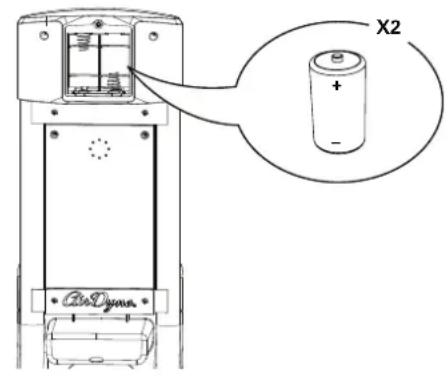

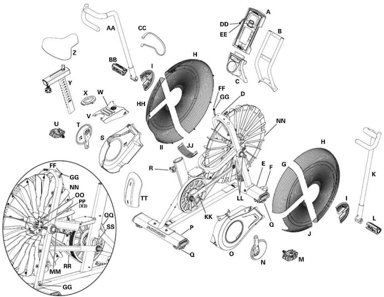
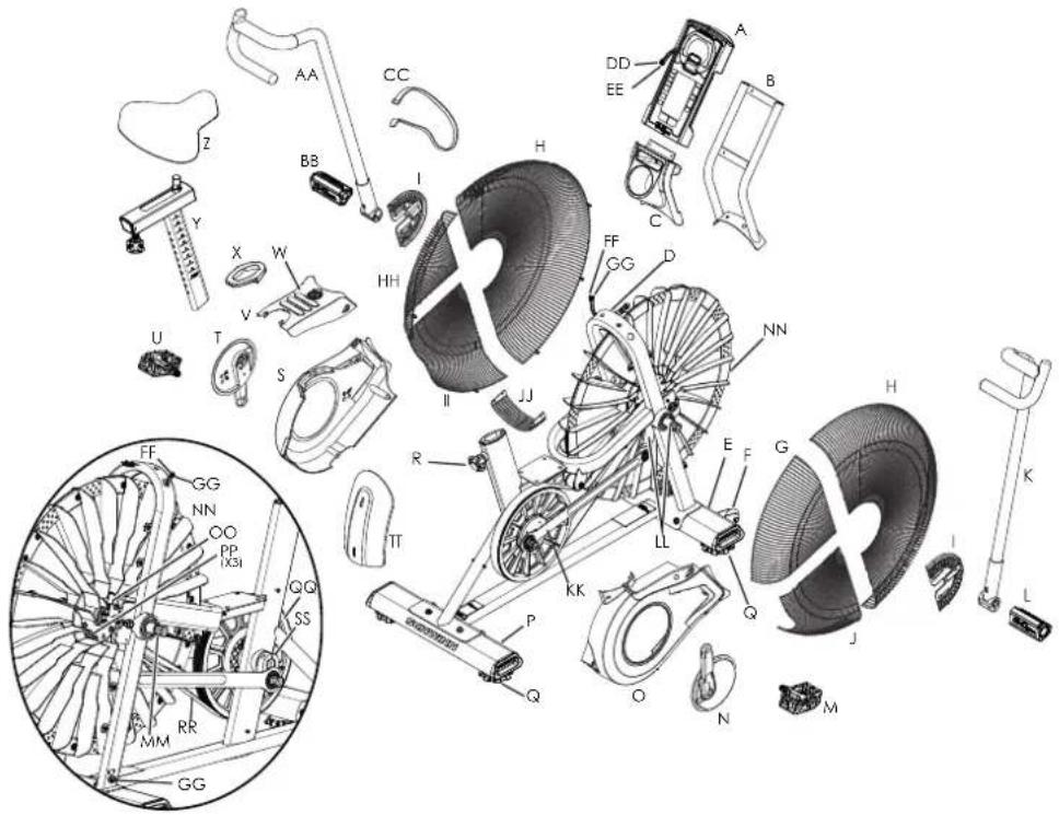
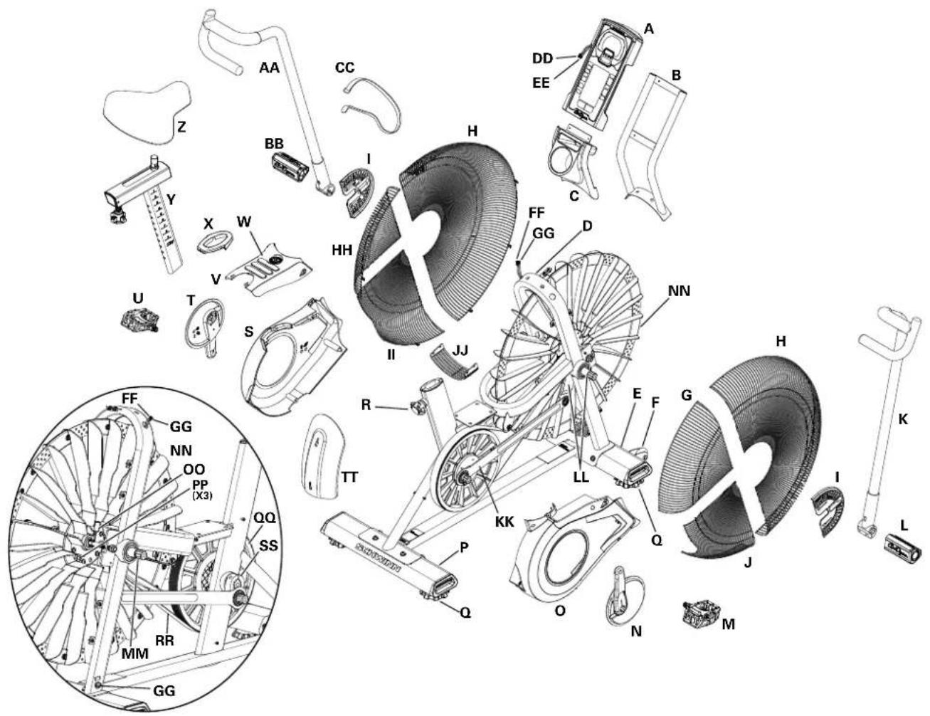
| A | Console | Q | Leveler | GG | Power Inlet Assembly |
| B | Console Mast | R | Seat Adjustment Knob | HH | Fan Cage, Upper Left |
| C | Water Bottle Holder | S | Shroud, Left | II | Fan Cage, Lower Left |
| D | Frame | T | Crank Arm, Left | JJ | Fan Cage, Lower Filler |
| E | Stabilizer, Front | U | Pedal, Left | KK | Linkage Arm |
| F | Transport Wheel | V | Shroud, Top | LL | Arm Pivot, Right |
| G | Fan Cage, Upper Right | W | Foot Step Pad | MM | Arm Pivot, Left |
| H | Fan Cage, Front | X | Grommet | NN | Resistance Fan Assembly |
| I | Fan Cage Side Cover | Y | Seat Post | OO | RPM (Speed) Sensor Assembly |
| J | Fan Cage, Lower Right | Z | Seat | PP | Speed Sensor Magnets |
| K | Handlebar, Right | AA | Handlebar, Left | Drive Pulley | |
| L | Foot Peg, Right | BB | Foot Peg, Left | RR | Drive Belt |
| M | Pedal, Right | CC | Strap, Transport/Immobilization | SS | Crank Link Assembly |
| N | Crank Arm, Right | DD | Data Cable, Upper | TT | AirDyne® Air Diverter |
| O | Shroud, Right | EE | Power Wire, Upper | ||
| P | Stabilizer, Rear | FF | Data Cable, Lower |
natural_image
Technical line drawing of a mechanical assembly with a circular detail highlighting a small component (no text or symbols present)WARNING
HAUPTKOMPONENTEN ENTHALTEN
MONTAGE
MONTAGE
natural_image
Line drawing of an exercise bike with visible wheel, wheels, and attached cable (no text or symbols)BEVOR SIE BEGINNEN
Bewegen des Geräts

natural_image
Diagram of a person using an exercise bike with a close-up inset showing internal components (no text or symbols)
10. Kumulative Messwerte
natural_image
Technical diagram of a mechanical device with directional arrows indicating rotation or movement (no text or symbols present)natural_image
Technical line drawing of an exercise bike with labeled components and a close-up inset showing the wheel assembly (no text or symbols present)KONSOLEN-SERVICE-MODUS
natural_image
Technical line drawing of a mechanical assembly with a circular detail highlighting a component (no text or symbols present)
WAARSCHUWING
https://global.schwinnfitness.com/en/manuals.html
GARANTIE
MEEGELEVERDE HOOFDONDERDELEN
MONTAAGE
MONTAAGE
natural_image
Line drawing of a stationary exercise bike with visible wheel, wheels, and sensor components (no text or symbols)VOORDAT U BEGINT
natural_image
Diagram of a stationary bike with a person standing beside it, showing internal components and a close-up inset (no text or symbols)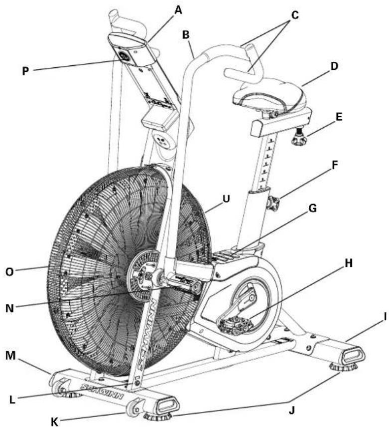

| A | Console | H | Pedalen | O | Luchtweerstandsventilator |
| B | Handvat | I | Achterste stabilisator | P | Batterijcompartiment |
| C | Handgreep | J | Nivelleerder | Q | Telemetrie Hartslag (HR) Ontvanger |
| D | Zadel | K | Transportwiel | R | Mediapplatform |
| E | Zadelverstelknop | L | Voedingsconnector | S | Waterfleshouder |
| F | Zadelpenverstellingsknop | M | Voorste stabilisator | T | Transport- en Immobilisatieriem |
| G | Voetsteunpad | N | Voetsteun | U | AirDyne® Luchtgeleider |
CONSOLEBEDIENING
Console Kenmerken
natural_image
Technical line drawing of an exercise bike with labeled components and a close-up inset showing the wheel assembly (no text or symbols present)Auto Uitschakeling (Slaapstand)
natural_image
Technical line drawing of a mechanical device with a circular component and a curved arrow indicating direction (no text or symbols)
ONDERHOUD ONDERDELEN
natural_image
Technical line drawing of a mechanical assembly with a circular detail highlighting a component (no text or symbols)
AVERTISSEMENT
ASSEMBLAGE
ASSEMBLAGE
www.SchwinnFitness.com/powersupply
natural_image
Line drawing of a stationary exercise bike with visible wheel, wheels, and sensor components (no text or symbols)natural_image
Diagram of a person using an exercise bike with a close-up inset showing internal components (no text or symbols)natural_image
Line drawing of an exercise bike with overhead gear and a close-up inset showing the wheel assembly (no text or symbols)CARACTÉRISTIQUES


natural_image
Diagram of a mechanical device with rotating components and directional arrows indicating motion (no text or symbols)natural_image
Technical line drawing of an exercise bike with labeled components and a close-up inset showing the wheel assembly (no text or symbols present)Pièces d'entretien
natural_image
Technical line drawing of a mechanical assembly with a circular detail highlighting a component (no text or symbols present)
ATTENZIONE
https://global.schwinnfitness.com/it/manuals.html
GARANZIE
PARTI PRINCIPALI INCLUSE
MONTAGGIO
MONTAGGIO
natural_image
Line drawing of a stationary exercise bike with visible wheel, wheels, and battery (no text or symbols)PRIMA DI INIZIARE
natural_image
Diagram of a person using an exercise bike with a close-up inset showing the wheel assembly (no text or symbols)natural_image
Technical line drawing of an exercise bike with labeled components and motion arrows (no text or symbols)
natural_image
Technical diagram of a mechanical device with rotational arrows indicating motion (no text or symbols)Uso della cyclette

natural_image
Technical line drawing of an exercise bike with labeled components and a close-up inset showing the wheel assembly (no text or symbols present)natural_image
Technical line drawing of a mechanical device with a circular component and a curved arrow indicating direction (no text or symbols)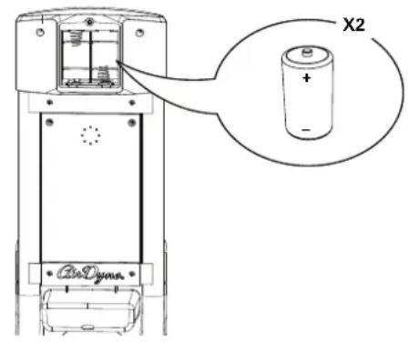

natural_image
Technical line drawing of a mechanical assembly with a circular detail highlighting a component (no text or symbols present)https://global.schwinnfitness.com/en/manuals.html
GARANTÍA
MONTAJE
MONTAJE
www.SchwinnFitness.com/powersupply
O bien, llame al 1 (800) 605–3369.
natural_image
Line drawing of a stationary exercise bike with visible wheels and attached sensors (no text or symbols)ANTES DE COMENZAR
natural_image
Diagram of a person using an exercise bike with a close-up inset showing internal components (no text or symbols)natural_image
Line drawing of an exercise bike with overhead control panel and mechanical components, showing motion arrows (no text or symbols)CARACTERÍSTICAS


natural_image
Mechanical device with rotating components and directional arrows indicating motion (no text or symbols)FUNCIONAMIENTO
natural_image
Technical line drawing of an exercise bike with labeled components and a close-up inset showing the wheel assembly (no text or symbols present)natural_image
Technical line drawing of a mechanical assembly with a circular detail and a labeled component (no text or symbols)
AVISO
PRINCIPAIS PEÇAS INCLUÍDAS
MONTAGEM
MONTAGEM
6. Fixar o selim ao poste do selim
7. Instalar as pilhas na console
natural_image
Line drawing of an exercise bike with visible wheel, wheels, and attached cable (no text or symbols)ANTES DE COMEÇAR
Movendo a Máquina

natural_image
Diagram of a stationary bike with a person standing beside it, showing internal components and a close-up inset (no text or symbols)Nivelando a Máquina
natural_image
Line drawing of an exercise bike with a close-up inset showing the wheel and gear mechanism (no text or symbols)
natural_image
Technical diagram of a mechanical device with rotational arrows indicating motion (no text or symbols)Usando a Máquina

natural_image
Technical line drawing of an exercise bike with labeled components and a close-up inset showing the wheel assembly (no text or symbols present)natural_image
Technical line drawing of a mechanical device with a dial and cable, no visible text or symbols
PEÇAS DE MANUTENÇÃO

natural_image
Technical line drawing of a mechanical assembly with a circular detail highlighting a component (no text or symbols present)natural_image
Line drawing of an exercise bike with visible wheel, arm, and head (no text or symbols)محول طاقة اختياري
www.SchwinnFitness.com/powersupply
natural_image
Diagram of a person using an exercise bike with a close-up inset showing internal components (no text or symbols)natural_image
Technical line drawing of an exercise bike with labeled components and motion arrows (no text or symbols)
line
| Age Group | Methyl Status (Individuals) | |---|---| | 20-24 | 196 | | 25-29 | 191 | | 30-34 | 186 | | 35-39 | 181 | | 40-44 | 176 | | 45- | 171 | | 50-54 | 166 | | 55-59 | 161 | | 60-64 | 156 | | 65-69 | 151 | | 70+ | 146 | | Total | 167 | | Total | 162 | | Total | 158 | | Total | 154 | | Total | 150 | | Total | 145 | | Total | 141 | | Total | 137 | | Total | 133 | | Total | 128 | | Total | 126 | | Total | 118 | | Total | 115 | | Total | 112 | | Total | 109 | | Total | 106 | | Total | 103 | | Total | 100 | | Total | 97 | | Total | 94 | | Total | 91 | | Total | 88 |العمر

natural_image
Technical diagram of a mechanical device with directional arrows indicating motion or rotation (no text or symbols)ضبط المqed
natural_image
Technical line drawing of an exercise bike with labeled components and a close-up inset showing the wheel assembly (no text or symbols present)Console Idle Mode ( Portuguese) Idle Mode ( Portuguese) Idle Mode ( Portuguese) Stop/RESET ( Portuguese) STOP/RESET ( Portuguese) Service Mode ( Portuguese).
2 ات الجهاز:
الإمانيات للا تكون STUDAIAT مزامعات ابنازيا Agricultural Agricultural Agricultural Agricultural Agricultural Agricultural Agricultural Agricultural Agricultural Agricultural Agricultural Agricultural Agricultural Agricultural Agricultural Agricultural Agricultural Agricultural Agricultural Agricultural Agricultural Agricultural Agricultural Agricultural Agricultural Agricultural Agricultural Agricultural Agricultural Agricultural Agricultural Agricultural Agricultural Agricultural Agricultural Agricultural Agricultural Agricultural Agricultural Agricultural Agricultural Agricultural Agricultural Agricultural Agricultural Agricultural Agricultural Agricultural Agricultural Agricultural Agricultural Agricultural Agricultural Agricultural Agricultural Agricultural Agricultural Agricultural Agricultural Agricultural Agricultural Agricultural Agricultural Agricultural Agricultural Agricultural Agricultural Agricultural Agricultural Agricultural Agricultural Agricultural Agricultural Agricultural Agricultural Agricultural Agricultural Agricultural Agricultural Agricultural Agricultural Agricultural Agricultural Agricultural Agricultural Agricultural Agricultural Agricultural Agricultural Agricultural Agricultural Agricultural Agricultural Agricultural Agricultural Agricultural Agricultural Agricultural Agricultural Agricultural Historical and Administrative Management, 2017.
(1) (2) Battery Indicator (مؤشر Laboratories) (1) Battery Indicator (2) Battery Indicator (3) Battery Indicator (4) Battery Indicator (5) Battery Indicator (6) Battery Indicator (7) Battery Indicator (8) Battery Indicator (9) Battery Indicator (10) Battery Indicator (11) Battery Indicator (12) Battery Indicator (13) Battery Indicator (14) Battery Indicator (15) Battery Indicator (16) Battery Indicator (17) Battery Indicator (18) Battery Indicator (19) Battery Indicator (20) Battery Indicator (21) Battery Indicator (22) Battery Indicator (23) Battery Indicator (24) Battery Indicator (25) Battery Indicator (26) Battery Indicator (27) Battery Indicator (28) Battery Indicator (29) Battery Indicator (30) Battery Indicator (31) Battery Indicator (32) Battery Indicator (33) Battery Indicator (34) Battery Indicator (35) Battery Indicator (36) Battery Indicator (37) Battery Indicator (38) Battery Indicator (39) Battery Indicator (40) Battery Indicator (41) Battery Indicator (42) Battery Indicator (43) Battery Indicator (44) Battery Indicator (45) Battery Indicator (46) Battery Indicator (47) Battery Indicator (48) Battery Indicator (49) Battery Indicator (50) Battery Indicator (51) Battery Indicator (52) Battery Indicator (53) Battery Indicator (54) Battery Indicator (55) Battery Indicator (56) Battery Indicator (57) Battery Indicator (58) Battery Indicator (59) Battery Indicator (60) Battery Indicator (61) Battery Indicator (62) Battery Indicator (63) Battery Indicator (64) Battery Indicator (65) Battery Indicator (66) Battery Indicator (67) Battery Indicator (68) Battery Indicator (69) Battery Indicator (70) Battery Indicator (71) Battery Indicator (72) Battery Indicator (73) Battery Indicator (74) Battery Indicator (75) Battery Indicator (76) Battery Indicator (77) Battery Indicator (78) Battery Indicator (79) Battery Indicator (80) Battery Indicator (81) Battery Indicator (82) Battery Indicator (83) Battery Indicator (84) Battery Indicator (85) Battery Indicator (86) Battery Indicator (87) Battery Indicator (88) Battery Indicator (89) Battery Indicator (90) Battery Indicator (91) Battery Indicator (92) Battery Indicator (93) Battery Indicator (94) Battery Indicator (95) Battery Indicator (96) Battery Indicator (97) Battery Indicator (98) Battery Indicator (99) Battery Indicator (100) Battery Indicator 1.


natural_image
Technical line drawing of a mechanical assembly with a magnified inset showing a small component (no text or symbols)
注意
主要零件清單
組裝步驟
組裝步驟
www.SchwinnFitness.com/powersupply
natural_image
Line drawing of a stationary exercise bike with visible wheel, wheels, and battery (no text or symbols)開始前的準備工作
移動機器

natural_image
Diagram of a stationary bike with a person standing beside it, showing internal components and a close-up inset (no text or symbols)調整設備平衡
功能

natural_image
Technical diagram of a mechanical device with rotating components and directional arrows indicating motion (no text or symbols)使用設備

natural_image
Technical line drawing of an exercise bike with labeled components and a close-up inset showing the wheel assembly (no text or symbols present)自動關機(休眠模式)

維護零件
- WARNING
- DANGER!
- WARRANTY
- NEED HELP?
- MAIN PARTS INCLUDEED
- PRE ASSEMBLY
- UNPACKING
- ASSEMBLY
- Attach Stabilizers to Frame Assembly
- Attach Pedals to Frame Assembly
- Connect Cables and Attach the Console/Mast Assembly to Frame Assembly
- Attach Handlebar Arms to Frame Assembly
- Assemble Foot Pegs and Hardware, and Attach Foot Pegs to Frame Assembly
- Attach Seat to Seat Post
- Install Batteries in Console
- Final Inspection
- Optional Power Adapter
- BEFORE YOU START
- Moving the Machine
- Leveling the Machine
- CONSOLE OPERATION
- Console Features
- Programs
- PROGRAM DATA DISPLAY
- Tachometer Display
- TIME
- ROUND
- TIME/INTERVAL area
- PRESS ▲/▼ TO ADJUST
- Cumulative metrics
- Battery indicator
- Volume
- HEART RATE area
- KEYPAD FUNCTIONS
- Remote Heart Rate Monitor
- Heart Rate Calculations
- Auto-Calibration
- OPERATION
- What to Wear
- How Often Should You Exercise
- Seat Adjustment
- Using the Machine
- Locking the Fan Assembly / Storage
- To lock the Fan Assembly:
- Power-Up / Idle Mode
- Auto Shut-Off (Sleep Mode)
- Manual Workout
- 20/10 Interval Workout
- Time Target Workout
- Calories Target Workout
- Kilojoules (kJ) Target Workout
- Miles Target Workout
- Kilometers Target Workout
- Heart Rate Zones
- Pausing / Results Mode
- CONSOLE SERVICE MODE
- MAINTENANCE
- Replacing the Console Batteries
- HAUPTKOMPONENTEN ENTHALTEN
- MONTAGE
- BEVOR SIE BEGINNEN
- Bewegen des Geräts
- Kumulative Messwerte
- KONSOLEN-SERVICE-MODUS
- WAARSCHUWING
- GARANTIE
- MEEGELEVERDE HOOFDONDERDELEN
- MONTAAGE
- VOORDAT U BEGINT
- CONSOLEBEDIENING
- Console Kenmerken
- Auto Uitschakeling (Slaapstand)
- ONDERHOUD ONDERDELEN
- AVERTISSEMENT
- ASSEMBLAGE
- CARACTÉRISTIQUES
- Pièces d'entretien
- ATTENZIONE
- GARANZIE
- PARTI PRINCIPALI INCLUSE
- MONTAGGIO
- PRIMA DI INIZIARE
- Uso della cyclette
- GARANTÍA
- MONTAJE
- ANTES DE COMENZAR
- CARACTERÍSTICAS
- FUNCIONAMIENTO
- AVISO
- PRINCIPAIS PEÇAS INCLUÍDAS
- MONTAGEM
- Fixar o selim ao poste do selim
- Instalar as pilhas na console
- ANTES DE COMEÇAR
- Movendo a Máquina
- Nivelando a Máquina
- Usando a Máquina
- PEÇAS DE MANUTENÇÃO
- ضبط المqed
- 注意
- 主要零件清單
- 組裝步驟
- 開始前的準備工作
- 移動機器
- 調整設備平衡
- 功能
- 使用設備
- 自動關機(休眠模式)
- 維護零件
Brand : Schwinn
Model : Airdyne AD8
Category : Fitness Equipment