
SBCVL1400 - Headphones PHILIPS - Free user manual and instructions
Find the device manual for free SBCVL1400 PHILIPS in PDF.

| Product type | Wireless TV link (transmitter/receiver set) |
| Transmitter dimensions | 270 mm (W) × 146 mm (D) × 61 mm (H) |
| Receiver dimensions | Not specified in the manual |
| Power supply | 220-240 V AC / 50 Hz via power adapter (12 V DC / 500 mA) |
| Power consumption in operation | 6 W (transmitter and receiver combined) |
| Number of video inputs | 4 (Scart connectors) |
| Scart connectors (1 & 2) | Stereo audio/video input: CVBS |
| Scart connector (3) | Stereo audio/video input: RGB & CVBS |
| Scart connector (4) | Stereo audio/video input: RGB & CVBS |
| Scart output connector (transmitter) | Stereo audio/video output: CVBS, compatible with P50 |
| Scart output connector (receiver) | Stereo audio/video output: CVBS |
| RCA audio output connector | Yes (on transmitter) |
| Supported video standards | PAL / NTSC / SECAM |
| Effective range | Up to 100 m outdoors, about 30 m indoors (depending on obstacles) |
| Carrier frequency | 2.4 GHz |
| Number of channels | 4 (may vary according to local regulations) |
| Modulation type | FM |
| Transmission power | < 10 mW |
| Remote control transmission | Carrier frequency 433.92 MHz, AM modulation, power < 10 mW, range up to 6 m |
| Remote control extension cord | Yes, with 4 IR cells |
| Antennas | Integrated (at the back of both units) |
| Video copy function | Yes, via COPY SOURCE button and Scart connector 4 |
| Universal remote control | Included, can control up to 5 devices |
| Safety | Do not expose to moisture or excessive heat, do not open, use adapters compliant with EN60950 |
| Maintenance and cleaning | Not specified; avoid any liquid |
| Spare parts and repairability | Not specified; contact Philips dealer in case of problem |
Frequently Asked Questions - SBCVL1400 PHILIPS
User questions about SBCVL1400 PHILIPS
0 question about this device. Answer the ones you know or ask your own.
Ask a new question about this device
Download the instructions for your Headphones in PDF format for free! Find your manual SBCVL1400 - PHILIPS and take your electronic device back in hand. On this page are published all the documents necessary for the use of your device. SBCVL1400 by PHILIPS.
USER MANUAL SBCVL1400 PHILIPS
The Philips Wireless TV Link allows you to distribute any kind of video signal (digital or analogue set-top boxes, DVDs, satellite receivers, VCRs etc.) or cable programmes throughout your house without the need for extra wiring, running cables or drilling holes. This means that you can enjoy the freedom of watching Pay-TV on your bedroom TV. You can also enjoy a film playing on your living-room video recorder while others independently watch their favourite programmes on the main TV.
Besides distributing video signals wirelessly, the Wireless TV Link also functions as a switch box for your main TV. It is equipped with four SCART input connectors. These allow you to connect up to four video devices at the same time, so cable swapping or re-configuring your audio/video set-up is no longer necessary. In addition, three of the SCART inputs can be linked to the fourth one, which makes copying your video content very simple.
The universal remote control allows you to control the Wireless TV Link, your second TV and up to four video sources, regardless of brand. You don't have to carry around the other remote control units!
The Wireless TV Link is based on wireless RF technology that offers you in-home convenience. To enable you to enjoy the best possible performance, four transmission channels are provided so you can select the channel that provides optimum viewing with the minimum of interference.
Pure wireless home convenience!
Safety precautions
Please read this guide carefully and keep it for future reference.
- Do not use this product in moist places or close to water.
- Do not expose this product to extreme heat.
- Do not open this product; in case of technical difficulties bring it to your Philips retailer.
- Do not cover this product.
- Only connect the AC power adapters to a power supply of 220-240 VAC / 50Hz.
- Only use the AC power adapters included or a type that complies with safety standard EN60950 and that has the following specification: 12 Volt DC / 500mA.
- Inadequately protected or sensitive electronic equipment may be affected by the use of this product. This interference can lead to damage to either equipment. Please check whether or not surrounding equipment can be affected by this product before you start using it.
Keys and functions
Product illustration on inside flap:
A Transmitter Unit
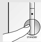
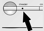
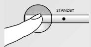
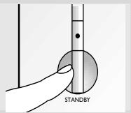
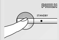
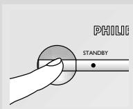
1 Power button
switches the transmitter between stand-by and on.
2 Power light
red in stand-by mode, green when power is on, flashes when receiving remote control commands
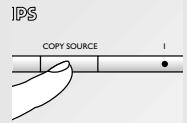
3 COPY SOURCE button
links SCART input 1,2,3 or SCART OUT to SCART in/output 4.
4 Copy source indication lights
indicate which SCART input (1,2 or 3) is linked to SCART in/output 4. When there is no light indication the SCART OUT is linked to SCART in/output 4.
5 VIEW SOURCE button
selects which SCART input (1-4) is viewed on the transmitter SCART output
6 View source indication display
indicates the SCART input number that is viewed on the transmitter output.
7 AUTO light
indicates if automatic SCART switching is enabled (on) or disabled (off).
8 Infra-red remote control blaster lights
transmit infra-red remote control signals from the receiver to the video source devices below.
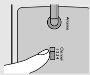
9 Transmission channel switch
switches the frequency channel of the audio/video signal to minimize interference.
10 SCART input (1-4) connectors
connect SCART-enabled video source devices to these connectors
SCART output connector
connect to the main TV
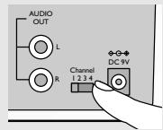
12 RCA sound output connector
connect to an audio amplifier
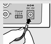
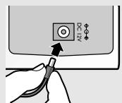
13 DC power input
14 Remote control blaster cord connector
15 Remote control blaster cord
four infra-red lights used instead of the infra-red remote control blaster lights (A-8) for a more precise control of the video sources.
16 SCART cable
17 Power adapter
18 Remote control antenna
| Keys and functions | |
| Product illustration on inside flap: | B Receiver Unit 19 Power button switches the receiver between stand-by and on. When the receiver unit is turned on or off the transmitter unit is automatically turned on or off as well. 20 Power light red in stand-by mode, green when power is on, flashes when receiving remote control commands 21 Remote control signal receiver receives remote control commands which are sent to the transmitter unit to control the video sources. 22 Input source up (+) / down (-) buttons selects one of the four video sources connected to the transmitter unit for viewing on the second TV. 23 Transmission channel switch switches the frequency channel of the audio/video signal to minimize interference. 24 SCART output connector connect to the second TV 25 DC power input 26 SCART cable 27 Power adapter 28 Remote control antenna |
| Important information | |
| Each video source, the main TV and the second TV must have SCART connectors. Two SCART cables are supplied; you will require additional SCART cables for the video sources you connect. A video source can be any satellite receiver, Pay-TV decoder box (digital or analogue), video recorder (VCR), DVD player, camcorder, game console etc. Before using the Universal Remote Control it must be set up to operate with your other equipment. Refer to its instructions for use to discover the full potential of this versatile unit. In this guide we call the main TV (connected to the transmitter unit) TV1; we call the second TV (connected to the receiver unit) TV2. It may be helpful to have the instructions for use for the TVs and the video sources at hand for reference. | |
Getting your Wireless TV Link ready
Setting up the transmitter unit
1 Set channel selection switch to channel I. Always set transmitter and receiver units to the same channel.
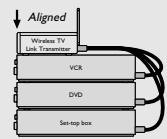
2 Position transmitter unit on top of video sources with the front panels aligned vertically. Never put video sources or metal plates on top of the transmitter unit.
3 Connect SCART cables from video sources to transmitter unit SCART inputs.
4 Connect SCART cable from transmitter unit output to TVI.
5 Connect power adapter to transmitter unit.
6 Plug power adapter into mains socket.
Setting up the receiver unit
1 Set channel selection switch to channel I. Always set transmitter and receiver units to the same channel.
2 Position the receiver unit close to TV2. Ensure that the front of the receiver unit is positioned to receive remote control commands.
3 Connect SCART cable from receiver unit to TV2.
4 Connect second power adapter to receiver unit.
5 Plug second power adapter into mains socket.
PHILIP
Checking the remote control operation
1 Switch on TV2 and the receiver unit.
Make sure your transmitter is also turned on.
2 Point the video source's remote control unit at the receiver unit and switch between play and stop.
The power light (B-19) on the receiver unit flashes to show that it has received the remote control command.
3 Have a second person check that the power light (A-1) on the transmitter unit flashes.
This indicates that it is receiving the remote control signal from the receiver unit.
4 If the power light (A-1) does not flash, reposition the remote control antenna at the rear of either unit (A-18 or B-28).
The power light on the transmitter unit should now flash when a remote control command is given at the receiver side.
5 If the video source does not respond to the remote command, try realigning the front of the transmitter unit with the front of the video source until you get a response.
6 If the video source still fails to respond install the remote control blaster cord as described below.
Installing the remote control blaster cord
1 Switch off the transmitter unit.
2 Plug the blaster cord (A-15) into the IR socket (A-11) at the back of the transmitter unit.
3 Switch on both transmitter and receiver units.
4 Ask another person to press and hold a key of the video source's remote control while pointing it at the receiver unit.
5 While the other person is doing this, slowly move an IR light (a black block) along the front panel of the video source.
Do not let the distance between the IR light and the front panel exceed 1 cm. When the video source reacts to the command from the remote control, the correct position has been found. (Alternatively, locate the IR sensor by referring to the video source's instructions for use.)
6 Remove the adhesive tape from the back of the IR light and stick it onto the IR sensor window of the video source.
7 If necessary, repeat this procedure for the other video sources.
Using the wireless link with TV2
Watching and controlling video sources on TV2
1 Switch on TV2.
It is not necessary to switch on TVI to enjoy video programmes on TV2.
2 Press the power button (B-19) to switch on the receiver unit (or use the universal remote control unit*).
When the receiver unit is turned on, the transmitter unit switches on automatically and TV2 displays the signal on its SCART input.
3 Press the - or + buttons (B-22) on the receiver unit to select the video source to be displayed (or use the universal remote control unit*).
The selection cycle is SCART input 1 > 2 > 3 > 4
4 Aim the remote control at the receiver unit to control the video source.
Use either video source's remote control or, even better, the universal remote control after selecting the correct mode*.
Watching cable programmes on TV2
1 Switch on the VCR (or DVD+RW).
The VCR (or DVD+RW) must be connected to the cable TV network and to the transmitter unit of the Wireless TV Link.
Some VCRs need to be switched to tuner mode to remain on (refer to their instructions for use).
Simultaneously recording a cable programme on the VCR and wirelessly watching cable programmes on TV2 is not possible.
2 Switch on TV2.
It is not necessary to switch on TVI to enjoy cables programmes on TV2.
3 Press the power button (B-19) to switch on the receiver unit (or use the universal remote control unit*).
When the receiver unit is turned on, the transmitter unit switches on automatically and TV2 displays the signal on its SCART input.
4 Press the - or + buttons (B-22) on the receiver unit to select the VCR (or DVD+RW) as the video source (or use the universal remote control unit*).
5 Aim the remote control at the receiver unit and press a numbered (or up/down) button to select the cable programme on the VCR (or DVD+RW).
Use either video source's remote control or, even better, the universal remote control after selecting the correct mode*.
Using the wireless link with TVI
Selecting the video source automatically
1 Press power button (A-1) to switch transmitter unit to stand-by. Power light (A-2) is red; AUTO light (A-7) is on (automatic switching is enabled).
2 Switch on TVI.
3 Switch on the video source.
TVI switches automatically to the corresponding external input and displays the activated video source.
4 Operatethevideo source.
If another video source is activated, TVI displays that video source. The last activated video source is displayed.
Selecting the video source manually
1 Press power button (A-1) to switch transmitter unit on.
Power light (A-2) is green; AUTO light (A-7) is off (automatic switching is disabled).
Switching on the receiver unit automatically switches on the transmitter unit.
2 Switch on TVI.
3 Select the EXT or AV input of TVI to which the transmitter unit is connected (see TV instruction manual).
4 Press VIEW SOURCE button (A-5) to select one of the four SCART inputs. The selection cycle is SCART input 1 > 2 > 3 > 4 > AUTO. The indication display (A-6) displays the number of the selected video source.
5 Switch on and operate the video source.
When the transmitter is turned on, AUTO mode is automatically disabled and the last viewed video source remains displayed. Automatic SCART switching (automatic input selection) of TV1 is turned off when the transmitter unit is turned on.
Using additional features
Linking video sources
1 Connect a VCR (or DVD+RW) to SCART in/output 4 Use a full-wired SCART cable only for this connection.
2 Connect at least one video source to SCART input 1, 2 or 3.
3 Press the COPY SOURCE button (A-3) to select the SCART input to be copied to SCART output 4. The selected SCART input 1, 2 or 3 lights up (A-4).
4 Select EXT or AV input of the VCR (or DVD+RW). Check that the correct video source is selected.
5 Press the record button on the VCR (or DVD+RW).
6 Press the play button on the video source The video source is now copied to the VCR (or DVD+RW).
When copying from a digital medium (DVD), only the audio/video is copied. Additional DVD features (language selection, etc.) are not copied. When the copy function is disabled, the programme on TVI, if on, is recorded. Please note that some video sources are copy-protected.
Using the Universal Remote Control
The Universal Remote Control is capable of controlling the receiver or transmitter unit and up to five additional devices. With this single unit you can control all your devices remotely, regardless of their brand.
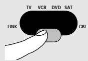
1 Select the LINK mode with the mode selector to operate the receiver or transmitter unit remotely. The red indicator under LINK lights up. The LINK mode does not require any form of set-up and can be used straight away.
2 Point the universal remote control at the transmitter unit and press the channel up/down or numerical keys 1 to 4 to select the SCART input for viewing on TVI. Pressing the power button turns the transmitter on or off.
3 Point the universal remote control at the receiver unit and press the channel up/ down or numerical keys 1 to 4 to select the video source for viewing on TV2. Pressing the power button turns both the transmitter and the receiver on or off.
| Problem solving | |
| Problem | Solution |
| First, check all cables to ensure that they are connected correctly. | |
| No picture on TV2. | Ensure that both units are switched on (A-2 and B-20 are green). |
| Select the EXT or AV channel on TV2. | |
| Activate the video source (set-top box: power on;VCR/DVD: playback). | |
| Select the correct video source on the Receiver unit. | |
| Select the same frequency channel on both the Receiver and Transmitter units. | |
| If a VCR is the video source, ensure that the correct SCART connector of the VCR is used (Ext1 or Ext2 - check VCRs user manual). | |
| Bad picture/ sound quality on TV2. | Move the receiver unit around gently until you get good picture and sound quality. |
| Move the transmitter unit around gently until you get good picture and sound quality. | |
| Change both units to another frequency channel. | |
| Reduce the distance between the transmitter and receiver unit (<30m). | |
| Cable programme on VCR disappears. | Disable the auto standby mode of the VCR. (Check VCR's user manual). |
| Wrong picture on TV2. | Select the EXT or AV channel on TV2. |
| Select another video source on the receiver unit. | |
| Activate the video source (set-top box: power on;VCR/DVD: playback). | |
| Swap the SCART connectors on the transmitter unit. | |
| Switch to another frequency channel on both units. | |
| Wrong picture on TV1. | Select the correct EXT or AV channel on TV1 (see TV instruction manual). |
| Select the correct video source with the VIEW SOURCE button (A-5). | |
| Select a regular programme number. | |
| Problem solving | |
| Problem | Solution |
| No control of video sources from TV2. | Aim the remote control directly at the receiver unit and ensure that there are no obstacles in between (B-19 must flash). |
| Ensure that there is no other wireless device (wireless headphones, speakers, RF control signals) interfering with the remote control. | |
| The maximum operating distance between the remote control and the receiver unit is 6 metres*; be sure you are within this range. | |
| Ensure that the transmitter and receiver unit are more than 5 metres apart. | |
| Ensure that the remote control belonging to the video source is used to contro itl. | |
| Reposition the remote control blaster cord light on the video source, or place the light 5-10 cm in front of the video source. | |
| Buzzing sound when using the remote control . | Move the receiver unit around gently until the buzzing sound stops. |
| Move the transmitter unit around gently until the buzzing sound stops. | |
| With some types of TV you will not be able to solve this problem. | |
| Easylink feature doesn't work. | Check that both your TV and VCR support this feature (check TV and VCRs user manuals). |
| Use Easylink compatible or fully wired SCART cables. | |
| S-VHS video gives black and white pictures only. | Select CVBS video output format for your S-VHS VCR when using SCART input 1 or 2 (check the VCRs user manual). |
| DVD player gives no pictures on either TVI or TV2. | Connect the DVD player to SCART input 3 or 4 (both support RGB). |
| Select CVBS video output format for your DVD player (check the DVD player's user manual). | |
- depends on remote control's signal strength and battery condition.
General notes
- Picture and sound quality is influenced by the use of microwave ovens. Other wireless systems (Bluetooth, wireless LANs, etc.) can also adversely influence the quality of picture and sound, and vice versa.
- The Wireless TV Link is a Radio Frequency (RF) based product. As such its performance can suffer the same kinds of interference as GSMs, portable radios and other RF-based products.
- If the same video source is selected for both TVs, then you get the same programme on each TV.
- The Wireless TV link is not limited to just one room or house. You can use it anywhere in or around the house. Consequently, anybody in the vicinity of your house (up to the maximum operating range) who also owns a Wireless TV link set to the same channel, can watch the same programmes that are playing on your video source.
- In order to prevent the mixing of remote control commands it is not advisable to use a TV as a video source.
- Some built-in VCRs (TV-VCR combination) cannot be used with the transmitter unit (depends on brand and type).
- Video sources cannot be controlled remotely if the carrier frequency of the IR signal is outside the operation window of 32kHz to 57kHz .
- The transmitter unit can support the channel downloading feature (also known as 'Follow-TV', 'Easylink', 'SmartLink', 'AV-Link', 'MEGALoic', 'TV-Link' or 'Q-Link') of high-end TVs and VCRs. Fully wired SCART cables that support this feature must be used.
- Radio wave safety: When switched on, the Philips Wireless TV Link transmits and receives radio waves. The Philips Wireless TV Link complies with the standards that are defined for it.
- The Philips Wireless TV Link has an operating range of up to 100 metres in open air. Walls, ceilings and other large objects may limit the useable operating range to about 30 metres in the house.
Technical specifications
General
Power supply:
Operating
consumption:
Number of input devices:
220-240VAC/50Hz
- 6 W (both transmitter and receiver unit)
4
Transmitter unit
Dimensions:
SCART1&2
connectors:
SCART 3 connector:
SCART 4 connector:
270 (W) × 146 (D) × 61 (H) mm
Input: stereo audio / video: CVBS.
Input: stereo audio / video: RGB&CVBS
Input: stereo audio / video: RGB&CVBS
Output: stereo audio / video: CVBS, P50 compatible
- Input: stereo audio / video: CVBS
Output: stereo audio / video: RGB&CVBS P50 compatible
SCART output
connector:
Receiver unit
Dimensions:
SCART connector:
Video standards
supported:
Operating range:
61 (W) × 146 (D) × 150 (H) mm
Output: stereo audio / video: CVBS
PAL/NTSC/SECAM
- Up to 100m in open air; up to 30m in house
Audio / Video
transmission
Carrier frequency:
Number of channels:
Type of modulation:
Transmission power:
2.4 GHz
4 (may be less, depending on local regulations)
FM
- <10mW
Remote Control
transmission
Antennas:
Carrier frequency:
Type of modulation:
Transmission power:
Range of IR reception:
Carrier frequency:
Remote control blaster cord:
Remote control
antenna:
Built-in
433.92 MHz
AM
- <10mW
Up to 6 metres max.
32kHz - 57kHz
Yes, 4 Infrared lights
Antennas at rear of both units
Liaison TV sans fil
SBC VLI400
5 Bouton VIEW SOURCE
61 (L) × 146 (P) × 150 (H) mm
Transmission audio / video
Product illustration on inside flap:
Ligue ao靼o television
25 Entrada de corrente CC
26 Cabo SCART
27 Adaptador de corrente
28 Antena do commando remoto
6 W (para as unidas transmissora e receptora)
4
270 (L) × 146 (P) × 61 (A) mm
61 (L) × 146 (P) × 150 (A) mm
IIapakoo60nogkawokov npoypaumotv OTV TV2
1 AvayrTo VCR (DVD+RW).
- Safety precautions
- Keys and functions
- A Transmitter Unit
- Getting your Wireless TV Link ready
- Setting up the transmitter unit
- Setting up the receiver unit
- Checking the remote control operation
- Installing the remote control blaster cord
- Using the wireless link with TV2
- Watching and controlling video sources on TV2
- Watching cable programmes on TV2
- Using the wireless link with TVI
- Selecting the video source automatically
- Selecting the video source manually
- Using additional features
- Linking video sources
- Using the Universal Remote Control
- General notes
- Technical specifications
- General
- Transmitter unit
- Receiver unit
- Audio / Video
- transmission
- Remote Control
- Liaison TV sans fil
- SBC VLI400
- Transmission audio / video
- IIapakoo60nogkawokov npoypaumotv OTV TV2
Brand : PHILIPS
Model : SBCVL1400
Category : Headphones