
NOX 25 6M - Pump Jardino - Free user manual and instructions
Find the device manual for free NOX 25 6M Jardino in PDF.
| Product type | Single-cell centrifugal pool pump with integrated pre-filter |
| Usage | Filtration and recirculation of pool water (clean water, max temperature 40°C) |
| Power supply | Single-phase 230 V / 50 Hz (or three-phase depending on version – check nameplate) |
| Motor protection | Integrated thermal protection (single-phase) |
| Liquid temperature | 4°C to 40°C |
| Ambient temperature | 0°C to 40°C |
| Storage temperature | -10°C to 50°C |
| Max relative humidity | 95% |
| Priming | Manual – fill pump housing with water before first start-up |
| Installation | On a solid, horizontal base, sheltered from weather, suction at 30 cm below minimum water level |
| Electrical connection | All-pole switch with contact opening ≥ 3 mm, 30 mA differential recommended, mandatory grounding |
| Maintenance | Clean the pre-filter regularly, drain in winter, clean with a damp cloth without aggressive products |
| Safety | Do not run dry, voltage identical to mains, cable H07 RN-F, safety distance of 3.5 m from the pool |
| Spare parts and repairability | Repair exclusively by an authorized technical service (list at www.jardinopool.eu) |
| Standards | CE compliant: Machinery Directive 2006/42/EC, EMC 2014/30/EU, Low Voltage 2014/35/EU, Noise Emission 2000/14/EC, Eco-Design 2009/125/EC |
Frequently Asked Questions - NOX 25 6M Jardino
User questions about NOX 25 6M Jardino
0 question about this device. Answer the ones you know or ask your own.
Ask a new question about this device
Download the instructions for your Pump in PDF format for free! Find your manual NOX 25 6M - Jardino and take your electronic device back in hand. On this page are published all the documents necessary for the use of your device. NOX 25 6M by Jardino.
USER MANUAL NOX 25 6M Jardino
EN: EVIDENCE OF CONFORMITY
We declare, under our responsibility, that the products in this manual comply with the following directives and standards:
- Directive 2006/42/EC (Machine Security): Standard EN 809 and EN 60204-1
- Directive EMC 2014/30/EU (Electromagnetic compatibility): Standard EN 61000-6-1 y EN 61000-6-3
- Directive 2014/35/EU (Low voltage): Standard EN 60335-1 and EN 60335-2-41
- Directive 2000/14/EC (noise emission): EN-ISO 3744
- Directive 2009/125/EC (ecological design): Regulation 640/2009 for three-phase electric motors >0.75kW . Standard EN 60034-30.
- Directive 2011/65/UE(Restriction of hazardous substances): Standard EN 50581.
- Standard EN 16713-2 (See serial number on the nameplate and fig. 4)
FR:DECLARATION DE CONFORMITE
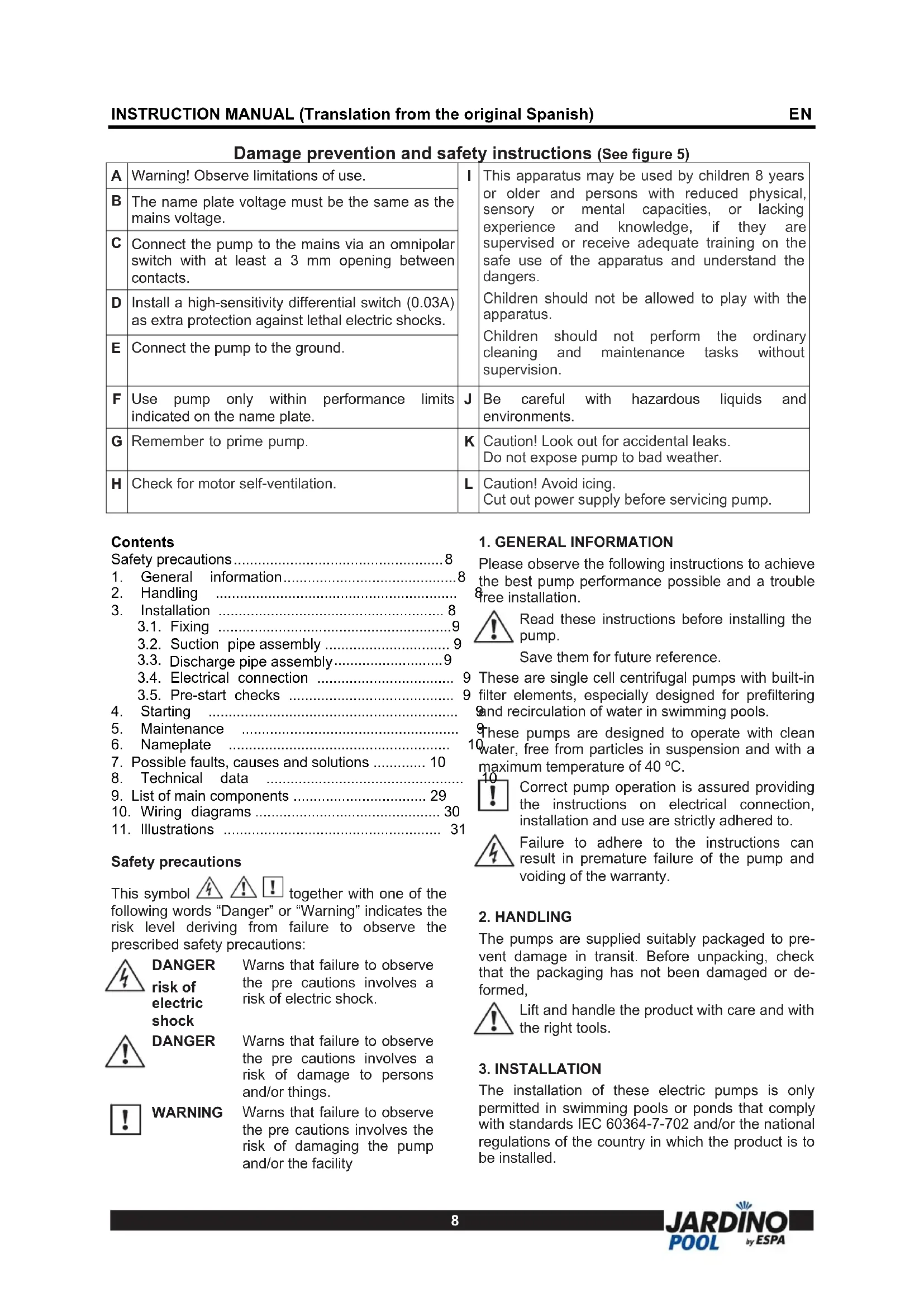
Damage prevention and safety instructions (See figure 5)
| A | Warning! Observe limitations of use. | I | This apparatus may be used by children 8 years or older and persons with reduced physical, sensory or mental capacities, or lacking experience and knowledge, if they are supervised or receive adequate training on the safe use of the apparatus and understand the dangers. |
| B | The name plate voltage must be the same as the mains voltage. | ||
| C | Connect the pump to the mains via an omnipolar switch with at least a 3 mm opening between contacts. | ||
| D | Install a high-sensitivity differential switch (0.03A) as extra protection against lethal electric shocks. | ||
| E | Connect the pump to the ground. | ||
| F | Use pump only within performance limits indicated on the name plate. | J | Be careful with hazardous liquids and environments. |
| G | Remember to prime pump. | K | Caution! Look out for accidental leaks. Do not expose pump to bad weather. |
| H | Check for motor self-ventilation. | L | Caution! Avoid icing. Cut out power supply before servicing pump. |
Contents
Safety precautions. 8
- General information 8
- Handling
- Installation 8
3.1. Fixing 9
3.2. Suction pipe assembly 9
3.3. Discharge pipe assembly.. 9
3.4. Electrical connection
3.5. Pre-start checks
- Starting
- Maintenance
- Nameplate
- Possible faults, causes and solutions 10
- Technical data
9.List of main components 29 - Wiring diagrams 30
- Illustrations 31
Safety precautions
This symbol together with one of the following words "Danger" or "Warning" indicates the risk level deriving from failure to observe the prescribed safety precautions:

DANGER
risk of electric shock

DANGER

WARNING
Warns that failure to observe the precautions involves a risk of electric shock.
Warns that failure to observe the precautions involves a risk of damage to persons and/or things.
Warns that failure to observe the pre cautions involves the risk of damaging the pump and/or the facility
1. GENERAL INFORMATION
Please observe the following instructions to achieve the best pump performance possible and a trouble free installation.

Read these instructions before installing the pump.
Save them for future reference.
9 These are single cell centrifugal pumps with built-in filter elements, especially designed for prefiltering and recirculation of water in swimming pools.
These pumps are designed to operate with clean water, free from particles in suspension and with a maximum temperature of 40^ .

Correct pump operation is assured providing the instructions on electrical connection, installation and use are strictly adhered to.

Failure to adhere to the instructions can result in premature failure of the pump and voiding of the warranty.
2. HANDLING
The pumps are supplied suitably packaged to prevent damage in transit. Before unpacking, check that the packaging has not been damaged or deformed,

Lift and handle the product with care and with the right tools.
3. INSTALLATION
The installation of these electric pumps is only permitted in swimming pools or ponds that comply with standards IEC 60364-7-702 and/or the national regulations of the country in which the product is to be installed.
3.1. Fixing
The pump should be installed on a solid, horizontal base, secured by screws or bolts and using the existing holes in the mount.
The pump should be protected from possible flooding and receive dry ventilation.
3.2. Suction pipe assembly
The pumps must be installed at least two meters from the wall of the pool, and at the same height as the level of the water, or if possible, below. The end of the suction pipe must always remain at least 30cm below the water level.
The suction pipe, if longer than 7 meters, must be of the same or greater diameter than the pump inlet and installed in an upward inclination to prevent trapped air pockets forming.
If the pump is required to perform a suction lift, to avoid unnecessary losses of head on the discharge side, the pump should be installed as close as possible to the water. It is not advisable to install the pump at more than 3m geometrical height from the water level.
3.3. Discharge pipe assembly
It is recommended to use pipes with a diameter equal or greater than the pump outlet. This will reduce loss of head caused by friction in longer pipe runs.
Pipework must be supported and their weight must not rest on the pump.
3.4. Electrical connection

The electrical installation must have a multipole isolator with minimum 3mm contact openings. The protection of the system will be based on a differential switch ( fn = 30mA)
The power cable must correspond at least to the type H07 RN-F (according to 60245 IEC 66) and having terminals.
The connection and its dimensioning must be performed by a qualified installer according to the needs of the facility and following the regulations in force in each country.
The power supply socket for the apparatus must be at least 3.5m from the pool.

Single-phase motors have thermal protection.
All of three phase motor pumps do not incorporate this protection. They must be connected to a motor-protective circuit breaker that can be adjusted manually. Set the circuit breaker according to the current given in the rating plate plus 10% .
Follow instructions given on fig.1 for correct electrical connection.
3.5. Pre-start checks

Ensure the voltage and frequency of the supply corresponds to the values indicated on the electrical data label.
Ensure that the pump shaft is rotating freely.
Fill the pump body with water through the filter cover to the bottom level of the suction line.
Check all joints and connections for leaks.
Set the prefilter cover back in place and screw it to a suitable tightness.
THIS PUMP MUST NEVER BE DRY RUN.
4. STARTING
Ensure all valves in the pipework are open.
Connect power supply. There will be a delay before water appears at the end of the discharge pipe.
Viewings from the fan ensure that the rotation of the motor is clockwise. On three phase pumps the motor may rotate anticlockwise. If this is happening, the flow will be lower than expected. To rectify this situation the two supply phases need to be reversed.
Ensure that the absorbed current is the same or lower than the maximum shown on the name plate. Adjust the thermal relay if is necessary.
If the pump fails to operate refer to the possible faults, causes and solutions list for assistance.
5. MAINTENANCE
Under normal conditions these pumps require no special or planned maintenance.
Clean the pump with a damp cloth without using harsh products.

If the pump is not to be operated for a long period it is recommended to remove it from the installation, drain down and store in a dry, well ventilated place.
ATTENTION: In the event of faults or damage occurring to the pump, repairs should only be carried out by an authorised service agent.
The Official Technical Services list is in http://www.jardinopool.eu.
When the pump is eventually disposed of, please note that it contains no toxic or polluting material. All main components are material identified to allow selective disposal.
6. PLATE SHOWING CHARACTERISTICS
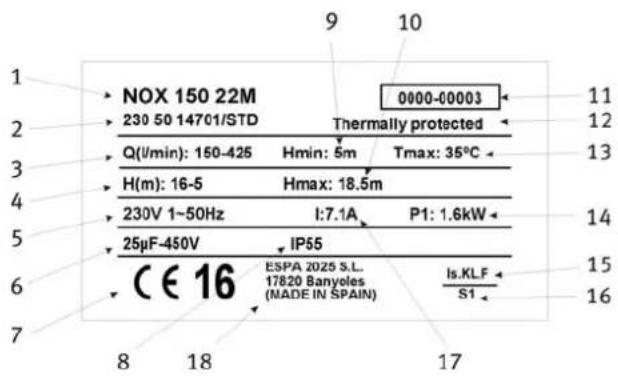
DESCRIPTION
| 1 Item reference |
| 2 Voltage + frequency + item specifications |
| 3 Flow |
| 4 Pressure |
| 5 Nominal voltage, no. stages, alternate current symbol and frequency |
| 6 Capacitor |
| 7 EC mark + year of manufacture |
| 8 Humidity protection level |
| 9 Minimum working pressure |
| 10 Maximum pressure |
| 11 Pump serial no. (Fig.4) |
| 12 Thermal protection incorporated indicator |
| 13 Max. liquid temperature |
| 14 Electric pump unit absorbed power(P1) |
| 15 Designated motor insulation |
| 16 Continuous operation symbol |
| 17 Maximum nominal intensity at nominal voltage |
| 18 Name and address of vendor responsible for the product |
7. POSSIBLE FAULTS, CAUSES AND SOLUTIONS
1) Pump does not prime.
2) Pump supplies scant flow.
3) Pump noisy.
4) Pump does not start.
5) Motor makes sound but does no start.
| 1 | 2 | 3 | 4 | 5 | POSSIBLE PROBLEM | SOLUTIONS |
| X | X | Air entry trough suction line | Verify condition of connectors and gaskets of suction line | |||
| X | Inadequate airtightness of filter cover | Clean the filter cover and verify con- diction of rubber gasket | ||||
| X | X | Motor turning direction reversed Reverse 2 phases of the supply | ||||
| X | Defective mechanical seal Change | mechanical seal | ||||
| X | X | Excessive suction height | Excessive suction height | |||
| X | X | X | Incorrect voltage | Verify the voltage specified on the nameplate and that of the mains | ||
| X | No water in prefilter | Fill prefilter with water | ||||
| X | Suctioning out of water | Set suction in correct position | ||||
| X | Filter clogged | Clean filter | ||||
| X | X | Diameter of suction line smaller than required | Correctly dimension suction line | |||
| X | Discharge clogged | Inspect filter and discharge line | ||||
| X | Incorrect pump attachment | Attach pump correctly | ||||
| X | Foreign body in pump | Clean pump and inspect its filter | ||||
| X | Thermal relay tripped | Reset thermal relay | ||||
| X | Lack of power | Reset the fuses | ||||
| X | Motor blocked | Remove the motor and call the Technical Service | ||||
8. TECHNICAL DATA
Liquid temperature: 4^ - 40^
Ambient temperature: 0^ - 40^
Storage temperature: -10°C - 50°C
Ambient relative humidity, max.: 95%
Motor class I.
Other data see Figure 2.
A Atencion as limitacoes de emprego.
Bo3MOxHocb npaKeHnJIIOe N/INIOBpeKDeHnIpeDMetOB
B03MOxHOCtB NOBpeXeHne Hacoca N/ nIuObOpyDoBaHnA
1.OchOBhpie CBeDeHn
Iyueo HcnoJb3OBAHn Haocca n er0 6e3onacHO Kcnnyataun.
cepna CEHTPO6eKhbIX ODHOCTyneHcyTaBIX HAcOCOB CO BCTPOeHHbIMN fNtPyUcIMM 3JeMeHTaMn. Pa3pa6oTaHbI DJIra 06ecneueHn npedBaPntelbHOOuNCTkN I peunpkyJLaUN BOdbl B baccenHax.
PpeHa3HaueHbI Dnpa 8oToB C uHcToB BoDoN npMakmambHoT TemepaType 40^
! PpOHTaIe BCHO HNCTpyKUHO CTPOCJeDyIte yKa3aHnA M NO yCTaHOBKe NHCNOJIb3OBAHnIO HAcOca.
ObpaTnTe BHNMaHne Ha cxEmbl 3NeKTrpUeCKNX COeINHeHNI.
HecobIIODeHne npaBn MOKeT npuBecTN K nepepy3ke DburaTeN NIN dpyrIM NOBpeXdEHnM 3a KOToPbIE Mbl He MoXeM HecTN OTBeTCTBeHHOCTN.
2. YctaHOBka
3NeKtpoHacoc yctaHOBnTb Ha poBHyo, JcEcTKyIO pNOUAdKy B XOPOwO npOBetpNBaEMOM MecTe, 3aunuHOM OT HeNOrOdbI. Dnra yMeHbWeHnA Wyma n Bn6paunn prn pa6ote KpeNJIeHne K pNOuaAdKe cJeDyeT BblONHnTb yepe3 pe3INHOBbIe Wain6bI n PpOKlaKn.
2.1 Tpy6o npoBOaB1
HacocdoJxeh yctHaabnBaTbcra KaK MoXHO 6bnke K ypoBnBOdbI, YTObI CBeCTN K MNHMMy BlicOTy BCacbIBaHnY, YMeHbWHTb NOTepn Hanopa n Do6ntbcra MaKcMaJIbHbIX rnpabLnuecknx XapakTepcntk. BcacbIbaUoun Tpy6OpOBOD doJxeh 6blb NpOpyKe Hxke yPOBn BOdbI He MeHee 30 CM BO N36ExKaHne fOpMnPOBaHn BNXpeu n Obpa3OBaHn BO3dyuHoi np6Kn.
DnAmetpblpy6 DOJNHHb COOTBETCTBOBaTbpncooeHHnteHbIM pa3Mepam BxOHDoro N BbIXoHDoro OTBepCTn 3NeKtpoHaocca. B cnyaRx, rDe BBICota BCacbIBAHn 60JIb7 MeTPOB n 60Jee, DnAmetp BCacbIBAOUe Tpy6bl Heo6xoDMO yCTaHOBtB 60JIb7 e DnAmetpa BCacbIBAOUe OTBepCTn.
Bcacbibaoua Tpy6a DoJnxHa 6bItb YnCToH, 6e3 cyxehn n pe3kux n3rnoB, C o6raTeIbHbIM yKIOHO B CTOpOHy nCTOuHNka BOdbI, a6COJIHTHO repMeTNUHO dJaabHeHH, KOTOpOE Co3daet Ha BCacbibaHn 3NeKTPOHaocC.
Pn yctaHOBKe MeTaNJIuecknx Tpy6oNpOBOIOB Harpy3Ka He DoJXHa nepeDaBaTbcr Ha Kopnyc Hacoca.
2.2 3JIeKTpUYeCKoe CoeINHeHne

3NeKtpo06bOpyDObaHne DoJxHo 6bItb C 3ΦΦeKTHBbIM 3a3EmIeHnEM N
COOTBETCTBOBaTb HauNoHaJIbHbIM IpaBnIaM.
Hacoc 0JXeH 6bITb Cha6XeH BbICOKOyVBCTBNTbHbIM
DnΦepeHuaNbHbIM BbIKIouaTeJeM ( f n = 30m A)

OdHoa3HbIe DniratEn IMeHT
BCTpoeHHyIO TeNIOByIO 3aUNTy OT neperpy3OK.
K TpexΦa3HbIM ΘNEKTPOdBnraTeJAM
NOTpe6BnteJIb DOJIKeH YCTaHOBNTb 3aUHTy K
HacocCy COrNaCHO COOTBeTCTByIOUIM
YCTaHOBOuHbIM IpaBnAm.
CneyuTe pnc.1 npaBnIbHoro noKIOueHnK 3NeKTPOcETn.
2.3 KoHTpoJIb nepeJ 3anyckOM
OCTOPOXHO: y6eHNTecb, chTo Yactota Hnnpjxehne cetn COOTBETCTBYHT daHHbIM Hacoca.
YIOCTOBeBpTecb, YTO BAN 3NEKtpoDBuRatela Bpauaetc CBO6OdNo.
IolHOTbIO 3aOJHnTe KOpNc HacocaN BCacBbAHOuT N Tpy6oNpOBoD BOOn Ypee3 3aJIINBHOE OTBepCTne.
PpOBepbTe,HTo6bI He 6blIO HnKaKoYteuKn Ype3 COeHNHeHn.
HACOC HNKOIIA HE DOJIIXEHN PABOTATb E3 BOIbl!
3. 3anyck
OTKpoTe Bce KpaHbHa BCaCbBaHOUnx HAHTeJIbHbIX Tpy6oNpOBOdax.
PpOBepbTe, TTo6bI o6ecneuBaJIOcb BpaaSeHHe DBNrAteTEnB COOTBETCTBUN 0603HaueHHbIM HnPaBJIeHem. Ppi HnPaBnJbHom HnPaBJIeHm BpaSeHnra TpexFa3NbIX 3JIeKTPoDnBnArTeTeNe NpecTaBbTe MeCTAmN JIO6bIE DBe Pa3bl.
PpOBepbTe nOtpe6JIaEmbMyToKnOTpeyIpyuTe TEnNoBoe pene dIaTpeXpa3HbIX MoJeNe.
Ecnn B pa6oTe Hacoca noBunncb kaKe-TO OTKIOHeHnO T HopMbI - o6paTntecb K CnNcky BO3MOXhblx HeNCpapBHOCTe N CNOCOB INyCtpaHnR.
4. Xpahene
063aTeNbHO cNtB Body n3 Kopnyca Hacoca n Tpy6 ecnn 3NeKtpoHaococ OTKnIOyaeTcH a DnITeNbHoe Bpemn npn Hn3kO TeMnepaType.
XPAHITb B CYXOM IPOBETPNAEMOM NOMEUENI
5.ПлNTа,пOKa3bIBAIOUихаразКергСТКИ

ONICAHne
EN List of main components
Week Year Unique number, from 0001 to 9999