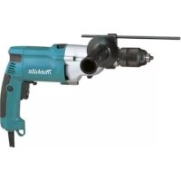
HP2051HJ - Drill MAKITA - Free user manual and instructions
Find the device manual for free HP2051HJ MAKITA in PDF.



User questions about HP2051HJ MAKITA
0 question about this device. Answer the ones you know or ask your own.
Ask a new question about this device
Download the instructions for your Drill in PDF format for free! Find your manual HP2051HJ - MAKITA and take your electronic device back in hand. On this page are published all the documents necessary for the use of your device. HP2051HJ by MAKITA.
USER MANUAL HP2051HJ MAKITA
The following show the symbols used for the tool. Be sure that you understand their meaning before use.
Symboles
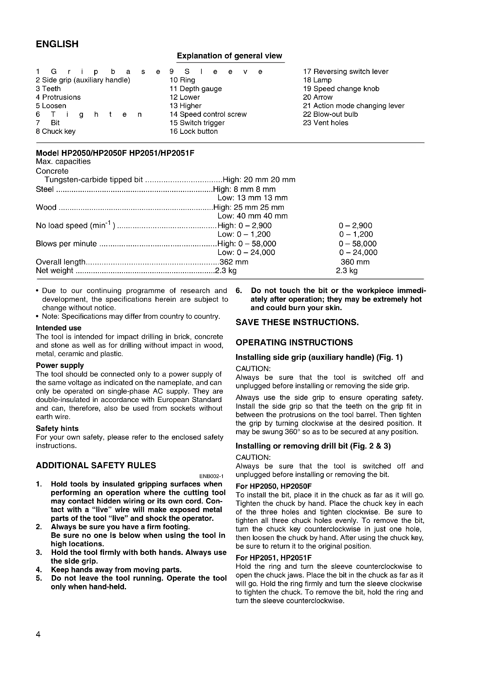
- Due to our continuing programme of research and development, the specifications herein are subject to change without notice.
- Note: Specifications may differ from country to country.
Intended use
The tool is intended for impact drilling in brick, concrete and stone as well as for drilling without impact in wood, metal, ceramic and plastic.
Power supply
The tool should be connected only to a power supply of the same voltage as indicated on the nameplate, and can only be operated on single-phase AC supply. They are double-insulated in accordance with European Standard and can, therefore, also be used from sockets without earth wire.
Safety hints
For your own safety, please refer to the enclosed safety instructions.
ENB002-1
- Hold tools by insulated gripping surfaces when performing an operation where the cutting tool may contact hidden wiring or its own cord. Contact with a "live" wire will make exposed metal parts of the tool "live" and shock the operator.
- Always be sure you have a firm footing. Be sure no one is below when using the tool in high locations.
- Hold the tool firmly with both hands. Always use the side grip.
- Keep hands away from moving parts.
-
Do not leave the tool running. Operate the tool only when hand-held.
-
Do not touch the bit or the workpiece immediately after operation; they may be extremely hot and could burn your skin.
SAVE THESE INSTRUCTIONS.
OPERATING INSTRUCTIONS
Installing side grip (auxiliary handle) (Fig. 1)
CAUTION:
Always be sure that the tool is switched off and unplugged before installing or removing the side grip.
Always use the side grip to ensure operating safety. Install the side grip so that the teeth on the grip fit in between the protrusions on the tool barrel. Then tighten the grip by turning clockwise at the desired position. It may be swung 360^ so as to be secured at any position.
Installing or removing drill bit (Fig. 2 & 3)
CAUTION:
Always be sure that the tool is switched off and unplugged before installing or removing the bit.
For HP2050, HP2050F
To install the bit, place it in the chuck as far as it will go. Tighten the chuck by hand. Place the chuck key in each of the three holes and tighten clockwise. Be sure to tighten all three chuck holes evenly. To remove the bit, turn the chuck key counterclockwise in just one hole, then loosen the chuck by hand. After using the chuck key, be sure to return it to the original position.
For HP2051, HP2051F
Hold the ring and turn the sleeve counterclockwise to open the chuck jaws. Place the bit in the chuck as far as it will go. Hold the ring firmly and turn the sleeve clockwise to tighten the chuck. To remove the bit, hold the ring and turn the sleeve counterclockwise.
Depth gauge (Fig. 4)
The depth gauge is convenient for drilling holes of uniform depth. Loosen the side grip and insert the depth gauge into the hole in the grip base. Adjust the depth gauge to the desired depth and tighten the side grip.
NOTE:
The depth gauge cannot be used at the position where the depth gauge strikes against the gear housing.
Switch action (Fig. 5)
CAUTION:
Before plugging in the tool, always check to see that the switch trigger actuates properly and returns to the "OFF" position when released.
To start the tool, simply pull the switch trigger. Tool speed is increased by increasing pressure on the switch trigger. Release the switch trigger to stop. For continuous operation, pull the switch trigger and then push in the lock button. To stop the tool from the locked position, pull the switch trigger fully, then release it.
A speed control screw is provided so that maximum tool speed can be limited (variable). Turn the speed control screw clockwise for higher speed, and counterclockwise for lower speed.
Lighting up the lamps (HP2050F, HP2051F)
CAUTION:
Do not look in the light or see the source of light directly.
To turn on the lamp, pull the trigger. Release the trigger to turn it off.
NOTE:
Use a dry cloth to wipe the dirt off the lens of lamp. Be careful not to scratch the lens of lamp, or it may lower the illumination.
Reversing switch action (Fig. 6)
This tool has a reversing switch to change the direction of rotation. Move the reversing switch lever to the position (A side) for clockwise rotation or to the position (B side) for counterclockwise rotation.
CAUTION:
- Always check the direction of rotation before operation.
- Use the reversing switch only after the tool comes to a complete stop. Changing the direction of rotation before the tool stops may damage the tool.
Speed change knob (Fig. 7)
Two speed ranges can be preselected with the speed change knob. Turn the speed change knob so that the arrow on the tool body points toward the "I" position on the knob for low speed or "II" position for high speed. If it is hard to turn the knob, first turn the chuck slightly in either direction and then turn the knob again.
CAUTION:
- Use the speed change knob only after the tool comes to a complete stop. Changing the tool speed before the tool stops may damage the tool.
- Always set the speed change knob to the correct position. If you operate the tool with the speed change knob positioned halfway between the "I" and "II" position, the tool may be damaged.
Selecting the action mode (Fig. 8)
This tool has an action mode change lever. For rotation with hammering, slide the action mode change lever to the right ( symbol). For rotation only, slide the action mode change lever to the left ( symbol).
CAUTION:
Always slide the action mode change lever all the way to your desired mode position. If you operate the tool with the lever positioned halfway between the mode symbols, the tool may be damaged.
OPERATION
Hammer drilling operation
When drilling in concrete, granite, tile, etc., move the action mode change lever to the position of symbol to use "rotation with hammering" action. Be sure to use a tungsten-carbide tipped bit. Do not apply more pressure when the hole becomes clogged with chips or particles. Instead, run the tool at an idle, then remove the bit partially from the hole. By repeating this several times, the hole will be cleaned out. After drilling the hole, use the blow-out bulb to clean the dust out of the hole. (Fig. 9)
Drilling operation
When drilling in wood, metal or plastic materials, move the action mode change lever to the position of symbol to use "rotation only" action.
Drilling in wood
When drilling in wood, the best results are obtained with wood drills equipped with a guide screw. The guide screw makes drilling easier by pulling the bit into the workpiece.
Drilling in metal
To prevent the bit from slipping when starting a hole, make an indentation with a center-punch and hammer at the point to be drilled. Place the point of the bit in the indentation and start drilling. Use a cutting lubricant when drilling metals. The exceptions are iron and brass which should be drilled dry.
CAUTION:
- Pressing excessively on the tool will not speed up the drilling. In fact, this excessive pressure will only serve to damage the tip of your bit, decrease the tool performance and shorten the service life of the tool.
- There is a tremendous force exerted on the tool/bit at the time of hole break through. Hold the tool firmly and exert care when the bit begins to break through the workpiece.
- A stuck bit can be removed simply by setting the reversing switch to reverse rotation in order to back out. However, the tool may back out abruptly if you do not hold it firmly.
- Always secure small workpieces in a vise or similar hold-down device.
MAINTENANCE
CAUTION:
Always be sure that the tool is switched off and unplugged before carrying out any work on the tool.
Cleaning vent holes (Fig. 10)
Periodically clean the vent holes to prevent them from being clogged with dust, dirt or the like.
To maintain product safety and reliability, repairs, maintenance or adjustment should be carried out by a Makita Authorized Service Center.
FRANÇAIS
Descriptif
Per HP2051 e HP2051F
Para HP2051 e HP2051F
Acender as Iampadas (HP2050F e HP2051F)
PRECAUÇA:
These accessories or attachments are recommended for use with your Makita tool specified in this manual. The use of any other accessories or attachments might present a risk of injury to persons. The accessories or attachments should be used only in the proper and intended manner.
F ACCESSORIES
ATTENTION:
EC-DECLARATION OF CONFORMITY
We declare under our sole responsibility that this product is in compliance with the following standards or standardized documents,
HD400, EN50144, EN55014, EN61000
in accordance with Council Directives, 73/23/EEC, 89/336/EEC and 98/37/EC.
FRANÇAISE
DECLARATION DE CONFORMITE CE
HD400, EN50144, EN55014, EN61000.
ITALIANO
de accordo com as directivas 73/23/CEE, 89/336/CEE e 98/37/CE do Conselho.
DANSK
EU-DEKLARATION OM KONFORMITET
Michigan Drive, Tongwell, Milton Keynes,
Bucks MK15 8JD, ENGLAND
ENGLISH
Noise and Vibration
The typical A-weighted noise levels are
sound pressure level: 97 dB (A)
sound power level: 110 dB (A)
Wear ear protection.
The typical weighted root mean square acceleration value is 6m / s^2
