Sherpa Aquadue Tower S2 - Heat pump OLIMPIA SPLENDID - Free user manual and instructions
Find the device manual for free Sherpa Aquadue Tower S2 OLIMPIA SPLENDID in PDF.

| Product type | Air-to-water heat pump |
| Brand | Olimpia Splendid |
| Model | Sherpa Aquadue Tower S2 |
| Dimensions (W × D × H) | 600 × 600 × 1980 mm |
| Net weight | 171 kg |
| Operating weight | 321 kg |
| Power supply | 220-240 V ~ 1 ph, 50 Hz |
| Maximum power consumption (indoor unit) | 4.05 kW |
| Maximum current (indoor unit) | 18 A |
| Refrigerant | R32 |
| Global warming potential (GWP) | 675 |
| Maximum DHW temperature | 75 °C |
| Operating modes | Heating, cooling, domestic hot water |
| Anti-legionella function | Yes |
| Remote control | Yes (free contacts or serial) |
| Photovoltaic integration | Yes |
| Frost protection | Yes |
| Operating pressure (heating/cooling circuit) | 300 kPa max |
| Operating pressure (DHW circuit) | 600 kPa max |
| Nominal water flow rate (heating/cooling) | 0.29 to 0.38 L/s depending on version |
| Circulation pump | High efficiency, PWM control |
| Cleaning | Damp cloth and soap; do not use solvents |
| Periodic maintenance | Magnesium anode check every 2 years |
| Repairability | Original Olimpia Splendid spare parts |
Frequently Asked Questions - Sherpa Aquadue Tower S2 OLIMPIA SPLENDID
User questions about Sherpa Aquadue Tower S2 OLIMPIA SPLENDID
0 question about this device. Answer the ones you know or ask your own.
Ask a new question about this device
Download the instructions for your Heat pump in PDF format for free! Find your manual Sherpa Aquadue Tower S2 - OLIMPIA SPLENDID and take your electronic device back in hand. On this page are published all the documents necessary for the use of your device. Sherpa Aquadue Tower S2 by OLIMPIA SPLENDID.
USER MANUAL Sherpa Aquadue Tower S2 OLIMPIA SPLENDID
INSTRUCTIONS FOR INSTALLATION, USE AND MAINTENANCE EN
INSTRUCTIONS POUR L'INSTALLATION, L'EMPLOI ET L'ENTRETIEN FR
HANDBUCH FÜR INSTALLATION, GEBRAUCH UND WARTUNG DE
INSTRUCCIONES PARA LA INSTALLACION, USO Y MANTENIMIENTO ES
Caution: risk of fire
1.1 - UNITÀ ESTERNA (Fig.1)
1.2 - UNITÀ INTERNA (Fig.2-4)
2.2.1 - Removal of the front panel 17
2.2.2 - Access to internal components 18
2.3- INSTALLATION OF THE EXTERNAL UNIT 18
2.4 - OPERATIONAL LIMITS 19
3-CONNECTIONS 19
3.1- REFRIGERANT CONNECTIONS 19
3.1.1 - Tests and checks 20
3.1.2 - Loading of additional refrigerant 21
3.2 - HYDRAULIC CONNECTIONS 21
3.2.1 - Circulation pumps 23
3.2.2 - Hydraulic circuit 24
3.3 - SYSTEM WATER REFERENCE VALUES 25
3.4 - HYDRAULIC SYSTEM FILLING 25
3.5 - CIRCULATION PUMP ALARM 25
3.6 - ELECTRICAL CONNECTIONS 26
3.6.1 - Access to electrical connections 27
3.6.2 - Connection cables 28
3.6.3 - Electrical connections 28
4-INSTALLATION CHECKS 29
4.1- PREPARATION FOR FIRST COMMISSIONING 29
4.2 - CHECKS DURING AND AFTER FIRST COMMISSIONING 30
5-CONTROL PANEL 31
5.1- MAIN SCREEN 31
5.2 - HOLIDAY MODE 32
5.3 - NIGHT MODE 32
5.4- MODES OF OPERATION 32
5.5- TEMPERATURES SETTING 33
5.6- SYSTEM TEMPERATURES 33
5.7- TIMER MENU 33
EN-1
5.8 - FUNCTIONS MENU 34
5.8.1 - Synoptic 35
5.8.2 - Climatic curves 35
5.8.3 - Alarm 36
5.8.4 - Counters 39
5.8.5 - Date / clock 39
5.8.6 - Service 40
5.8.7 - System 40
5.8.8 - Display 41
5.8.9 - Special functions 41
5.9- SOFTWARE UPDATE 44
6 - MANAGEMENT AND CONTROLS 45
6.1 - INTERNAL UNIT ADDITIONAL ELECTRIC HEATERS MANAGEMENT 45
6.1.1 - Backup 45
6.1.2 - Low-temperature start 45
6.1.3 - Legionella prevention function 45
6.2- REMOTE CONTROL 46
6.2.1 - Serial 46
6.2.2 - Free contacts 46
6.3- PHOTOVOLTAIC SYSTEM 47
6.4 - SOLAR THERMAL SYSTEM 47
6.5 - CHECK OF THE CIRCULATION PUMPS 48
7 - USE 48
7.1 - PRODUCTION OF DOMESTIC HOT WATER 48
7.2 - ANTIFREEZE PROTECTIONS 49
7.3 - DEACTIVATION AND SWITCHING OFF FOR LONG PERIODS 49
8 - MAINTENANCE AND CLEANING 49
8.1 - CLEANING 49
8.2- PERIODIC MAINTENANCE 49
8.2.1 - Check of the domestic hot water reservoir magnesium anode 50
symbol on the product or its packaging indicates that the appliance cannot be treated as normal domestic trash, but must be handed in at a collection point for recycling electric and electronic appliances.
Your contribution to the correct disposal of this product protects the environment and the health of your fellow men. Health and the environment are endangered by incorrect disposal.
Further information about the recycling of this product can be obtained from your local town hall, your refuse collection service, or in the store at which you bought the product.
This regulation is valid only in EU member states.
EN-2
ILLUSTRATIONS
The illustrations are grouped on the initial pages of the manual
MAIN INDEX
The main index of this manual is given on page "EN-1"

0 - WARNINGS
0.1 - GENERAL INFORMATION
First of all, we would like to thank you for choosing our appliance.
This document is confidential pursuant to the law and may not be reproduced or transferred to third parties without the explicit authorisation of the manufacturer.
The appliance may undergo updates and therefore have details different from those represented, without prejudice to the texts contained in this manual.
0.2 - SYMBOLS
The pictograms in the next chapter provide the necessary information for correct, safe use of the machine in a rapid, unmistakable way.
0.2.1 - Editorial pictograms

Service
Refers to situations in which you should inform the SERVICE department in the company:
CUSTOMER TECHNICAL SERVICE.
Index
Paragraphs marked with this symbol contain very important information and recommendations, particularly as regards safety.
Failure to comply with them may result in:
- danger of injury to the operators
- loss of the warranty
- refusal of liability by the manufacturer.

Raised hand.
Refers to actions that absolutely must not be performed.
als to the personnel that the operation described could cause electrocution if not performed according to the safety rules.

GENERIC DANGER
It informs the personnel concerned that if the operation is not carried out in compliance with the safety regulations, it presents the risk of suffering physical damage.

DANGER DUE TO HEAT
It informs the personnel concerned that if the operation is not carried out in compliance with the safety regulations, it presents the risk of burns due to contact with components at very high temperatures.

DANGER
cates that the appliance uses flammable refrigerant. If the refrigerant leaks and is exposed to an external ignition source, the risk of fire exist.

WARNING
dicates that this document must be read carefully before installing and/or using the appliance.
- Indicates that this document must be read carefully before any maintenance and/or cleaning operation.

ENTION
cates that the assistance personnel must handle the appliance respecting the installation manual.
0.3 - GENERAL WARNINGS
WHEN USING ELECTRICAL EQUIPMENT, BASIC SAFETY PRECAUTIONS MUST ALWAYS BE FOLLOWED IN ORDER TO REDUCE RISKS OF FIRE, ELECTRIC SHOCKS AND INJURY, INCLUDING THE FOLLOWING:
- This document is restricted in use to the terms of the law and may not be copied or transferred to third parties without the express authorization of the manufacturer, OLIMPIA SPLENDID.
Our machines are subject to change and some parts may appear different from the ones shown here, without this affecting the text of the manual in any way. - Read this manual carefully before performing any operation (installation, maintenance, use) and follow the instructions contained in each chapter.
- Make all personnel involved in transport and installation of the machine aware of these instructions.
- The manufacturer is not responsible for damages to persons or property caused by failure to follow the instructions in this manual.
- The manufacturer reserves the right to make any changes it deems advisable to its models, although the essential features described in this manual remain the same.
- The installation and maintenance of air-conditioners like this one may be hazardous as they contain a cooling gas under pressure as well as powered parts.
- The installation, first startup and subsequent maintenance should be carried out exclusively by authorized, qualified personnel.
- Failing to comply with the instructions contained in this manual, and using the unit with temperatures exceeding the permissible temperature range will invalidate the warranty.
- During installation and maintenance, respect the precautions indicated in the manual, and on the labels applied inside the units, as well as all the precautions suggested by good sense and by the safety regulations in effect in your country.
- Always wear gloves and protective goggles when performing any operations on the refrigerating side of the units.

- The air-water heat pumps must not be installed in environments with the presence of flammable gasses, explosive gasses, in very moist environments (laundries, greenhouses, etc.), or in rooms where there is other machinery generating a strong heat source.
EN-5

- In case of replacement of parts, use only original OLIMPIA SPLENDID parts.

- IMPORTANT!
prevent any electrocution risk, it is essential to disconnect all the power circuits before performing electrical connections and any cleaning and/or maintenance operation on the appliances.

- The installation of OLIMPIA SPLENDID appliances must be carried out by an authorized company which, at the end of the work, releases to the plant manager a declaration of conformity in accordance with the Standards in force and with the indications supplied by OLIMPIA SPLENDID in this manual.

- Install the air-water heat pump respecting the instructions in this manual; if the installation is not carried out correctly, the risk of water leakage, electrical shock or fire may be present.
It is recommended to exclusively use the supplied components specifically designed for installation; the use of components different from these may result in water leakage, electrical shock or fire.

- Once installation is complete, check that there's no leakage of refrigerant (the refrigerating liquid, if exposed to a flame, produces toxic gas).

- Upon installation or repositioning of the system, make sure that no substances enter the refrigerating circuit, such as air, different from the specified refrigerating liquid (the presence of air or other foreign substances in the refrigerating circuit may cause a huge increase in pressure or breakage of the system, with consequent damages to people).

- In case water leakages, switch off the unit and stop the supplies of the internal and external units by means of the main switches.
Call, as soon as possible, the Technical Assistance Service of OLIMPIA SPLENDID or professionally qualified personnel and do not intervene personally on the appliance.

-
If in the system there is a boiler, check, during operation of the latter, that temperature of the water circulating inside the heat air-water pump does not exceed 65^ .
-
This instruction manual is an integral part of the appliance and, accordingly, it must be kept with care and will ALWAYS accompany the appliance even in the case of its sale to another owner or user or in case of transfer to another system. In case of damaging or loss, ask for a new one to your local Technical Assistance Service of OLIMPIA SPLENDID.

- Make sure the ground connection is carried out; do not ground the appliance on distribution pipes, overvoltage arresters or on the ground of
EN-6

OLIMPIA SPLENDID
the telephone system; if not performed correctly, the ground connection may result in electrical shock; momentary high-intensity power surges caused by lightings or other causes may damage the air-water heat pump. It is recommended to install a ground leakage breaker; the failure to install this device may result in electrical shock.

- It is prohibited to touch the appliance if you are barefoot or with wet or moist parts of your body.

- It is prohibited to change the safety or adjustment devices without authorization or indications of the appliance manufacturer.

- It is prohibited to pull, disconnect, twist the electrical cables coming out from the appliance, even if the latter is disconnected from the power supply network.

- It is prohibited to insert objects or substances through the air intake and delivery grids.

- It is prohibited to open the access doors to the internal parts of the appliance without first positioning the main switch of the system to "off".

- It is prohibited to disperse and leave packaging material within the reach of children as it can be potential source of danger.

- Do not emit R32 gas into the atmosphere; R32 is a fluorinated greenhouse gas with a Global Warming Potential (GWP) = 675.

-
This unit is compliant with the European Directives: low voltage 2014/35/EU;
-
Electromagnetic compatibility 2014/30/EU;
- restriction of the use of hazardous substances in electrical and electronic equipment 2011/65/EU (RoHS); and successive amendments.
0.4 - NOTES REGARDING FLUORINATED GASES

-
This climate control appliance contains fluorinated gas. For specific information regarding the type and quantity of gas, refer to the data plate affixed to the unit.
-
The installation, assistance, maintenance and repair of the appliance, must be performed by a qualified certified technician.
-
Product removal and re-cycling operations must be performed by a qualified certified technician.
- If the system has a leak-detection device installed, the checks for leaks must be performed at least every 12 months.
- When the unit is checked for leaks, keeping a record of all inspections is highly recommended.

- Before starting to operate on the appliance, it is necessary to check the zone surrounding the equipment to make sure there are no dangers of fire and risks of combustion.
To repair the refrigerating system, it is necessary to take the following precautions before starting the intervention on the system.

This product must be used exclusively according to the specifications indicated in this manual. Use different to that specified, could cause serious injuries.
THE MANUFACTURER IS NOT LIABLE FOR INJURY/Damage TO PERSONS/OBJECTS DERIVING FROM FAILURE TO COMPLY WITH THE REGULATIONS CONTAINED IN THIS MANUAL.

- It is necessary to define the area around the work space and to avo working in tight spaces. Ensure safe work conditions by checking flammable material.

- All personnel in charge of maintenance and people which work in the surrounding area must be instructed on the type work they are going to carry out.

- The zone MUST be checked with a specific refrigerating liquids detector before and during work, so that the technician is aware of potentially flammable atmospheres. Make sure the detection device of the leaks is suitable for use with flammable refrigerants, then that it does not produce sparks and that is adequately sealed or intrinsically safe.
- The leaks electronic detectors may need calibration. If necessary, calibrate them in a zone free of refrigerant.
- Make sure the detector is not a potential source of combustion and that it is suitable for the refrigerant used. The device for detection must be set at a percentage of the refrigerant LFL and must be calibrated for the used refrigerant; the appropriate percentage of gas (maximum 25% ) must be confirmed.
5a. Fluids for the detection of losses are suitable for most part of the refrigerants. Detergents containing chlorine MUST be avoided. Danger of corrosion of copper pipes. - If the presence of a leak is suspected, all open flames must be removed. If a fluid leak which requires brazing is encountered, all refrigerant must be
EN-8
collected from the system or insulated (by means of shut off valves) in a part of the system away from the leak. Then, bleed nitrogen without oxygen (OFN) through the system both before and after the brazing process.

- In case it is necessary to carry out a hot work on the appliance, IT IS NECESSARY to have a powder or CO_2 fire extinguisher available.

- To carry out a work which includes exposition of pipes which contain or contained a flammable refrigerant, DO NOT use sources of combustion.
Risk of fire or explosion!
-
All sources of combustion (even a lit cigarette) should be kept away from the place in which all operations during which the flammable refrigerant may be released in the surrounding space must be carried out.
-
Make sure the area is adequately ventilated before intervening inside the system; a continuous degree of ventilation must be present.

-
DO NOT use means different from those recommended by the manufacturer in order to speed up the defrosting process or for cleaning.
-
Before any operation, always check that:
-
the condensers are unloaded.
The operation must be carried out safely to avoid the risk of producing sparks; - there are no live electrical components and that the cables are not exposed while loading, recovering or bleeding the system;
-
there is continuity in the ground connection.
-
All electrical power supplies must be disconnected from the appliance on which you are working.
If it is absolutely necessary that the appliance has electrical power supply, it is necessary to place a leak detector permanently operational in the most critical point.

- Make sure the seals and sealing materials have not deteriorated. A possible development of flammable atmospheres.

- Do not apply any net inductive or capacity load to the circuit without making sure that this operation won't make you exceed the voltage and current permitted for the appliance in use.
The appliance for the test must have correct nominal values.
15a The only components on which you can operate in flammable atmosphere are those intrinsically safe.
The test device must be set with the correct conditions. The components must be replaced ONLY with parts of the manufacturer. Danger of loss of refrigerant in the atmosphere, risk of explosion.

-
Periodically check that the cables are not subject to wear, corrosion, excessive pressure, vibrations, sharp edges or any other hostile environmental situation.
-
When intervening inside the refrigerating circuit to carry out repairs or for any other reason, the conventional procedures must be followed:
-
remove the refrigerant;
- bleed the circuit with an inert gas;
- evacuate;
- bleed again with an inert gas;
-
open the circuit by cutting or by means of brazing.
-
The load of refrigerant must be stored in the specific custody cylinders.
The system must "cleaned" with OFN to make the unit safe. It may be necessary to repeat this process several times.
DO NOT use compressed air or oxygen for this operation.
18a. Make sure that, while recharging the system THERE IS no contamination of the various elements. The pipes or conducts MUST be as short as possible to minimize the content of refrigerant inside them.
- The cylinders must be kept in vertical position.
Only use cylinders suitable for collection of refrigerants.
The cylinders must be complete of a pressure-relief valve and switch off valves in good conditions.
A set of calibrated weighing scales must also be available.

- The pipes must be equipped with couplings for disconnection and must NOT present leaks.
Before using the collection machine, check that it underwent correct maintenance and that the possible associated electric components are sealed, to prevent switching on in case of leak of refrigerant.
- Make sure the refrigerating system is earthed before proceeding with reloading of the system with refrigerant.
Label the system when reloading is complete.
Pay particular attention not to overload the refrigerating system.

- Before proceeding with reloading, the system must undergo the pressure test with OFN and the tightness test at the end of reloading, but before commissioning.
It is necessary to carry out an additional tightness test before leaving the site.
22a. Remove the refrigerant safely. Move the refrigerant in the cylinders suitable for recovery. Make sure there is a correct number of cylinders to contain the charge entirely. All cylinders are labelled for this type of refrigerant (special cylinders for refrigerant recovery).
The cylinders must be complete of a pressure relief valve and of and of the corresponding closure valve in good conditions. Empty cylinders are evacuated and, if possible, cooled down before recovery.
EN-10
22b. Equipment for recovery must be within the range of the technician, in good conditions, with a series of instructions and must be suitable for recovery of all the refrigerants (even flammable ones). A series of calibrates scales must be available and in good conditions. Check that the pipes are in good conditions and complete of disconnection joints without losses.
22c. Before using the machine for recovery, check that it is in good operating conditions, that it has been adequately maintained and that all the associated electric components are sealed to prevent switching-in in case of release of refrigerant. In case of doubt, please contact the manufacturer.
- Collected refrigerant must be returned to the fluid supplier in the appropriate collection cylinder, compiling the corresponding Handover Note of Scraps.
DO NOT mix the refrigerants in the collection units and, in particular, in the cylinders. - If the compressors or their oils must be removed, make sure they have been emptied at an acceptable level to be sure that the flammable refrigerant does not remain in the lubricant.
This process must be carried out before the compressor returns to the suppliers.
Only use electric heating on the compressor body to speed up this process.
- Make sure that contamination between different refrigerants does not occur when a reloading equipment is used.
The flexible pipes or ducts must be as short as possible to reduce the quantity of refrigerant inside them to a minimum. - The appliance must be installed, operated and placed in a room with a surface higher than the one indicated in table 1.
- Do not drill nor burn the unit.
-
The replaced electric components MUST be suitable and correspond to the appliance specifications. Every maintenance operation MUST be carried out as described in this manual. Contact the manufacturer in case of doubt.
-
Apply the following checks:
-
The size of the room inside which are located the parts containing the refrigerant, are in accordance with the current quantity of charge of the refrigerant (see par. 0.5);
- The ventilation device works correctly and the outlets are not clogged;
- The markings on the machine must always be visible and readable, correct them if not;
-
The pipelines ore the components containing refrigerant MUST be installed in a place where no substance may corrode them, unless the components are built with materials intrinsically resistant against corrosion or are suitably protected against this risk.
-
All the refrigerant must be recovered safely, also collect a sample of oil and refrigerant if it is necessary to collect a sample of oil and refrigerant in case an analysis is necessary before the reuse of the recovered refrigerant. Before carrying out the procedure, electrically insulate the system and make sure that:
-
the mechanical movement equipment of the cylinders containing refrigerant are available;
- all the personal protective equipment is used correctly;
- the recovery process is supervised, at any moment, by a competent person;
- the equipment and recovery cylinders are compliant with the standards.
Empty the system and, if that is not possible, use a collector in order to be able to remove the refrigerant.
Before the recovery starts, make sure the cylinder is positioned on the scale and start the recovery machine working according to the instructions.
- DO NOT fill the cylinders excessively (the liquid must not be higher than 80% of the volume).
DO NOT exceed, even temporarily, the maximum operating pressure of the cylinder.
Once the process is complete, as previously described, make sure the equipment and the cylinders are removed. Before switching on the appliance, check that all the insulation valves are closed.
- Recovered refrigerant must not be discharged in another refrigerating systems unless it has been cleaned and checked.
0.5 - SPECIAL REQUIREMENTS FOR R32 GAS

The tables refer to 8-10kW units. For 4-6kW units a maximum length of the pipes of 29m is allowed and no evaluation of the minimum area is necessary.
- The pipes must be protected against physical damages.
The installation of the pipes must be the minimum one.
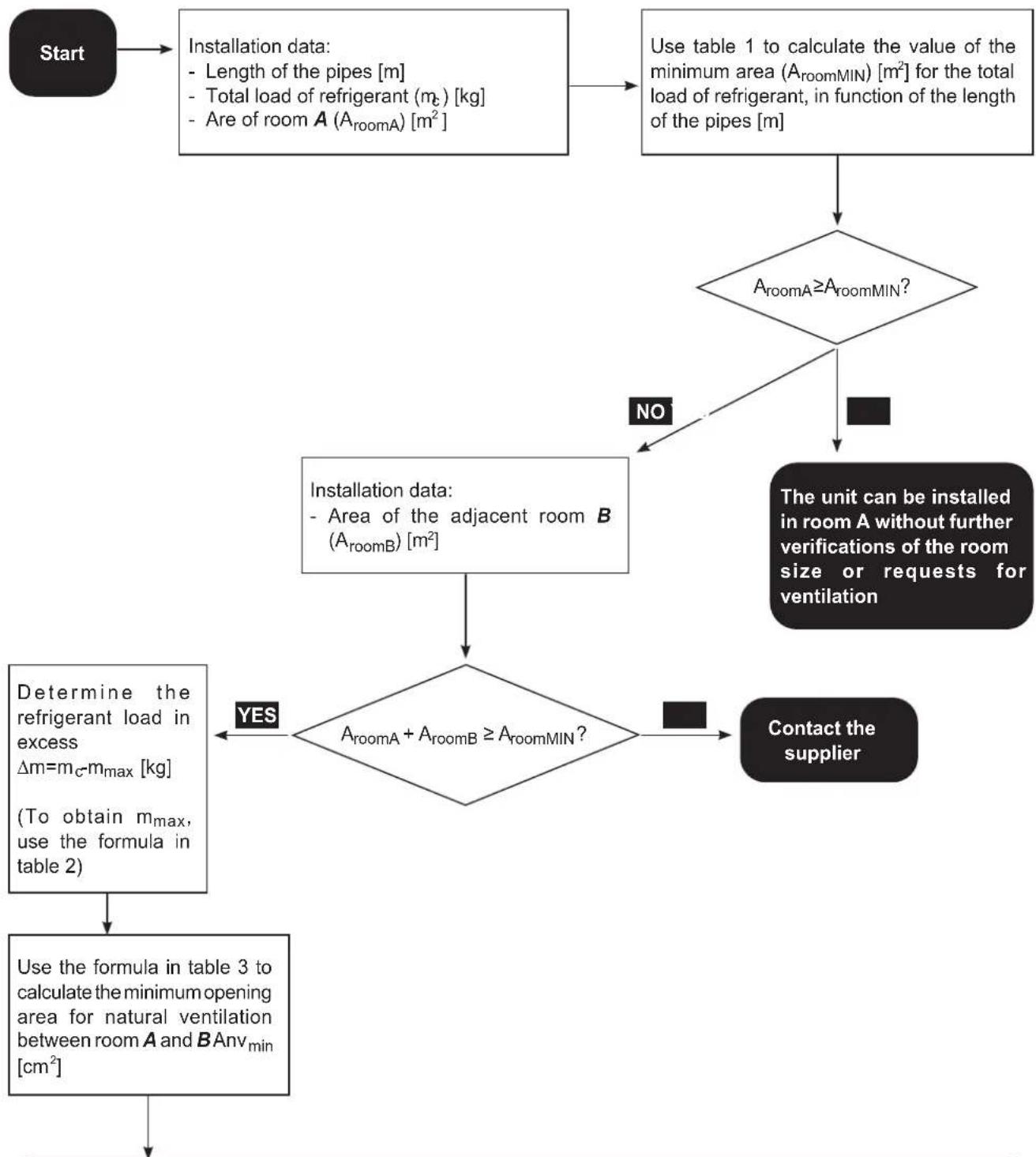
- If the total load of refrigerant in the system is < 1,842kg (namely if the pipes length is ≤ 20m for 8/10kW units), there are no requirements of minimum area to be evaluated.
If the refrigerant load exceeds 1,842kg (namely if the length of the pipes is ≥ 20m for 8/10kW units), the request for minimum area must be checked as shown by the following flow chart.
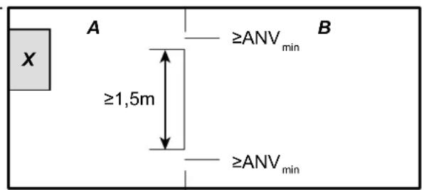
X- Internal unit
A- Room where the internal unit is installed (on which the evaluation of the minimum area must be done)
B- Room adjacent to A
EN-12
Unit "X" can be installed in room "A" if:
- Two ventilation openings (permanently open) are provided for between room A and B , an upper one and a lower one.
- Lower opening: The lower opening must check Anv min. It must be as close as possible to the floor. If ventilation starts from the floor, height must be at least 20mm. The lower limit of the opening must be positioned at less of 100mm from the floor. At least 50% of the required opening area must be located at less than 200mm from the floor.
The whole area of the opening must be located at less than 300mm from the floor.
- Upper opening: The upper opening area must have a length ≥ than/to the one of the lower. The lower limit of the upper opening must be positioned at least 1,5m above the upper limit of the lower opening. Ventilation openings towards the exterior are NOT considered suitable (the user may close them when it's cold).
Table 1
Maximum load of refrigerant permitted in one room: internal unit
| Length of the pipes (m) | Load of refrigerant (kg) | \( {\mathrm{A}}_{\text{roomMIN }}\left( {\mathrm{m}}^{2}\right) \) H=1800mm |
| 15 1.650 - | ||
| 16 1.688 - | ||
| 17 1.726 - | ||
| 18 1.764 - | ||
| 19 1.802 - | ||
| 20 1.840 - | ||
| 21 1.878 4,53 | ||
| 22 1.916 4,62 | ||
| 23 1.954 4,71 | ||
| 24 1.992 4,81 | ||
| 25 2.030 4,90 | ||
| 26 2.068 4,99 | ||
| 27 2.106 5,08 | ||
| 28 2.144 5,17 | ||
| 29 2.182 5,26 | ||
| 30 2.220 5,36 |
Table 2
The maximum load of refrigerant in a room must be compliant with what follows:
$$ \mathsf {m} _ {\max } = 2, 5 \times (\mathsf {L F L}) ^ {(5 / 4)} \times \mathsf {h} _ {0} \times (\mathsf {A}) ^ {1 / 2} $$
And must not be lower than
$$ m _ {\max } = S F \times L F L \times h _ {0} \times A $$
| Acronym Description | |
| mmax | Is the maximum allowed load of refrigerant in the system in kg |
| LFL Is the lower flammability in kg/m3 | |
| A Is the room area in m2 | |
| h0 | Is the release height, the vertical distance in (m) from the floor to the release point when the appliance is installed |
| SF Is a safety factor with a value of 0,75 | |

- Systems with a load of refrigerant < 1,842 kg are not subject to minimum area requests.
Loads exceeding 2,22kg are not accepted (maximum length of the pipes equal to 30m
Only for 8/10kW units.
Table 3
Minimum ventilation area
for natural ventilation: internal unit
$$ \mathrm {A n v} _ {\min } = \frac {\mathrm {m} _ {\mathrm {c}} - \mathrm {m} _ {\max }}{\mathrm {L F L} \times 1 0 4} \mathrm {x} \sqrt {\mathrm {m} \frac {\mathrm {A}}{\mathrm {m a x}} \mathrm {x} \frac {\mathrm {M}}{\mathrm {M} - 2 9}} $$
Acronym Description
| \( {\mathrm{{Anv}}}_{\text{min }} \) | Is the minimum opening for natural ventilation in \( {\mathrm{m}}^{2} \) |
| \( {\mathrm{m}}_{\mathrm{C}} \) | Is the effective load of refrigerant in the system in kg |
| M Is the molar mass of the refrigerant | |
| g Is gravity | acceleration of 9,81 m/s |
| 29 Is the average molar mass of air in kg | |
| \( {A}_{\min } \) | Is the required minimum area of the room in \( {\mathrm{m}}^{2} \) |
Minimum ventilation area in function of the area of the room for various lengths of pipes and then different loads of the unit:
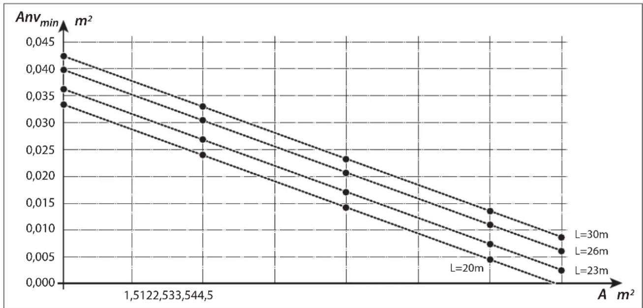

The formulas and tables are compliant with IEC 60335-2-40: 2018 GG2. LFL = 0,307 , m = 52 g/mol for R32.
1 - DESCRIPTION OF THE APPLIANCE
1.1 - EXTERNAL UNIT (Fig.1)
For the characteristics of the external unit, please refer to the installation manual of the external unit.
1.2 - INTERNAL UNIT (Fig.2-4)
The dimensions of the internal unit are:
| UI SHERPA AQUADUE TOWER S2 E SMALL | |
| Width (mm) | 600 |
| Depth (mm) | 600 |
| Height (mm) | 1980 |
| Weight (kg) | 171 |
| Weight in use (kg) | 321 |
EN-15
List of main components of the internal unit (Fig.4)
- Three-way valve
- Conditioning circuit circulation pump
- Safety valve (6 bar DHW circuit)
- Reheating electric heaters collector
- 3 bar conditioning circuit safety valve
- Electric heaters safety thermostats
- Automatic air vent valves
8 Conditioning circuit heat exchanger - Flow switches
- Conditioning circuit manometer
- DHW circuit filling unit
- DHW circuit circulation pump
- DHW circuit heat exchangers
- DHW circuit expansion vessel
- Domestic Hot Water (DHW) reservoir
- Tester anode
-
Conditioning circuit expansion vessel
-
Touch screen display
- Electric panel assembly
- Cable tie
- DHW circuit evaporator water flow adjuster
- DHW thermostatic mixer
A. Adjustable support feet
B. DHW reservoir emptying tap
C. Magnesium anode access cap
D. Tester anode verification button
E. Cable terminal fixing nut + tester anode
F. Magnesium anode
1.3 - LIST OF SUPPLIED COMPONENTS
The appliances are shipped with standard packaging composed of an enclosure and cardboard corners and a series of expanded polystyrene guards.
Under the packaging of the units is located a 750 × 750 mm pallet which eases transport and displacement operations.
Inside the packaging, together with the internal unit, the following components are supplied:
- External air sensor kit
Y-shaped filter
1.4 - RECEIPT AND UNPACKING
The packaging is made up from suitable material and performed by expert personnel.
The units are delivered complete and in perfect condition. However, for he quality control of the transport services, follow the warnings below:
a. On receipt of the packages, check whether the packaging is damaged. If this is the case, withdraw the goods with reserve, producing photographic proof and any apparent damage.
b. Unpack, checking the presence of the individual components with the packing lists.
c. Control that all components have not undergone damage during transport. If this is the case, inform the carrier by registered letter with acknowledgement of receipt within 3 days of receiving the goods, presenting photographic documentation.
d. Pay attention when unpacking and installing the equipment.
Sharp parts can cause injury. Pay particular attention to the edges of the structure and the fins of the condenser and evaporator.

No information concerning damage undergone can be taken into consideration after 3 days from delivery.
For any controversy the court of jurisdiction will be BRESCIA.

Keep the packaging for at least the duration of the warranty period, for any shipments to the after-sales centre for repairs. Dispos of packaging in compliance with the regulations in force regarding waste disposal.
EN-16
2 - INSTALLATION
2.1 - INSTRUCTIONS FOR INSTALLATION
To obtain the best results and optimum performance, follow the instructions for correct installation provided in this manual.

A failure to implement the indicated standards, which may cause a malfunction of the appliances, relieves OLIMPIA SPLENDID from any form of warranty and from any liability for possible damages caused to people, animals or things.

The electrical system must be compliant with legal standards, must respect the data in the technical data sheet and be must be equipped with an efficient ground system.

The appliance shall be installed in such a position that maintenance can be carried out easily.
2.2 - INSTALLATION OF THE INTERNAL UNIT
Prepare:
- A free space, sufficient to allow the removal of the guards, the connection of the water and refrigerant pipes and ordinary or extraordinary maintenance.
A water drain nearby - A compliant electrical power supply, near the internal unit
Water feeding for filling of the hydraulic circuit - Communication cable between internal and external unit (see par. 3.6.2)

The internal unit must be installed supported by the floor in an indoor environment and levelled using the adjustable feet (pos. A - Fig.4).

For the installation spaces and the position of the pipes, please refer to paragraph "Hydraulic connections" and to "Fig.5".
2.2.1 - Removal of the front panel (Fig.3)
- Open the upper door (S) rotating it upwards.
- Undo the fixing screw (X) of the front panel (P).
- Tilt the top part of the front panel (P) towards yourself and raise it upwards to release it from the pins on the unit base.
2.2.2 - Access to internal components
After removing the front panel, remove the two screws (V) which fix the cover of the electric panel (Q). (Fig.6)
- Remove the four screws (V1) and rotate the panel rightwards to have access to the components behind the electric panel (Q). (Fig.6a)
EN-17
- It is possible to release the electric panel and to hook it with the specific grooves; this way it is possible to access all the components inside the appliance and to easily proceed with installation or maintenance of the appliance.
Inside the electric board are located the components described in paragraph "3.6.3 Electrical connections". (fig.6b)
- Open the upper door (S) rotating it upwards to access the components for filling of the system with technical water. (fig. 7)
- Under the upper door (S) are located the tap (25) for filling of the system with technical water and the technical water circuit pressure manometer (26). (Fig.7)
2.3 - INSTALLATION OF THE EXTERNAL UNIT
- Install the external unit on a solid base able to bear its weight.

The external unit, if installed in an incomplete manner or on an unsuitable base, may result in damages to people or property in case of detachment from its base.

It is very important that the environment in which installation is carried out is chosen with maximum care to ensure appropriate protection of the appliance from possible impacts and consequent damages.
Choose an appropriately ventilated environment, in which external temperature does not exceed 46^ during the summer.
- Leave sufficient free space to avoid recirculation and to ease maintenance operations around the appliance.
- Prepare, under the appliance, a layer of gravel for defrosting water drainage.
- Leave some space under the unit to prevent freezing of defrosting water.

See the manual of the external unit for more detailed information on installation.

use of installation in localities subject to heavy snowfalls, mount the support of the appliance at a height higher than the maximum level of snow.
- Install the unit so that it is not affected by wind.
- Install anti-vibration blocks and a compliant power supply near the external unit.
2.4 - OPERATIONAL LIMITS
The charts define water temperature (LWT) and external air (ODT) limits within which the heat pump can work in the two cooling modes, heating and domestic water production (DHW).
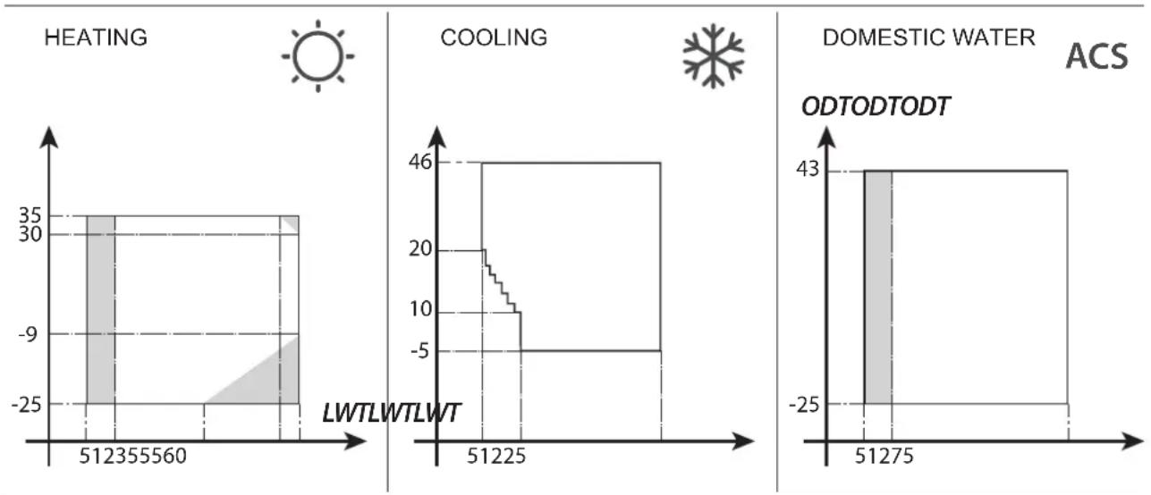

The parts highlighted in grey show the moment in which the electric heaters intervene in addition to the main circuit.
3 - CONNECTIONS
3.1 - REFRIGERANT CONNECTIONS
To define the refrigerant connection lines between the internal and external units, refer to the table below.
| Sherpa Aquadue Tower S2 E Small | ||
| 4-6 kW | 8-10 kW | |
| Maximum length of the connection pipes (m) | 29 | 30 |
| Elevation difference limit between the two units if the external unit is positioned higher (m) | 20 | 20 |
| Elevation difference limit between the two units if the external unit is positioned lower (m) | 15 | 15 |
| Additional load of refrigerant per metre beyond 15 metres of pipes (g/m) | 20 | 38 |

Exclusively use pipes with diameters which respect the required dimensions.
The maximum length of the connection lines to the internal unit MUST be compliant with the table in paragraph "3.1" topping up the load of R32 as envisaged (see par.3.1.2). Do not install the units beyond the maximum allowed difference in level between internal and external unit.
Complete the refrigerant circuit by connecting the internal unit with the external unit by means of the insulated copper pipes.
EN-19

- Exclusively use insulated copper pipes specific for refrigeration which are supplied clean and sealed at their ends.
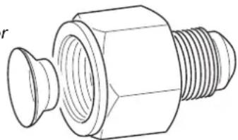
For models SHERPA S2 E (4-6 kW), use the supplied reducer for the 1/4" liquid pipe.
The refrigerant connections of the internal unit are behind the electric panel, the ones of the external units are on the right side and, in order to access them, it is necessary to remove the guard. (fig.9-10)
U1. Internal unit 5/8 gas line.
U2. Internal unit 3/8 liquid line.
U3. External unit 5/8 gas line valve.
U4. 1 / 4^ liquid line valve for U.E. SHERPA S2 E (4-6 kW); 3 / 8^ for U.E. SHERPA S2 E (8-10 kW).
- Identify the path of the pipes in order to reduce length and bends of the pipes as much as possible and to obtain maximum performance of the system.
- Insert the refrigerant lines in a cable gland duct (possibly with internal separator) of the appropriate dimensions fixed to the wall through which the pipes and the electric cables will pass.
- Cut the pipe sections abounding of approximately 3 - 4cm on length.

Cut exclusively using a wheel pipe cutter while tightening at small intervals in order not to crush the pipe.
- Remove possible burrs using the specific tool.
- Insert the fixing nut in the pipe before flaring (fig.11).
- Flare the ends of the pipes using the specific tool flawlessly without breakages, cracks or cleavage (fig.11).
- Manually screw the nut of the pipe on the coupling thread.

- Screw completely using a fork wrench to keep the threaded part of the coupling stationary.
On the nut, use a torque wrench calibrated with the following values based on the dimensions of the pipes to avoid deformations:
Diameter 3/8" 34 N.m < tightening torque < 42 N.m
- Diameter 5/8" 68 N.m < tightening torque < 82 N.m
3.1.1 - Tests and checks
Once the connections are complete, check for perfect sealing of the refrigerant system.

To carry out the operations described below it is necessary to use a manometer unit specific for R32 and a vacuum pump with minimum flow rate of 40l / min
a. Unscrew the caps of the service valves stems, both of the gas and of the liquid (fig. 13).
b. Connect the vacuum pump and manometer unit by means of the flexible pipes with 5 / 16 coupling to the service connection of the gas line (fig.14).
c. Switch on the pump and open the taps of the manometer unit.
d. Lower pressure up to -101kPa (-755mmHg, -1bar).
e. Maintain underpressure for at least 1 hour.
f. Close the taps of the manometer unit and switch off the pump.
g. After 5 minutes, only if pressure remained at -101kPa (-755mmHg, -1bar), pass to the operation at step "h".
If pressure inside the circuit raised to a value higher than -101kPa (-755mmHg, - 1bar), it is necessary to proceed with the search for the leak (by means of soap solution with refrigerant circuit under nitrogen pressure 30 bar).
Once the leak has been detected and repaired, it is necessary to restart from step "c".
h. Use a 4mm hexagonal wrench to completely open the stem of the liquid valve.
i. Use a 5mm hexagonal wrench to completely open the stem of the gas valve.
I. Remove the load flexible pipe connected to the service connection of the gas pipe.
m. Reposition the cap of the service connection of the gas pipe and fix it with a fork or normal wrench.
n. Reposition the caps of the service valves stems, both of the gas and liquid, then secure them.
Figure 13:
- Valve stem
- Valve stem cover
- Loading hole
- Main valve
Figure 14:
- Manometer unit
- Possible vacuum gauge
- Vacuum pump
-
Tap of the flexible pipe (open)
-
Service connection (closed)
- Gas pipe
- Liquid pipe
- External unit
3.1.2 - Loading of additional refrigerant
- If the length of the pipes is higher than 15m , top up the refrigerant as indicated in the table in paragraph "REFRIGERANT CONNECTIONS".
- Indicate the data of the external unit load (1), of the additional refrigerant quantity (2) and the total load of the system (1 + 2) on the supplied label (fig.15).
Figure 16:
R1. Manometer unit
R2. Possible vacuum gauge
R3. Tap of the tank liquid
R4. Gas tank R32
R5. Service connection (closed)
R6. Gas pipe
R7. Liquid pipe
R8. External unit
3.2 - HYDRAULIC CONNECTIONS

- The choice and installation of the components is delegated, due to competence, to the installer which will have to work according to good practice regulations and the Law in force.
Before connecting the pipes, make sure that they do not contain rocks, sand, rust, dregs or, in any case, foreign bodies which may damage the system.
It is appropriate to carry out a by-pass in the system in order to be able to perform washing of the plate exchanger without disconnecting the appliance. The connection pipes must be supported so that they do not weigh on the appliance with their weight.
The hydraulic couplings are positioned in the upper part of the unit.
Figure 17-17a:
C1. Conditioning circuit water delivery pipe (1")
C2. Drinkable water inlet (3 / 4^ )
C3. Domestic hot water outlet (3 / 4^ )
C4. Conditioning circuit water return pipe (1")
C5.-C6. Refrigerant pipes connections (3/8"G - 5/8"G)
EN-21
The hydraulic connections must be complete by installing (fig.5):
- air breather valves aria in the highest points of the pipes;
- please refer to "fig.5" for the position of the hydraulic and refrigerant connections. Heights are indicative, it is recommended to use flexible elastic junctions between the system pipes and the hydraulic connections of the unit;
- stop valves (on the drinkable water inlet, on the DHW outlet, on the system water return pipe, necessary to ease maintenance operations)
- sieve water filter with 0.4 ~mm meshes on the drinkable water inlet and on the return pipe from the system to intercept possible particles in the hydraulic system. Install in an easily accessible position during cleaning operations
- thermally insulate all the components and the hydraulic pipes
- In case of installation with hydraulic connections upwards ("A"), leftwards ("C") or rightwards ("B"), it is necessary to remove from the cover the precut metal sheet part on the pipes output side. Use a hacksaw to remove the precut metal sheet.
- In case of installation with hydraulic connections leftwards ("C"), rightwards ("B") or towards the rear part of the machine, use 90^ sharp bends (two 1" and two 3/4")
- Install a non-return valve on the drinkable water inlet (see paragraph "Hydraulic circuit" - rif.18)

The minimum nominal diameter of the hydraulic connection pipes must be 1".
To allow for maintenance or repair operations, it is essential that each hydraulic connection is equipped with the corresponding manual shut-off valves.
Table 4
Necessary characteristics of the hydraulic system.
| External unit | SHERPA S2 E 4 | SHERPA S2 E 6 | SHERPA S2 E 8 | SHERPA S2 E 10 | ||
| Internal unit | SHERPA AQUADUE TOWER S2 E SMALL | |||||
| Water minimum flow rate | I/s 0,14 | 0,14 0,14 | 0,14 | |||
| Nominal water flow rate* | I/s 0,29 | 0,29 0,38 | 0,38 | |||
| System water content | Min | I | 23 | 23 | 38 | 38 |
| Max** | I | 400 | 400 | 400 | 400 | |
| Operating pressure | Max | kPa | 300 | 300 | 300 | 300 |
| System difference in level | Max | m | 20 | 20 | 20 | 20 |
| Domestic system pressure | Max | kPa | 600 | 600 | 600 | 600 |
- for floor systems
** with maximum temperature of system water of 35^
The charts in fig.18-18a-18b show the prevalence of the circulator for each speed of the hydraulic circulator and the load losses inside the machine from which the residual prevalence at the connections of the machine must be obtained, expendable on the system.

The circulation of the minimum content of the conditioning system be ensured even if the valves in the system are closed.
EN-22

OLIMPIA SPLENDID
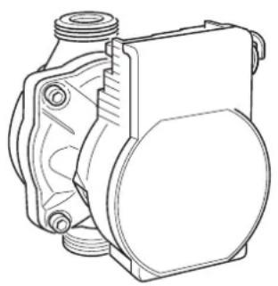
3.2.1 - Circulation pumps (fig.18-18a-18b)

The pumps are controlled through PWM, so as to set the fixed number of revolutions for pump operation.
Sherpa Aquadue Tower is equipped with one high-efficiency circulation pump.
The pumps with permanent magnet wet rotor have an electronic adjustment module with integrated frequency converter.
On the adjustment module is present a control knob.
The DHW pump is equipped with a LED indicator to display the operating status of the pump.
All the functions can be set, activated or deactivated with the control knob.
The circulator of the DHW circuit is set factory set at a constant number of revolutions I,II and III. It also may work in the modes with variable pressure difference and constant pressure difference.

- Check that load losses of the system ensure the required water flow rate (see par. 4.2).
- If higher prevalences should be necessary due to high load losses of the system, it'll be necessary to add a hydraulic separator and an external reactivation pump.
- Check if the system has the minimum required content of water to ensure good operation of the system; if it is insufficient, add such accumulation so that the required content is reached.
- The water distribution pipelines will have to be insulated adequately with polyethylene foam or similar materials. The non-return valves, the bends and the various fittings shall also be insulated adequately.
- To avoid air pockets inside the circuit, insert the automatic or manual vent devices in all the points (highest pipelines, siphons etc.) where air may accumulate.

To set the speed pump, please see paragraph 5.8.9
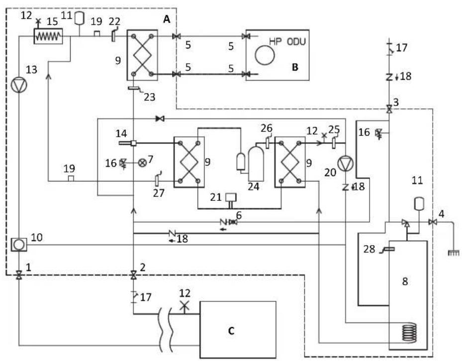
3.2.2 - Hydraulic circuit
The hydraulic scheme shows the main parts of the internal unit and a typical hydraulic circuit.
- System water outlet
- System water return
- Drinkable water inlet
- DHW outlet
- Refrigerant pipe connections
- Technical water filling tap
- Manometer
- DHW accumulation
- Plates exchanger
- 3-way diverter (integrated on board of the machine on version 3W)
- Expansion vessels
- Automatic air vent
- Technical water circulation pump
- Flow diverter
- Electric heaters collector
- Safety valves (3 bar conditioning circuit, 6 bar DHW technical water circuit)
- Net water filters
-
Non-return valves
-
Flow switches
- DHW circuit technical water circulation pump
- Thermostatic valve
- T2 system water delivery temperature probe
- T1 system water return temperature probe
- DHW circuit compressor
- High temperature DHW T6 circuit water outlet temperature probe
- T5 compressor delivery temperature probe
- DHW T7 circuit evaporator outlet temperature probe
- T3 domestic boiler temperature probe
A. Internal unit
B. External unit
C. System (fan coils, radiators or radiant panels/floors)

-
Install a sieve filter with 0,4mm meshes on the drinkable water inlet and water return from the system and from the domestic water reservoir pipes.
-
On the drinkable water inlet, on the DHW outlet, on the outlet and return of system water, install the shut-off valves necessary to ease maintenance operations.
EN-24
3.3 - SYSTEM WATER REFERENCE VALUES
pH: 6,5÷7,8
- Electrical conductivity: included between 250 and 800~ S / cm
Total hardness: included between 5 and 20^
Total iron: lower than 0,2 ppm
Manganese: lower than 0,05 ppm
- Chlorides: lower than 250 ppm
- Sulphur ions: absent
Ammonia ions: absent
If total hardness is higher than 20^ or if some reference values of make-up water do not respect the indicated limits, please contact our pre-sale service to determine the treatments to be implemented.
Well or aquifer water not coming from an aqueduct must always be carefully analysed and, if necessary, treated with opportune treating systems. In case of installation of a softener, in addition to following the prescriptions of the manufacturer, adjust outlet water hardness not below 5^ (also carrying out pH and salinity tests) and check the concentration of outlet chlorides after resins regeneration.

In case of danger of frost, empty the system and insert antifreeze liquid in a percentage compliant with the minimum reachable temperatures.
Water and ethylene glycol solutions used as heat carrier fluid in place of water cause a reduction of the unit performances. Add water with a maximum percentage of 35% of ethylene glycol (equal to a protection up to -20^ ).
3.4 - HYDRAULIC SYSTEM FILLING
Once the hydraulic connections have been completed, it is necessary to proceed with filling of the system. Simultaneously, it is necessary to vent the air inside the pipes and of the appliance by beans of the air vents on the circuit and on the appliance.
Initially, with the water circuit empty, the machine must not be connected to the mains power supply.
The machine must be powered and the circulation pump started only in the final filling phases of the hydraulic circuit. It is advised to activate the temporary forcing function of the circulation pump for 15 minutes.
If an external auxiliary pump is used, the latter must also be started only in the final filling phases of the circuit. The operating pressure of the system must not exceed 1,5 BAR when the pump is off.
In any case, to check for possible leaks of the system during test phase, it is advised to increase the test pressure (maximum pressure of 3 bar) and then to release it to reach operating pressure.
To fill the system, it is necessary to (fig.7):
a. Open the upper door (S) located in the front part of the unit.
b. Open the filling tap (25) by rotating the knob anticlockwise until you reach operating pressure which shall be included between 0,5 and 3 bar.
c. Operating pressure will be displayed on the manometer (26).

At the end of filling operations, close the tap (25).
3.5 - CIRCULATION PUMP ALARM
If, during first start-up, error E06 appears on the display of the control panel after the start of the circulator:
a. Check that the valves of the system are open.
b. Check that at least one utility with circuit open is present.
c. Check that the external sieve filter is not clogged.
d. Check that there are no air pockets inside the circuit.
EN-25
e. Check that water pressure of the system is correct.
f. Check that the circulator is not blocked.
To delete the pump alarm and restore operation, press the Reset icon on the display and confirm.
3.6 - ELECTRICAL CONNECTIONS

Before carrying out any intervention, make sure that all the power supplies are disconnected.

- These operations are only allowed for specialized personnel.
- Carry out electrical connections respecting the installation manual, the wiring diagram and the local laws.

-
The heat pump has 3 separate power supply circuits. The internal unit has a main power supply circuit and an auxiliary heaters power supply circuit. The external unit has a single power supply circuit.
-
Envisage separate power supplies, one for each circuit.
- Envisage an appropriate interruption with fuses or magnetothermic switch for each power supply.
- Envisage a suitable ground for each power supply.
- Envisage a earth leakage breaker for each power supply.
- Use specific cables for power supplies.
- Only use copper cables.
- The cables must be equipped with cap terminals of the proportionate section
- Check that the mains voltage and frequency values respect what is indicated on the plate data of the heat pump.

-
The external and the internal units need to be connected with each other through a communication line.
-
Envisage a path of the communication cable separate and far from the power supply lines
-
Use a screened and specific cable for data lines
-
Use a single cable from the internal unit to the external unit, without intermediate junctions
-
Connect the screen of the communication cable to the ground of the internal unit

- Firmly secure the cables to the respective clamps
- Check that the cables are not subject to excessive tractions.
- Firmly secure the cables to the respective cable ties

The power supply lines must be dimensioned adequately to avoid voltage drops or overheating of cables or other devices located on the lines themselves.

Check that in each operating condition of the heat pump, power supply voltage corresponds to the nominal value +/-10% .

The manufacturer is not responsible for possible damages caused by the absence of ground connection or by a failure to respect what is indicated in the wiring diagrams.
EN-26

The use of the refrigerant gas and water pipes for ground connection of the appliance is prohibited.

On the power supply line of the appliance there must be an adequate omnipolar disconnection device that complies with the national installation regulations.
It is, however, necessary to check that the electrical power supply is equipped with efficient earthing and with adequate protections against overloading and/or short circuits.
For the electrical connections, please refer to fig. 19, 20, 21, to paragraph "3.6.2 Connection cables" and to table 5.
Maximum absorptions of the unit.
Table 5
| Unit | U.E. SHERPA S2 E 4 | U.E. SHERPA S2 E 6 | U.E. SHERPA S2 E 8 | U.E. SHERPA S2 E 10 | |
| External unit power supply | V ~ ph Hz | 220-240 ~ 150 | 220-240 ~ 150 | 220-240 ~ 150 | 220-240 ~ 150 |
| External unit maximum absorbed power | kW 2,65 | 5 2,65 3,8 3,8 | |||
| External unit maximum absorbed current | A 14 | 14 19 19 | |||
| Fuse or magnetothermic (MFA) | A 30 | 30 30 30 |
| Unit | U.I. SHERPA AQUADUE TOWER S2 E SMALL | ||||
| Internal unit power supply | V ~ ph Hz | 220-240 ~ 150 | 220-240 ~ 150 | 220-240 ~ 150 | 220-240 ~ 150 |
| Internal unit maximum absorbed power (with active electric heaters) | kW 4,0 | 5 4,05 4,05 | 4,05 | ||
| Internal unit maximum absorbed current (with active electric heaters) | A 18 | 18 18 18 | |||
| Fuse or magnetothermic (MFA) | A | 30 terminal block input line X310 terminal block input line X2 | |||
3.6.1 - Access to electrical connections

- Before carrying out any intervention, make sure that power supply of the external and internal units are disconnected.
These operations are only allowed for specialized personnel.
To access the terminal blocks for electrical connections of the internal unit, proceed as follows:
a. Remove the cover of the electric panel as described in the corresponding paragraph.
To access the terminal blocks for electrical connections of the external unit, remove the panel of the right side.
EN-27
3.6.2 - Connection cables
The following table lists the cables which must be used.
| A UE/UI communication cable | 3 x 0,5 mm² screened, suitable for data transmission (LiYCY type or equivalent) | ||||
| B | DHW probe and external air cable | H03RN-F 2 G 0,5 / H03VV-F 2 G 0,5 | |||
| Internal unit SHERPA | AQUADUE TOWER S2 E SMALL | ||||
| C Power cable | 3 X H07V-K 4 mm2 | ||||
| External unit S2 E 4 S2 | E 6 S2 E 8 S2 | E 10 | |||
| D Power cable | H07RN-F 3 G2,5 | H07RN-F 3 G2,5 | H07RN-F 3 G2,5 | H07RN-F 3 G2,5 | |
3.6.3 - Electrical connections
Carry out the connections of the cables listed in the previous paragraph to the terminal blocks of the internal and external units referring to fig. 19, 20, 21, 22 as described below. Wiring diagram legend (Fig.22)
| Ref. Description | |
| 1 Input for remote control COOLING ON (use free contact, close on L to activate) | |
| 2 Input for remote control HEATING ON (use free contact, close on L to activate) | |
| 3 Input for remote control ECO (use free contact, close on L to activate) | |
| 3W 3-way valve control output | |
| 4 Input for remote control NIGHT (use free contact, close on L to activate) | |
| 5 Remote control inputs common point (connected N) | |
| 8 Input from SMART GRID or photovoltaic FTV1 (use free contact, close on L to activate) | |
| 9 Input from SMART GRID or photovoltaic FTV2 (use free contact, close on L to activate) | |
| 14 15 External heat source activation (free contact 3A 250VAC output) | |
| 16 17 Alarm activation (free contact 3A 250VAC output) | |
| 24 25 External air temperature sensor | |
| 26 27 Domestic water accumulation temperature sensor | |
| A B Communication port RS485 for domotic SIOS CONTROL | |
| C1 Domestic hot water compressor condenser | |
| CAN Not available | |
| DHW Input for remote control SANITARIO (use free contact, close on L to activate) | |
| EH1 Electric heater 1 | |
| EH2 Electric heater 2 | |
| J3 Domestic hot water flow switch input | |
| J10 Main flow switch input | |
| K1 Safety device for electric heater EH1 | |
| Ref. Description | |
| K2 Main relay for electric heater EH1 | |
| K3 Safety device for electric heater EH2 | |
| K4 Main relay for electric heater EH2 | |
| K5 Output (3A 250Vac) for domestic hot water accumulation electric heater relay** | |
| M Domestic hot water compressor motor | |
| P1 Main pump | |
| P2 Domestic hot water pump | |
| PWM Main pump speed signal output | |
| Q PG External unit communication port | |
| T1 Main exchanger inlet water temperature probe | |
| T2 Main exchanger outlet water temperature probe | |
| T5 Domestic hot water compressor delivery temperature probe | |
| T6 Domestic hot water condenser temperature probe | |
| T7 Domestic hot water evaporator temperature probe | |
| T8 Solar thermal system water temperature probe | |
| TA Thermostat remote control input (use free contact, close on L to activate) | |
| TC Domestic hot water compressor thermal protector | |
| TS1 Electric heater EH1 safety thermostat | |
| TS2 Electric heater EH2 safety thermostat | |
| USB1 Power board software update USB input | |
| USB2 Display board software update USB input | |
| X1 Terminal for field lines connections | |
| X2 Terminal for power supply connection* | |
| X3 Terminal for auxiliary electric heaters power supply connection* |

- Add an interruption circuit compliant with the local laws
**Output K5 cannot be connected directly to the heater, add an external relay with appropriate electrical specifications.

The function Smart Grid is not available at the moment.
4 - INSTALLATION CHECKS
4.1 - Preparation for first commissioning

The first commissioning of the air-water heat pump must be carried out by qualified technical personnel.
Before commissioning the air-water heat pumps, make sure that:
All the safety conditions have been met.
- The air-water heat pump has been opportunistically secured to the bearing plane.
EN-29
The area of respect has been observed.
- The hydraulic connections has been carried out according to the instruction manual.
- The hydraulic system has been loaded and vented.
- The interception valves of the hydraulic circuit are open.
- If a boiler is present in the system, check that the non-return valves have been installed on the water inlets to the heat pump and to the boiler to avoid reductions in water flow rate in the system and entrance of too hot water in the heat pump.
The electrical connections have been carried out correctly.
- The tolerance of the power supply voltage does not exceed +/- 10% with respect to the value indicated in the nameplate.
- The three-phase power supply for three-phase models has a maximum unbalance of 3% between the phases.
- The ground connection has been performed correctly.
- Tightening of all the electrical connections has been performed correctly.
- The section of the power cables is suitable for the absorption of the appliance and for the length of the performed connection.
- Every object has been removed, in particular shavings, bits of wire and screws.
- Check that all cables are connected and that all electrical connections are solid.
- Both the service valve of the gas pipe and the one of the liquid pipe (fig. 14 - rif.34) are open.
- Ask the customer to be present at the operational testing.
- Show the contents of the instruction manual to the customer.
- Hand the instruction manual and the warranty certificate over to the customer.
4.2 - Checks during and after first commissioning
Once start-up has been performed, check that:
- The current absorbed by the compressor is lower than the maximum one indicated in the plate data (see table in paragraph 3.6).
- During operation of the compressor, electrical voltage corresponds to the rated value +/-10% .
- The three-phase power supply has a maximum unbalance of 3% between the phases.
- The noise level of the three-phase compressor is not abnormal.
- The appliance works within the advised operating conditions (see paragraph "2.4").
- The hydraulic circuit is completely de-aerated.
- The air-water heat pump stops and then reactivates.
- The difference between inlet water temperature and outlet water temperature of the conditioning system must be included between 4 and 7^ .

-
If the difference between inlet water temperature and outlet water temperature should be lower than 4^ , set a lower speed of the circulator.
-
If, on the contrary, it should be higher than 7^ , check for the opening of all the valves on the system and set, if possible, a higher speed of the circulator or insert an inertial accumulation (which acts as hydraulic separator) between the unit and the system and add an external pump which feeds the system.
After adjusting the water flow rate of the conditioning circuit, adjust the flow rate of the DHW heat pump circuit evaporator by means of the flow regulator (fig.4 - rif.21).
The flow regulator must be set to 5 l/min by rotating the ferrule on the base of the graduated scale.
- To adjust the temperature of blended water, proceed as described in fig. 8.
- Check the adjusted temperature by measuring water temperature at the tap nearest to the valve.

Verification of outlet water temperature must be carried out when domestic water reaches the temperature set on the electronic control (set point reached).

Temperature must be checked annually to make sure that the valve adjustment is correct.
EN-30
5 - CONTROL PANEL
The control panel, located on the front panel, is a visualization, configuration and control graphic display. The interface is structured through a menu where you will find graphic symbols, icons and messages. Press on the icons to access submenus in order to start heating and cooling, to configure water production, to configure the heat pump, to access or enable a function, to track the operating status.

Some functions are only accessible to the installer, service or factory.
Access is allowed through a password which can be requested based on your own competence.
5.1 - MAIN SCREEN
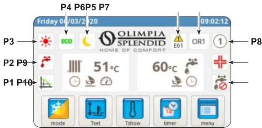
P1. Climatic curve enabled
P2. Production of domestic water in progress
P3. Active mode (standby, cooling, heating, only domestic hot water)
P4. Energy saving function
P5. Night function
P6. Error followed by the corresponding code
P7. Override followed by the corresponding code (the override is not a malfunction report)
P8. Address of the heat pump in case of configuration of various units in cascade mode
P9. Anti-Legionella function in progress
P10. Production of domestic water disabled
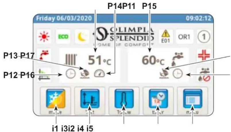
P11. System water temperature
P12. Timer active
P13. Holiday program
P14. Rating active
P15. Domestic water temperature
P16. Timer active
P17. Holiday program
i1. Modes of operation menu
i2. Desired temperature setting
i3. System temperatures
i4. Timer menu
i5. Functions menu
5.2 - HOLIDAY MODE
Press the icon (P13/P17) to display the setting screen of holiday periods.
It is possible to set up to 3 holiday periods in one year.
In this system, the pump anti-blockage and antifreeze protections will remain active (the anti-Legionella function is disabled).
5.3 - NIGHT MODE
Press the icon (P5) to display the screen of the night function activation range.
In this screen it is possible to set the activation range of the function.
Press the icon (i1) to access the menu "mode selection".

Press to start cooling.
heat pump produces cold water until the set temperature is reached (fixed value or dynamic value if the climatic curve is enabled).
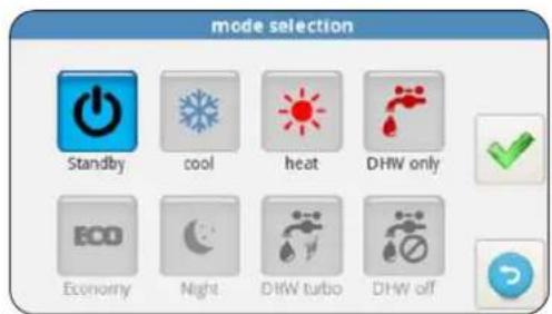

Press to start heating.
heat pump produces hot water until the set temperature is reached (fixed value or dynamic value if the climatic curve is enabled).

Press to start the production of domestic water only.

Press to set the desired temperatures in energy saving mode (ECO values).
The energy saving mode has no effect if the climatic curves are enabled.

Press to enable the night function (limits the power and noise level of the external unit).

Press to enable the production of domestic hot water under any condition of the external temperature using all power available.

Press to disable the production of domestic water

Press to confirm any change to the mode of operation

Press to return to the main menu
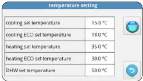
5.5 - TEMPERATURES SETTING
Press the icon (i2) to access the menu "temperature setting".
To change a temperature:
- Press on the value which must be changed.
- A submenu with numeric keypad appears.
-
Change the temperature.
-
Press the icon to confirm.
-
Press the icon to return to the main menu.
The settable temperatures are:
Cooling water temperature
- Cooling water temperature with energy saving function ECO
- Heating water temperature
- Heating water temperature with energy saving function ECO
- Domestic hot water temperature.
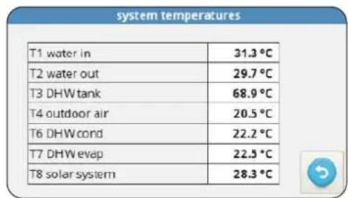
5.6 - SYSTEM TEMPERATURES
Press the icon (i3) to access the menu "system temperatures".
The displayed temperatures are:
- Inlet water temperature (from heating or cooling system)
- Outlet water temperature (to heating or cooling system)
- Domestic hot water (DHW) accumulation temperature
- External air temperature
- Domestic hot water production condenser water temperature (only for AQUADUE models)
- Domestic hot water production evaporator water temperature (only for AQUADUE models)
- Temperature of water from solar thermal system (only if connected)
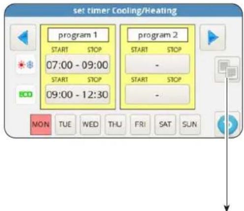
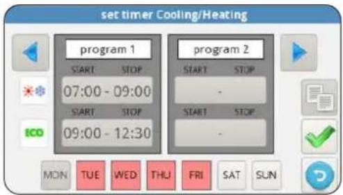
5.7 - TIMER MENU
Press the icon (i4) to access the timer menu.
The available timers are:
Heating/cooling
- Domestic hot water (DHW)
Night function
- Holiday
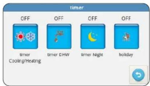
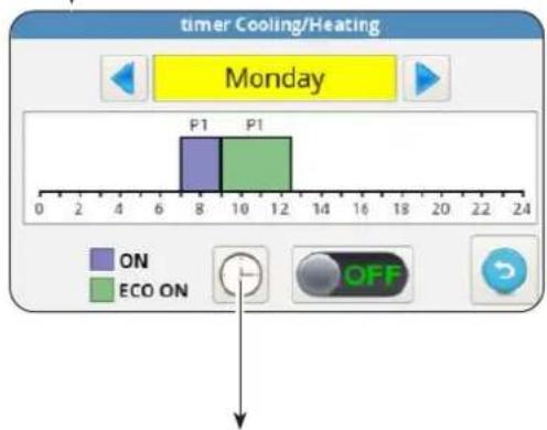
Press on one of the icons to access the setting of the respective timer and the screen relating to the activation range.
In this screen is displayed the programming set for each day of the week.
- To change the displayed day, press on the right arrow (to display the next day) and on the left arrow (to display the previous day).
- To activate or deactivate the timer, press on the icon ON/OFF.
Press on the "clock" icon to access the screen relating to hourly programming.
In this screen it is possible to change the hourly programming of each day.
- To display the eight available programs of the selected day, press on the right (to display the next program) and left arrows (to display the previous program).
- To set the program start time, touch the time under "START".
- To set the program end time, touch the time under "STOP".
- To set the day of the week, touch the icon of the day which must be displayed.
If it is desired to copy programming of one day of the week on the other days:

-
Press the icon located under the right arrow and then select the days in which programming must be copied.
-
Press the icon to confirm.
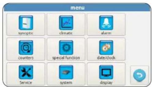
3 - FUNCTIONS MENU
Press the icon (i5) to access the functions menu where it is possible to supervise and configure the heat pump.
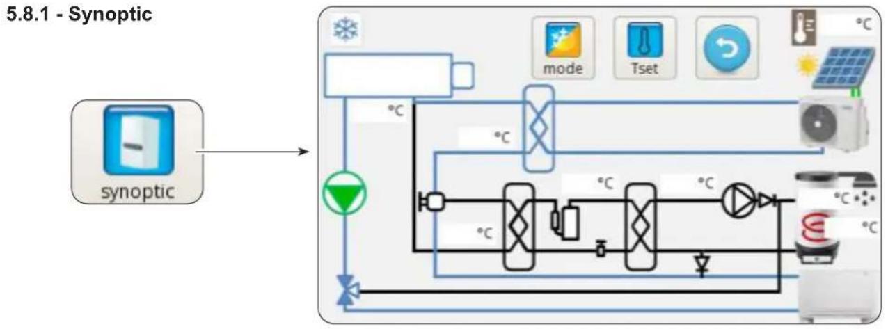
The synoptic shows the system diagram and operating status in real time.
In detail, the synoptic shows:
The current mode of operation
- The modes of operation menu icon
- The desired temperatures setting icon
- The hydraulic circuit and the refrigerating circuit (blue colour indicates cooling in progress, red colour indicates heating in progress)
- Water/refrigerant plate exchanger (black colour if it is switched off)
Electric heaters collector (black colour if the electric heaters are switched off, red colour if they are on)
- Main circuit pump (black colour if the pump is switched off, green colour if it is on)
Three-way valve
- Domestic hot water circuit compressor
- Domestic hot water circuit pump
- Domestic hot water circuit plate exchanger (black colour if it is switched off)
- Photovoltaic contacts input (sun on when contacts are enabled)
- Solar thermal circuit coils
- The fan coil unit (can be switched with the radiant panel symbol by simply touching the fan coil unit icon)
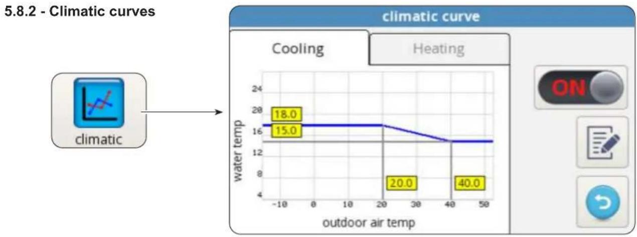
To optimize energy saving, two climatic curves are available, one for heating and one for cooling. These curves allow to adjust water temperature to external air temperature and, therefore, thermal load.
EN-35
The displayed information are:
Cooling and heating climatic curves charts, access to the two climatic curves is carried out by touching the descriptions on top, "COOLING" or "HEATING".
- Values of the setting parameters of each curve.
For each climatic curve it is possible to:
- Activate or deactivate the climatic function by means of the icon ON/OFF.
-
Change the parameters of each curve by pressing on the icon of the parameter, entering a password and the new value.
-
Press the icon to confirm.
The characteristic parameters of each curve are:
- External air temperature for maximum temperature of water
Maximum temperature of water - External air temperature for minimum temperature of water
- Minimum temperature of water.
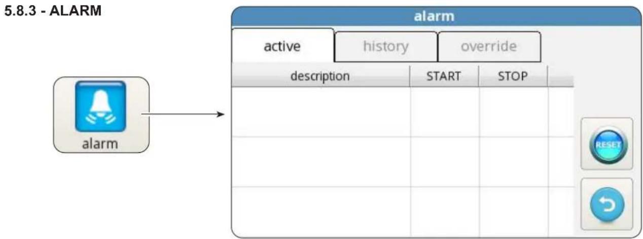
The screen displays the active errors, active overrides and error history.

The overrides DO NOT indicate a malfunction of the system but report a particular operating condition.

In case of error, operation of the heat pump is interrupted.
In this screen:
- Press the button "RESET" and confirm to clear active errors.
- Press the button "RESET" and confirm to reset the active errors history.

| Error code | Error description |
| E01 E01 inlet water temperature sensor faulty | |
| E02 E02 outlet water temperature sensor faulty | |
| E03 E03 DHW temperature sensor faulty | |
| E04 E04 external air temperature sensor faulty | |
| E05 E05 main exchanger antifreeze protection | |
| E06 E6 water flow switch error | |
| E07 E07 UE communication error | |
| E08 E08 disinfection function failed | |
| E09 E09 RS485 communication error | |
| E20 E20 DHW circuit flow switch error | |
| E21 E21 DHW evaporator antifreeze protection | |
| E22 E22 DHW compressor overheating | |
| E23 E23 DHW compressor temperature sensor faulty | |
| E24 E24 DHW condenser temperature sensor faulty | |
| E25 E25 DHW evaporator temperature sensor faulty | |
| E26 E26 solar temperature sensor faulty | |
| E27 E27 display communication error | |
| Override code Override description | |
| OR01 inlet water temperature low | |
| OR02 evaporator antifreeze protection | |
| OR03 external boiler activation request | |
| OR04 TA input open | |
| OR05 UE capacity limitation | |
| OR06 UE defrosting cycle | |
| OR07 UE not available in DHW_B | |
| OR08 DHW flow switch protection | |
| OR09 DHW evaporator antifreeze protection | |
| OR10 DHW compressor temperature protection | |
| OR11 water pump maintenance | |
| OR12 water filter maintenance | |
| OR13 DHW pump maintenance | |
External unit display alarms
On the control board of the external unit is located a display which shows the alarms of the external unit:
| Alarm code Alarm description | |
| E1 02 Power supply phases malfunction (only for 3-phases models) | |
| P6 26 Protection of the frequency conversion module | |
| F1 116 DC voltage too low | |
| HF 54 EEPROM fault of the main board | |
| HH 55 Error H6 has occurred 10 times in 120 minutes | |
| E5 06 Evaporator temperature T3 probe fault | |
| E6 07 External air temperature T4 probe fault | |
| E9 10 Compressor suction temperature Th probe fault | |
| EA 11 Compressor delivery temperature Tp probe fault | |
| P0 20 Low pressure protection | |
| P1 21 High pressure protection | |
| P3 23 Compressor overcurrent protection | |
| P4 24 Compressor delivery temperature Tp protection | |
| Pd 33 Evaporator temperature T3 protection | |
| H0 39 Fault in the communication between UI and UE | |
| H1 40 Fault in the communication between main board and driver board | |
| H6 45 DC fan fault | |
| H7 46 Compressor DC voltage protection fault | |
| H8 47 Pressure sensor fault | |
| HE 53 The fan has worked for 10 minute in Zone A in heating mode | |
| HP 57 The low voltage protection has occurred 3 times in 1 hour in cooling mode | |
| H4 43 P6 protection has occurred 3 times | |
| C7 65 Inverter module overtemperature protection |
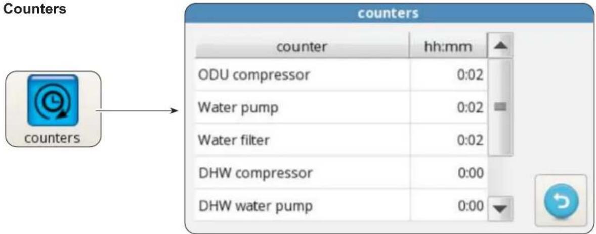
5.8.4 - Counters
The screen shows the hours and minutes of operation of the following components:
- External unit compressor
- Main circuit pump
Water filter - DHW domestic hot water compressor
- DHW domestic hot water circuit pump
- SmartGrid/FTV1
- SmartGrid/FTV2
To reset a counter:
- Select the desired counter.
-
Press the button "RESET" and enter the password.
-
Press the icon to confirm.

5.8.5 - Date / clock
17/03/2020
17:33

The screen shows the set date and time.
To change the set date:
- Select the box with the date.
-
Enter the desired date.
-
Press the icon to confirm.
To change the set time:
- Select the box with the time.
-
Enter the desired time.
-
Press the icon to confirm.
EN-39
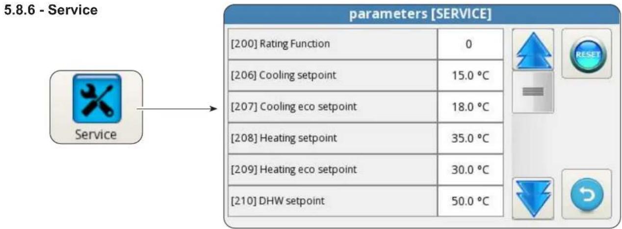
This screen allows to set many and important parameters on which depend the heat pump operation.

Access is governed by password, (installer, service and factory) which allows access to a part or all of the parameters.
By means of the arrows "UP" and "DOWN" it is possible to scroll the list and value of the various parameters.
To set the parameters (ADDR), please refer to the table in the last pages of the manual.


This screen shows the loaded version of the display board software and of the power board software.
- Press the icon to return to the main menu.
EN-40
5.8.8 - Display

This screen allows to select the language, to set the start delay time of the screensaver function and to set the screen brightness.
To change the set language:
- Select the desired language.
- Press the icon to confirm.
To change the start delay time of the screenshot function:
-
Use the arrows "UP" and "DOWN" (box in the top left corner) to increase or decrease the delay time.
-
Press the icon to confirm.
To change the screen brightness:
- Use the arrows "UP" and "DOWN" (box in the bottom left corner) to adjust the screen brightness.
- Press the icon to confirm.
5.8.9 - Special functions
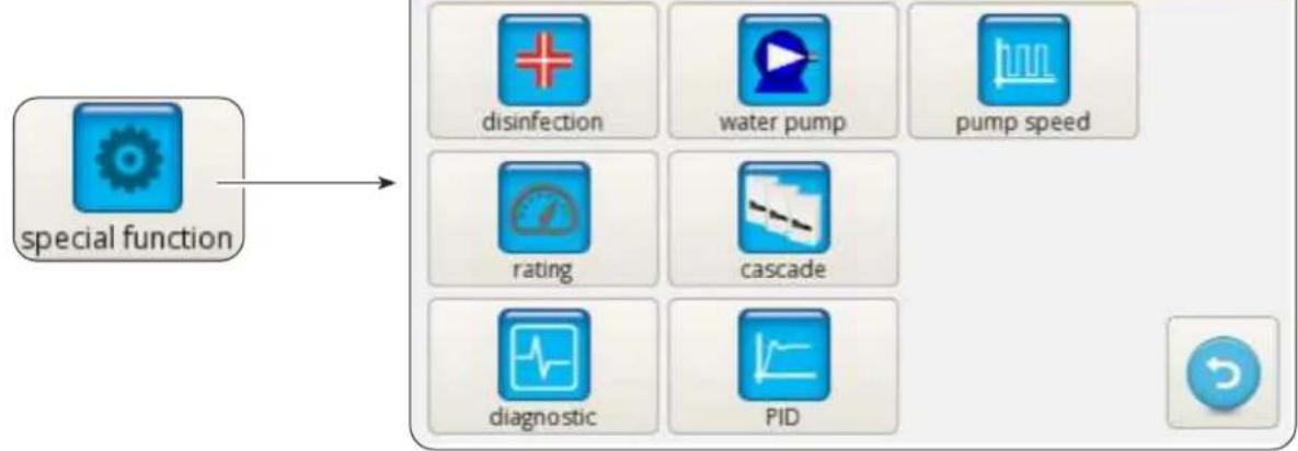
The special functions screen includes a series of functions and controls for configuration and monitoring of the heat pump.

Press it to access mode (with or without additional electric heaters), frequency (from 1 to 30 days), time (from 00:00 to 23:59), disinfection temperature and duration of the disinfection phase setting.

It can be accessed only through installer, service or factory password.

Press to access manual control of the main circuit pump, domestic hot water circuit pump and 3-way valve.

It can be accessed only through installer, service or factory password.

Press to change the main circuit pump speed (from maximum speed 1 to minimum speed 8).

It can be accessed only through installer, service or factory password.

Press to start the fixed frequency mode.

It can be accessed only through service or factory password.

Press to start the cascade operation setting (function not available).

It can be accessed only through service or factory password.

Press to access PID setting.

It can be accessed only through factory password.

Press to access diagnostic function.

It can be accessed only through installer, service or factory password.
The diagnostic screen allows to monitor and change the operating status of the heat pump.
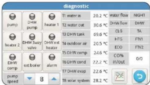
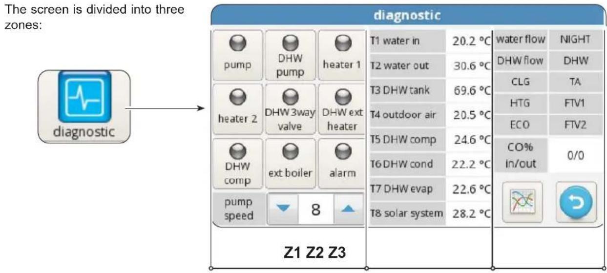
Z1. Activation status of the components connected to the board of the internal unit (red on indicates active status):
- pump: Main circulation pump
- DHW pump: DHW domestic hot water circulation pump
- Heater 1: Heater 1 (Electric heater EH1)
- Heater 2: Heater 2 (Electric heater EH2)
- DHW 3way valve: 3-way valve
- DHW ext heater: DHW domestic hot water accumulation electric heater
- DHW comp: DHW domestic hot water high temperature circuit compressor (only for AQUADUE models)
- Ext boiler: Boiler (Activation of external source of heat)
- Alarm: Alarm
- Pump speed: Main circuit water pump speed

The outputs can be modified from the display if the heat pump is in stand-by mode, otherwise they are in read only mode.
Z2. Visualization of the temperatures measured by the internal unit probes:
T1 water in: system water return temperature
T2 water out: system water delivery temperature
T3 DHW tank: domestic hot water reservoir temperature
T4 outdoor air: external air temperature, only if applicable
- T5 DHW comp: DHW domestic hot water high temperature circuit compressor delivery temperature (only for AQUADUE models)
T6 DHW cond: domestic hot water condenser temperature (only for AQUADUE models)
T7 DHW evap: domestic hot water evaporator temperature (only for AQUADUE models)
T8 solar system: inlet temperature from solar thermal circuit, only if applicable
Z3. Visualization of the internal unit inputs (red on indicates active status):
- FL1 water flow: main water circuit flow switch
- FL2 DHW flow: domestic hot water evaporator circuit flow switch
COOLING ON: cooling mode command (terminal 1 of power board, short with L for activation)
HEATING ON: heating mode command (terminal 2 of power board, short with L for activation) - ECO: desired temperature energy saving command (terminal 3 of power board, short with L for activation)
- NIGHT: night function command (terminal 4 of power board, short with L for activation)
- DHW: request for domestic hot water from external contact (terminal 6 of power board, short with L for activation)
- TA: cooling and heating enabling command (terminal 7 of power board, short with L for activation)
EN-43
- FTV1: input from photovoltaic or smart grid system (terminal 8 of power board, short with L for activation)
- FTV2: input from photovoltaic or smart grid system (terminal 9 of power board, short with L for activation)
CO%: IN / OUT shows IN capacity (supplied by the external unit) and OUT capacity (requested to the external unit)
Press the icon with the diagram to access the trend of the temperatures acquired in the last hour of operation screen.
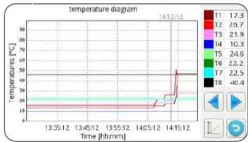
To move inside the diagram:
- Press the right or left arrow to move the cursor.
- Press directly on the diagram to move to the desired position.
5.9 - SOFTWARE UPDATE
In case it is necessary to update the software of the internal unit, proceed as follows:
a. From the System screen, check the software versions of the display board and power board

proceed with the software update only if strictly necessary.
- Each software update entails the rewriting of Service parameters to their factory value. At the end of the updated, all or part of these parameters will have to be manually and opportunistically reconfigured to adapt them to your own system.
b. Empty an USB memory device completely (it must be without files and folders)
c. Load the files listed below in the USB memory device
OLMP_PDCPU2.bin
Update.Fw
Update.fw.md5
updateFw
d. Disconnect all power supplies, of both the internal and external unit
e. Connect the USB memory device in port USB1 of the power board
f. Power the internal unit
g. The power board software update starts automatically. At its completion, the display of the internal unit is operational again.
h. Disconnect all power supplies. Remove the USB memory device.
i. Connect the USB flash drive to port USB2 of the display board
I. Power the internal unit
m. The display board software update starts automatically. At its completion, the display of the internal unit is operational again.
n. Disconnect all power supplies. Remove the USB memory device.
o. Restore all power supplies.
p. Access page MENU -> SERVICE and press "RESET" to update all parameters.
q. From System screen, check that the display and power boards software versions are correct.
r. Access parameters "ADDR370" and "ADDR371" to configure the heat pump correctly.
6 - MANAGEMENT AND CONTROLS
6.1 - INTERNAL UNIT ADDITIONAL ELECTRIC HEATERS MANAGEMENT
The internal unit is equipped with two electric heaters. The electric heaters are enabled to integrate power in heating mode, domestic water production mode, during the execution of the Anti-Legionella cycles or for start-up of the system in case of low temperatures or in building sites for screed drying.
Parameter "ADDR217"
0 = not enabled
1 = one heater enabled for backup
2 = two heaters enabled for backup
3 = one heater enabled for low-temperature start
4 = two heaters enabled for low-temperature start
6.1.1 - Backup
The first electric heater EH1 activates if:
- The heat pump has been in heating mode or domestic hot water production mode for at least ADDR235 minutes.
- The external ambient temperature is lower than ADDR227 degrees Centigrade.
- The delta on water is at least 4^ with respect to the setpoint.
After further 15 minutes from the activation of the first electric heater, if these conditions persist, the second electric heater activates.
The backup function with electric heaters is not active if the external heat source ADDR226 is enabled (ON).
6.1.2 - Low-temperature start
The heaters intervene to ensure start-up even in conditions of low temperature of the hydraulic circuit water (conditions which occur occasionally as, for instance, before start-up of the system or when it is necessary to dry the screed).
Once the hydraulic circuit water reaches a temperature of approximately 12^ , the heaters switch off and normal operation of the heat pump is restored.
6.1.3 - Legionella prevention function
The Legionella prevention function is governed by the parameters from ADDR228 to ADDR233.
The parameter ADDR229 differentiates two macro modes:
ADDR229=0
The Legionella prevention function is obtained by means of the combination of the main heat pump and of an optional electric heater (output K5).
The production of domestic hot water is managed with a temperature probe T3 ADDR228=2 and the Legionella prevention function is enabled (ADDR230>0), then the machine works as follows:
- It starts at the time ADDR231 and every ADDR230 days starts water heating until temperature ADDR232 is reached.
- When the machine reaches temperature ADDR232, it maintains it within 2^ for a time equal to ADDR233; if temperature ADDR232 is not reached within 7 hours from start-up, once 24 hours have elapsed, the machine tries again and the alarm E08 appears at the second failure.
ADDR229=1
The Legionella prevention function is obtained by means of the sole optional electric heater (output K5) and maintains the same modes described in the parameter ADDR229=0.

Output K5 cannot be connected directly to the heater, add an external relay with appropriate electrical specifications.

The Legionella prevention function is carried autonomously from the secondary circuit to R134a.
EN-45
6.2 - REMOTE CONTROL
It is possible to control some functions of the appliance remotely.
Parameter "ADDR220"
0 = remote control disabled
1 = remote control through serial
2 = remote control through free contacts
6.2.1 - Serial
The control from serial is only possible through SIOS CONTROL domotic.
If control from serial is enabled, some functions on the main screen are disabled (mode of operation, timer).
6.2.2 - Free contacts
The connections of the contacts must be carried out on the terminal box of the internal unit electronic board. The contacts must be closed on terminal L.
If control from contacts is enabled, some functions on the main screen are disabled (mode of operation).
| Terminal Description | |
| terminal 1 Cooling mode enabling | |
| terminal 2 Heating mode enabling | |
| terminal 3 ECO setpoint enabling | |
| terminal 4 Night function enabling | |
| terminal 5 COMMON CONNECTED TO N | |
| DHW terminal | DHW input can be connected to a free contact for enabling of domestic hot water production. If ADDR228=1, the production of domestic hot water is disabled with contact open, enabled with contact closed. |
| TA terminal | TA input can be connected to a free contact of a chronothermostat or to the contacts in parallel chiller/boiler of the electronic controls of the fan coils BI2 and BI2+. When the contact is closed, all cooling, heating and domestic water production functions are enabled. When the contact is open, only domestic water production remains active. |
| terminal 8 Input from SMART GRID or photovoltaic FTV1 | |
| terminal 9 Input from SMART GRID or photovoltaic FTV2 | |
Relationship between mode of operation and the main contact inputs:
| Terminal 1 Terminal 2 TA terminal | Description | |
| Open Open Open Standby | ||
| Open Open Closed Standby | ||
| Open Closed Open run and domestic only | ||
| Open Closed Closed run and heating and domestic | ||
| Closed Open Open run and domestic only | ||
| Closed Open Closed run and cooling and domestic |
The internal unit UI is equipped with two inputs for connection to a photovoltaic system. Parameter "ADDR341"
0 = disabled
1 = enabled
When one or both of the FTV inputs are closed, it is possible to automatically force the accumulation of energy by requesting the internal unit to heat more (if in heating mode or in domestic water production) or to cool more (if in cooling mode)
Parameter "ADDR347" cooling water delta
Parameter "ADDR348" heating water delta
Parameter "ADDR349" domestic water delta
6.4 - CHECK OF THE CIRCULATION PUMPS
During installation, the operation of the circulation pump can be forced for 15 minutes from the window on the control display "Pumps"; in that way, air bleeding is eased in the final filling phase of water in the system.
The circulation pump can work in different modes depending on the needs of the system:
- Continuous operation of the pump (parameter ADDR221=OFF=0)
- Switching off upon reaching the desired temperature (parameter ADDR221=ON=1) and sampling every ADDR237 minutes for one minute (parameter ADDR237=10 minutes, the pump will activate for one minute every ten minutes).
When the system is in stand-by or with fulfilled set point, the anti block function of the system and DHW circuit pumps is present; setting the parameter ADDR221 = ON = 1 , the pump is activated every ADDR222 hours for a time equal to ADDR223 seconds).
The parameters above can be set in the window Service.
6.5 - AUXILIARY EXTERNAL HEAT SOURCE MANAGEMENT
In heating or domestic water production mode, set the parameter ADDR226=ON=1 and, if external ambient temperature is lower than ADDR227 degrees centigrade, the control will provide for the replacement of the heat pump with the activation of an output for enabling of an external heat source.
7 - USE
7.1 - PRODUCTION OF DOMESTIC HOT WATER
With SHERPA AQUADUE TOWER, thanks to a water/water integrated in the internal unit heat pump, it is possible to produce domestic hot water at high temperature (up to 75^ ) without the use of electric heaters, in parallel with the conditioning function and independently from external air temperature.
The production of domestic hot water, up to the maximum temperature of the parameter "maximum ACS_A" of parameter ADDR248 is entrusted to the main heat pump (external unit which uses the internal unit main exchanger) by switching the three-way valve in the internal unit.
Once the maximum temperature ACS_A of parameter ADDR248 has been reached, the main heat pump will continue to work in conditioning mode if required and the water/water integrated in the internal unit heat pump will produce domestic hot water until reaching the set point of parameter "Domestic hot water temperature".
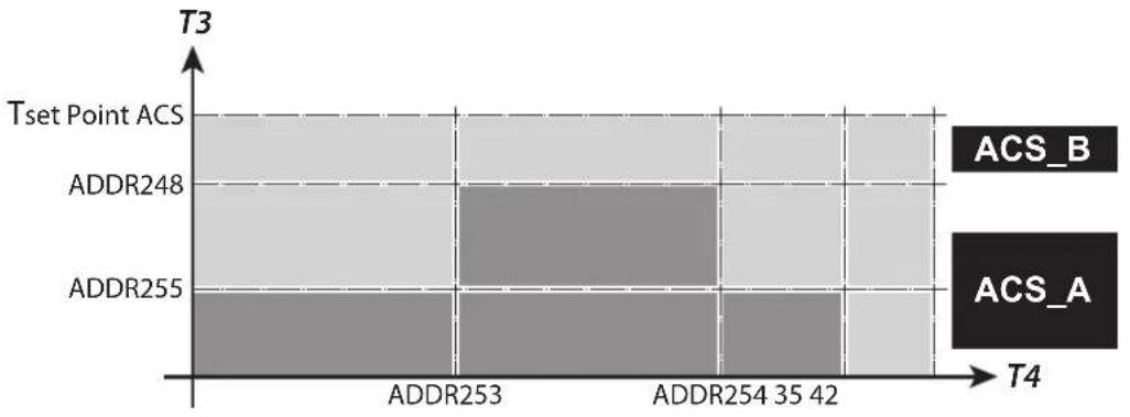

During the production of domestic hot water with the main heat pump, the system produces as much power as possible to quickly meet the request for domestic hot water.
The request for domestic water can occur in the follow manners:
- Through DHW/L contact and setting parameter ADDR228=1; in this case, set the external thermostat at a temperature lower than 70^ .
- Through a temperature sensor inserted in the domestic hot water reservoir setting parameterADDR228=2; in this case, the set point is determined by parameter ADDR210.
With parameter ADDR228 = 0 , the production of domestic hot water is disabled.
With parameter ADDR238 it is possible to change the hysteresis cycle of the domestic water temperature check.

The temperature sensor T3 supplied in the internal module must always be inserted in and connected to the domestic hot water reservoir.
EN-48
7.2 - ANTIFREEZE PROTECTIONS
The brazed plate exchanger of the main circuit and the evaporator of the heat pump for domestic hot water production at high temperature in the internal unit are protected against breaking in case of frost by a flow switch which stops the operation of the system when water flow rate is insufficient and by the temperature sensors on the exchanger.
7.3 - DEACTIVATION AND SWITCHING OFF FOR LONG PERIODS
To deactivate the heat pump, proceed as follows:
- Press the icon Stand by in the display.
- Cut off power to the external unit.

This way, the anti-blocking function of the circulation pump remains active.
The non-use of the heat pump for a long period of time entails that the following operations must be carried out:
- Press the icon Stand by d in the display.
- Disconnect all power supplies of the internal unit through the main switches.
- Disconnect all power supplies of the external unit through the main switches.

To restart the air-water heat pump after a long period of inactivity of the heat pump, it is advised to rely on the Technical Assistance Service.
8 - MAINTENANCE AND CLEANING
8.1 - CLEANING

Before proceeding with any maintenance and cleaning intervention, it is essential to disconnect all the power circuits and/or disconnect all the main switches.
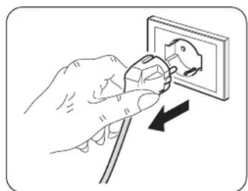
- Cleaning of the sheet steel panels must be carried out only with cloths dampened with water and soap.
- In case of tenacious stains, damp the cloth with a 50% mixture of water and denatured alcohol or with specific products.
- Once cleaning is complete, dry the surfaces with care.

Do not use a chemically treated or antistatic cloth to clean the appliance.
of use gasoline, solvent, polish or similar solvents.
These products could cause the breakage or deformation of the plastic surface.
8.2 - PERIODIC MAINTENANCE
Periodic maintenance is essential in order to maintain the heat pump always efficient, safe and reliable over time. Maintenance can be carried out periodically by the Technical Assistance Service, which is technically authorized and prepared and also has, if necessary, original spare parts available.
EN-49

The maintenance plan that OLIMPIA SPLENDID's Technical Assistance Service or the maintenance technician must respect, with annual periodicity, includes the following operations and checks:
- Expansion vessels pressure check (check pressure on the label of the expansion vessel).
Water circuit filling.
Presence of air in the water circuit. - Efficiency of safety devices.
- Electrical power voltage.
- Electrical absorption.
- Electrical connections tightening.
- Cleaning of fans grilles and external unit battery fins.
- Check for presence of dirt on the metallic net filters.
- Check of the sacrificial anode.
8.2.1 - Check of the domestic hot water reservoir magnesium anode
The magnesium anode is a sacrificial anode which depletes during the use of the domestic hot water reservoir.

The magnesium anode must be subject to visual check at least every two years (ref. standard DIN 4753).
The DHW reservoir of Sherpa Aquadue Tower is equipped with a tester (fig.4 - rif.16) for check of the state of wear of the anode.
For wear check (fig.3-4):
- Remove the front panel (P) of Sherpa Aquadue Tower
- Press the button located on the tester anode (D)

Check the position of the needle, if the needle of the tester positions in the green zone, it is not necessary to replace the magnesium anode.
If it positions in the red zone, it is necessary to replace the anode.
Proceed with the replacement of the anode as described below (Fig.4):
a. Remove the access cap to the anode (C) located on the thermoformed part of the domestic hot water reservoir.
b. Undo the fixing nut (E) by releasing the terminal of the cable + of the tester anode with a 14mm wrench.
c. Unscrew the magnesium anode (F) with a 26mm wrench.
d. Insert the magnesium anode (F) in its seat by closing it hermetically during assembly with a suitable sealant (for example: hemp or PTFE tape) avoiding that the bar enters in contact with oil or grease.

Keep maximum cleaning during the operations inside the domestic hot water reservoir.
e. Check the seal of the reservoir during filling phase with water.
f. Correctly reposition the anode access cap (C).
TABLE DES MATIÈRES GÉNÉRALE
0 - MISES EN GARDE 3
0.1 - INFORMATIONS GENE RALES 3
0.2 - SYMBOLOGIE 3
3.5 - ALARM UMWÄLZPUMPE
Power board: 0.50 - 18/03/2020