Sherpa Tower S3 - Heat pump OLIMPIA SPLENDID - Free user manual and instructions
Find the device manual for free Sherpa Tower S3 OLIMPIA SPLENDID in PDF.

| Product Type | Air-to-water heat pump |
| Brand | Olimpia Splendid |
| Model | Sherpa Tower S3 |
| Power supply | 220-240 V~ 50 Hz (single-phase) / 380-415 V 3N~ 50 Hz (three-phase depending on version) |
| Dimensions (W × H × D) | 4-6 kW: 1008 × 712 × 426 mm; 8-16 kW: 1118 × 865 × 523 mm |
| Net weight | 4-6 kW: 58 kg; 8-10 kW: 75 kg; 12-16 kW: 97 kg (single-phase) / 112 kg (three-phase) |
| Refrigerant | R32, factory charge from 1.50 to 1.84 kg depending on model |
| Nominal power (heating) | From 4 kW to 16 kW depending on version (refer to technical data) |
| Ambient temperature range (heating) | -25 °C to +35 °C |
| Ambient temperature range (cooling) | -5 °C to +43 °C |
| Ambient temperature range (DHW) | -25 °C to +43 °C |
| Compressor | Double rotation DC inverter |
| Fan | DC motor, horizontal |
| Heat exchanger | Finned coil |
| Refrigerant connections | Gas: Ø15.9 mm; Liquid: Ø6.35 mm (4-6 kW) or Ø9.52 mm (8-16 kW) |
| Max piping length | 30 m |
| Max height difference | 20 m |
| Additional refrigerant | Beyond 15 m: 20 g/m (4-6 kW) or 38 g/m (8-16 kW) |
| Electrical protection | 30 mA differential circuit breaker mandatory |
| Routine maintenance | Regular cleaning of the heat exchanger and filter; leak check every 12 months |
| Defrost | Automatic (approx. 2-10 min) |
| Error display | Error code on user interface (full list in manual) |
| Energy efficiency class | Refer to the provided energy label |
Frequently Asked Questions - Sherpa Tower S3 OLIMPIA SPLENDID
User questions about Sherpa Tower S3 OLIMPIA SPLENDID
0 question about this device. Answer the ones you know or ask your own.
Ask a new question about this device
Download the instructions for your Heat pump in PDF format for free! Find your manual Sherpa Tower S3 - OLIMPIA SPLENDID and take your electronic device back in hand. On this page are published all the documents necessary for the use of your device. Sherpa Tower S3 by OLIMPIA SPLENDID.
USER MANUAL Sherpa Tower S3 OLIMPIA SPLENDID
natural_image
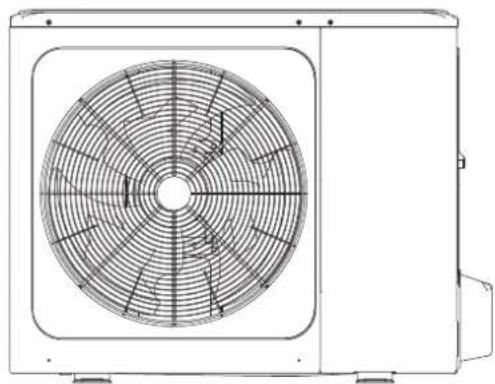
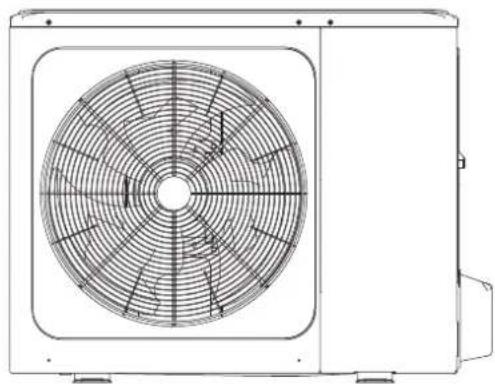
Technical line drawing of a fan or air conditioning unit with concentric circular patterns (no text or symbols)NOTA IMPORTANTE:

natural_image
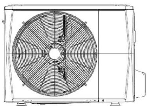
Technical line drawing of a front-mounted air fan with visible blades and mounting feet (no text or symbols)4/6 kW
natural_image
Technical line drawing of a front-mounted air conditioning unit with visible fan blades and mounting bracket (no text or symbols)8/10 kW
natural_image
Technical line drawing of a rectangular industrial enclosure with ventilation grilles and mounting feet (no text or symbols)8/10 kW
natural_image
Warning symbol of a flame inside a triangle (no text or numbers)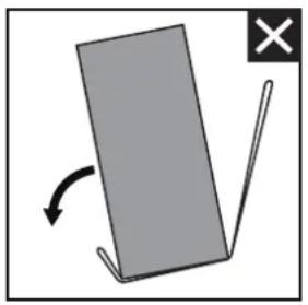
natural_image
Simple diagram showing a gray rectangular object with an arrow indicating rotation and a cross mark (no text or symbols)
natural_image
Simple diagram showing a gray rectangular object with an arrow indicating rotation, no text or symbols present.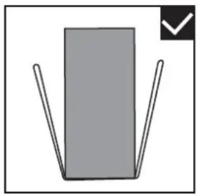
natural_image
Simple diagram of a gray rectangle with two vertical lines and a checkmark in the corner (no text or symbols)natural_image
Two workers carrying a large fan-shaped device with visible blades, no text or symbols presentnatural_image
Technical line drawing of a mechanical fan or vent assembly with no visible text or symbolsFig: 6-4
Fig: 6-6
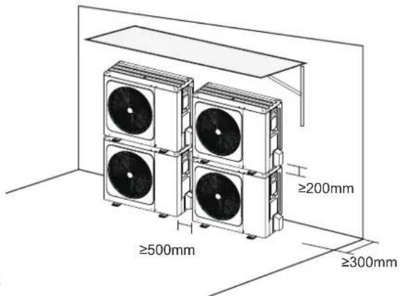
Fig.7-1

ATTENZIONE
In order to avoid the release of cold or heat from the connecting pipeline to the external environment during the operation of the equipment, please take effective insulation measures for the gas pipe and liquid pipe separately
natural_image
Three identical 3D icons showing optical or mechanical components with checkmark and cross symbols, no text or labels present.natural_image
Technical line drawing of a multi-chamber air conditioning unit with fan and cooling unit (no text or symbols)
NOTA
natural_image
Technical line drawing of a four-wheeler electric fan with labeled section 1 (no text or symbols on the fan itself)natural_image
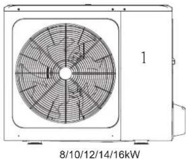
Technical line drawing of a dual-panel air conditioning unit with fan blades and central hub (no text or symbols on the diagram itself)8/10/12/14/16 kW
Fig.11-2

NOTA
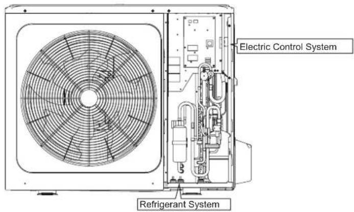
Sherpa S3 E Outdoor Unit
natural_image
Technical line drawing of a circular fan or vent system mounted on an air conditioning unit (no text or symbols)IMPORTANT NOTE:

Thank you very much for purchasing our product,
Before using your unit, please read this manual carefully and keep it for future reference.
CONTENTS
1 SAFETY PRECAUTIONS 02
2 ACCESSORIES 05
• 2.1 Accessories supplied with the unit 05
3 BEFORE INSTALLATION 05
4 IMPORTANT INFORMATION FOR THE REFRIGERANT 06
5 INSTALLATION SITE 07
• 5.1 Selecting a location in cold climates 08
- 5.2 Prevent sunshine 08
6 INSTALLATION PRECAUTIONS 09
- 6.1 Dimensions 09
- 6.2 Installation requirements 09
- 6.3 Drain hole position 10
- 6.4 Installation space requirements 10
7 INSTALLATION OF THE CONNECTING PIPE 11
- 7.1 Rrfrigerant piping 11
- 7.2 Leakage detection 12
• 7.3 Heat insulation 12
- 7.4 Connecting method ...... 13
- 7.5 Remove dirt or water in the pipes 14
• 7.6 Airtight testing 14
- 7.7 Air purge with vacuum pump 14
- 7.8 Refrigerant amount to be added 14
8 OUTDOOR UNIT WIRING 15
• 8.1 Precautions on electrical wiring work 15
• 8.2 Precautions on wiring of power supply 15
• 8.3 Safety device requirement 16
- 8.4 Remove the switch box cover 16
- 8.5 To finish the outdoor unit installation.... 17
9 OVERVIEW OF THE UNIT 17
- 9.1 Disassembling the unit 17
• 9.2 Electronic control box 18 - 9.3 4\~16kW 1-phase units 20
9.4 12\~16kW 3-phase units 22
10 TEST RUNNING 25
11 PRECAUTIONS ON REFRIGERANT LEAKAGE 25
12 TURN OVER TO CUSTOMER 26
• 13.1 Protection equipment 28
• 13.2 About power cut 28
• 13.3 Heating capacity 28
• 13.4 Compressor protection feature 28
• 13.5 Cooling and heating operation 28
• 13.6 Features of heating operation 28
• 13.7 Defrost in the heating operation 28
- 13.8 Error codes 29
14 TECHNICAL SPECIFICATIONS 34
15 INFORMATION SERVICING 36
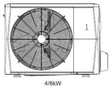
natural_image
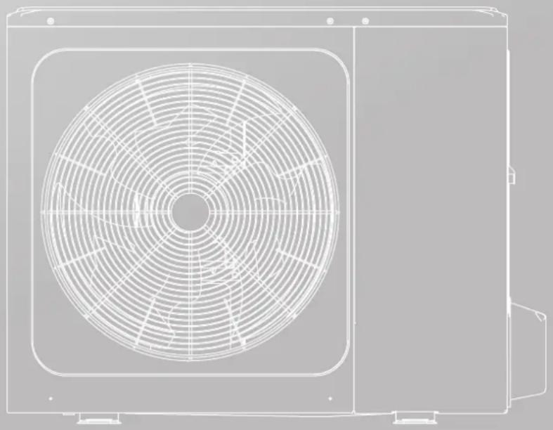
Technical line drawing of a fan with visible blades and central hub (no text or symbols)4/6 kW
natural_image
Technical line drawing of a dual-panel air conditioner unit with fan blades and vent slots (no text or symbols)8/10/12/14/16 kW
Wiring diagram: 8/10kW for example
Please remove the hollow plate after installation.
natural_image
Technical line drawing of a rectangular industrial enclosure with ventilation grilles and mounting feet (no text or symbols)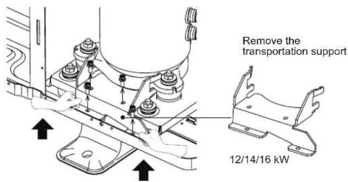
NOTE
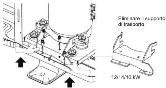
- Please remove the noise insulation cover of the compressor first.
Please make sure the transportation support had been removed.
It will cause heat pump abnormal vibration and noise if running with transportation support for compressor installed.
Please wear gloves when doing the above operation to prevent hand scratches.
Please restore the noise insulation cover after removing the transportation support.
1 SAFETY PRECAUTIONS
The precautions listed here are divided into the following types. They are quite important, so be sure to follow them carefully. Meanings of DANGER, WARNING, CAUTION and NOTE symbols.
i INFORMATION
- Read these instructions carefully before installation. Keep this manual in a handy for future preference.
- Improper installation of equipment or accessories may result in electric shock, short-circuit, leakage, fire or other damage to the equipment. Be sure to only use accessories made by the supplier, which are specifically designed for the equipment and make sure to get installation done by a professional.
- All the activities described in this manual must be carried out by a licensed technician. Be sure to wear adequate personal protection equipment such as gloves and safety glasses while installing the unit or carrying out maintenance activities.
- Contact your dealer for any further assistance.
natural_image
Warning symbol of a flame inside a triangle (no text or numbers)Caution: Risk of fire/ flammable materials
WARNING
Servicing shall only be performed as recommended by the equipment manufacturer. Maintenance and repair requiring the assistance of other skilled personnel shall be carried out under the supervision of the person competent in the use of flammable refrigerants.
DANGER
Indicates an imminently hazardous situation which if not avoided, will result in death or serious injury.
WARNING
Indicates a potentially hazardous situation which if not avoided, could result in death or serious injury.
CAUTION
Indicates a potentially hazardous situation which if not avoided, may result in minor or moderate injury. It is also used to alert against unsafe practices.
NOTE
Indicates situations that could only result in accidental equipment or property damage.
Explanation of symbols displayed on the indoor unit or outdoor unit
 | WARNING | This symbol shows that this appliance used a flammable refrigerant. If the refrigerant is leaked and exposed to an external ignition source, there is a risk of fire. |
 | CAUTION | This symbol shows that the operation manual should be read carefully. |
 | CAUTION | This symbol shows that a service personnel should be handling this equipment with reference to the installation manual. |
 | CAUTION | This symbol shows that a service personnel should be handling this equipment with reference to the installation manual. |
 | CAUTION | This symbol shows that information is available such as the operating manual or installation manual. |
DANGER
• Before touching electric terminal parts, turn off power switch.
- When service panels are removed, live parts can be easily touched by accident.
- Never leave the unit unattended during installation or servicing when the service panel is removed.
- Do not touch water pipes during and immediately after operation as the pipes may be hot and could burn your hands. To avoid injury, give the piping time to return to normal temperature or be sure to wear protective gloves.
- Do not touch any switch with wet fingers. Touching a switch with wet fingers can cause electrical shock.
• Before touching electrical parts, turn off all applicable power to the unit.
WARNING
- Tear apart and throw away plastic packaging bags so that children will not play with them. Children playing with plastic bags face danger of death by suffocation.
- Safely dispose of packing materials such as nails and other metal or wood parts that could cause injuries.
- Ask your dealer or qualified personnel to perform installation work in accordance with this manual. Do not install the unit yourself. Improper installation could result in water leakage, electric shocks or fire
- Be sure to use only specified accessories and parts for installation work. Failure to use specified parts may result in water leakage, electric shocks, fire, or the unit falling from its mount.
- Install the unit on a foundation that can withstand its weight. Insufficient physical strength may cause the equipment to fall and possible injury.
- Perform specified installation work with full consideration of strong wind, hurricanes, or earthquakes. Improper installation work may result in accidents due to equipment falling.
- Make certain that all electrical work is carried out by qualified personnel according to the local laws and regulations and this manual using a separate circuit. Insufficient capacity of the power supply circuit or improper electrical construction may lead to electric shocks or fire.
- Be sure to install a ground fault circuit interrupter according to local laws and regulations. Failure to install a ground fault circuit interrupter may cause electric shocks and fire.
- Make sure all wiring is secure. Use the specified wires and ensure that terminal connections or wires are protected from water and other adverse external forces. Incomplete connection or affixing may cause a fire.
- When wiring the power supply, form the wires so that the front panel can be securely fastened. If the front panel is not in place there could be overheating of the terminals, electric shocks or fire.
• After completing the installation work, check to make sure that there is no refrigerant leakage. - Never directly touch any leaking refrigerant as it could cause severe frostbite. Do not touch the refrigerant pipes during and immediately after operation as the refrigerant pipes may be hot or cold, depending on the condition of the refrigerant flowing through the refrigerant piping, compressor and other refrigerant cycle parts. Burns or frostbite are possible if you touch the refrigerant pipes. To avoid injury, give the pipes time to return to normal temperature or, if you must touch them, be sure to wear protective gloves.
- Do not touch the internal parts (pump, backup heater, etc.) during and immediately after operation. Touching the internal parts can cause burns. To avoid injury, give the internal parts time to return to normal temperature or, if you must touch them, be sure to wear protective gloves.
CAUTION
- Ground the unit.
- Grounding resistance should be according to local laws and regulations.
- Do not connect the ground wire to gas or water pipes, lightning conductors or telephone ground wires.
• Incomplete grounding may cause electric shocks.
- Gas pipes: Fire or an explosion might occur if the gas leaks.
- Water pipes: Hard vinyl tubes are not effective grounds.
- Lightning conductors or telephone ground wires: Electrical threshold may rise abnormally if struck by a lightning bolt.
- Install the power wire at least 3 feet (1 meter) away from televisions or radios to prevent interference or noise. (Depending on the radio waves, a distance of 3 feet (1 meter) may not be sufficient to eliminate the noise.)
- Do not wash the unit. This may cause electric shocks or fire. The appliance must be installed in accordance with national wiring regulations. If the supply cord is damaged, it must be replaced by the manufacturer, its service agent or similarly qualified persons in order to avoid a hazard.
- Do not install the unit in the following places:
- Where there is mist of mineral oil, oil spray or vapors. Plastic parts may deteriorate, and cause them to come loose or water to leak.
- Where corrosive gases (such as sulphurous acid gas) are produced. Where corrosion of copper pipes or soldered parts may cause refrigerant to leak.
- Where there is machinery which emits electromagnetic waves. Electromagnetic waves can disturb the control system and cause equipment malfunction.
- Where flammable gases may leak, where carbon fiber or ignitable dust is suspended in the air or where volatile flammables such as paint thinner or gasoline are handled. These types of gases might cause a fire.
- Where the air contains high levels of salt such as near the ocean.
- Where voltage fluctuates a lot, such as in factories.
- In vehicles or vessels.
-
Where acidic or alkaline vapors are present.
-
This appliance can be used by children 8 years old and above and persons with reduced physical, sensory or mental capabilities or lack of experience and knowledge if they are supervised or given instruction on using the unit in a safe manner and understand the hazards involved. Children should not play with the unit. Cleaning and user maintenance should not be done by children without supervision.
• Children should be supervised to ensure that they do not play with the appliance.
If the supply cord is damaged, it must be replaced by the manufacturer or its service agent or a similarly qualified person.
- DISPOSAL: Do not dispose this product as unsorted municipal waste. Collection of such waste separately for special treatment is necessary. Do not dispose of electrical appliances as municipal waste, use separate collection facilities. Contact your local government for information regarding the collection systems available. If electrical appliances are disposed of in landfills or dumps, hazardous substance can leak into the groundwater and get into the food chain, damaging your health and well-being.
- The wiring must be performed by professional technicians in accordance with national wiring regulation and this circuit diagram. An all-pole disconnection device which has at least 3mm separation distance in all pole and a residual current device(RCD) with the rating not exceeding 30mA shall be incorporated in the fixed wiring according to the national rule.
- Confirm the safety of the installation area (walls, floors, etc.) without hidden dangers such as water, electricity, and gas. Before wiring/pipes.
- Before installation, check whether the user's power supply meets the electrical installation requirements of unit (including reliable grounding, leakage, and wire diameter electrical load, etc.). If the electrical installation requirements of the product are not met, the installation of the product is prohibited until the product is rectified.
- When installing multiple air conditioners in a centralized manner, please confirm the load balance of the three-phase power supply, and multiple units are prevented from being assembled into the same phase of the three-phase power supply.
• Product installation should be fixed firmly, Take reinforcement measures, when necessary.
NOTE
• About Fluorinated Gasses
- This air-conditioning unit contains fluorinated gasses. For specific information on the type of gas and the amount, please refer to the relevant label on the unit itself. Compliance with national gas regulations shall be observed.
- Installation, service, maintenance and repair of this unit must be performed by a certified technician.
- Product uninstallation and recycling must be performed by a certified technician.
- If the system has a leak-detection system installed, it must be checked for leaks at least every 12 months. When the unit is checked for leaks, proper record-keeping of all checks is strongly recommended.
2 ACCESSORIES
2.1 Accessories supplied with the unit
| Installation Fittings | ||
| Name | Shape | Quantity |
| Outdoor unit installation & owners manual (this book) | [0KTH] | 1 |
| Technical data manual | [0ZCK] | 1 |
| Water outlet connection pipe assembly |  | 1 |
3 BEFORE INSTALLATION
• Before installation
Be sure to confirm the model name and the serial number of the unit.
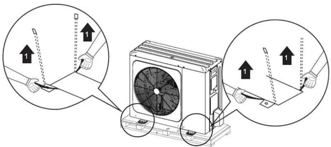
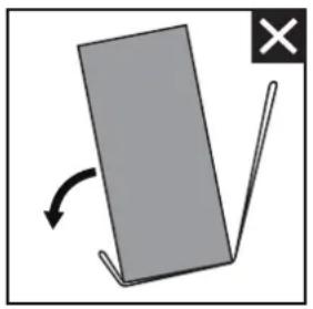
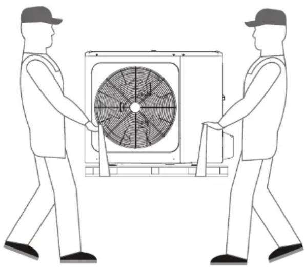
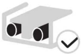
- Handling
- Handle the unit using the sling to the left and the right .Pull up both sides of the sling at the same time to prevent disconnection of the sling from the unit.
natural_image
Simple diagram showing a gray rectangular object with an arrow indicating rotation and a black X mark (no text or symbols)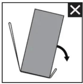
natural_image
Simple diagram showing a gray rectangular object with an arrow indicating rotation, no text or symbols present.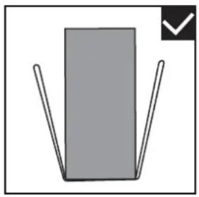
natural_image
Simple diagram of a gray rectangle with two vertical lines and a checkmark in the corner (no text or symbols)- While handling the unit
keep both sides of the sling level.
keep your back straight
natural_image
Two workers carrying a large fan-shaped device with a central fan blade (no text or symbols visible)- After mounting the unit, remove the sling from the unit by pulling 1 side of the sling.
CAUTION
• To avoid injury, do not touch the air inlet and aluminum fins of the unit.
- Do not use the grips in the fan grills to avoid damage.
- The unit is top heavy! Prevent the unit from falling due to improper inclination during handling.
4 IMPORTANT INFORMATION FOR THE REFRIGERANT
This product has the fluorinated gas, it is forbidden to release to air.
Refrigerant type: R32; Volume of GWP: 675.
GWP=Global Warming Potential
| Model | Factory charged refrigerant volume in the unit | |
| Refrigerant/kg | Tonnes CO2 equivalent | |
| 4kW | 1.50 1.02 | |
| 6kW | 1.50 1.02 | |
| 8kW | 1.65 1.11 | |
| 10kW | 1.65 | 1.11 |
| 1-phase 12kW 1.84 1.24 | ||
| 1-phase 14kW | 1.84 1.24 | |
| 1-phase 16kW 1.84 1.24 | ||
| 3-phase 12kW | 1.84 | 1.24 |
| 3-phase 14kW 1.84 1.24 | ||
| 3-phase 16kW | 1.84 | 1.24 |
CAUTION
• Frequency of Refrigerant Leakage Checks
- Equipment that contains less than 3 kg of fluorinated greenhouse gases or hermetically sealed equipment, which is labelled accordingly and contains less than 6 kg of fluorinated greenhouse gases shall not be subject to leak checks.
- For unit that contains fluorinated greenhouse gases in quantities of 5 tonnes of CO2 equivalent or more, but of less than 50 tonnes of CO2 equivalent, at least every 12 months, or where a leakage detection system is installed, at least every 24 months.
- Only certificated person is allowed to do installation, operation and maintenance.
5 INSTALLATION SITE
WARNING
- Be sure to adopt adequate measures to prevent the unit from being used as a shelter by small animals. Small animals making contact with electrical parts can cause malfunction, smoke or fire. Please instruct the customer to keep the area around the unit clean.
- Select an installation site where the following conditions are satisfied and one that meets with your customer's approval.
- Places that are well-ventilated.
- Places where the unit does not disturb next-door neighbors.
- Safe places which can bear the unit's weight and vibration and where the unit can be installed at an even level.
- Places where there is no possibility of flammable gas or product leak.
- The equipment is not intended for use in a potentially explosive atmosphere.
- Places where servicing space can be well ensured.
- Places where the units' piping and wiring lengths come within the allowable ranges.
- Places where water leaking from the unit cannot cause damage to the location (e.g. in case of a blocked drain pipe).
- Places where rain can be avoided as much as possible.
- Do not install the unit in places often used as a work space. In case of construction work (e.g. grinding etc.) where a lot of dust is created, the unit must be covered.
- Do not place any object or equipment on top of the unit (top plate)
- Do not climb, sit or stand on top of the unit.
- Be sure that sufficient precautions are taken in case of refrigerant leakage according to relevant local laws and regulations.- Don't install the unit near the sea or where there is corrosion gas.
- When installing the unit in a place exposed to strong wind, pay special attention to the following.
- Strong winds of 5 m/sec or more blowing against the unit's air outlet causes a short circuit (suction of discharge air), and this may have the following consequences:
- Deterioration of the operational capacity.
- Frequent frost acceleration in heating operation.
- Disruption of operation due to rise of high pressure.
- Motor burnout.
- When a strong wind blows continuously on the front of the unit, the fan can start rotating very fast until it breaks.
In normal condition, refer to the figures below for installation of the unit:
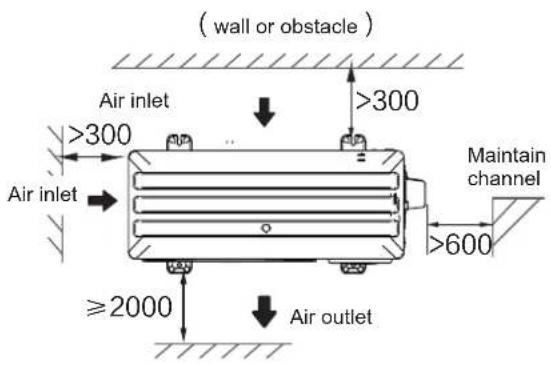

4/6/8/10/12/14/16 kW (unit: mm)
NOTE
- Make sure there is enough space to do the installation. Set the outlet side at a right angle to the direction of the wind.
• Prepare a water drainage channel around the foundation, to drain waste water from around the unit - If water does not easily drain from the unit, mount the unit on a foundation of concrete blocks, etc. (the height of the foundation should be about 100 mm .(in Fig:6-3)
- When installing the unit in a place frequently exposed to snow, pay special attention to elevate the foundation as high as possible.
- If you install the unit on a building frame, please install a waterproof plate (field supply) (about 100mm, on the underside of the unit) in order to avoid drain water dripping. (See the picture in the right).
5.1 Selecting a location in cold climates
Refer to "Handling" in section "4 Before installation"
NOTE
When operating the unit in cold climates, be sure to follow the instructions described below.
- To prevent exposure to wind, install the unit with its suction side facing the wall.
- Never install the unit at a site where the suction side may be exposed directly to wind.
- To prevent exposure to wind, install a baffle plate on the air discharge side of the unit.
- In heavy snowfall areas, it is very important to select an installation site where the snow will not affect the unit. If lateral snowfall is possible, make sure that the heat exchanger coil is not affected by the snow (if necessary construct a lateral canopy).
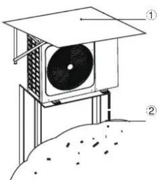
① Construct a large canopy.
② Construct a pedestal.
Install the unit high enough off the ground to prevent it from being buried in snow.
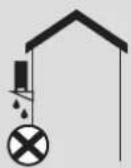
5.2 Prevent sunshine
As the outdoor temperature is measured via the outdoor unit air thermistor, make sure to install the outdoor unit in the shade or a canopy should be constructed to avoid direct sunlight, so that it is not influenced by the sun's heat, otherwise protection may be possible to the unit.
WARING
Uncovered scene, anti-snow shed must be installed: (1) to prevent rain and snow from hitting the heat exchanger, resulting in poor heating capacity of the unit, after long time accumulation, the heat exchanger freezes; (2) To prevent the outdoor unit air thermistor from being exposed to the sun, resulting in failure to boot; (3) To prevent freezing rain.
6 INSTALLATION PRECAUTIONS
6.1 Dimensions
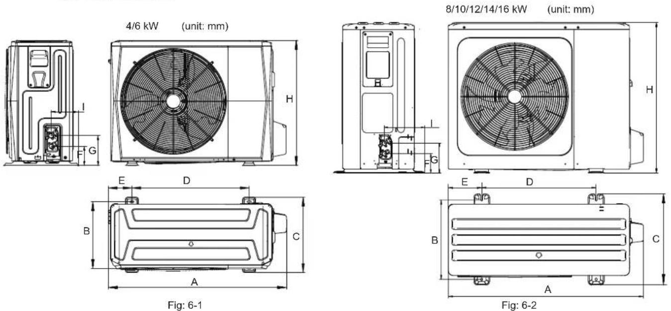
| Model A B C | D E F G H I | ||||||||
| 4/6kW | 1008 | 375 | 426 | 663 | 134 | 110 | 170 | 712 | 160 |
| 8/10/12/14/16kW | 1118 | 456 | 523 | 656 | 191 | 110 | 170 | 865 | 230 |
6.2 Installation requirements
- Check the strength and level of the installation ground so that the unit may not cause any vibrations or noise during the operation.
- In accordance with the foundation drawing in the figure, fix the unit securely by means of foundation bolts. (Prepare four sets each of 10 Expansion bolts, nuts and washers which are readily available in the market.)
- Screw in the foundation bolts until their length is 20 mm from the foundation surface.
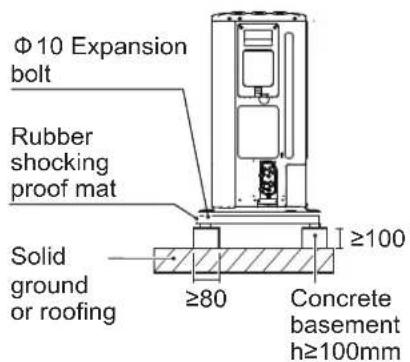
(unit: mm)
Fig: 6-3
natural_image
Technical line drawing of a mechanical fan or vent assembly with no visible text or symbolsFig: 6-4
6.3 Drain hole position
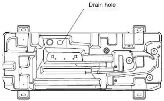
4/6 kW
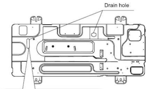
This drain hole is covered by rubber plug. If the small drain hole can not meet the drainage requirements, the big one can be used at the same time.
8/10/12/14/16 kW
Fig: 6-5
CAUTION
It's necessary to install an electrical heating belt if water can't drain out in cold weather even the big drain hole has opened.
It is suggested to site the unit with the base electric heater.
6.4 Installation space requirements
6.4.1 In case of stacked installation
1) In case obstacles exist in front of the outlet side. 2) In case obstacles exist in front of the air inlet.
| Unit | A(mm) |
| 4~16kW | ≥2000 |
Fig: 6-6
NOTE
It's necessary to install the water outlet connection pipe assembly if the unit is mounted on the top of each other, preventing condensate flow to the heat exchanger.
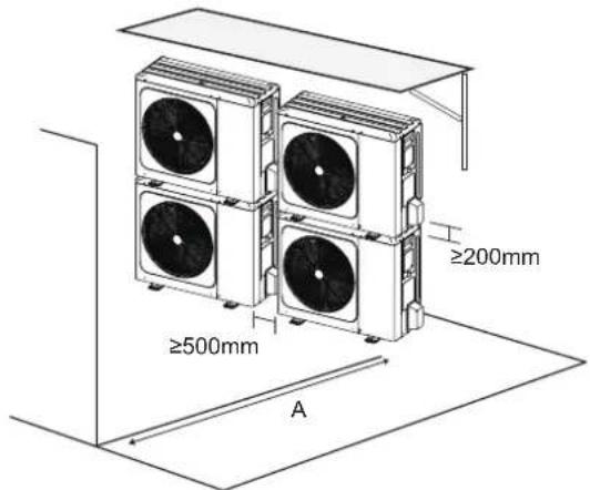
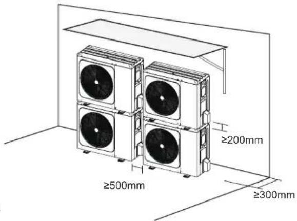
6.4.2 In case of multiple-row installation
1) In case of installing one unit per row.
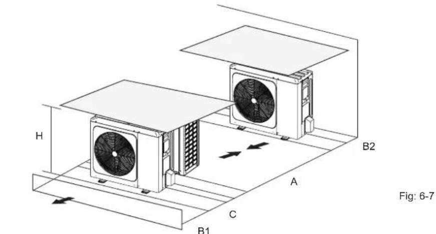
| Unit A(mm) B1(mm) B2(mm) C(mm) | |||||
| 4~16kW | ≥3000 | ≥2000 | ≥150 | ≥600 | |
2) In case of installing multiple units in lateral connection per row.
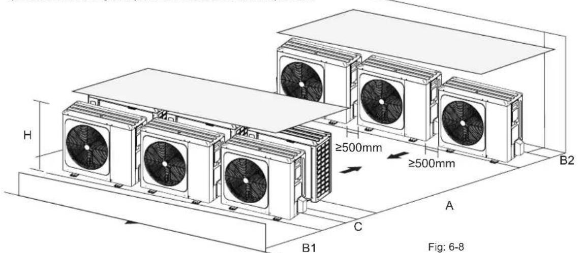
| Unit | A(mm) B1 (mm) B2(mm) C(mm) | |
| 4~16kW | ≥3000 ≥2000 ≥300 ≥600 |
7 INSTALLATION OF THE CONNECTING PIPE
7.1 Refrigerant piping
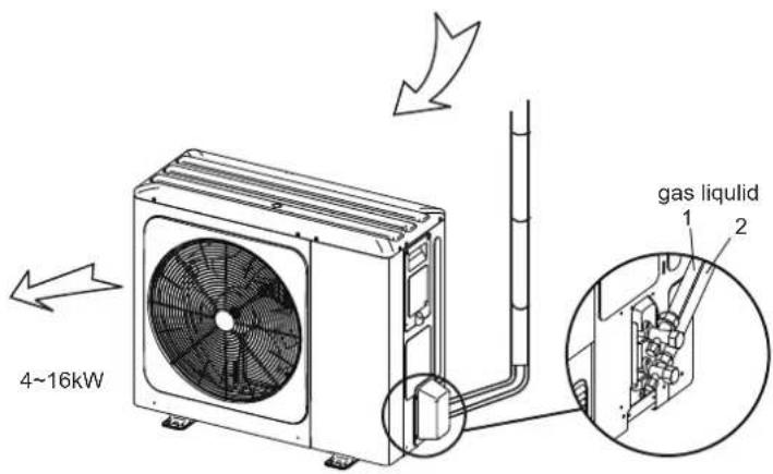
Fig.7-1

CAUTION
- Please pay attention to avoid the components where it is connecting to the connecting pipes.
- To prevent the refrigerant piping from oxidizing inside when welding, it is necessary to charge nitrogen, or oxide will chock the circulation system.
7.2 Leakage detection
Use soap water or leakage detector to check every joint whether leak or not (Refer to Fig.7-2). Note:
A is high pressure side stop valve
B is low pressure side stop valve
C and D is connecting pipes interface of indoor and outdoor units
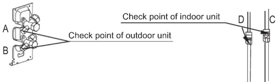
Fig.7-2
7.3 Heat insulation
In order to avoid the release of cold or heat from the connecting pipeline to the external environment during the operation of the equipment, please take effective insulation measures for the gas pipe and liquid pipe separately
1) The gas side pipe should use closed cell foamed insulation material, which the fire-retardant is B1 grade and the heat resistance over 120 °C.
2) When the external diameter of copper pipe≤Φ12.7mm, the thickness of the insulating layer at least more than 15mm; When the external diameter of copper pipe≥Φ15.9mm, the thickness of the insulating layer at least more than 20mm.
3) Please use attached heat-insulating materials do the heat insulation without clearance for the connecting parts of the indoor unit pipes.
7.4 Connecting method
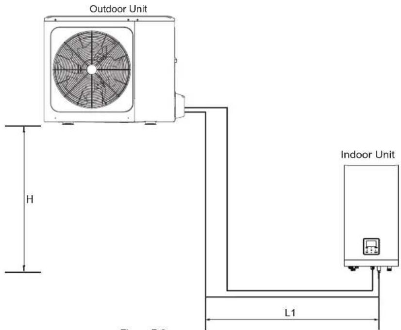
Figure 7-3
| Models | 4~16 kW |
| Max.piping length (H+L1) | 30m |
| Max difference in height (H) | 20m |
1) Size of pipes of Gas side and Liquid side
| MODEL | Refrigerant | Gas side/Liquid side |
| 4/6kW | R32 | 15.9/ 6.35 |
| 8/10kW | R32 | 15.9/ 9.52 |
| 1-phase 12/14/16kW | R32 | 15.9/ 9.52 |
| 3-phase 12/14/16kW | R32 | 15.9/ 9.52 |
2) Connection method
| Gas side | Liquid side | |
| 4~16kW outdoor unit | FlaringFlaring | |
| Indoor unit | FlaringFlaring |
7.5 Remove dirt or water in the pipes
1) Make sure there is no any dirt or water before connectiong the piping to the outdoor and indoor units.
2) Wash the pipes with high pressure nitrogen, never use refrigerant of outdoor unit.
7.6 Airtight testing
Charge pressured nitrogen after connecting indoor/outdoor unit pipes to do airtight testing.

CAUTION
Pressured nitrogen [4.3MPa (44kg/cm ^2 ) for R32] should be used in the airtight testing.
Tighten high/low pressure valves before charging pressured nitrogen.
Charge pressure nitrogen from the connector on the pressure valves.
The airtight testing should never use any oxygen, flammable gas or poisonous gas.
7.7 Air purge with vacuum pump
1) Using vacuum pump to do the vacuum, never using refrigerant to expel the air.
2) Vacuuming should be done from liquid side.
7.8 Refrigerant amount to be added
Calculate the added refrigerant according to the diameter and the length of the liquid side pipe of the outdoor unit/indoor unit connection. If the length of the liquid side pipe is less than 15 meters it is no need to add more refrigerant, so than calculating the added refrigerant the length of the liquid side pipe must subtract 15 meters.
| Refrigerant to be added Model | Total liquid pipe length L(m) | ||
| ≤slant 15m >15m | |||
| Total additional refrigerant | 4/6kW 0g (L-15) × 20g | ||
| 8/10/12/14/16kW 0g (L-15) × 38g | |||
8 OUTDOOR UNIT WIRING

WARNING
A main switch or other means of disconnection, having a contact separation in all poles, must be incorporated in the fixed wiring in accordance with relevant local laws and regulations. Switch off the power supply before making any connections. Use only copper wires. Never squeeze bundled cables and make sure they do not come in contact with the piping and sharp edges. Make sure no external pressure is applied to the terminal connections. All field wiring and components must be installed by a licensed electrician and must comply with relevant local laws and regulations.
The field wiring must be carried out in accordance with the wiring diagram supplied with the unit and the instructions given below.
Be sure to use a dedicated power supply. Never use a power supply shared by another appliance.
Be sure to establish a ground. Do not ground the unit to a utility pipe, surge protector, or telephone ground. Incomplete grounding may cause electrical shock.
Be sure to install a ground fault circuit interrupter (30 mA). Failure to do so may cause electrical shock.
Be sure to install the required fuses or circuit breakers.
8.1 Precautions on electrical wiring work
• Fix cables so that cables do not make contact with the pipes (especially on the high pressure side).
- Secure the electrical wiring with cable ties as shown in figure so that it does not come in contact with the piping, particularly on the high-pressure side.
• Make sure no external pressure is applied to the terminal connectors.
- When installing the ground fault circuit interrupter make sure that it is compatible with the inverter (resistant to high frequency electrical noise) to avoid unnecessary opening of the ground fault circuit interrupter.

NOTE
The ground fault circuit interrupter must be a high-speed type breaker of 30 mA (<0.1 s).
- This unit is equipped with an inverter. Installing a phase advancing capacitor not only will reduce the power factor improvement effect, but also may cause abnormal heating of the capacitor due to high-frequency waves. Never install a phase advancing capacitor as it could lead to an accident.
8.2 Precautions on wiring of power supply
- Use a round crimp-style terminal for connection to the power supply terminal board. In case it cannot be used due to unavoidable reasons, be sure to observe the following instructions.
- Do not connect different gauge wires to the same power supply terminal. (Loose connections may cause overheating.)
- When connecting wires of the same gauge, connect them according to the figure below.
natural_image
Simple icon of two cylindrical objects inside a container with a checkmark (no text or symbols)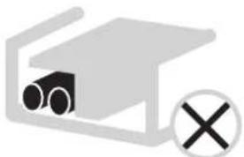
natural_image
Simple diagram of a device with pipes and a cross symbol (no text or labels)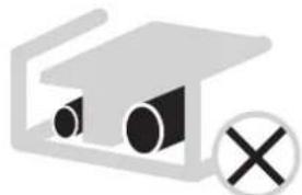
natural_image
Simple line drawing of a graduation cap with two eyes and a cross symbol (no text or labels)- Use the correct screwdriver to tighten the terminal screws. Small screwdrivers can damage the screw head and prevent appropriate tightening.
• Over-tightening the terminal screws can damage the screws. - Attach a ground fault circuit interrupter and fuse to the power supply line.
- In wiring, make certain that prescribed wires are used, carry out complete connections, and fix the wires so that outside force cannot affect the terminals.
8.3 Safety device requirement
- Select the wire diameters( minimum value) individually for each unit based on the table 8-1 and table 8-2, where the rated current in table 8-1 means MCA in table 8-2. In case the MCA exceeds 63A, the wire diameters should be selected according to the national wiring regulation.
- Select circuit breaker that having a contact separation in all poles not less than 3 mm providing full disconnection, where MFA is used to select the current circuit breakers and residual current operation breakers:
Table 8-1
| Rated current of appliance: (A) | Nominal cross-sectional area ( mm^2 ) | |
| Flexible cords | Cable for fixed wiring | |
| ≤3 | 0.5 and 0.75 | 1 and 2.5 |
| >3 and ≤6 | 0.75 and 1 | 1 and 2.5 |
| >6 and ≤10 | 1 and 1.5 | 1 and 2.5 |
| >10 and ≤16 | 1.5 and 2.5 | 1.5 and 4 |
| >16 and ≤25 | 2.5 and 4 | 2.5 and 6 |
| >25 and ≤32 | 4 and 6 | 4 and 10 |
| >32 and ≤50 | 6 and 10 | 6 and 16 |
| >50 and ≤63 | 10 and 16 | 10 and 25 |
Table 8-2
| System | Outdoor Unit Power Current Compressor OFM | ||||||||||
| Voltage (V) | Hz Min. (V) | Max. (V) | MCA (A) | TOCA (A) | MFA (A) | MSC (A) | RLA (A) | KW FLA | (A) | ||
| 4kW | 220-240 | 50 | 198 | 264 | 12 | 18 | 25 | - | 11.50 | 0.10 | 0.50 |
| 6kW | 264 25 | 220-240 | 50 198 | - | 13.50 | 0.10 | 0.50 | ||||
| 8kW | 19264 | 25220-240 | - 50 198 | 14.50 | 0.17 | 1.5016 | |||||
| 10kW | 26419 | 25220 | 240 50 | - | 15.50 | 0.17 | 1.50 | ||||
| 12kW | 220-240 | 50 | 198 | 264 | 25 30 | 35 | - | 23.50 | 0.17 | 1.50 | |
| 14kW | 220-240 | 50 | 198 | 264 | 26 30 | 35 | - | 24.50 | 0.17 | 1.50 | |
| 16kW | 220-240 | 50 | 198 | 264 | 27 30 | 35 | - | 25.50 | 0.17 | 1.50 | |
| 12kW 3-PH | 380-415 | 50 | 342 | 456 | 10 14 | 16 | - | 9.15 | 0.17 | 1.50 | |
| 14kW 3-PH | 380-415 | 50 | 342 | 456 | 11 14 | 16 | - | 10.15 | 0.17 | 1.50 | |
| 16kW 3-PH | 380-415 | 50 | 342 | 456 | 12 14 | 16 | - | 11.15 | 0.17 | 1.50 | |

NOTE
MCA : Min. Circuit Amps. (A)
TOCA : Total Over-current Amps. (A)
MFA : Max. Fuse Amps. (A)
MSC : Max. Starting Amps. (A)
RLA: In nominal cooling or heating test condition, the input Amps of compressor where MAX. Hz can operate Rated Load Amps. (A);
KW : Rated Motor Output
FLA : Full Load Amps. (A)
8.4 Remove the switch box cover
| Unit | 4kW | 6kW | 8kW | 10kW | 12kW | 14kW | 16kW | 12kW 3-PH | 14kW 3-PH | 16kW 3-PH |
| Maximum overcurrent protector(MOP)(A) | 18 | 18 | 19 | 19 | 30 | 30 | 30 | 14 | 14 | 14 |
| Wiring size( mm^2 ) | 4.0 | 4.0 | 4.0 | 4.0 | 6.0 | 6.0 | 6.0 | 2.5 | 2.5 | 2.5 |
- Stated values are maximum values (see electrical data for exact values).
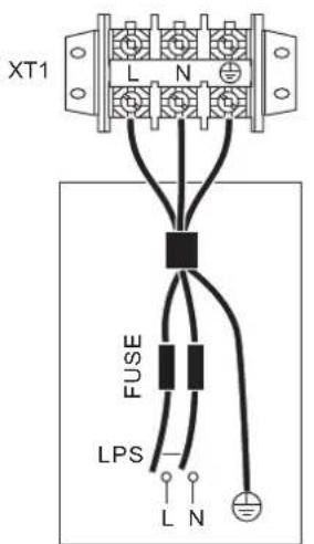
OUTDOOR UNIT
POWER SUPPLY
1-phase 3-phase
XT1
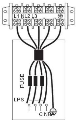
OUTDOOR UNIT POWER SUPPLY
natural_image
Technical line drawing of a multi-chamber air conditioning unit with fan and cooling unit (no text or symbols)
NOTE
The ground fault circuit interrupter must be a high-speed type breaker of 30 mA (<0.1 s).
Please use 3-core shielded wire.
8.5 To finish the outdoor unit installation
insulate and fix the refrigerant piping and interconnection cable as follows:
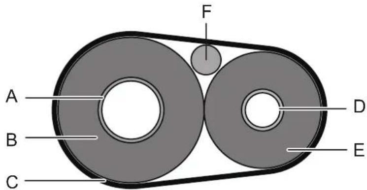
| A | Gas pipe |
| B | Gas pipe insulation |
| C | Finishing tipe |
| D | Liquid pipe |
| E | Liquid pipe insulation |
| F | Interconnection cable |
9 OVERVIEW OF THE UNIT
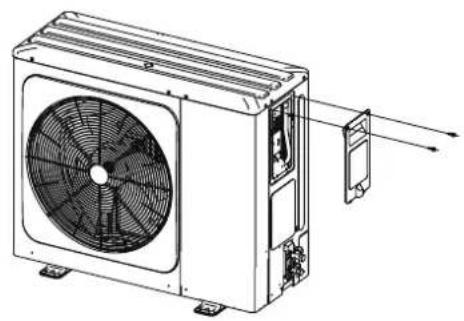
9.1 Disassembling the unit
natural_image
Technical line drawing of a four-wheeler electric fan with labeled component (no text or symbols beyond label)Door 1 To access to the compressor and electrical parts
natural_image
Technical line drawing of a dual-panel air conditioning unit with fan blades and central hub (no text or symbols on the diagram itself)Door 1 To access to the compressor and electrical parts.

WARNING
- Cut off all power supply—i.e. unit power supply and backup heater and domestic hot water tank power supply (if applicable)—before removing doors 1.
- Parts inside the unit may be hot.
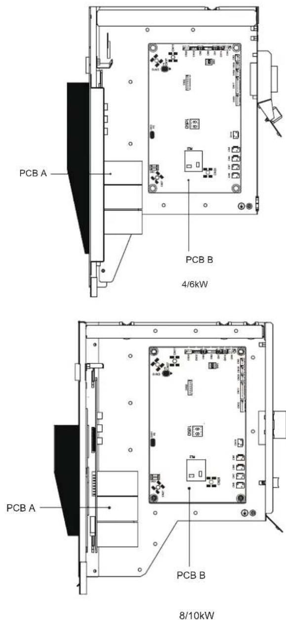
9.2 Electronic control box
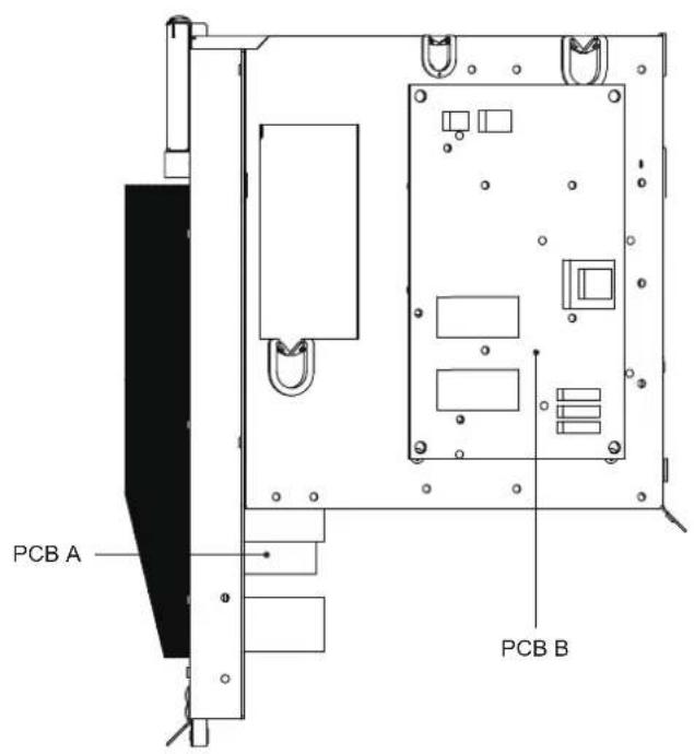
12/14/16kW 1-phase
12/14/16kW 3-phase
NOTE
The picture is for reference only, please refer to the actual product.
9.3 4\~16kW 1-phase units
1) PCB A, 4-10kw, Inverter module
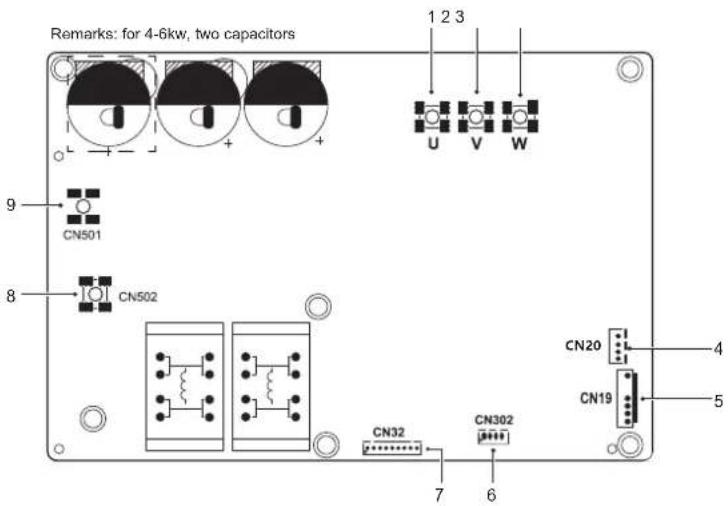
| Assembly unit Assembly unitCode | Code | ||
| 1 | Compressor connection port U | 6 | Reserved(CN302) |
| 2 | Compressor connection port V | 7 | Port for communication with PCB B(CN32) |
| 3 | Compressor connection port W | 8 | Input port N for rectifier bridge(CN502) |
| 4 | Output port for +12V/9V(CN20) | 9 | Input port L for rectifier bridge(CN501) |
| 5 | Port for fan(CN19) | / | / |
2) PCB A, 12-16kw, Inverter module
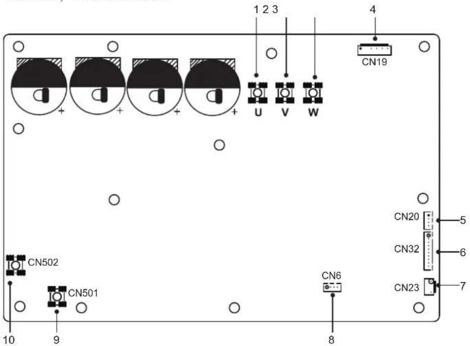
| Assembly unit Assembly unitCode | Code | ||
| 1 | Compressor connection port U | 6 | Port for communication with PCB B(CN32) |
| 2 | Compressor connection port V | 7 | Port for high pressure switch (CN23) |
| 3 | Compressor connection port W Reserved(CN5) | ||
| 4 | Port for fan(CN19) | 9 | Input port L for rectifier bridge(CN501) |
| 5 | Output port for +12V/9V(CN20) | 10 | Input port N for rectifier bridge(CN502) |
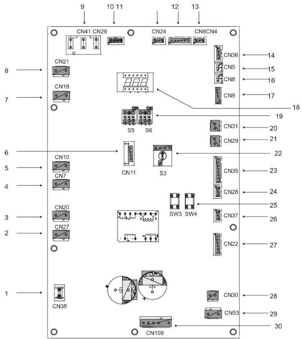
3) PCB B, 4-16kw, Main control board
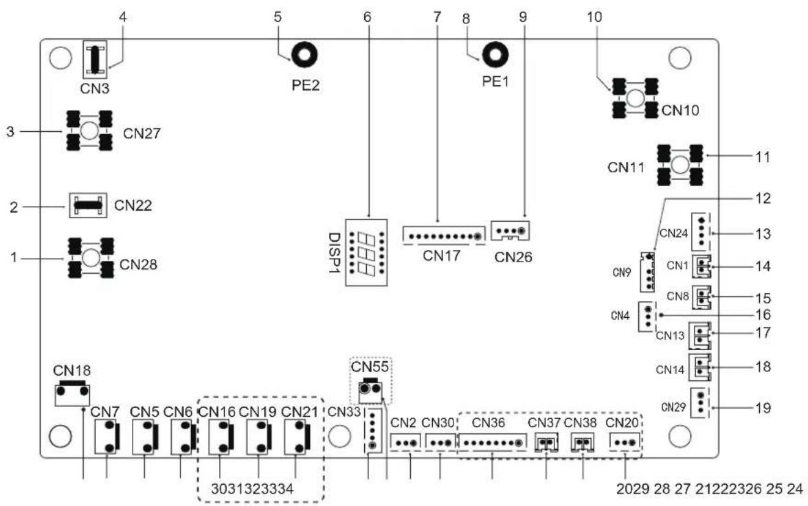
| Code | Assembly unit Assembly unitCode | ||
| 1 | Output port L to PCB A(CN28) | 18 | Port for low pressure switch (CN14) |
| 2 | Reserved(CN22) | 19 | Port for communication with hydro-box control board (CN29) |
| 3 | Output port N to PCB A(CN27) | 20 | Reserved(CN20) |
| 4 | Reserved(CN3) | 21 | Reserved(CN38) |
| 5 | Port for ground wire(PE2) | 22 | Reserved(CN37) |
| 6 | Digital display(DSP1) | 23 | Reserved(CN36) |
| 7 | Port for communication with PCB A(CN17) | 24 | Port for communication(reserved,CN30) |
| 8 | Port for ground wire(PE1) | 25 | Port for communication(reserved,CN2) |
| 9 | Reserved(CN26) | 26 | Reserved(CN55) |
| 10 | Input port for neutral wire(CN10) | Port for electrical expansion valve(CN33)27 | |
| 11 | Input port for live wire(CN11) | 28 | Reserved(CN21) |
| 12 | Port for outdoor ambient temp. sensor and condenser temp.sensor(CN9) | 29 | Reserved(CN19) |
| 13 | Input port for +12V/9V(CN24) | 30 | Port for chassis electrical heating tape(CN16) (optional) |
| 14 | Port for sunction temp.sensor(CN1) | 31 | Port for 4-way valve(CN6) |
| 15 | Port for discharge temp.sensor(CN8) | 32 | Port for SV6 valve(CN5) |
| 16 | Port for pressure sensor(CN4) | 33 | Port for compressor eletric heating tape 1(CN7) |
| 17 | Port for high pressure switch (CN13) | 34 | Port for compressor eletric heating tape 2(CN18) |
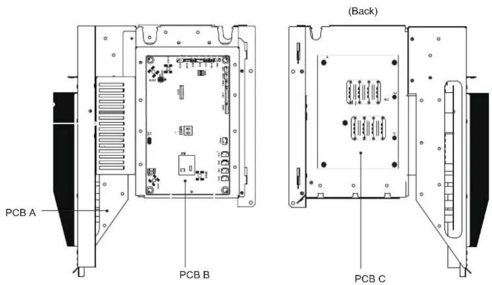
9.4 12\~16kW 3-phase units
1) PCB A, Inverter module
| Assembly unit Assembly unitCode | Code | ||
| 1 | Output port for +15V(CN20) | 8 | Power Input port L1(CN16) |
| 2 | Compressor connection port W(CN19) | 9 | Input port P_in for IPM module(CN1) |
| 3 | Compressor connection port V(CN18) | 10 | Port for communication with PCB B (CN8) |
| 4 | Compressor connection port U(CN17) | 11 | PED board(CN22) |
| 5 | Power Input port L3(CN15) | 12 | Port for high pressure switch (CN23) |
| 6 | Power Input port L2(CN7) | 13 | Port for communication with PCB C(CN2) |
| 7 | Input port P_out for IPM module(CN5) |
2) PCB B, Main control board
| Code | Assembly unit | Code | Assembly unit |
| 1 | Port for ground wire(CN38) | 16 | Port for temp.sensor Tp(CN8) |
| 2 | Port for 2-way valve 6(CN27) | 17 | Port for outdoor ambient temp. sensor and condenser temp.sensor(CN9) |
| 3 | Port for 2-way valve 5(CN20) | 18 | Digital display(DSP1) |
| 4 | Port for eletric heating tape2(CN7) | 19 | DIP switch(S5,S6) |
| 5 | Port for eletric heating tape1(CN10) | 20 | Port for low pressure switch(CN31) |
| 6 | Reserved(CN11) | 21 | Port for high pressure switch and quick check(CN29) |
| 7 | Port for 4-way valve(CN18) | 22 | Rotary dip switch(S3) |
| 8 | Reserved(CN21) | 23 | Port for temp.sensors(TW_out, TW_in, T1, T2,T2B )(CN35)(Reserved) |
| 9 | Power supply port from PCB C(CN41) | 24 | Port for communication XYE(CN28) |
| 10 | Port for communication with Power Meter(CN26) | 25 | Key for force cool&check(S3,S4) |
| 11 | Port for communication with hydro-box control board (CN24) | 26 | Port for communication H1H2E(CN37) |
| 12 | Port for communication with PCB C(CN4) | 27 | Port for electrical expansion valve(CN22) |
| 13 | Port for pressure sensor(CN6) | 28 | Port for fan 15VDC power supply(CN30) |
| 14 | Port for communication with PCB A(CN36) | 29 | Port for fan 310VDC power supply(CN53) |
| 15 | Port for temp.sensor Th(CN5) | 30 | Port for fan(CN109) |
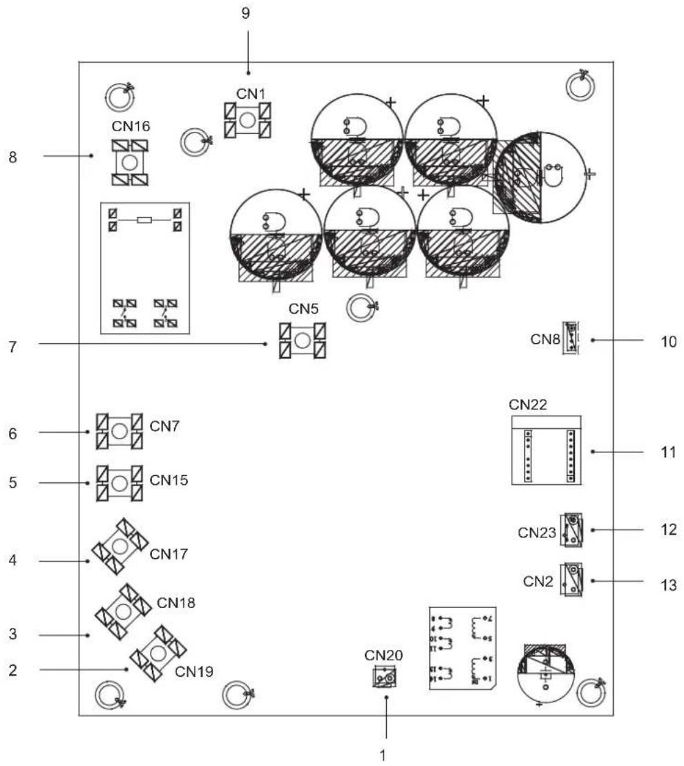
3) PCB C, filter board
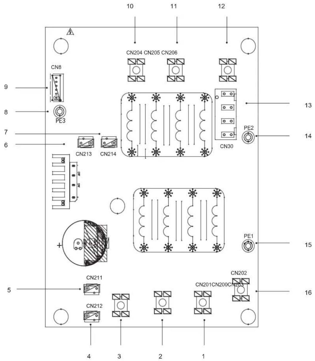
PCB C 3-phase 12/14/16kW
| Code Code | Assembly unit Assembly unit | ||
| 1 | Power supply L2(CN201) | 9 | Port for communication with PCB B (CN8) |
| 2 | Power supply L3(CN200) | 10 | Power filtering L3(L3') |
| 3 | Power supply N(CN203) | 11 | Power filtering L2(L2') |
| 4 | Power supply port of 310VDC(CN212) | 12 | Power filtering L1(L1') |
| 5 | Reserved(CN211) | 13 | Power supply port for main control board(CN30) |
| 6 | Port for FAN Reactor(CN213) | 14 | Port for ground wire(PE2) |
| 7 | Power supply port for Inverter module(CN214) | 15 | Port for ground wire(PE1) |
| 8 | Ground wire(PE3) | 16 | Power supply L1(L1) |
10 TEST RUNNING
Operate according to "key points for test running" on the electric control box cover.
CAUTION
- Test running can not start until the outdoor unit has been connected to the power for 12 hours.
- Test running can not start until all the valves are affirmed open.
- Never make the forced running .(Or the protector sits back, danger will occur.)
11 PRECAUTIONS ON REFRIGERANT LEAKAGE
When the refrigerant charge in appliance is more than 1.842kg, following requirements should be complied with.
- Requirements for charge limits in unventilated areas:
The maximum refrigerant charge in appliance shall be in accordance with the following:
$$ m _ {\max} = 2. 5 \times (\mathrm{LFL}) ^ {5 / 4} \times 1. 8 \times (\mathrm{A}) ^ {1 / 2} $$
or the required minimum floor area Amin to install an appliance with refrigerant charge m. shall be in accordance with following:
$$ A _ {\min} = \left(m _ {c} / (2. 5 \times (\mathrm{LFL}) ^ {5 / 4} \times 1. 8)\right) ^ {2} $$
where
m_max is the allowable maximum charge in a room, in kg
A is the room area, in m
A_min is the required minimum room area, in m ^2
m_e is the refrigerant charge in appliance, in kg
LFL is the lower flammable limit in kg/m, the value is 0.306 for R32 refrigerant
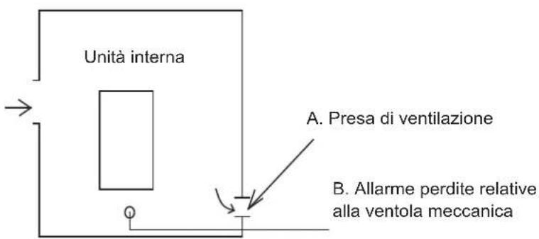
• Install mechanical ventilator to reduce the refrigerant thickness, under critical level. (ventilate regularly).
• Install leak alarm facility related to mechanical ventilator if you can not regularly ventilate.
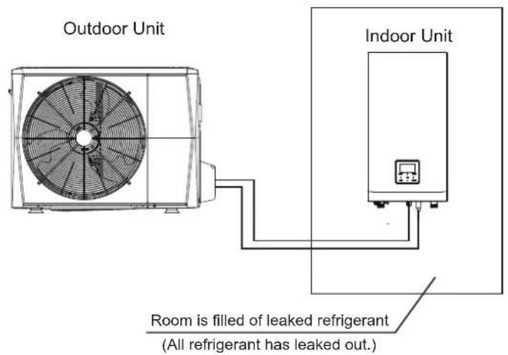
4/6 kW Fig.11-1
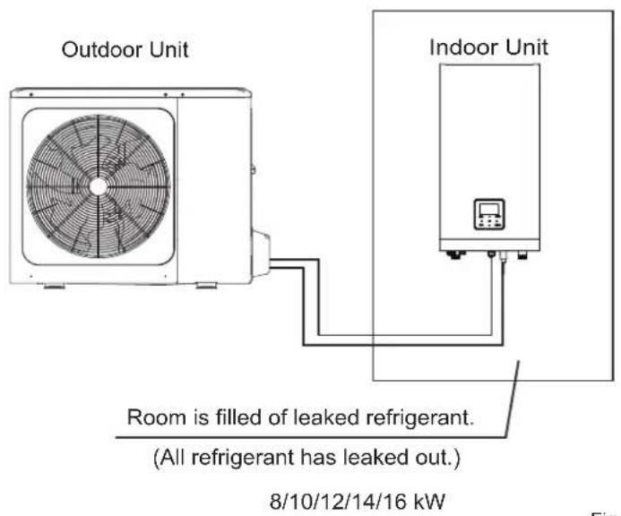
Fig.11-2
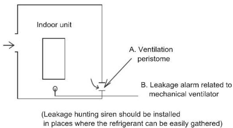
Fig.11-3
12 TURN OVER TO CUSTOMER
The owner's manual of indoor unit and owner's manual of outdoor unit must be turned over to the customer. Explain the contents in the owner's manual to the customers in details.

WARNING
- Ask your dealer for installation of the heat pump. Incomplete installation performed by yourself may result in a water leakage, electric shock, and fire.
- Ask your dealer for improvement, repair, and maintenance. Incomplete improvement, repair, and maintenance may result in a water leakage, electric shock, and fire.
- In order to avoid electric shock, fire or injury, or if you detect any abnormality such as smell of fire, turn off the power supply and call your dealer for instructions.
- Never let the indoor unit or the remote controller get wet. It may cause an electric shock or a fire.
- Never press the button of the remote controller with a hard, pointed object. The remote controller may be damaged.
- Never replace a fuse with that of wrong rated current or other wires when a fuse blows out. Use of wire or copper wire may cause the unit to break down or cause a fire.
- It is not good for your health to expose your body to the air flow for a long time.
- Do not insert fingers, rods or other objects into the air inlet or outlet. When the fan is rotating at high speed, it will cause injury.
- Never use a flammable spray such as hair spray, lacqueror paint near the unit. It may cause a fire.
- Never put any objects into the air inlet or outlet. Objects touching the fan at high speed can be dangerous.
- Do not dispose this product as unsorted municipal waste. Collection of such waste separately for special treatment is necessary. Do not dispose of electrical appliances as unsorted municipal waste, use separate collection facilities. Contact you local government for information regarding the connection systems available.
- If electrical appliances are disposed of in landfills or dumps, hazardous substances can leak into the groundwater and get into the food chain, damaging your health and well-being.
- To prevent refrigerant leak, contact your dealer. When the system is installed and runs in a small room, it is required to keep the concentration of the refrigerant, if by any chance coming out, below the limit. Otherwise, oxygen in the room may be affected, resulting in a serious accident.
- The refrigerant in the heat pump is safe and normally does not leak. If the refrigerant leaks in the room, contact with a fire of a burner, a heater or a cooker may result in a harmful gas.
- Turn off any combustible heating devices, ventilate the room, and contact the dealer where you purchased the unit. Do not use the heat pump until a service person confirms that the portion where the refrigerant leaks is repaired.

CAUTION
- Do not use the heat pump for other purposes. In order to avoid any quality deterioration, do not use the unit for cooling precision instruments, food, plants, animals or works of art.
- Before cleaning, be sure to stop the operation, turn the breaker off or pull out the supply cord. Otherwise, an electric shock and injury may result.
- In order to avoid electric shock or fire, make sure that an earth leak detector is installed.
- Be sure the heat pump is grounded. In order to avoid electric shock, make sure that the unit is grounded and that the earth wire is not connected to gas or water pipe, lightning conductor or telephone earth wire.
- In order to avoid injury, do not remove the fan guard of the outdoor unit.
- Do not operate the heat pump with a wet hand. An electric shock may happen.
- Do not touch the heat exchanger fins. These fins are sharp and could result in cutting injuries.
- Do not place items which might be damaged by moisture under the indoor unit. Condensation may form if the humidity is above 80%, the drain outlet is blocked or the filter is polluted.
- After a long use, check the unit stand and fitting for damage. If damaged, the unit may fall and result in injury.
- To avoid oxygen deficiency, ventilate the room sufficiently if equipment with burner is used together with the heat pump.
- Arrange the drain hose to ensure smooth drainage. Incomplete drainage may cause wetting of the building, furniture etc.
- Never touch the internal parts of the controller. Do not remove the front panel. Some parts inside are dangerous to touch, and a machine trouble may happen.
-
Never do the maintenances work by yourself. Please contact your local dealer to do the maintenances work.
-
Never expose little children, plants or animals directly to the air flow.
Adverse influence to little children, animals and plants may result. - Do not allow a child to mount on the outdoor unit or avoid placing any object on it.
Falling or tumbling may result in injury. - Do not operate the heat pump when using a room fumigation - type insecticide.
Failure to observe could cause the chemicals to become deposited in the unit, which could endanger the health of those who are hypersensitive to chemicals. - Do not place appliances which produce open fire in places exposed to the air flow from the unit or under the indoor unit.
It may cause incomplete combustion or deformation of the unit due to the heat. - Do not install the heat pump at any place where flammable gas may leak out.
If the gas leaks out and stays around the heat pump, a fire may break out. - The appliance is not intended for use by young children or infirm persons without supervision.
- Young children should be supervised to ensure that they do not play with the appliance.
- The outdoor unit window-shades should be periodic cleaning in case of being jammed.
This window-shapes is heat dissipation outlet of components, if being jammed will cause the components shorten their service life spans because of overheated for a long time. - The temperature of refrigerant circuit will be high, please keep the interconnection cable away from the copper tube.
13.1 Protection Equipment
This Protection Equipment will enable the Heat Pump to stop when the Heat Pump is to be directed running compulsively.
The protection equipment may be activated in following conditions:
■ Cooling Operation
- The air inlet or air outlet of outdoor unit is blocked.
- Strong wind is Continuously blowing to the air outlet of the outdoor unit.
■ Heating Operation
- Too much rubbish adhere to the filter in the water system
- The air outlet of indoor unit is choked
- Mishandling in operation:
If mishandling happens because of lighting or mobile wireless, please shut off the manual power switch, and turn on again, then push the ON/OFF button.

NOTE
When the protection equipment starts, please shut down the manual power switch, and restart operation after problem is solved.
13.2 About power cut
■ If power is cut during operation, stop all the operation immediately
■ Power comes again. If the auto-restart function is set on, then the unit will auto-restart.
13.3 Heating capacity
The heating operation is a heat-pump process that heat will be absorbed from outdoor air and released to indoor water. Once the outdoor temperature is decreased, heating capacity decreased correspondingly.
■ Other heating equipment is suggested to be used together when outdoor temperature is too low.
In some extreme cold upland that buy the indoor unit equipped with electrical heater will obtain better performance.(Refer to indoor unit owner's manual for details)

NOTE
- The motor in outdoor Unit will continue running for 60 seconds for to remove residual heat when the outdoor Unit receiving OFF command during heating operation.
- If the heat pump malfunction occurs because of disturb, please reconnect the heat pump to power, then turn on it again.
13.4 Compressor protection feature
■ A protection feature prevents the heat pump from being activated for approximately several minutes when it restarts immediately after operation.
13.5 Cooling and heating operation
■ The the indoor unit in the same system can not run cooling and heating at the same time.
If the Heat Pump Administrator has set running mode, then the heat pump can not run on modes other than the presetted. Standby or No Priority will be displayed in the Control Panel.
13.6 Features of heating operation
Water will not become hot immediately at the beginning of the heating operation, 3\~5 minutes ago (depends on the indoor and outdoor temperature), until the indoor heat exchanger become hot, then becomes hot.
■ During operation, the fan motor in the outdoor unit may stop running under high temperature.
13.7 Defrost in the heating operation
During heating operation, outdoor unit sometimes will frost. To increase efficiency, the unit will start defrosting automatically (about 2\~10 minutes), and then water will be drained out from outdoor unit.
■ During defrosting, the fan motors in the outdoor unit will stop running.
13.8 Error codes
When a safety device is activated, an error code will be displayed on the user interface.
A list of all errors and corrective actions can be found in the table below.
Reset the safety by turning the unit OFF and back ON.
In case this procedure for resetting the safety is not successful, contact your local dealer.
| ERROR CODE | MALFUNCTION OR PROTECTION | FAILURE CAUSE AND CORRECTIVE ACTION |
| E1 | Phase loss or neutral wire and live wire are connected reversely(only for three phase unit) | 1. Check whether the power supply cables are firmly conneted, avoid phase loss.2. Check whether the sequence of neutral wire and live wire are connected reversely. |
| E5 | The condenser outlet refrigerant temperature sensor (T3)error. | 1. The T3 sensor connector is loosen. Reconnect it.2. The T3 sensor connector is wet or there is water in. remove the water, make the connector dry. Add waterproof adhesive3. The T3 sensor failure, change a new sensor. |
| E6 | The ambient temperature sensor (T4) error. | 1. The T4 sensor connector is loosen. Reconnect it.2. The T4 sensor connector is wet or there is water in. remove the water, make the connector dry. Add waterproof adhesive3. The T4 sensor failure, change a new sensor. |
| E9 | Suction temperature sensor(Th) error | 1. The Th sensor connector is loosen. Reconnect it.2. The Th sensor connector is wet or there is water in. remove the water, make the connector dry. Add waterproof adhesive3. The Th sensor failure, change a new sensor. |
| ER | Discharge temperature sensor(Tp) error | 1. The Tp sensor connector is loosen. Reconnect it.2. The Tp sensor connector is wet or there is water in. remove the water, make the connector dry. Add waterproof adhesive3. The Tp sensor failure, change a new sensor. |
| HO | Communication fault between indoor unit and outdoor unit | 1. Wire doesn't connect between main control board PCB B and main control board of indoor unit. connect the wire.2. Whether there is a high magnetic field or high power interfere, such as lifts, large power transformers, etc.. To add a barrier to protect the unit or to move the unit to the other place. |
| HI | Communication error between inverter module PCB A and main control board PCB B | 1. Whether there is power connected to the PCB and driven board. Check the inverter module PCB indicator light is on or off. If Light is off, reconnect the power supply wire.2. If light is on, check the wire connection between inverter module PCB and main control board PCB, if the wire loosen or broken, reconnect the wire or change a new wire.3. Replace a new main PCB and driven board in turn. |
| HY | Three times (L0/L1) protect | The sum of the number of times L0 and L1 appear in an hour equals three. See L0 and L1 for fault handling methods |
| H6 | The DC fan failure | 1. Strong wind or typhoon below toward to the fan, to make the fan running in the opposite direction. Change the unit direction or make shelter to avoid typhoon below to the fan.2. Fan motor is broken, change a new fan motor. |
| H7 | Voltage protection | 1. Whether the power supply input is in the available range.2. Power off and power on for several times rapidly in short time.Remain the unit power off for more than 3 minutes than power on.3. The circuit defect part of Main control board is defective.Replace a new Main PCB. |
| H8 | Pressure sensor failure | 1. Pressure sensor connector is loosen, reconnect it.2. Pressure sensor failure. change a new sensor. |
| HF | Inverter module board EE prom failure | 1. The EEprom parameter is error, rewrite the EEprom data.2. EEprom chip part is broken, change a new EEprom chip part.3. Inverter module board is broken, change a new PCB. |
| HH | H6 displayed 10 times in 2 hours | Refer to H6 |
| HP | Low pressure protection in cooling Pe<0.6 occurred 3 times in an hour | Refer to P0 |
| P0 | Low pressure switch protection | 1. System is lack of refrigerant volume. Charge the refrigerant in right volume.2.When at heating mode or DHW mode, the outdoor heating exchanger is dirty or something is block on the surface. Clean the outdoor heating exchanger or remove the obstruction.3. The water flow is too low in cooling mode.increase the water flow.4. Electrical expansion valve locked or winding connector is loosen. Tap-tap the valve body and plug in/ plug off the connector for several times to make sure the valve is working correctly. |
| P1 | High pressure switch protection | Heating mode, DHW mode:1. The water flow is low; water temp is high, whether there is air in the water system. Release the air.2. Water pressure is lower than 0.1Mpa, charge the water to let the pressure in the range of 0.15~0.2Mpa.3. Over charge the refrigerant volume. Recharge the refrigerant in right volume.4. Electrical expansion valve locked or winding connector is loosen. Tap-tap the valve body and plug in/ plug off the connector for several times to make sure the valve is working correctly. And install the winding in the right location DHW mode: Water tank heat exchanger is smaller .Cooling mode:1.Heat exchanger cover is not removed. Remove it.2. Heat exchanger is dirty or something is block on the surface.Clean the heat exchanger or remove the obstruction. |
| P3 | Compressor overcurrent protection. | 1.The same reason to P1.2. Power supply voltage of the unit is low, increase the power voltage to the required range. |
| P4 | High discharge temperature protection. | 1.The same reason to P1.2.TW_out temp.sensor is loosen Reconnect it..3. T1 temp.sensor is loosen. Reconnect it.4. T5 temp.sensor is loosen. Reconnect it. |
| Pd | High temperature protection of refrigerant outlet temp of condenser. | 1. Heat exchanger cover is not removed. Remove it.2. Heat exchanger is dirty or something is block on the surface.Clean the heat exchanger or remove the obstruction.3. There is no enough space around the unit for heat exchanging.4. Fan motor is broken, replace a new one. |
| C7 | Transducer module temperature too high protection | 1. Power supply voltage of the unit is low, increase the power voltage to the required range.2. The space between the units is too narrow for heat exchange. Increase the space between the units.3. Heat exchanger is dirty or something is block on the surface.Clean the heat exchanger or remove the obstruction.4. Fan is not running. Fan motor or fan is broken, Change a new fan or fan motor.5. Water flow rate is low, there is air in system, or pump head is not enough. Release the air and reselect the pump.6. Water outlet temp.sensor is loosen or broken, reconnect it or change a new one. |
| F1 | Low DC generatrix voltage protection | 1. Check the power supply.2. If the power supply is OK, and check if LED light is OK, check the voltage PN, if it is 380V, the problem usually comes from the main board. And if the light is OFF, disconnect the power, check the IGBT, check those dioxides, if the voltage is not correct, the inverter board is damaged, change it.3. And if those IGBT are OK, which means the inverter board is OK, power form rectifier bridge is not correct, check the bridge. (Same method as IGBT, disconnect the power, check those dioxides are damaged or not).4. Usually if F1 exist when compressor start, the possible reason is main board. If F1 exist when fan start, it may be because of inverter board. |
| bH | PED PCB failure | 1. After 5 minutes of power-off interval, power on again and observe whether it can be recovered;2. If it can't be restored, replace PED safety plate, power on again, and observe whether it can be restored;3. If it can not be recovered, the IPM module board should be replaced. |
| P6 | ERROR CODE | MALFUNCTION OR PROTECTION | FAILURE CAUSE AND CORRECTIVE ACTION |
| L0 | Module protection | ||
| L1 | DC generatrix low voltage protection | ||
| L2 | DC generatrix high voltage protection | ||
| L4 | MCE malfunction | 1. Check the Heat pump system pressure;2. Check the phase resistance of compressor;3. Check the U、V、W power line connection sequence between the inverter board and the compressor;4. Check the L1、L2、L3 power line connection between the inverter board and the Filter board;5. Check the inverter board. | |
| L5 | Zero speed protection | ||
| L8 | Speed difference >15Hz protection between the front and the back clock | ||
| L9 | Speed difference >15Hz protection between the real and the setting speed |
14 TECHNICAL SPECIFICATIONS
| Model | 4kW 6kW 10kW8kW | |||
| Power supply | 220-240V~50Hz | |||
| Rated power input | 2200W | 2600W | 3300W | 3600W |
| Rated current 10.5A 14.5A | 12.0A | 16.0A | ||
| Nominal capacity | Refer to the technical data | |||
| Dimensions (W×H×D)[mm] | 1008*712*426 1118*865*523 | |||
| Packing (W×H×D)[mm] | 1065*810*485 | 1190*970*560 | ||
| Fan motor | DC motor / Horizontal | |||
| Compressor | DC inverter dual rotary | |||
| Heat exchanger | Fin-coil | |||
| Refrigerant | ||||
| Type | R32 | |||
| Quantity | 1500g | 1650g | ||
| Weight | ||||
| Net weight | 58kg | 75kg | ||
| Gross weight | 63.5kg | 89kg | ||
| Connections | ||||
| Liquid side | φ6.35 | φ9.52 | ||
| Gas side | φ15.9 | φ15.9 | ||
| Drain connection | DN32 | |||
| Max. piping length | 30m | |||
| Max. difference in height | 20m | |||
| Refrigerant to be added | 20g/m | 38g/m | ||
| Operation ambient temperature range | ||||
| Heating mode | -25~+35°C | |||
| Cooling mode | -5~+43°C | |||
| Domestic hot water mode | -25~+43°C | |||
| Model | 12kW 14kW | 16kW | 12kW 3-phase | 14kW 3-phase | 16kW 3-phase | |
| Power supply | 220-240V~50Hz | 380-415V 3N~50Hz | ||||
| Rated power input | 5400W 5400W 5700W | 6100W | 5700W | 6100W | ||
| Rated current | 24.5A | 25.0A | 26.0A | 9.0A | 10.0A | 11.0A |
| Nominal capacity | Refer to the technical data | |||||
| Dimensions (W×H×D)[mm] | 1118*865*523 1118*865*523 | |||||
| Packing (W×H×D)[mm] | 1190*970*560 | 1190*970*560 | ||||
| Fan motor | DC motor / Horizontal | |||||
| Compressor | DC inverter dual rotary | |||||
| Heat exchanger | Fin-coil | |||||
| Refrigerant | ||||||
| Type | R32 | |||||
| Quantity | 1840g | 1840g | ||||
| Weight | ||||||
| Net weight | 97kg | 112kg | ||||
| Gross weight | 110.5kg | 125.5kg | ||||
| Connections | ||||||
| Liquid side | φ9.52 | φ9.52 | ||||
| Gas side | φ15.9 | φ15.9 | ||||
| Drain connection | DN32 | |||||
| Max. piping length | 30m | |||||
| Max. difference in height | 20m | |||||
| Refrigerant to be added | 38g/m | |||||
| Operation ambient temperature range | ||||||
| Heating mode | -25~+35°C | |||||
| Cooling mode | -5~+43°C | |||||
| Domestic hot water mode | -25~+43°C | |||||
15 INFORMATION SERVICING
1) Checks to the area
Prior to beginning work on systems containing flammable refrigerants, safety checks are necessary to ensure that the risk of ignition is minimised. For repair to the refrigerating system, the following precautions shall be complied with prior to conducting work on the system.
2) Work procedure
Works shall be undertaken under a controlled procedure so as to minimise the risk of a flammable gas or vapour being present while the work is being performed.
3) General work area
All maintenance staff and others working in the local area shall be instructed on the nature of work being carried out. work in confined sapces shall be avoided. The area around the work space shall be sectioned off. Ensure that the conditions within the area have been made safe by control of flammable material.
4) Checking for presence of refrigerant
The area shall be checked with an appropriate refrigerant detector prior to and during work, to ensure the technician is aware of potentially flammable atmospheres. Ensure that the leak detection equipment being used is suitable for use with flammable refrigerants, i.e. no sparking, adequately sealed or intrinsically safe.
5) Presence of fire extinguisher
If any hot work is to be conducted on the refrigeration equipment or any associated parts, appropriate fire extinguishing equipment shall be available to hand. Have a dry power or CO_2 fire extinguisher adjacent to the charging area.
6) No ignition sources
No person carrying out work in relation to a refrigeration system which involves exposing any pipe work that contains or has contained flammable refrigerant shall use any sources of ignition in such a manner that it may lead to the risk of fire or explosion. All possible ignition sources, including cigarette smoking, should be kept sufficiently far away from the site of installation, repairing, removing and disposal, during which flammable refrigerant can possibly be released to the surrounding space. Prior to work taking place, the area around the equipment is to be surveyed to make sure that there are no flammable hazards or ignition risks. NO SMOKING signs shall be displayed.
7) Ventilated area
Ensure that the area is in the open or that it is adequately ventilated before breaking into the system or conducting any hot work. A degree of ventilation shall continue during the period that the work is carried out. The ventilation should safely disperse any released refrigerant and preferably expel it externally into the atmosphere.
8) Checks to the refrigeration equipment
Where electrical components are being changed, they shall be fit for the purpose and to the correct specification. At all times the manufacturer's maintenance and service guidelines shall be followed. If in doubt consult the manufacturer's technical department for assistance. The following checks shall be applied to installations using flammable refrigerants:
• The charge size is in accordance with the room size within which the refrigerant containing parts are installed;
• The ventilation machinery and outlets are operating adequately and are not obstructed;
- If an indirect refrigerating circuit is being used, the secondary circuits shall be checked for the presence of refrigerant; marking to the equipment continues to be visible and legible.
- Marking and signs that are illegible shall be corrected;
- Refrigeration pipe or components are installed in a position where they are unlikely to be exposed to any substance which may corrode refrigerant containing components, unless the components are constructed of materials which are inherently resistant to being corroded or are suitably protected against being so corroded.
9) Checks to electrical devices
Repair and maintenance to electrical components shall include initial safety checks and component inspection procedures. If a fault exists that could compromise safety, then no electrical supply shall be connected to the circuit until it is satisfactorily dealt with. If the fault cannot be corrected immediately but it is necessary to continue operation, and adequate temporary solution shall be used. This shall be reported to the owner of the equipment so all parties are advised.
Initial safety checks shall include:
- That capacitors are discharged: this shall be done in a safe manner to avoid possibility of sparking;
- That there no live electrical components and wiring are exposed while charging, recovering or purging the system;
• That there is continuity of earth bonding.
10) Repairs to sealed components
a) During repairs to sealed components, all electrical supplies shall be disconnected from the equipment being worked upon prior to any removal of sealed covers, etc. If it is absolutely necessary to have an electrical supply to equipment during servicing, then a permanently operating form of leak detection shall be located at the most critical point to warn of a potentially hazardous situation.
b) Particular attention shall be paid to the following to ensure that by working on electrical components, the casing is not altered in such a way that the level of protection is affected. This shall include damage to cables, excessive number of connections, terminals not made to original specification, damage to seals, incorrect fitting of glands, etc.
- Ensure that apparatus is mounted securely.
- Ensure that seals or sealing materials have not degraded such that they no longer serve the purpose of preventing the ingress of flammable atmospheres. Replacement parts shall be in accordance with the manufacturer's specifications.
NOTE
The use of silicon sealant may inhibit the effectiveness of some types of leak detection equipment. Instrinsically safe components do not have to be isolated prior to working on them.
11) Repair to intrinsically safe components
Do not apply any permanent inductive or capacitance loads to the circuit without ensuring that this will not exceed the permissible voltage and current permitted for the equipment in use. Intrinsically safe components are the only types that can be worked on while live in the presence of a flammable atmosphere. The test apparatus shall be at the correct rating. Replace components only with parts specified by the manufacturer. Other parts may result in the ignition of refrigerant in the atmosphere from a leak.
12) Cabling
Check that cabling will not be subject to wear, corrosion, excessive pressure, vibration, sharp edges or any other adverse environmental effects. The check shall also take into account the effects of aging or continual vibration from sources such as compressors or fans.
13) Detection of flammable refrigerants
Under no circumstances shall potential sources of ignition be used in the searching for or detection of refrigerant leaks. A halide torch (or any other detector using a naked flame) shall not be used.
14) Leak detection methods
The following leak detection methods are deemed acceptable for systems containing flammable refrigerants. Electronic leak detectors shall be used to detect flammable refrigerants, but the sensitivity may not be adequate, or may need re-calibration.(Detection equipment shall be calibrated in a refrigerant-free area.) Ensure that the detector is not a potential source of ignition and is suitable for the refrigerant. Leak detection equipment shall be set at a percentage of the LFL of the refrigerant and shall be calibrated to the refrigerant employed and the appropriate percentage of gas (25% maximum) is confirmed. Leak detection fluids are suitable for use with most refrigerants but the use of detergents containing chlorine shall be avoided as the chlorine may react with the refrigerant and corrode the copper pipe-work. If a leak is suspected ,all naked flames shall be removed or extinguished. If a leakage of refrigerat is found which requires brazing, all of the refrigerant shall be recovered from the system, or isolated(by means of shut off valves) in a part of the system remote from the leak . Oxygen free nitrogen(OFN) shall then be purged through the system both before and during the brazing process.
15) Removal and evacuation
When breaking into the refrigerant circuit to make repairs of for any other purpose conventional procedures shall be used, However, it is important that best practice is followed since flammability is a consideration. The following procedure shall be adhered to:
- Remove refrigerant;
• Purge the circuit with inert gas; - Evacuate;
• Purge again with inert gas; - Open the circuit by cutting or brazing.
The refrigerant charge shall be recovered into the correct recovery cylinders. The system shall be flushed with OFN to render the unit safe. This process may need to be repeated several times.
Compressed air or oxygen shall not be used for this task.
Flushing shall be achieved by breaking the vacuum in the system with OFN and continuing to fill until the working pressure is achieved, then venting to atmosphere, and finally pulling down to a vacuum. This process shall be repeated until no refrigerant is within the system.
When the final OFN charge is used, the system shall be vented down to atmospheric pressure to enable work to take place. This operation is absolutely vital if brazing operations on the pipe-work are to take place.
Ensure that the outlet for the vacuum pump is not closed to any ignition sources and there is ventilation available.
16) Charging procedures
In addition to conventional charging procedures, the following requirements shall be followed:
- Ensure that contamination of different refrigerants does not occur when using charging equipment. Hoses or lines shall be as short as possible to minimize the amount of refrigerant contained in them.
• Cylinders shall be kept upright.
- Ensure that the refrigeration system is earthed prior to charging the system with refrigerant.
- Label the system when charging is complete(if not already).
• Extreme care shall be taken not to overfill the refrigeration system.
- Prior to recharging the system it shall be pressure tested with OFN. The system shall be leak tested on completion of charging but prior to commissioning. A follow up leak test shall be carried out prior to leaving the site.
17) Decommissioning
Before carrying out this procedure, it is essential that the technician is completely familiar with the equipment and all its detail. It is recommended good practice that all refrigerants are recovered safely. Prior to the task being carried out, an oil and refrigerant sample shall be taken.
In case analysis is required prior to re-use of reclaimed refrigerant. It is essential that electrical power is available before the task is commenced.
a) Become familiar with the equipment and its operation.
b) Isolate system electrically
c) Before attempting the procedure ensure that:
- Mechanical handling equipment is available, if required, for handling refrigerant cylinders;
- All personal protective equipment is available and being used correctly;
• The recovery process is supervised at all times by a competent person; - Recovery equipment and cylinders conform to the appropriate standards.
d) Pump down refrigerant system, if possible.
e) If a vacuum is not possible, make a manifold so that refrigerant can be removed from various parts of the system. f) Make sure that cylinder is situated on the scales before recovery takes place.
g) Start the recovery machine and operate in accordance with manufacturer's instructions.
h) Do not overfill cylinders. (No more than 80% volume liquid charge).
i) Do not exceed the maximum working pressure of the cylinder, even temporarily.
j) When the cylinders have been filled correctly and the process completed, make sure that the cylinders and the equipment are removed from site promptly and all isolation valves on the equipment are closed off.
k) Recovered refrigerant shall not be charged into another refrigeration system unless it has been cleaned and checked.
18) Labelling
Equipment shall be labelled stating that it has been de-commissioned and emptied of refrigerant. The label shall be dated and signed. Ensure that there are labels on the equipment stating the equipment contains flammable refrigerant.
19) Recovery
When removing refrigerant from a system, either for service or decommissioning, it is recommended good practice that all refrigerants are removed safely.
When tranferring refrigerant into cylinders, ensure that only appropriate refrigerant recovery cylinders are employed. Ensure that the correct numbers of cylinders for holding the total system charge are available. All cylinders to be used are designated for the recovered refrigerant and labelled for that refrigerant(i.e special cylinders for the recovery of refrigerant). Cylinders shall be complete with pressure relief valve and associated shut-off valves in good working order.
Empty recovery cylinders are evacuated and, if possible, cooled before recovery occurs.
The recovery equipment shall be in good working order with a set of instructions concerning the equipment that is at hand and shall be suitable for the recovery of flammable refrigerants. In addition, a set of calibrated weighing scales shall be available and in good working order.
Hoses shall be complete with leak-free disconnect couplings and in good condition. Before using the recovery machine, check that it is in satisfactory working order, has been properly maintained and that any associated electrical components are sealed to prevent ignition in the event of a refrigerant release. Consult manufacturer if in doubt.
The recovered refrigerant shall be returned to the refrigerant supplier in the correct recovery cylinder, and the relevant Waste Transfer Note arranged. Do not mix refrigerants in recovery units and especially not in cylinders.
If compressors or compressor oils are to be removed, ensure that they have been evacuated to an acceptable level to make certain that flammable refrigerant does not remain within the lubricant. The evacuation process shall be carried out prior to retruning the compressor to the suppliers. Only electric heating to the compressor body shall be employed to accelerate this process. When oil is drained from a system, it shall be carried out safely.
20) Transportation, marking and storage for units
Transport of equipment containing flammable refrigerants Compliance with the transport regulations
Marking of equipment using signs Compliance with local regulations
Disposal of equipment using flammable refrigerants Compliance with national regulations
Storage of equipment/appliances
The storage of equipment should be in accordance with the manufacturer's instructions.
Storage of packed (unsold) equipment
Storage package protection should be constructed such that mechanical damage to the equipment inside the package will not cause a leak of the refrigerant charge.
The maximum number of pieces of equipment permitted to be stored together will be determined by local regulations.
ANNEX A: Refrigerant cycle
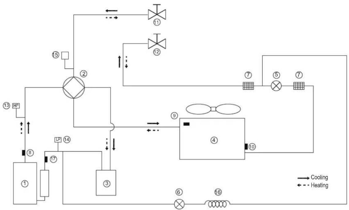
flowchart
graph TD
    A["①"] --> B["②"]
    B --> C["③"]
    C --> D["④"]
    D --> E["⑤"]
    E --> F["⑦"]
    F --> G["⑧"]
    G --> H["⑨"]
    H --> I["⑩"]
    I --> J["⑪"]
    J --> K["⑫"]
    K --> L["⑬"]
    L --> M["⑭"]
    M --> N["⑮"]
    N --> O["⑯"]
    O --> P["⑰"]
    P --> Q["⑱"]
    Q --> R["⑲"]
    R --> S["⑳"]
    S --> T["㉑"]
    T --> U["㉒"]
    U --> V["㉓"]
    V --> W["㉔"]
    W --> X["㉕"]
    X --> Y["㉖"]
    Y --> Z["㉗"]
    Z --> AA["㉘"]
    AA --> AB["㉙"]
    AB --> AC["㉚"]
    AC --> AD["㉛"]
    AD --> AE["㉜"]
    AE --> AF["㉝"]
    AF --> AG["㉟"]
    AG --> AH["㉟a"]
    AH --> AI["㉟b"]
    AI --> AJ["㉟c"]
    AJ --> AK["㉟d"]
    AK --> AL["㉟e"]
    AL --> AM["㉟f"]
    AM --> AN["㉟g"]
    AN --> AO["㉟h"]
    AO --> AP["㉟i"]
    AP --> AQ["㉟j"]
    AQ --> AR["㉟k"]
    AR --> AS["㉟l"]
    AS --> AT["㉟m"]
    AT --> AU["㉟n"]
    AU --> AV["㉟o"]
    AV --> AW["㉟p"]
    AW --> AX["㉟q"]
    AX --> AY["㉟r"]
    AY --> AZ["㉟t"]
    AZ --> BA["㉟u"]
    BA --> BB["㉟v"]
    BB --> BC["㉟w"]
    BC --> BD["㉟x"]
    BD --> BE["㉟y"]
    BE --> BF["㉟z"]
| Item | Description Description | Item | |
| 1 | Compressor | 10 | Evaporation sensor in heating(Condenser sensor in cooling) |
| 2 | 4-Way Valve | 11 | Stop valve (gas) |
| 3 | Gas-liquid separator | 12 | Stop valve (liquid) |
| 4 | Air side heat exchanger | 13 | High Pressure Switch |
| 5 | Electronic expansion Valve | 14 | Low Pressure Switch |
| 6 | Single-way electromagnetic valve | 15 | Pressure sensor |
| 7 | Strainer | 16 | Capillary |
| 8 | Discharge temperature sensor | 17 | Suction temperature sensor |
| 9 | Outdoor temperature sensor |
ANNEX B:
To install the E-heating tape at the drainage outlet (by client)
Connect the wireCeating tape at the drainage outlet to the wire joint XT3.
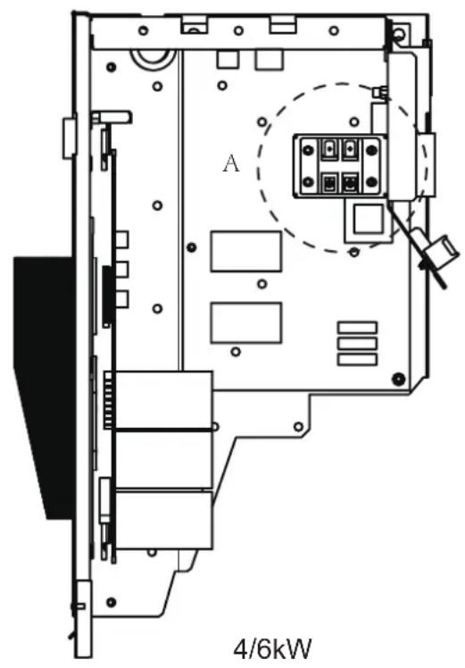
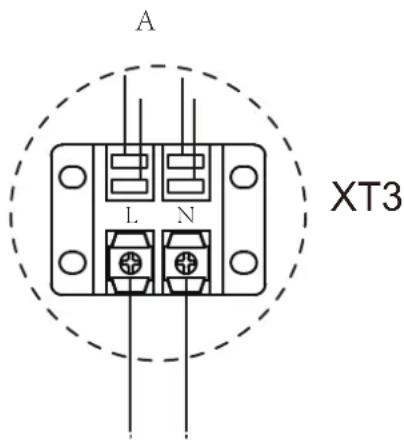
To the heating tape of drainage outlet
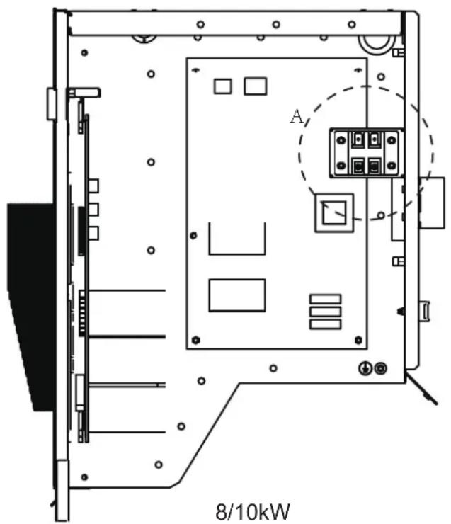

NOTE
The picture is for reference only, please refer to the actual product.
The power of the E-heating tape shall not exceed 40W/200mA, supply volatge 230VAC.
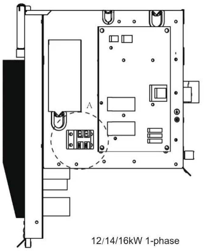
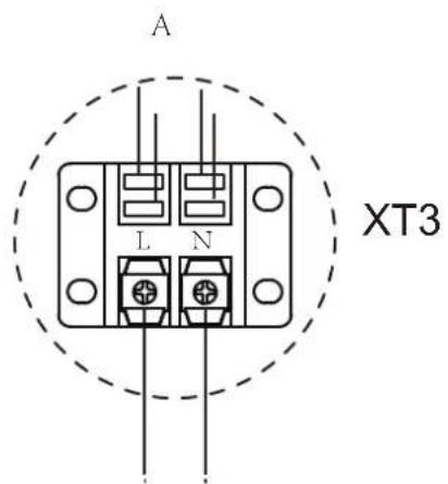
To the heating tape of drainage outlet
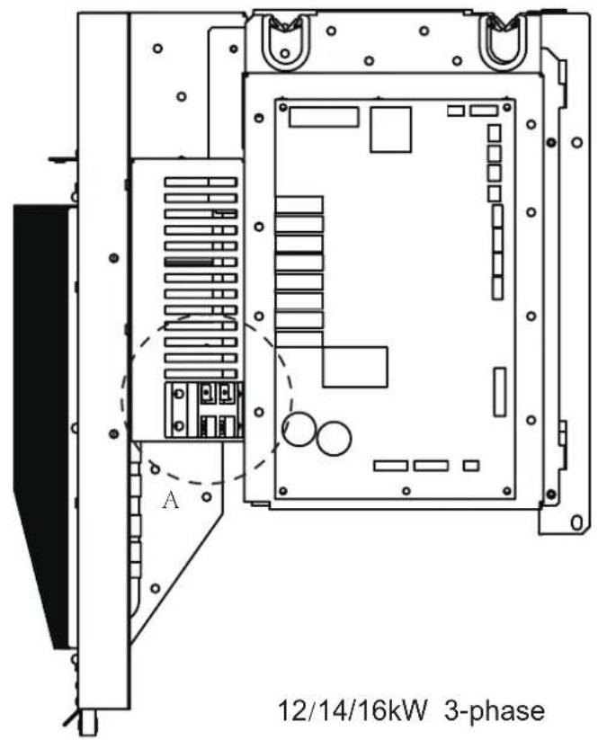

NOTE
The picture is for reference only, please refer to the actual product.
The power of the E-heating tape shall not exceed 40W/200mA, supply volatge 230VAC.
MANUEL D'INSTALLATION ET D'UTILISATION
natural_image
Technical line drawing of a fan or air conditioning unit with concentric circular patterns and radial blades (no text or symbols)REMARQUE IMPORTANTE :

12 REMISE AU CLIENT 26
13 FONCTIONNEMENT ET PERFORMANCE 28
natural_image
Technical line drawing of a fan with visible blades and central hub (no text or symbols)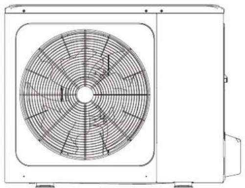
natural_image
Technical line drawing of a dual-panel air conditioner unit with fan blades and ventilation slots (no text or symbols)8/10 kW4/6 kW
natural_image
Warning symbol of a flame inside a triangle (no text or numbers)
natural_image
Simple diagram showing a gray rectangular object with an arrow indicating rotation and a cross mark (no text or symbols)
natural_image
Simple diagram showing a gray rectangular object with an arrow indicating rotation, no text or symbols present.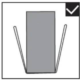
natural_image
Simple diagram of a gray rectangle with two vertical lines and a checkmark in the corner (no text or symbols)natural_image
Two workers carrying a large fan-shaped device with a central fan blade (no text or symbols visible)4/6/8/10/12/14/16 kW
(unité: mm)

REMARQUE
natural_image
Technical line drawing of a mechanical fan or vent assembly with no visible text or symbolsFig: 6-4
| Unité | A(mm) |
| 4~16kW | ≥2000 |
Fig: 6-6

REMARQUE
natural_image
Simple line drawing of a graduation cap with two cylinders and a checkmark (no text or symbols)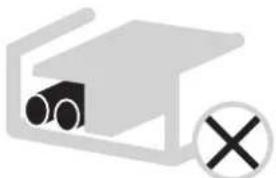
natural_image
Simple diagram of a device with pipes and a cross symbol (no text or labels)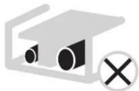
natural_image
Simple diagram of a graduation cap with two eyes and a cross symbol (no text or labels)natural_image
Technical line drawing of a multi-chamber air conditioning unit with fan and cooling unit (no text or symbols)
REMARQUE
natural_image
Technical line drawing of a dual-panel air conditioning unit with fan blades and central hub (no text or symbols)PCB C 3-phase 12/14/16kW
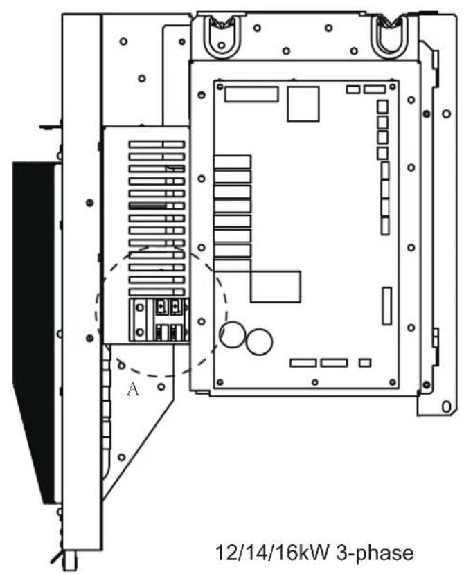
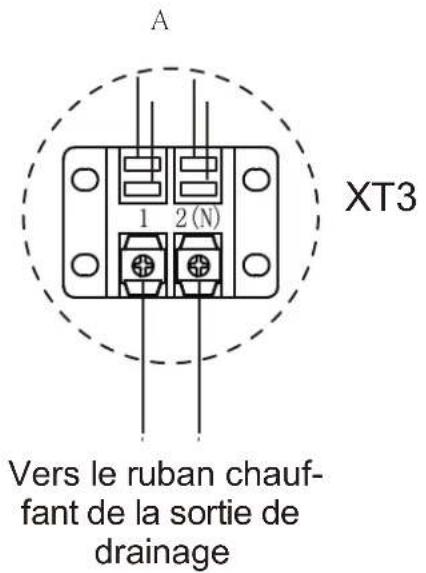
natural_image
Technical line drawing of a mechanical fan or air conditioning unit with concentric circular blades (no text or symbols)WICHTIGER HINWEIS:

natural_image
Technical line drawing of a fan with visible blades and central hub (no text or symbols)4/6 kW
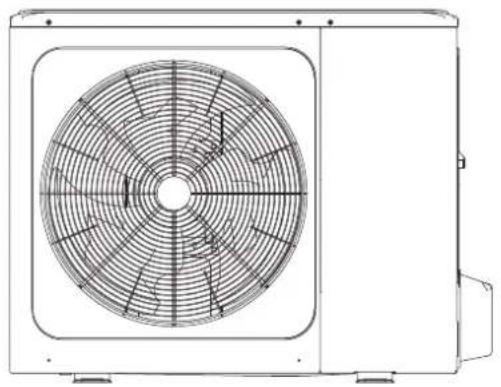
natural_image
Technical line drawing of a dual-panel air conditioner unit with fan blades and central hub (no text or symbols)8/10/12/14/16 kW
natural_image
Technical line drawing of a rectangular industrial enclosure with ventilation grilles and mounting feet (no text or symbols)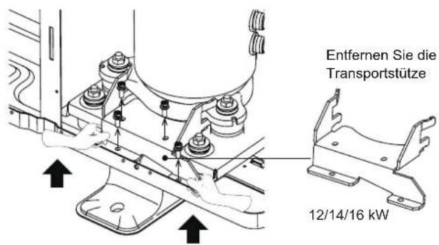
natural_image
Warning symbol of a flame inside a triangle (no text or numbers)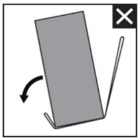
natural_image
Simple diagram showing a gray rectangular object with an arrow indicating rotation and a black X mark (no text or symbols)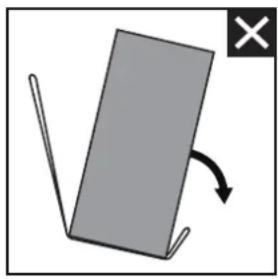
natural_image
Simple diagram showing a gray rectangular object with an arrow indicating rotation, no text or symbols present.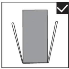
natural_image
Simple diagram of a gray rectangle with two vertical lines and a checkmark in the corner (no text or symbols)natural_image
Two workers carrying a large fan-shaped device with a central fan blade (no text or symbols visible)natural_image
Technical line drawing of a mechanical fan or vent assembly mounted on a base (no text or symbols)Abb: 6-4
Abb: 6-6
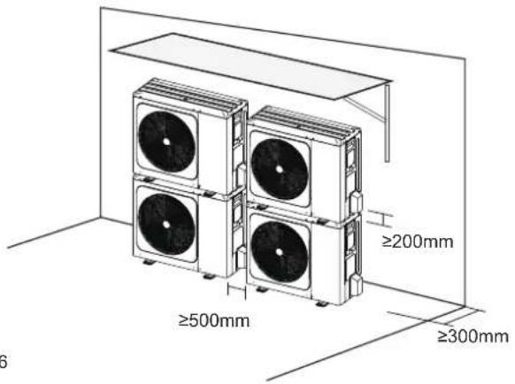
| Einheit | A(mm) |
| 4~16kW | ≥2000 |
HINWEIS
natural_image
Three identical diagrams showing a device with circular components and checkmark indicators, no text or symbols present.natural_image
Technical line drawing of a multi-chamber air conditioning unit with fan and cooling unit (no text or symbols)
HINWEIS
natural_image
Technical line drawing of a four-wheeler air fan with labeled component (no text or symbols beyond label)natural_image
Technical line drawing of a front-end air conditioning unit with fan blades and central hub (no text or symbols on the diagram itself)
HINWEIS
natural_image
Technical line drawing of a fan or air conditioning unit with concentric circular grid pattern (no text or symbols)NOTA IMPORTANTE:

natural_image
Technical line drawing of a front-mounted air fan with visible blades and mounting base (no text or symbols)4/6 kW
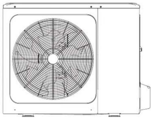
natural_image
Technical line drawing of a dual-panel air conditioner unit with fan blades and ventilation slots (no text or symbols)8/10/12/14/16 kW
natural_image
Technical line drawing of a rectangular industrial air conditioner unit with cooling fins and mounting base (no text or symbols)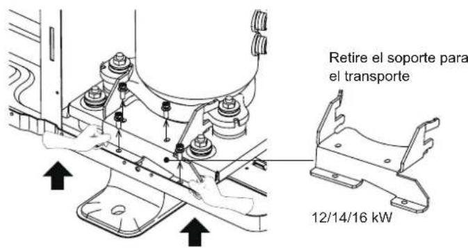
natural_image
Warning symbol of a flame inside a triangle (no text or numbers)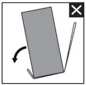
natural_image
Simple diagram showing a gray rectangular object with an arrow indicating rotation and a black X mark on the right (no text or symbols)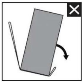
natural_image
Simple diagram showing a gray rectangular object with an arrow indicating rotation, no text or symbols present.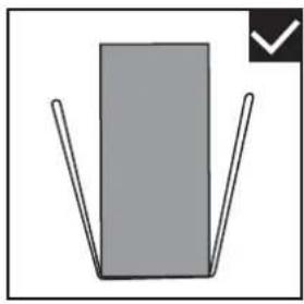
natural_image
Simple diagram of a gray rectangle with two vertical lines and a checkmark icon (no text or symbols)natural_image
Two workers carrying a large fan-shaped device with a central grille (no text or symbols visible)① Construya un dosel grande.
natural_image
Technical line drawing of a mechanical fan or vent assembly with no visible text or symbolsFig: 6-4
Fig: 6-6
NOTA
natural_image
Three identical diagrams showing a device with circular components and checkmark indicators, no text or symbols present.natural_image
Technical line drawing of a multi-chamber air conditioning unit with fan and cooling unit (no text or symbols)
NOTA
natural_image
Technical line drawing of a four-wheeler air fan with labeled component (no text or symbols beyond label)natural_image
Technical line drawing of a dual-panel air conditioning unit with fan blades and central hub (no text or symbols on the diagram itself)natural_image
Technical line drawing of a fan or vent assembly with concentric circular patterns (no text or symbols)BELANGRIJK:

natural_image
Technical line drawing of a fan with visible blades and central hub (no text or symbols)4/6 kW

natural_image
Technical line drawing of a dual-panel air conditioner unit with fan blades and ventilation slots (no text or symbols)8/10/12/14/16 kW
natural_image
Technical line drawing of a rectangular industrial enclosure with ventilation grilles and mounting feet (no text or symbols)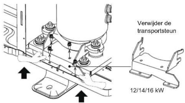
natural_image
Warning symbol of a flame inside a triangle (no text or numbers)Let op: brandgevaar/brandbare materialen
⚠ WAARSCHUWING

natural_image
Simple diagram showing a gray rectangular object with an arrow indicating rotation and a cross mark (no text or symbols)
natural_image
Simple diagram showing a gray rectangular object with an arrow indicating rotation, no text or symbols present.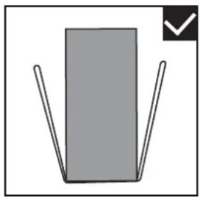
natural_image
Simple diagram of a gray rectangle with two vertical lines and a checkmark in the corner (no text or symbols)natural_image
Two workers carrying a large fan-shaped device with a central grille (no text or symbols visible)natural_image
Technical line drawing of a mechanical fan or vent assembly with no visible text or symbolsAfb: 6-4
| Eenheid | A(mm) |
| 4~16 kW | ≥2000 |
OPMERKING
natural_image
Three identical diagrams showing a device with circular components and checkmark indicators, no text or symbols present.MFA : Max. Zekering Amp. (A)
MSC : Max. Zekering Amp. (A)
natural_image
Technical line drawing of a multi-chamber air conditioning unit with fan and cooling unit (no text or symbols)
OPMERKING
natural_image
Technical line drawing of a four-wheeler air fan with labeled component (no text or symbols beyond label)natural_image
Technical line drawing of a front-end air conditioning unit with fan blades and central hub (no text or symbols on the diagram itself)natural_image
Technical line drawing of a front-mounted air conditioning fan with concentric blades (no text or symbols)WAŻNA INFORMACJA:

natural_image
Technical line drawing of a fan with visible blades and central hub (no text or symbols)4/6 kW
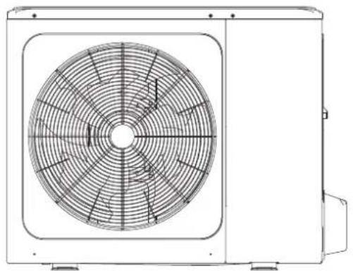
natural_image
Technical line drawing of a dual-panel air conditioner unit with fan blades and central hub (no text or symbols)8/10/12/14/16 kW
natural_image
Technical line drawing of a rectangular industrial enclosure with ventilation grilles and mounting feet (no text or symbols)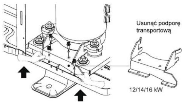
natural_image
Warning symbol of a flame inside a triangle (no text or numbers)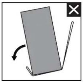
natural_image
Simple diagram showing a gray rectangular object with an arrow indicating rotation and a cross mark (no text or symbols)
natural_image
Simple diagram showing a gray rectangular object with an arrow indicating rotation, no text or symbols present.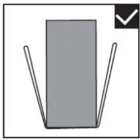
natural_image
Simple diagram of a gray rectangle with two vertical lines and a checkmark icon (no text or symbols)natural_image
Two workers carrying a large fan-shaped device with a central hub, depicted in line style (no text or symbols)natural_image
Technical line drawing of a mechanical fan or vent assembly with no visible text or symbolsRys.: 6-4
| Jednostka | A (mm) |
| 4~16 kW | ≥ 2000 |
INFORMACJA

UWAGA
natural_image
Three identical 3D icons showing a device with circular components and checkmark indicators, no text or symbols present.natural_image
Technical line drawing of a multi-chamber air conditioning unit with fan and cooling unit (no text or symbols)
INFORMACJA
natural_image
Technical line drawing of a four-wheeled fan or vent with labeled section 1 (no text or symbols on the fan itself)natural_image
Technical diagram of a dual-panel air conditioning unit with fan blades and central hub, labeled '8/10/12/14/16 kW' (no text or symbols on the diagram itself)natural_image
Technical line drawing of a fan or vent assembly with radial slots and concentric circles (no text or symbols)OBSAH
natural_image
Technical line drawing of a rectangular air conditioner unit with fan blades and mounting base (no text or symbols)4/6 kW
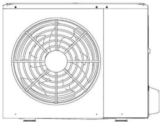
natural_image
Technical line drawing of a fan or vent assembly with radial blades and central hub (no text or symbols)8/10/12/14/16 kW
natural_image
Technical line drawing of a rectangular industrial air conditioner unit with cooling fins and mounting base (no text or symbols)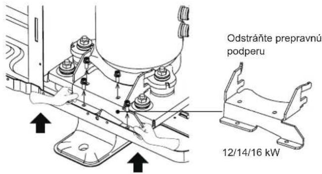
POZNÁMKA
natural_image
Warning symbol of a flame inside a triangle (no text or numbers)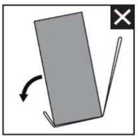
natural_image
Simple diagram showing a gray rectangular object with an arrow indicating rotation and a cross mark (no text or symbols)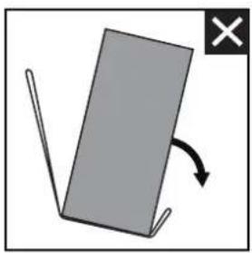
natural_image
Simple diagram showing a tilted rectangular object with an arrow indicating rotation, no text or symbols present.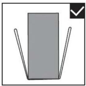
natural_image
Simple diagram of a gray rectangle with two vertical lines and a checkmark in the corner (no text or symbols)natural_image
Technical line drawing of a mechanical fan or vent assembly with no visible text or symbolsObr.: 6-4
Obr.: 6-6
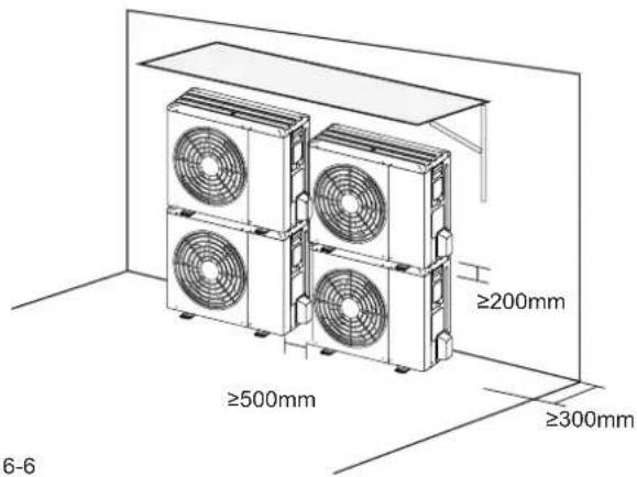
Jednotka A(mm)
4\~16kW ≥2000
POZNÁMKA
| Jednotka A(mm) B1(mm) B2(mm) C(mm) | |
| 4~16kW ≥3000 ≥2000 ≥150 ≥600 |
natural_image
Simple icon of a graduation cap with two eyes and a checkmark (no text or symbols)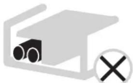
natural_image
Simple line drawing of a container with a cylindrical object inside and a cross symbol below (no text or labels)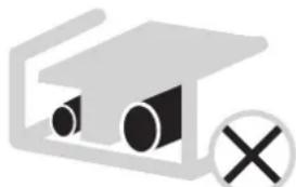
natural_image
Simple icon of a device with two circular components and a cross symbol (no text or labels)natural_image
Technical line drawing of a large air conditioning unit with fan and internal components (no text or symbols)POZNÁMKA
natural_image
Technical line drawing of a front-mounted air conditioner unit with fan blades (no text or symbols)natural_image
Technical line drawing of a fan or vent assembly with no visible text or symbolsnatural_image
Technical line drawing of a fan or air conditioning unit with concentric circular patterns (no text or symbols)FONTOS MEGJEGYZÉS:

natural_image
Technical line drawing of a fan with visible blades and central hub (no text or symbols)4/6 kW

natural_image
Technical line drawing of a dual-panel air conditioner unit with fan blades and central hub (no text or symbols)8/10/12/14/16 kW
natural_image
Technical line drawing of a rectangular industrial air conditioner unit with cooling fins and mounting base (no text or symbols)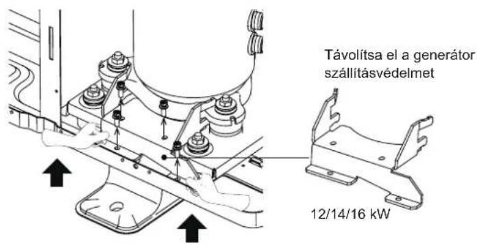
natural_image
Warning symbol of a flame inside a triangle (no text or numbers)
natural_image
Simple diagram showing a gray rectangular object with an arrow indicating rotation and a cross mark (no text or symbols)
natural_image
Simple diagram showing a gray rectangular object with an arrow indicating rotation, no text or symbols present.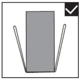
natural_image
Simple diagram of a gray rectangle with two vertical lines and a checkmark in the corner (no text or symbols)natural_image
Two workers carrying a large fan-shaped machine with a central fan blade (no text or symbols visible)natural_image
Technical line drawing of a mechanical fan or vent assembly with no visible text or symbols6-4. ábra
natural_image
Three identical diagrams showing a device with circular components and checkmark indicators, no text or symbols present.natural_image
Technical line drawing of a multi-chamber air conditioning unit with fan and cooling unit (no text or symbols)