
FMS01 - Wall mount SANUS - Free user manual and instructions
Find the device manual for free FMS01 SANUS in PDF.
User questions about FMS01 SANUS
0 question about this device. Answer the ones you know or ask your own.
Ask a new question about this device
Download the instructions for your Wall mount in PDF format for free! Find your manual FMS01 - SANUS and take your electronic device back in hand. On this page are published all the documents necessary for the use of your device. FMS01 by SANUS.
USER MANUAL FMS01 SANUS
natural_image
Technical illustration of a mechanical lifting device with mounting brackets and structural supports (no text or symbols)We are here to help!
Please contact Customer Service with any questions.
Customer Service
Americas: 800-359-5520 • 651-484-7988 • info@sanus.com
Europe, Middle East, and Africa: +31 (0) 495 580 852 • europe.sanus@milestone.com
Asia Pacifi c: 86 755 8996 9226 • sanus.ap@milestone.com
SANUS • 6436 City West Parkway • Eden Prairie, MN 55344 USA
©2012 Milestone AV Technologies, a Duchossois Group Company. All rights reserved. Sanus is a division of Milestone. All other brand names or marks are used for identification purposes and are trademarks of their respective owners.
English - How to use this manual
For best results, reference both the text and illustrations.
OR Select one item or the other.
OPT This item is optional
English Text Pages 3-20
IMPORTANT SAFETY INSTRUCTIONS – SAVE THESE INSTRUCTIONS – PLEASE READ ENTIRE MANUAL PRIOR TO USE
WARNING: Avoid potential personal injuries and property damage!
- Do not exceed the maximum weight capacity of 59 kg (130 lb). This includes TV and accessories.
- Use this mounting system only for its intended use as described in these instructions. Do not use attachments not recommended by the manufacturer.
- The wall must be capable of supporting five times the weight of the TV and mount combined.
- This product is not designed for use in metal stud walls!
- This product is for household use only.
- Do not use this product for any purpose not explicitly specified by manufacturer.
- If you do not understand these instructions, or have doubts about the safety of the installation, assembly or use of this product, contact Customer Service or call a qualified contractor.
- Manufacturer is not responsible for damage or injury caused by incorrect assembly or use.
Specifications
Thank you for purchasing the FMS01. This product is only intended for use with Furniture Mount System (FMS) compatible furniture. Look for the following icon:

Swivel2° (only applicable if the TV is mounted to the pillar)
Tilt2°
T V MOUNTED TO PILLAR
STEPS 1-7

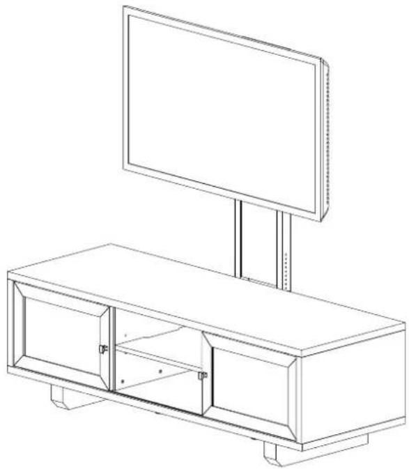
natural_image
Line drawing of a modern modular TV unit with a monitor and stand (no text or symbols)T V MOUNTED TO WALL
STEPS 1 AND 8-10
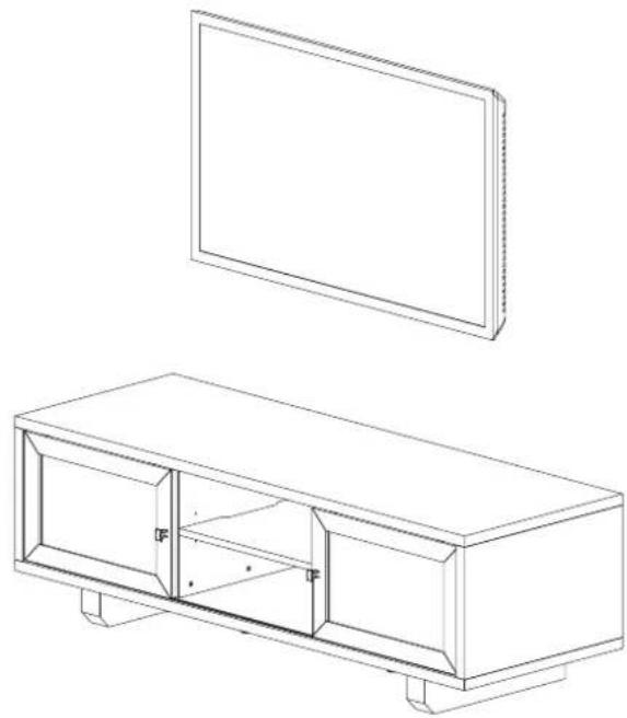
natural_image
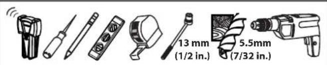
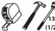
Line drawing of a rectangular TV set with two panels, one above showing a flat panel and the other below showing internal compartments (no text or symbols)Required Tools
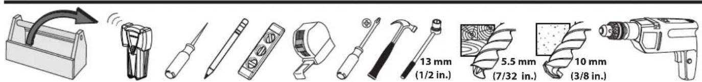
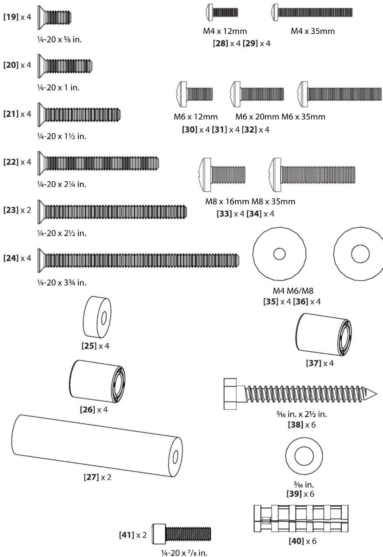
WARNING: This product contains small items that could be a choking hazard if swallowed.
Before starting assembly, verify all parts are included and undamaged. If any parts are missing or damaged, do not return the damaged item to your dealer; contact Customer Service. Never use damaged parts!
NOTE: Not all hardware included will be used.
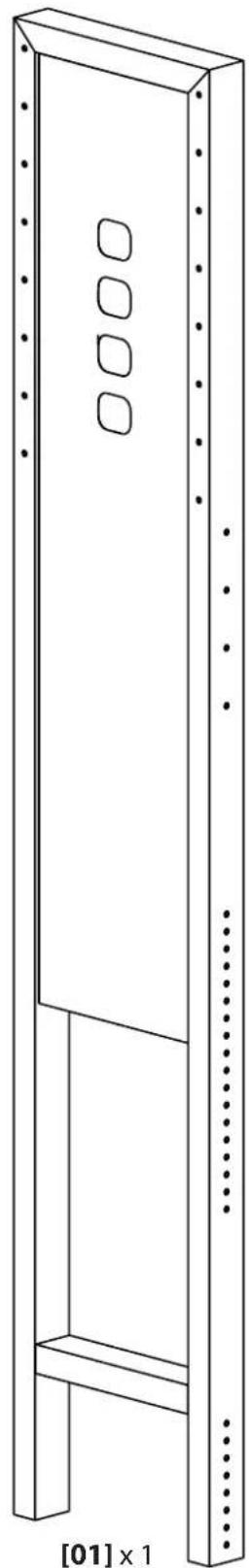
natural_image
Technical line drawing of a vertical metal shelving unit with three square cutouts, labeled [01] x 1 (no text or symbols on the diagram itself)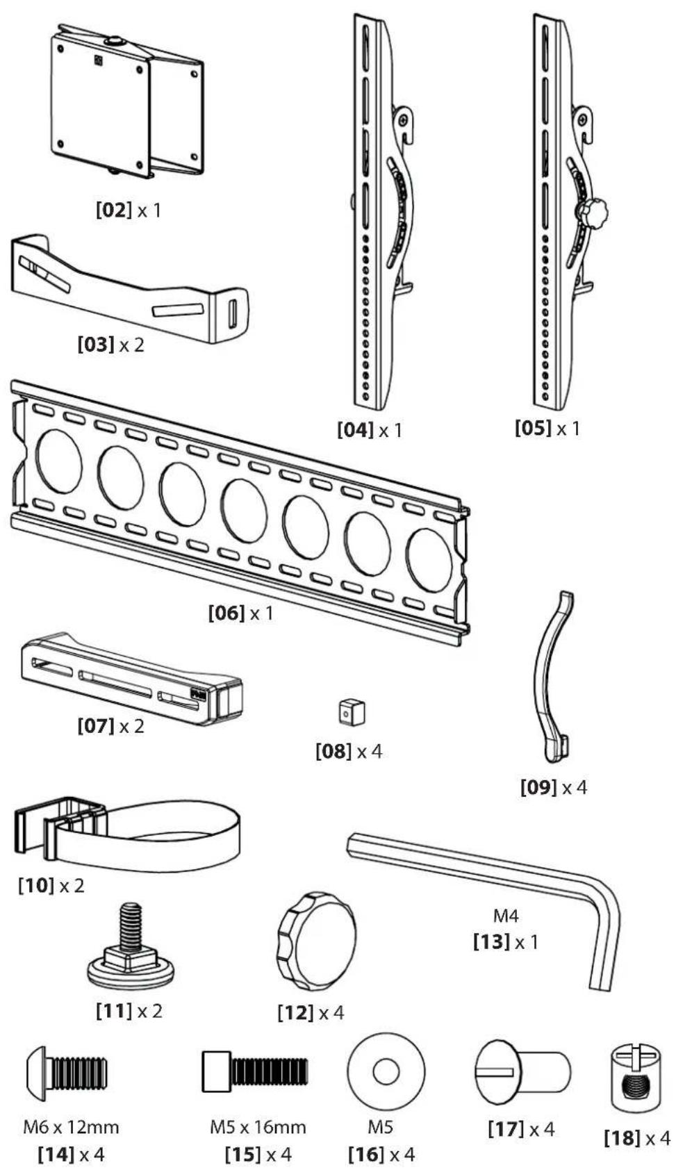
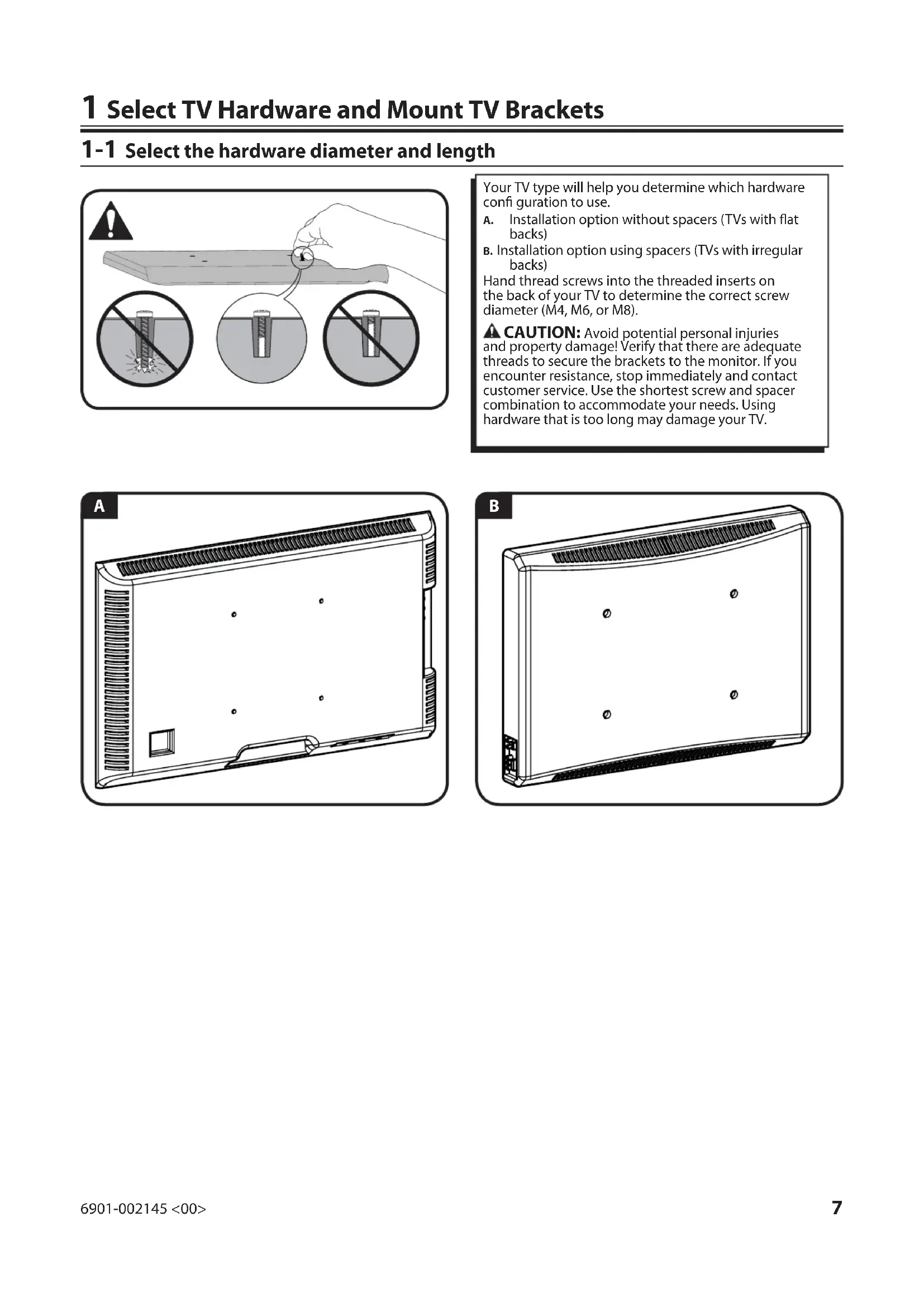
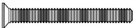
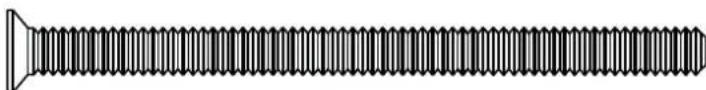
1 Select TV Hardware and Mount TV Brackets
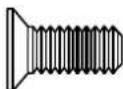
1-1 Select the hardware diameter and length
Your TV type will help you determine which hardware configuration to use.
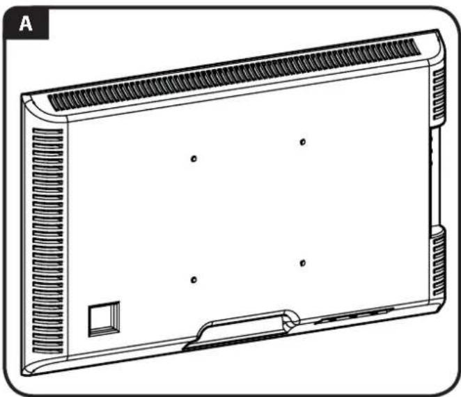
A. Installation option without spacers (TVs with flat backs)
B. Installation option using spacers (TVs with irregular backs)
Hand thread screws into the threaded inserts on the back of your TV to determine the correct screw diameter (M4, M6, or M8).
CAUTION: Avoid potential personal injuries and property damage! Verify that there are adequate threads to secure the brackets to the monitor. If you encounter resistance, stop immediately and contact customer service. Use the shortest screw and spacer combination to accommodate your needs. Using hardware that is too long may damage your TV.
natural_image
Line drawing of a rectangular electronic device with ventilation grilles and mounting brackets (no text or symbols)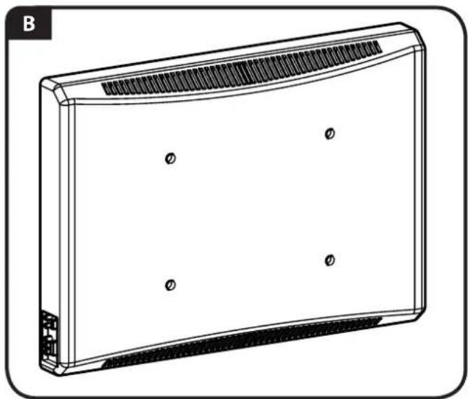
natural_image
Technical line drawing of a rectangular electronic device with ventilation grille and mounting base (no text or symbols)![A [04] [05]](/content/2026/03/444626/images/8de1b4b996c34891362129ee08028998dee33f6d8f242a6b677293be1b3b46f5.jpg)
For TVs with a fl at back
Ensure the brackets are level on the back of the TV. If you require additional space for cables, recesses, or protrusions, see configuration B.
![M4/M6/M8 [04],[05] [35],[36] [28],[30],[31],[33]](/content/2026/03/444626/images/0d9a2a9fa4f7ad8931f62c20ade68f05d5e9c178d241954e9cfd53aed45e4237.jpg)
![B [04] [05]](/content/2026/03/444626/images/66e00f3450b93fc4cb7d7f129b634ee9d2b285ffc588a07befade8fb7a224e00.jpg)
For TVs with an irregular back
Ensure the brackets are level on the back of the TV. Standard configurations are shown. For special applications, or if you are uncertain about your hardware selection, contact Customer Service.
![M4/M6/M8 [04],[05] [37] [35],[36] [29],[32],[34]](/content/2026/03/444626/images/a4f31246d1a111146208aaea250b6d0894d45bb72118a5331ff84d5c484598db.jpg)
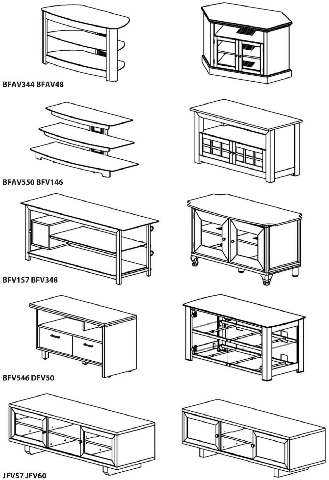
2 Attach Pillar Brackets to FMS Compatible Furniture
Determine which hardware to use - see chart on page 10.
NOTE: Not all FMS furniture is shown. If your furniture is not listed in the chart, consult the original instruction manual included with your furniture. Use the combination that will securely fasten the pillar vertically to the back of the furniture without touching the overhang.
CAUTION: The FMS01 can only be used on FMS compatible furniture. FMS compatible furniture will not require drilling or modification to mounting hardware.
For FMS compatible furniture with:
No overhang (flat back) see option A.
A small overhang, 19 mm (3/4 in.) or less, see option B.
A large overhang, 75 mm (3 in.) or less, see option C.
CAUTION: Avoid potential personal injuries and property damage! Ensure both brackets [03] are centered, level, and securely fastened to the furniture.
![[03] A [03]](/content/2026/03/444626/images/1b923827819b632aaf489fcaf60346fcfeeea470997255ea9f769d0ee859f1db.jpg)
![[26] [27] [03] B [26] [03]](/content/2026/03/444626/images/07ef05d9eebac527d32b43edd5cba6ef72af47d8953ae190648962a62fef415d.jpg)
![[03] [27] [03]](/content/2026/03/444626/images/4228702ec837478c2ee1f6d76ade0b708619d4d2641b9040747a40fc9e05b8d0.jpg)
NOTE: Refer to the FMS furniture manual for specific information regarding hardware combinations.
| Sanus TV Stand | Screw ID QTY | Spacer | D QTY | Standard Hardware | ID QTY | ||||
| BFAV344 1 | 14 - 20 × 5/8 in. [19] 4 | ||||||||
| BFAV48 | 1/4 - 20 × 2.25 in. | [22] | 4 | 1/4 - 20 barrel nut | [18] | 4 | |||
| BFAV550 1 | 14 - 20 × 5/8 in. [19] 4 | ||||||||
| BFV146 1/4 | 1/4 - 20 × 3.5 in. [24] 4 | .866 in. [26] 4 | 1/4 - 20 barrel nut | [18] 4 | |||||
| .25 in. [25] 4 | |||||||||
| BFV157 | 1/4 - 20 × 1 1/2 in. | [21] | 4 | .866 in. | [26] | 4 | |||
| BFV348 | 1/4 - 20 × 1 1/2 in. | [21] 2 | .866 in. | [26] 4 | 1/4 - 20 cap nut [17] 2 | ||||
| 1/4 - 20 × 2 1/4 in. | [22] | 2 | 1/4 - 20 barrel nut | [18] | 2 | ||||
| BFV546 | 1/4 - 20 × 2 1/4 in. | [22] | 4 | 1/4 - 20 barrel nut | [18] | 4 | |||
| DFV50 | 1/4 - 20 × 1 1/2 in. | [21] | 4 | .866 in. | [26] | 4 | |||
| JFV57 | 1/4 - 20 × 2.25 in. | [22] | 4 | 1/4 - 20 barrel nut | [18] | 4 | |||
| JFV60 | 1/4 - 20 × 2.25 in. | [22] | 4 | 1/4 - 20 barrel nut | [18] | 4 | |||
[19]
14-20×58 in.
[25]
[21]
14-20×112 in.
[26]
[17]
[22]
natural_image
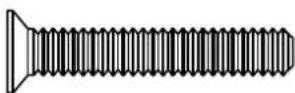
Illustration of a standard screw with threaded shaft and flange (no text or symbols)14-20×214 in.
[24]
natural_image
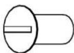
Pure illustration of a screw with no text or symbols14-20×334 in.

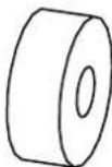
[18]
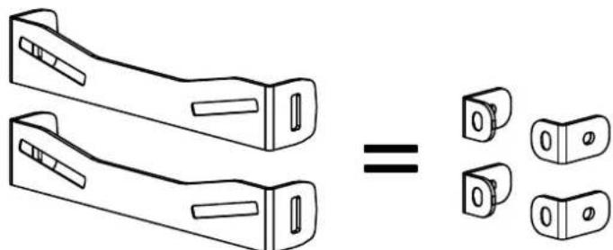
NOTE: Some FMS compatible furniture manuals may show 4 small "L" brackets for use with the pillar kit. These have been replaced with 2 one piece brackets.
3 Assemble Pillar
3-1
Attach feet [11] and pivot head [02] to pillar [01].
![[13] [14] [02] [01] [11]](/content/2026/03/444626/images/451fdbd7b91b34c61d382a7edd142f6385cfa297eb26825c085618e2d92eb4b8.jpg)
3-2
Attach wall plate [06] to pivot head [02]. Make sure to center wall plate [06] on pivot head [02].
![[13] [15] [16] [06] [02]](/content/2026/03/444626/images/f59109135f06b903825e570f6c330188bea9476a2dddddf3483d56fc2121669e.jpg)
4 Attach Pillar to Brackets
Attach pillar [01] to brackets [03] with knobs [12].
CAUTION: Avoid potential personal injuries or property damage! Ensure feet [11] are level and firmly on the floor.
![[12] [03] [12] [01] [03] [03] [11] [11]](/content/2026/03/444626/images/3e0f57d4b5506bba121bbff925a9139af8711f86fc3770956f99501a5c2dc169.jpg)
![[11]](/content/2026/03/444626/images/534c45017086d2cab24af1624df6d2637cd8e6a77f610958f910cc621677dbeb.jpg)
![[11]](/content/2026/03/444626/images/0f4218bc86d6c8668220c862fa74761f459c5d7ea0aac013d1457b954fdc1787.jpg)
5 Attach and Secure TV to Wall Plate
![5-1 Attach TV to wall plate [06]. Assistance is recommended for this step. [06]](/content/2026/03/444626/images/2b1e35e03f0bc5a9f1b656e4e04d99081929b630390d052d3f9d0078638c162c.jpg)
![Install locking screws [41]. CAUTION: Avoid potential personal injuries or property damage! Be sure to install the locking screws [41]. [41]](/content/2026/03/444626/images/da23d387e17013a1a74b2c746852b4f530ceeb07254c5e4e3f44fd3b9f570a3a.jpg)
6 Adjust Tilt Tension
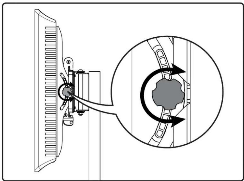
natural_image
Diagram showing a mechanical device with a close-up inset illustrating the rotational motion of a gear mechanism (no text or symbols present)SANUS®
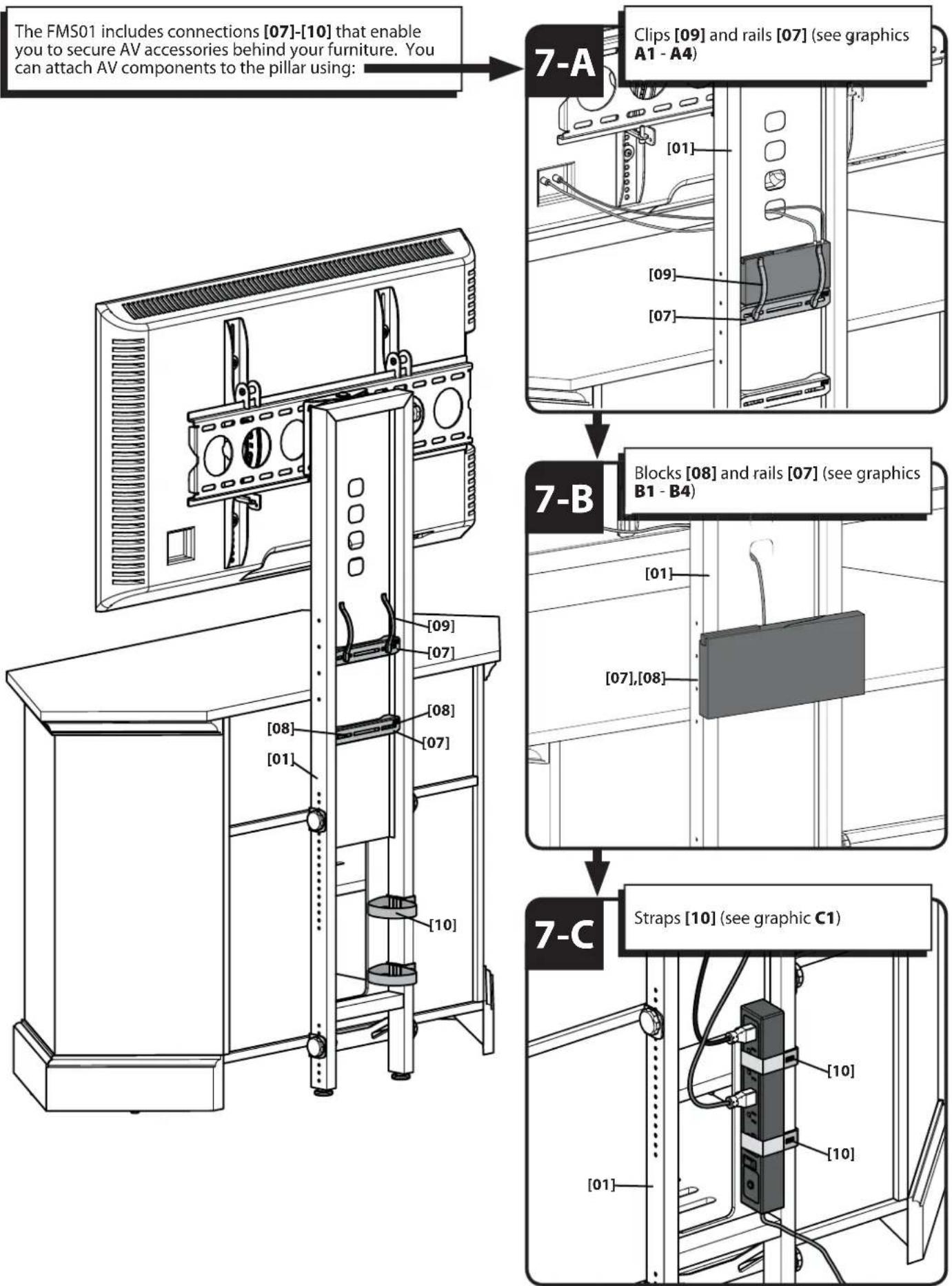
7 Attach FMS Connections for AV Accessories

flowchart
graph TD
A["The FMS01 includes connections [07"]-["10"] that enable you to secure AV accessories behind your furniture. You can attach AV components to the pillar using:] --> B["7-A"]
B --> C["Clips [09"] and_rails["07"] (see graphics A1 - A4)]
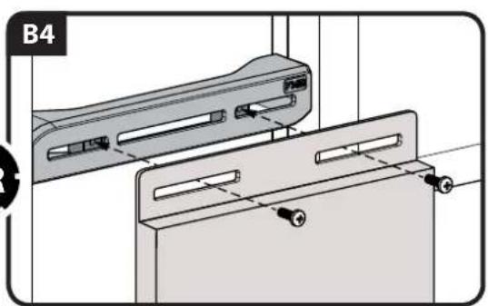
B --> D["Blocks [08"] and_rails["07"] (see graphics B1 - B4)]
B --> E["Straps [10"] (see graphic C1)]
![A1 [01] [07]](/content/2026/03/444626/images/c7c02f1135648803a6c42eee570711c22bbf7bdc377e3cc0ef46d11c8b98a72c.jpg)
![A2 [01] [07]](/content/2026/03/444626/images/74e7937feb13970b88b9724240a252425d379cb25a009c821e8eed52c64dd640.jpg)
![A3 [01] [07] [09]](/content/2026/03/444626/images/79bb06c5b41b54447e0013d759621197d0d42b63c631a9f25d8283b5e5aefab3.jpg)
![A4 [01] [07] [09]](/content/2026/03/444626/images/4442af4ac6bdf204298900dfeda074781b058f10bbc0d7bde4c9825bf100ef0e.jpg)
![B1 B [08] [07] [28 or 29]](/content/2026/03/444626/images/8ecad83f658e0992a95d7d1b1f19430a35c1d493282e20f808b6d7f1ec14fa0e.jpg)
![[07] [08] [28 or 29] Leave a small space for keyhole mounting.](/content/2026/03/444626/images/f0fb8e6007201d567fda602d433f0467cdd7aefad151154fe94fdcda3aec1e5b.jpg)
![B3 [01] [07] [28 or 29]](/content/2026/03/444626/images/f5ecbcf92657e4a7d51d304b316223f7054010cff91300b155a91da8f6dbab55.jpg)
![C1 [01] [10] [10]](/content/2026/03/444626/images/0de7aa1d6849b60450137fe9eaa9157ea7cb80213c6ad0f4e8bf762003cb7308.jpg)
8 Mount to Wall
Wood Stud
8-1 Locate studs
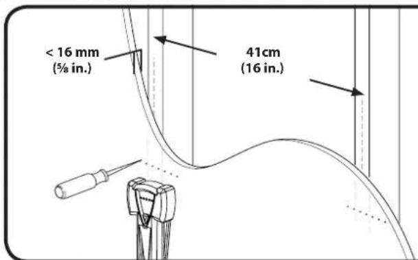
Verify the center of the stud(s) using an awl, a thin nail, or an edge to edge stud fi nder.
CAUTION: Avoid potential personal injuries and property damage!
■ Any material covering the wall must not exceed 16 mm (5/8 in.).
Minimum wood stud size: common 51 x 102 mm (2 x 4 in.) (Nominal 38 x 89 mm {1½ x 3½ in.})
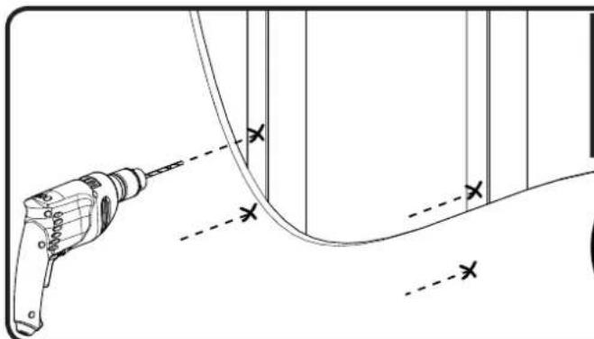
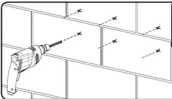
8-2 Mark the wall
![[06]](/content/2026/03/444626/images/11693b0f7d11122d213e69393844d9185d29057ef4999a8cfd3e1b9e4f82e25f.jpg)
Level the wall plate [06] and mark the hole locations.
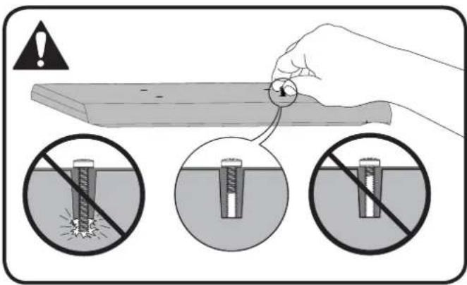
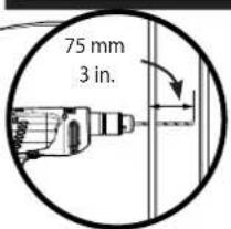
8-3 Drill pilot holes
natural_image
Technical line drawing of a drill bit with no text or symbols⚠️ CAUTION: Improper use could reduce the holding power of the lag bolt. To avoid potential injuries or property damage: pilot holes MUST be drilled to a depth of 75 mm (3 in.), using a 5.5 mm (7/32 in.) diameter drill bit.
8-4 Tighten lag bolts
![[06] [38] [39]](/content/2026/03/444626/images/153f90128dc390b69227bc2f9056f9b419567a640c7b473dcc82647ad086167a.jpg)
CAUTION: Avoid potential injuries or property damage! Improper use could reduce the holding power of the lag bolt. To avoid potential injuries or property damage:
DO NOT over-tighten the lag bolts [38]
- Tighten the lag bolts [38] only until the washers [39] are pulled firmly against the wall plate [06]
8 Mount to Wall
Solid concrete or concrete block
8-1 Mark the wall
![[06]](/content/2026/03/444626/images/cf7a19e56430402b50e54a291bb2baddd010ac379d855638a5f79adfdd0445a1.jpg)
Level the wall plate [06] and mark the hole locations.
▲ CAUTION: Avoid potential injuries or property damage!
Mount the wall plate [06] directly onto the concrete surface.
Minimum solid concrete thickness: 203 mm (8 in.).
Minimum concrete block size: 203 x 203 x 406 mm (8 x 8 x 16 in.)
Minimum space between fasteners: 203 mm (8 in.)
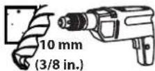
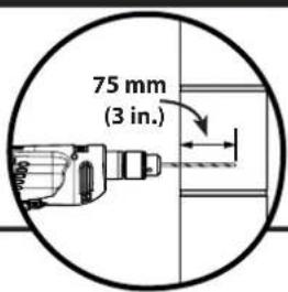
8-2 Drill pilot holes
natural_image
Line drawing of a drill bit on a cabinet shelf with dashed alignment lines (no text or symbols)CAUTION: To avoid potential injuries or property damage:
- Pilot holes MUST be drilled to a depth of 75 mm (3 in.) using a 13 mm (1/2 in.) diameter drill bit.
■ Never drill into the mortar between blocks.
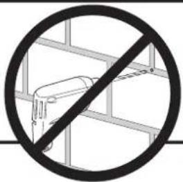
8-3 Insert anchors
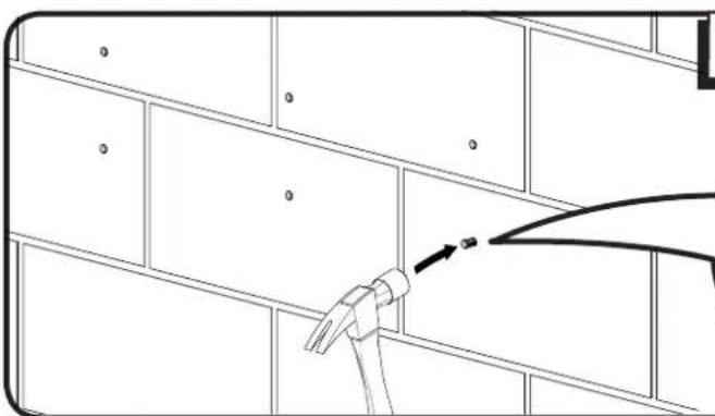
natural_image
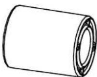
Line drawing of a hand holding a tool against a wall-mounted shelf, with no visible text or symbolsInsert lag bolt anchors [40].
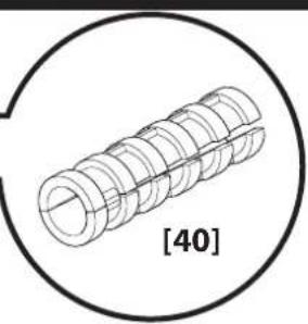
natural_image
Technical line drawing of a helical screw or threaded component enclosed in a circle, labeled [40] (no text or symbols on the diagram itself)8-4 Tighten lag bolts
![[06] [39] [38]](/content/2026/03/444626/images/8a2e5c08ade17db024c2822a61183cf1ca9290453b8d30ad13c1557f0cafeabc.jpg)
CAUTION: Avoid potential injuries or property damage! Improper use could reduce the holding power of the lag bolt. To avoid potential injuries or property damage
DO NOT over-tighten the lag bolts [38].
- Tighten the lag bolts [38] only until the washers [39] are pulled firmly against the wall plate [06].
9 Attach and Secure TV to Wall Plate
![9-1 Attach TV to wall plate [06]. ● Assistance is recommended for this step. [04,05] [06]](/content/2026/03/444626/images/e950154946df001ee58889b53d6446ec18c1f0571ead105ed7ccf78ca239e7f4.jpg)
![9-2 Install locking screws [41] with hex key [13]. CAUTION: Avoid potential personal injuries or property damage! Be sure to install the locking screws [41]. [41] [13]](/content/2026/03/444626/images/ddeb9e2d198f81f9a8b23419baa43fd659eee2ea2a54e9f73ce67064a154ad33.jpg)
10 Adjust Tilt Tension
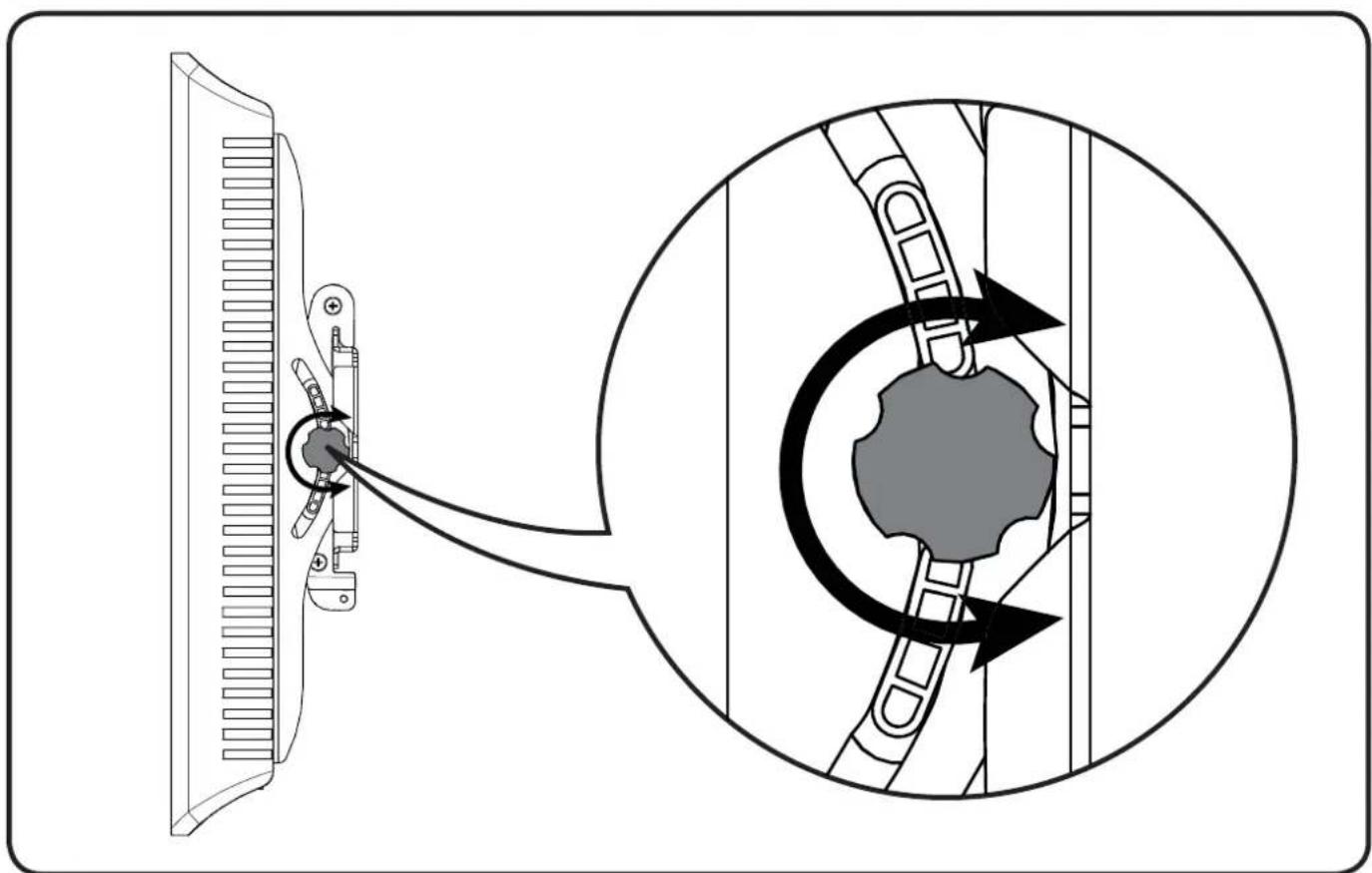
natural_image
Diagram showing a mechanical device interacting with a gear mechanism, with an inset illustrating the motion of the mechanism (no text or symbols present)SANUS®
Français
CONSIGNES DE SÉCURITÉ IMPORTANTES – CONSERVEZ CES INSTRUCTIONS – VEUILLEZ LIRE ATTENTIVEMENT LE MANUEL AVANT D'UTILISER CE PRODUIT
8-3 Insira as âncoras
Milestone AV Technologies and its affiliated corporations and subsidiaries (collectively, "Milestone"), intend to make this manual accurate and complete. However, Milestone makes no claim that the information contained herein covers all details, conditions, or variations. Nor does it provide for every possible contingency in connection with the installation or use of this product. The information contained in this document is subject to change without notice or obligation of any kind. Milestone makes no representation of warranty, expressed or implied, regarding the information contained herein. Milestone assumes no responsibility for accuracy, completeness or sufficiency of the information contained in this document.