SATPLUS 4 - Signal analyzer Telestar - Free user manual and instructions
Find the device manual for free SATPLUS 4 Telestar in PDF.
| Product type | Signal analyzer and digital measurement receiver |
| Brand | TELESTAR |
| Model | SATPLUS 4 |
| Frequency ranges | Satellite: 950-2150 MHz; DVB-C/-T/-T2: 48-862 MHz |
| Supported standards | DVB-S/S2x/T/T2/C, MPEG-2, H.264/AVC, H.265/HEVC (10 bits) |
| Display | LCD TFT 480x3 (RGB), 154,08 x 85,92 mm |
| Power supply | Lithium-Ion battery 5 Ah, 7,4 V; mains adapter 12 V/1,5 A; car charger |
| Dimensions (W × H × D) | 346 × 299 × 100 mm |
| Weight | 3,1 kg |
| RF inputs | Satellite (F) 75 Ω; DVB-T/T2/C (F) 75 Ω |
| Video inputs | HDMI 1.3a, AV (3.5 mm jack), optical (FC/ST/LC) |
| Video outputs | HDMI 1.3a, AV (3.5 mm jack), DC 12 V for external devices |
| Ports | USB 2.0, LAN RJ45 |
| Measurement functions | Level (PWR), MER, BER, C/N, constellation diagram, spectrum, automatic transponder test |
| Measurement modes | Satellite (DVB-S/S2), terrestrial (DVB-T/T2), cable (DVB-C), optical (850-1550 nm) |
| Special functions | Screenshot, program recording, video monitor, USB backup, firmware update |
| LNB commands | 22 kHz, DiSEqC 1.0/1.1, Tone Burst, supply 13/18 V (max 400 mA) |
| DVB-T/T2 antenna power supply | 5 V, 12 V or 24 V (max 100 mA) |
| Maintenance and cleaning | Disconnect the device, clean with a soft dry cloth, do not use liquids |
| Safety | Do not open the housing, use only the supplied adapter, keep out of reach of children |
| Spare parts and repairability | Contact TELESTAR customer service (service@telestar.de); repairs by qualified personnel only |
| General information | Legal warranty, technical hotline: 02676/9520101 (Mon-Fri 8:00-16:45) |
Frequently Asked Questions - SATPLUS 4 Telestar
User questions about SATPLUS 4 Telestar
0 question about this device. Answer the ones you know or ask your own.
Ask a new question about this device
Download the instructions for your Signal analyzer in PDF format for free! Find your manual SATPLUS 4 - Telestar and take your electronic device back in hand. On this page are published all the documents necessary for the use of your device. SATPLUS 4 by Telestar.
USER MANUAL SATPLUS 4 Telestar
The terms HDMI and HDMI High-Definition Multimedia Interface, and the HDMI Logo are trademarks or registered trademarks of HDMI Licensing Administrator, Inc. in the United States and other countries.
Rechtlicher Hinweis
MER-Messung (Modulation Error Rate)
MER-Messung (Modulation Error Rate)
Farbnormen PAL, SECAM, NTSC
Video Format 4:3, 16:9, By Pan & Scan and Letter Box
Conversion
Audio Dekompression MPEG-1 Layer 1/11, M.PEG-2 Laye, 1/11
Audio Ausgang Stereo, Mono, R/L
Operating instructions

Digital DVB-S/S2/T/T2/C measuring receiver
- FOREWORD 4
2.SAFETYINSTRUCTIONS 5
2.1 Explanation of symbols. 5
2.2 Intended use 6
2.3 Safety instructions 6
2.4 Operational safety 7
2.5 Connecting the device 7
2.6 Protect the device from defects 7
2.7 Handling batteries 8
2.8 Cleaning the appliance 8
2.9 Behavior in the event of malfunctions.. 8 - SCOPE OF DELIVERY 9
4.DEVICE OVERVIEW 10
4.1 Control panel and connections 10 - First commissioning 14
5.1.Insertion 12
5.2. Menu 12
5.2.1 System settings. 13
6.SAT MEASURING RANGE. 15
6.1.DVB-S/S2 preset 15
6.2.DVB-S/S2 measurement.. 16
6.3.DVB-S/S2 Spectrum 18
6.4. Constellation 18
6.5. Transponder Auto Test function 19
6.6.Update satellite channel list 20 - DVB-T/T2 - DVB-C MEASURING RANGE 21
7.1.DVBT/T2 DVB-C measurement.. 22
7.2.DVB-T/T2/DVB-C spectrum 23
7.3.DVB-T/T2/DVB-C constellation. 24
8.PROGRAM LIST 25
8.1. Edit programs 25
8.2. Backing up the program list to a USB data carrier.. 27
8.3.Import program list via USB 28 - SPECIAL FUNCTIONS 29
9.1. Saving settings to USB / USB backup 29
9.2.Factory settings. 30
9.3.Screenshot function.. 30
9.4. Program recording 31
9.5. Video monitor function 31 - TECHNICAL DATA 33
11.DISPOSAL NOTE. 37
11.1. Disposal of packaging 37
11.2. Disposal of the appliance 37
11.3. Disposal of batteries 37 - CE LABELING 38


1. FOREWORD
Dear customer,
Thank you for choosing this product.
Our product complies with legal requirements and has been manufactured under constant quality control.
The technical data correspond to the current status at the time of printing.
Subject to change without notice.
The warranty period for the device corresponds to the statutory provisions at the time of purchase. We also offer you our telephone HOTLINE service with professional help. In our service area, professional experts are available to answer your questions. Here you can ask any questions you may have about the products and get tips on localizing the cause of a possible fault.
Our technicians are available from Monday to Friday from 8.00 a.m. to 4.45 p.m. on the following telephone number:
Technical hotline:
02676/9520101
or by e-mail at: service@telestar.de
If the Service Hotline is unable to help you, please send the device to the following address in its original packaging, if possible, but packed securely for transportation:
TELESTAR-DIGITALGmbH
Service Center
Am Weiher 14 (industrial area)
56766 Ulmen
Please read these instructions carefully and keep them for future reference. If you sell or pass on the appliance, please also hand over these operating instructions.
Trademark information
The terms HDMI and HDMI High-Definition Multimedia Interface, and the HDMI Logo are trademarks or registered trademarks of HDMI Licensing Administrator, Inc. in the United States and other countries.
Legal notice
All the information in these operating instructions
The technical data and functions described are correct at the time of going to press and are subject to change without prior notice. We accept no liability for printing errors and mistakes. Copying and reproduction is only permitted with the express permission of TELESTAR-DIGITAL GmbH. Status: 09/2023
2. SAFETY INSTRUCTIONS
2.1 Explanation of symbols
SYMBOL MEANING

DANGER!WARNING!
This signal word indicates a hazard with a high degree of risk that will result in death or serious injury if the warning is ignored.
This signal word indicates a hazard with a medium level of risk which, if not avoided, could result in death or serious injury.
EN

CAUTION!
This signal word indicates a hazard with a low level of risk which, if not avoided, may result in minor or moderate injury.

NOTE!
This signal word warns of possible material damage.

This symbol warns of danger.
Protection class II
Electrical appliances with protection class II have reinforced or double insulation at the level of the rated insulation voltage between active and touchable parts (VDE 0100 Part 410, 412.1). They usually have no connection to the protective conductor. Even if they have electrically conductive surfaces, these are protected from contact with other live parts by reinforced or double insulation.

The products marked with this symbol fulfill the requirements of the European Community directives.

Fig. 1
Fig. 2

For devices with hollow plugs, these symbols indicate the polarity of the plug.
A distinction is made here between 2 variants
Fig 1: Outside plus/inside minus
Fig 2: Inside plus / outside minus
Appliances with this symbol may only be operated indoors in a dry environment

2.2 Intended use
The device serves as a measuring receiver for audio / video signals transmitted via satellite, DVB-T/2 and DVB-C. Any other operation or use of the device is considered improper and may result in personal injury or damage to property. Do not use the device for any other purpose.
Only operate the appliance indoors.
The device is intended for private use only and not for commercial use. We assume that the operator of the device has general knowledge of handling consumer electronics devices.
Liability expires in the event of improper use.
' Only use spare parts and accessories supplied or approved by us.
Do not modify the appliance and do not use any accessories or spare parts that have not been explicitly approved or supplied by us.
Do not use the appliance in potentially explosive atmospheres.
These include, for example, fuel storage areas, tank facilities or areas where solvents are stored or processed.
Do not operate the appliance in areas with particle-laden air (e.g. flour or wood dust)
Do not expose the device to extreme conditions, e.g. direct sunlight, high humidity, moisture, extremely high or low temperatures, naked flames.
2.3 Safety instructions
Check the device before use.
In the event of damage or a defect, the appliance must not be put into operation. Risk of injury!
Risk of injury for children and persons with reduced physical, sensory or mental capabilities (e.g. partially disabled persons, elderly persons with reduced physical and mental capabilities) or lack of experience and knowledge.
' Please only store the device in places that are inaccessible to children.
This appliance can be used by children aged from 8 years and above and persons with reduced physical, sensory or mental capabilities or lack of experience and/or knowledge if they have been given supervision or instruction concerning use of the appliance in a safe way and understand the hazards involved.
' Never allow children to use the appliance unsupervised.
' Please do not store the packaging materials used (bags, polystyrene pieces, etc.) within the reach of children. Children must not play with the packaging. There is a risk of suffocation, especially with packaging films.
2.4 Operational safety

DANGER!
Risk of injury!
Risk of injury due to electric shock from live parts.
There is a risk of electric shock or fire due to an unintentional short circuit.
' Please check the appliance for damage before each use. If you notice any visible damage or the appliance is visibly damaged, please do not use it.
' If you notice a technical or mechanical problem, please contact TELESTAR Service.
' Only use the power supply unit included in the scope of delivery!
' Never open the housing of the appliance.
' In the event of malfunctions, disconnect the appliance from the power source immediately
' If you move the appliance from a cold to a warm environment, moisture may condense inside the appliance.
In this case, wait about an hour before operating it.
' Unplug the appliance from the socket if you are going to be away for a long time or during a thunderstorm.
' If foreign bodies or liquid get into the appliance, unplug the power supply unit from the socket immediately. Have the appliance checked by qualified personnel before putting it back into operation. Otherwise, there is a risk of electric shock.
2.5 Connecting the device
' Only connect the appliance to a properly installed, earthed and electrically fused socket.
' Please ensure that the power source (socket) is easily accessible.
Do not kink or crush any cable connections.
' Before putting the appliance into operation, check whether the voltage information on the appliance corresponds to the local mains voltage.
2.6 Protecting the device from defects

NOTE!
Unfavorable ambient conditions such as humidity, excessive heat or lack of ventilation can damage the device. Only use the device in dry rooms. Avoid direct proximity to: Heat sources, such as radiators, open flames, such as candles, devices with strong magnetic fields, such as loudspeakers. Ensure sufficient distance from other objects so that the device is not covered, so that adequate ventilation is always guaranteed. Avoid direct sunlight and places with an unusually high level of dust.
Ensure that contact with moisture, water or splashing water is avoided and that no objects filled with liquid - e.g. vases - are placed on or near the appliance. Do not place any heavy objects on the appliance.
Ensure that the appliance is not exposed to dripping or splashing water and that there are no open sources of fire (e.g. burning candles) near the appliance.

2. SAFETY INSTRUCTIONS
2.7 Handling batteries
The device contains a rechargeable battery. Only use this type of battery for the remote control. Only ever use the battery type included in the scope of delivery.

DANGER!

There is a risk of internal injury if batteries are swallowed.
The battery acid in the batteries can cause injuries if it comes into contact with the skin.
Seek medical help immediately if there are signs of skin burns. Always keep new and used batteries away from children. Remove leaking batteries from the appliance immediately and clean the contacts before inserting new batteries.

WARNING!
There is a risk of explosion if batteries are used incorrectly.
Only use new batteries of the same type. Never use new and old batteries together in the same device.
Ensure that the batteries are correctly polarized when inserting them. Batteries should only be stored in cool and dry places. Never throw batteries into a fire.
If the device is not to be used for an extended period of time, please remove the batteries from the device. Never expose batteries to extreme heat or direct sunlight.
2.8 Cleaning the appliance
Disconnect the appliance from the power supply before cleaning. Use a dry, soft cloth to clean the appliance. Please do not use any liquids to clean the appliance. Do not use any solvents or cleaning agents, as these can damage the surface and/or labels of the appliance.
2.9 Behavior in the event of malfunctions
If the device malfunctions, disconnect it from the power supply and wait a few seconds. Reconnect the device to the power supply.
It may be necessary to reset the device to the factory settings. If this is not successful, please contact your dealer or contact TELESTAR Digital GmbH directly.
You can also find more information on page 6.
Please remove all parts from the packaging and completely remove all packaging materials.
If one or more of the
If the parts listed are missing, please contact the TELESTAR
Service Center
Am Weiher 14,
56766 Ulmen
e-mail: service@telestar.de
NUMBER EXPLANATION
1
2 Operating instructions
3 External power supply unit
4 AVadapter cable
5 Car charging adapter
6 Carrier bag
7 12 Volt DC connection cable
8 RF connector
4.1 Control panel and connections
EN
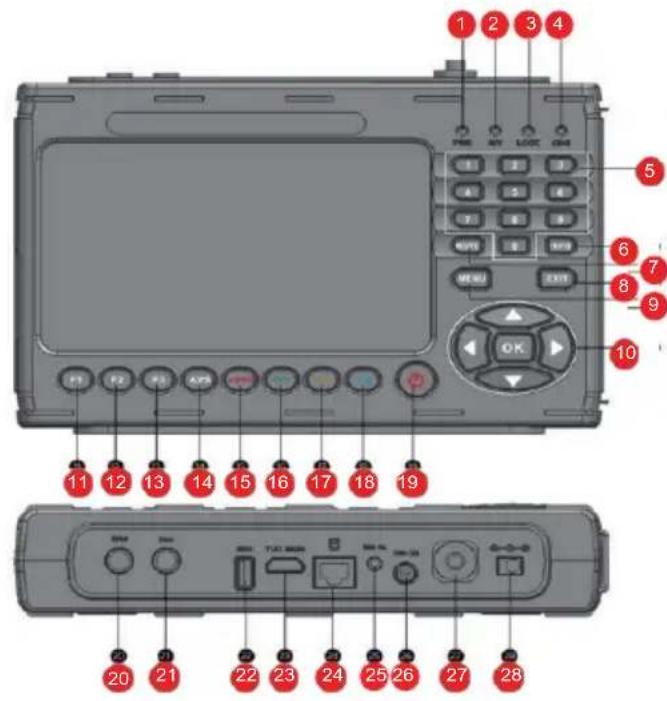
NO.DESCRIPTIONFUNCTION
PWR Power LED. Lights up red during operation.
1
Polarization status:
2
Red-horizontal (18V) / Green-vertical (13V)
3
LOCK Signal is present. Data stream is being received.
4
CHG Battery control status Yellow: Battery is charging.
5
Push-button door For direct input of a value.
6
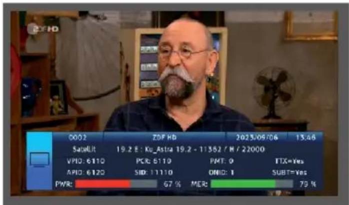
INFO Calls up the reception parameters of a set P program.
7
MUTE Mutes the loudspeaker.
8
EXIT Exits the selected menu.
9
MENUCallsupthemenu.Pressingagain switchescback one menu item.
1C
Navigation cross
For navigation in the menu. OK button Confirms a selection
11
Calls up different functions depending on the operating mode.
F2 Calls up different functions depending on the operating mode.
12
4.1 Control panel and connections
NO.DESCRIPTIONFUNCTION
| 13 | F3 Calls up different functions depending on the operating mode. | |
| 14 | AVS Switches to external input source | |
| 15 | Function Red AUDIO | Calls up various functions in the menu. Calls up audio parameters. |
| 16 | Function Green TV/R | Calls up various functions in the menu. Switches between TV and radio mode. |
| 17 | Function Orange SAT | Calls up various functions in the menu. Calls up measurement parameters inSat reception. |
| 18 | Blue function Calls up various functions in the menu. SYS | |
| 19 | STANDBY | Switches the device on or off. |
| 20 | Sat RF input | Antenna connection Satellite reception system |
| 21 | DVB-T/T2 / DVB-C HF input | RF connection for measuring DVB-T/T2 or DVB-C signals. |
| 22 | USBconnection | USB connection for updating the device with a new firmware and to save a station list, to save a channel list, to save a Screenshots or to record a TV program. |
| 23 | HDMI Out | HDMI output for outputting the screen content to an external monitor with HDMI connection. |
| 24 | LAN connection | RJ 45 LAN interface |
| 25 | AV Out | AV output for outputting the screen content to an external monitor with an analog AV connection. (Adapter cable included in the scope of delivery) |
| 26 | DC Out | 12 V voltage output for operating external devices with 12 V power supply. (e.g. surveillance camera) |
| 27 | Optical connection For power measurement of optical signals | |
| 28 | Voltage Power supply scope of delivery) | Connection of the external power supply unit or car power supply unit (included in the |
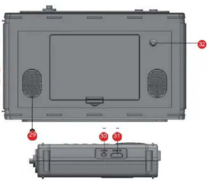
4.1 Control panel and connections
| 29 | Loudspeake | |
| 30 | AV IN | For connecting an external audio-video playback device, e.g. surveillance camera with analog output. |
| 31 | HDMI IN | For connecting an external audio-video playback device with HDMI output. |
| 32 | LED Light for illumination in difficult lighting situations. |
5.1 Introduction
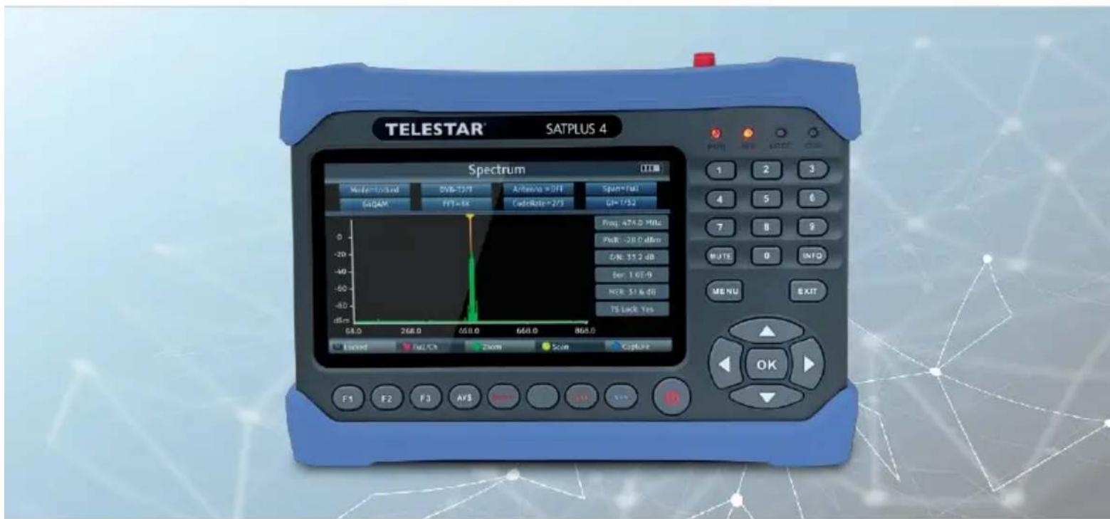
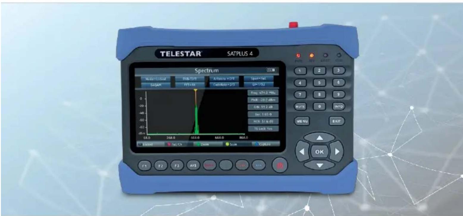
With the TELESTAR SATPLUS 4, you are able to set up and align a satellite system optimally and easily. You can also use the device to measure DVB-C and DVB-T/DVB-T2 signals. Before using the device for the first time, the battery should be charged. The first charging process should take at least 4 hours. The measuring receiver can also be charged when it is switched on.
Connect the 230V mains adapter to the mains adapter connection on the side of the device and plug the mains adapter into a mains socket. the device is now charging. The CHG LED lights up.
Switch the device on using the power button. During the boot process, all 4 control LEDs at the top right light up. After the start logo, the device is ready for operation.
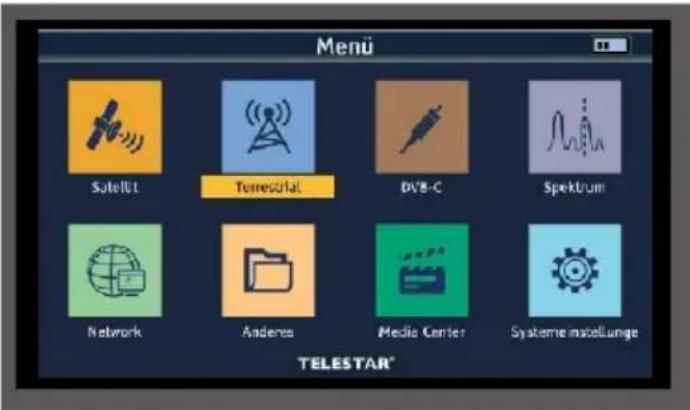
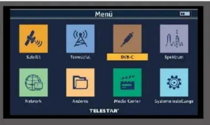
5.2 Menu
Press the MENU button.
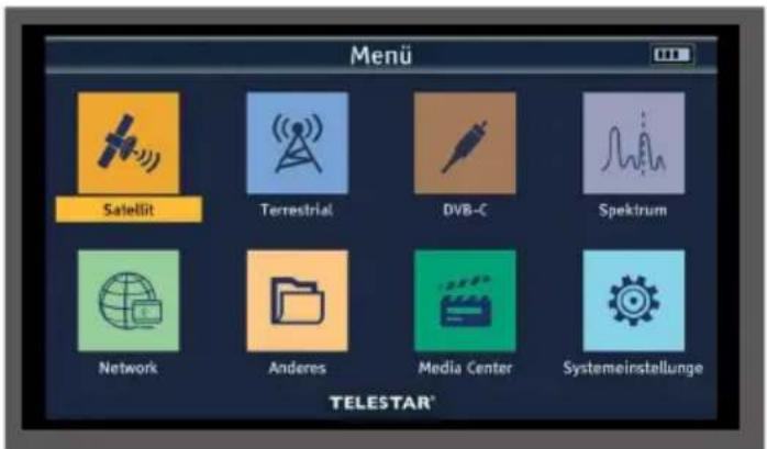
You can use the navigation cross to select all menu items in the menu. The selected menu item is highlighted in color and you can call up the selected menu item by pressing the OK button. To exit the menu, press the EXIT button. To go back one step in the menu, press the MENU button.
5. FIRST COMMISSIONING
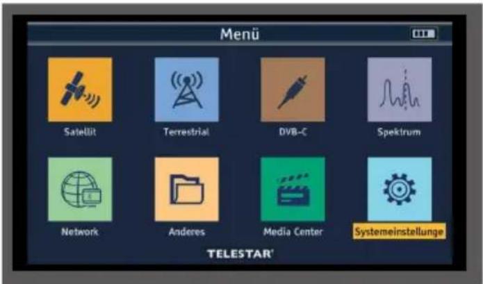
5.2.1 System settings
If you are using the device for the first time, you may need to change the basic settings of the receiver; you can make these basic settings in the Settings area.
Use the navigation cross to select the System settings menu item and confirm with OK.
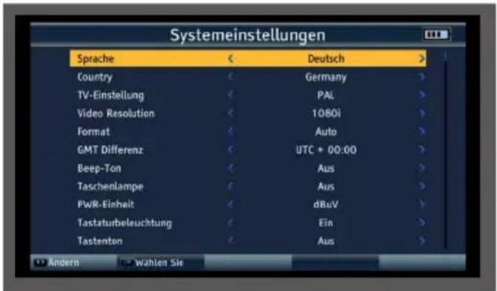
5.2.1 System settings
Language:
Select the menu language here. You can choose between German, Italian, Spanish, Polish, Arabic, Indonesian, English, French, Russian, Portuguese and Turkish.
Country:
Select the country you are in here.
TV setting
Here you can choose between the PAL and NTSC TV systems.
Video resolution
Select the resolution of the device monitor and the resolution transmitted via HDMI here. Choose between the standard resolutions 576p, 720p, 1080i and 1080p.
Format
The various display formats can be set here.
GMT Difference
Set the time zone for your location here. For Germany, this difference is GMT+1 hour.
Beep tone
An acoustic signal can be activated here during level measurement. The shorter the distance between the beeps, the stronger the signal.
Flashlight
Switch the LED on the back of the device on or off here.
PWR unit
Specify here whether the signal measurement should be displayed in dBuv or dBmV. The difference between dBmV and dBuV is that dBmV is measured in decibels relative to a millivolt, while dBuV is measured in decibels relative to a microvolt.
Keyboard illumination
The setting activates the keyboard backlighting.
Key tone
An acknowledgement tone can be activated here when the buttons on the device are pressed.
5.2.1 System settings
Loudspeaker
Activate or deactivate the built-in speaker under this menu item.
12V
Switch the 12 volt output voltage for external devices on or off here.
Childproof lock
The device offers the option of providing programs and menu settings with a PIN query. This security can be activated here.
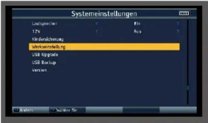
Factory setting
You can reset all settings that you have made on the device to their original state using the factory settings. This is useful if you have made changes that subsequently lead to the appliance not functioning optimally.
USB upgrade
You can use the USB interface to update the device's operating software, which can be downloaded from www.telestar.de if required.
The software provided on the website must be unpacked. The unpacked file is then copied to an appropriate storage medium and connected to the measuring receiver via USB.
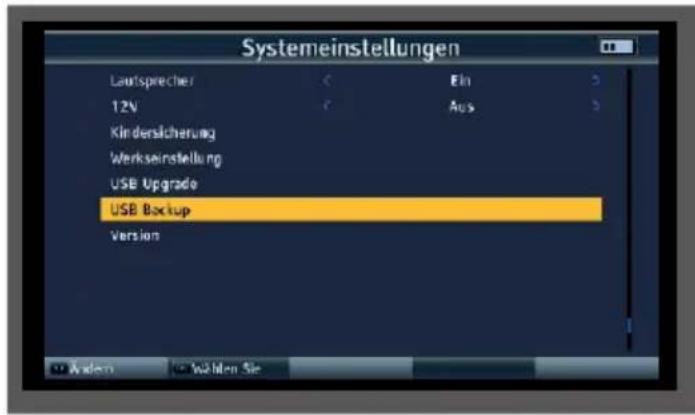
USB backup
This menu item can be used to perform a program list backup to a USB data carrier connected to the device.
Version
To check the current software version of the receiver, the information can be called up via this menu item.
6. SAT-MEASURING RANGE
6.1 DVB-S/S2 default setting
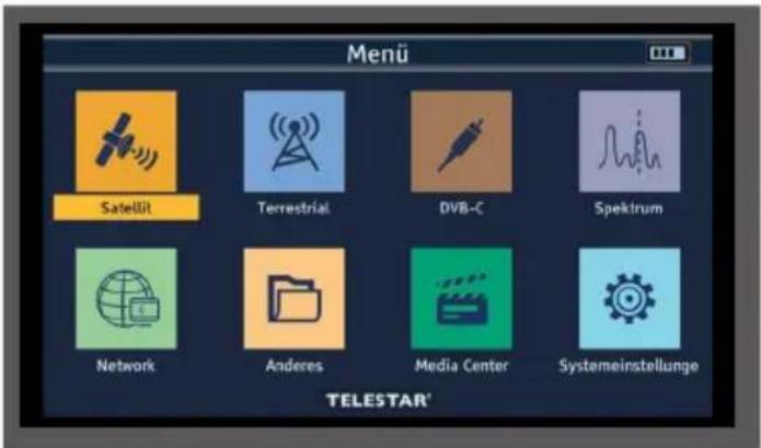
The device can be used to optimally align the satellite antenna. In addition, the following setting can be used to perform a search to save programs for the satellite to be received.
Connect the antenna cable to the measuring receiver at the LNB input.
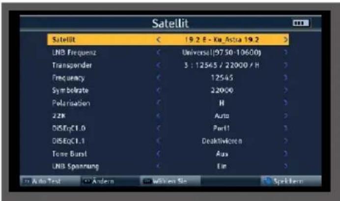
Select the Satellite menu item in the main menu and confirm with OK.
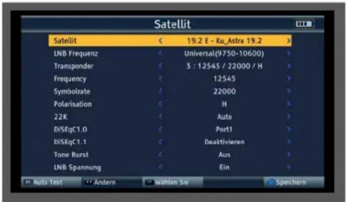

Satellite
In the Satellite line, select the satellite position to which the satellite system is to be aligned or on which a measurement is to be carried out.
LNB frequency
In the LNB line, you can use the left/right arrow buttons to select the LNB with which the satellite position is to be received. The standard setting is Universal (9750-10600) The device automatically switches between KuLOW and Ku-HIGH when RF input is made. The threshold for switching to the high band is 11.7 GHz. After entering the transponder frequency, the device issues the corresponding DiSEqC or 22kHz switching commands.
Transponder
Select the transponder on which the receiver should receive a signal from the selected satellite.
Frequency
You can change the frequency of the selected transponder if required. Enter the frequency in this line using the numeric keypad. To accept the change, press the blue button (SYS).
Symbol rate
To adjust the symbol rate if necessary, switch to the Symbol rate line and enter the value using the numeric keypad.
Polarization
If required, switch between horizontal (H/V LED red) and vertical (H/V LED green) here.
22K
The measuring receiver controls a connected LNB or a multi-switch via the conventional 14/18 V -22 kHz control (max. 4 SAT IF levels) or with DiSEqC control. The supply delivers a maximum of 500mA . With the LNB setting Universal (9750 - 10600), the 22kHz setting cannot be changed.
6. SAT MEASURING RANGE
6.1 DVB-S/S2 default setting
DiSEqC 1.0 / 1.1
In these fields, use the navigation cross to set the satellite position that is controlled via DiSEqC. This setting depends on the satellite reception system and the associated modules.
Tone Burst

Switch the tone burst here according to the connected satellite system. This setting depends on the satellite reception system and the associated modules.
LNB voltage
The LNB power supply (14/18V) can be switched on or off via this menu item.
6.2 DVB-S/S2 measurement
Press the OK button during operation. The preset program list is called up.
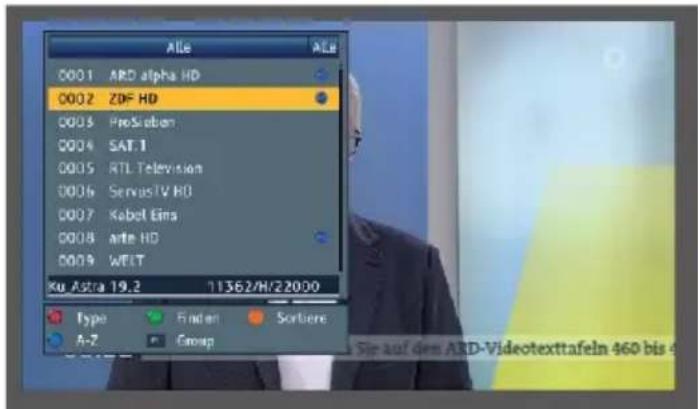
Select a program on which a measurement is to be carried out and confirm with OK.
6. SAT MEASURING RANGE
6.2 DVB-S/S2 measurement
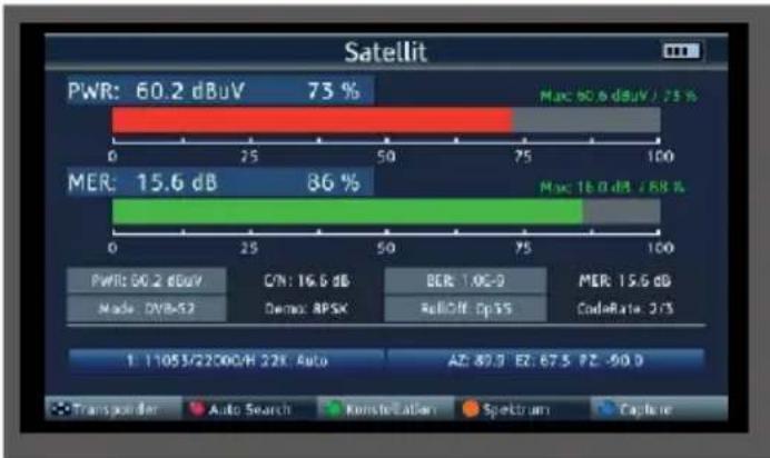
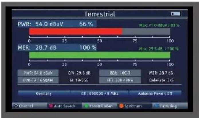
Press the SAT button. The measured values of the selected program are displayed.
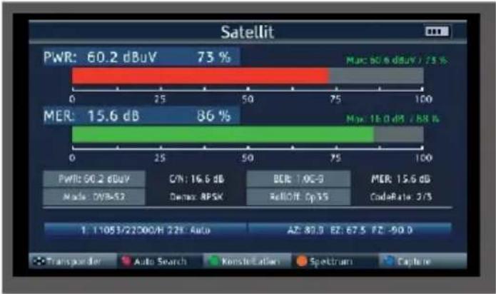

PWR
The level measurement starts as soon as the measuring receiver is tuned. The measured level is displayed in dB V with 0.1 dB resolution
MER
MER measurement (Modulation Error Rate)
The MER is calculated from the constellation points.
It is the counterpart to S/N measurement for analog transmission methods. The measuring range extends up to 20 dB with a resolution of 0.1 dB.
BER
The measurement of the bit error rate is used to assess the quality of a DVB signal.
The error correction mechanisms in the digital receiver are used to determine the bit error rate. The data stream before and after correction is compared and the number of corrected bits is determined. This number is set in relation to the total number of bits passed through and the BER is calculated from this.
C/N
Carrier-to-noise, carrier-to-noise ratio
The distance between the carrier and the noise is measured. A good C/N is
a prerequisite for all other qualities BER, MER RollOff
The roll-off factor generally describes the edge steepness when filtering a signal. In satellite transmission, the roll-off factors are used to define the edge steepness of the DVB-S2 signal. The lower the number, the lower the required frequency bandwidth. However, this also reduces the signal-to-noise ratio and therefore the transmission reliability. For DVB-S, a roll-off factor of 0.35 is generally used.
CodeRate
The CodeRate shows information on the forward error correction (FEC) used for the DVB signal. Forward error correction takes place as part of channel coding. Redundancy is added to the digital and initially source-coded signal on the transmitter side in a channel encoder to enable the channel decoder in the receiver to correct errors that have occurred on the transmission channel. The value of the FEC expresses the ratio of useful bits to transmitted bits. In this image, 2 of the 3 transmitted bits are useful bits.
Demo
Displays the modulation method used on this transponder.
6. SAT MEASURING RANGE
6.3 DVB-S/S2 spectrum
In addition to the measured values, you can also call up the spectrum of a defined frequency range.
If you are in satellite measurement mode, press the orange button (SAT) to activate the display of the frequency spectrum.
or
In the main menu, switch to the Spectrum item, confirm with OK and select the reception path on which you want to display the spectrum.

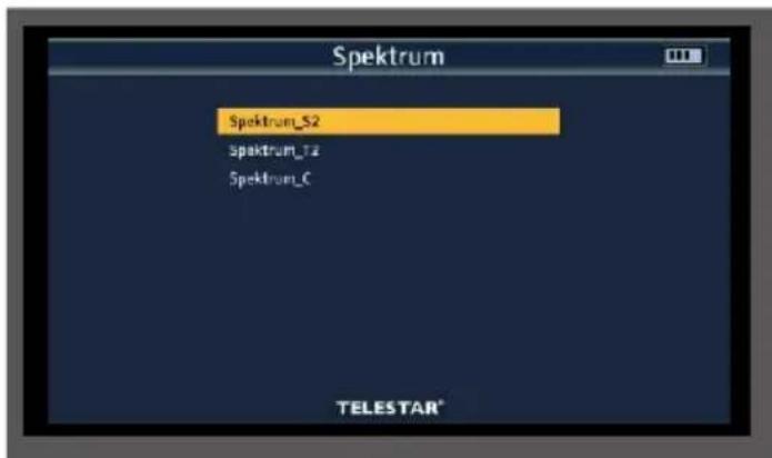
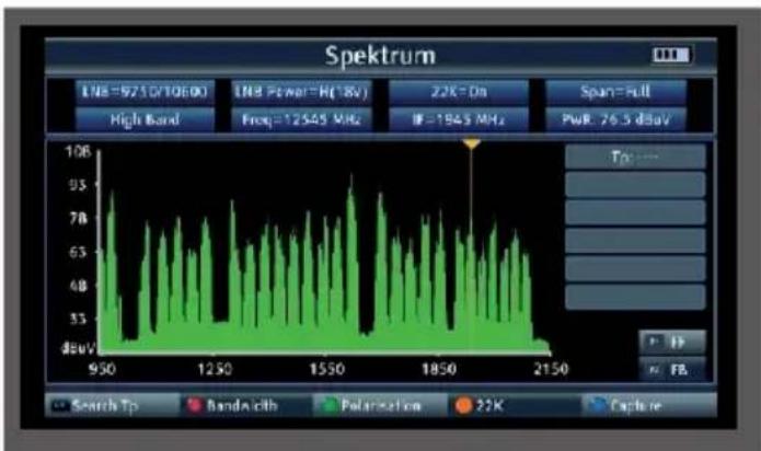
You will now see the entire frequency spectrum of the reception area.
Using the red button (AUDIO), the frequency section (span) can be changed in 3 steps: 300Mhz, 600MHz, Full (entire spectrum).
You can use the navigation cross to move the cursor to any position. A level measurement (PWR) is carried out at the current position of the cursor.
6.4 Constellation
The constellation diagram is used to display the modulation type.
In the ideal case - interference-free transmission - the data is recognized correctly and appears in the Constellation diagram as clearly defined points, each exactly in the center of the corresponding quadrant. However, interference in the transmission channel often means that the receiver cannot correctly interpret some of the data in the received signal. Therefore, the points do not appear exactly in the theoretical center of the grid, but a larger scattering of the points becomes visible in the constellation diagram. The display on the screen is adjusted for each modulation type. For example, a DVB-C 16QAM signal is displayed on the screen with a total of 16 quadrants, a DVB-C 64 QAM signal with a total of 64 quadrants.
6. SAT MEASURING RANGE
6.4 Constellation
Press the green button (TVR) during satellite measurement
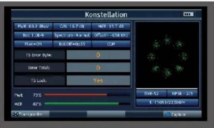
You can select the stored transponders using the navigation cross.
6.5 Transponder Auto Test function
The device can carry out an evaluation of all transponders of a satellite position.
This gives you an overview and a check of all available transponders for a satellite position.
Select "Satellite" in the main menu.
Press the F1 button (Auto Test)
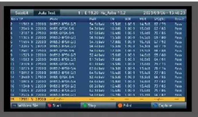
The device checks all stored Trasnponders for the set satellite position and displays the corresponding reception parameters.
6. SAT MEASURING RANGE
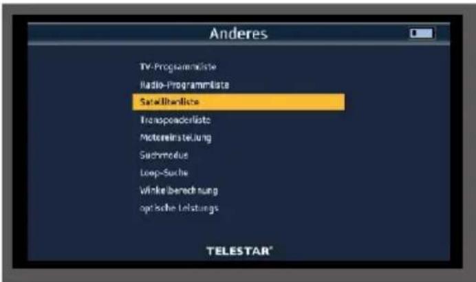
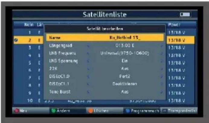
6.6 Updating the satellite channel list
The device comes from the factory with a preset channel list of the satellite position Astra 19.2 degrees East. You can add other satellite positions to this channel list.
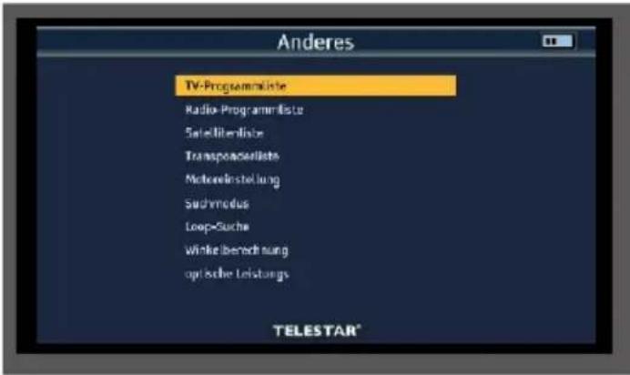
Select "Other" in the main menu and confirm with OK.
Select "Satellite list" and confirm with OK.
Select the satellite position from the list on which a channel search is to be carried out.
Press the OK button.

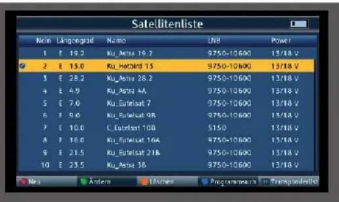
If required, press the green button (Change) to check the reception settings of the satellite system or to change them if necessary. Press MENU to exit this item.
Press the blue button (program search). Select "Search" and confirm with OK.
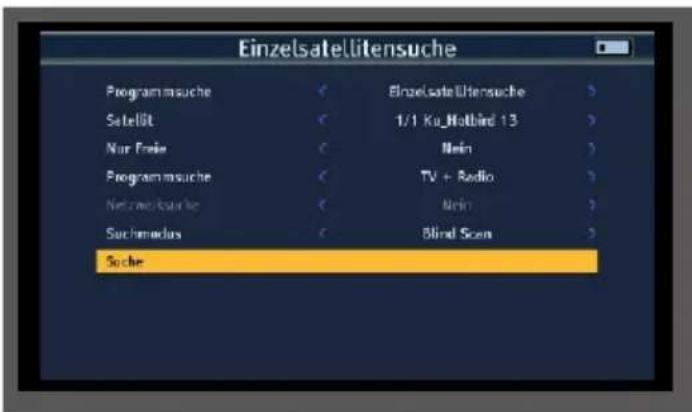
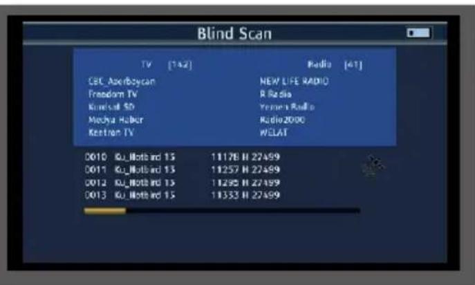
The device saves all programs found in the main program list.
7. DVB-T/T2 - DVB-C MEASURING RANGE
To carry out a measurement in the DVB-T/T2 or DVB-C range, please select the DVB-T menu or DVB-C menu item in the main menu and confirm with OK.
Please note in the DVB-T/T2 range:
If you have an active antenna that you operate on the device, you can activate an antenna supply voltage via the device's coax input here.
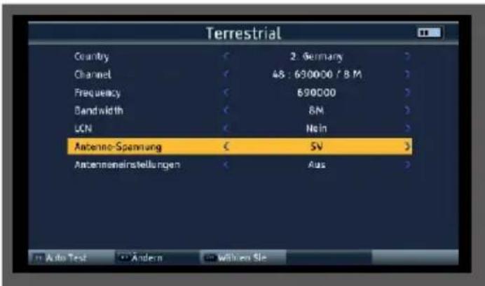
Please also inform yourself about the technical specifications of your antenna.
To do this, select the Antenna setting line and use the right/left navigation buttons to switch the supply voltage on or off.

NOTE!
The supply voltage can be set between 5 volts, 12 volts and 24 volts.
Please also inform yourself about the technical specifications of your antenna.
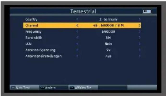
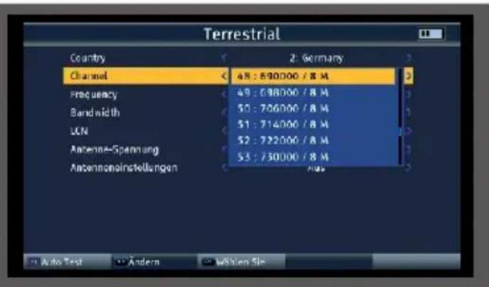
In the Channel line, select the frequency on which a measurement is to be carried out.
Use the navigation buttons right/left to call up the channel list.
7. DVB-T/T2 - DVB-C MEASURING RANGE
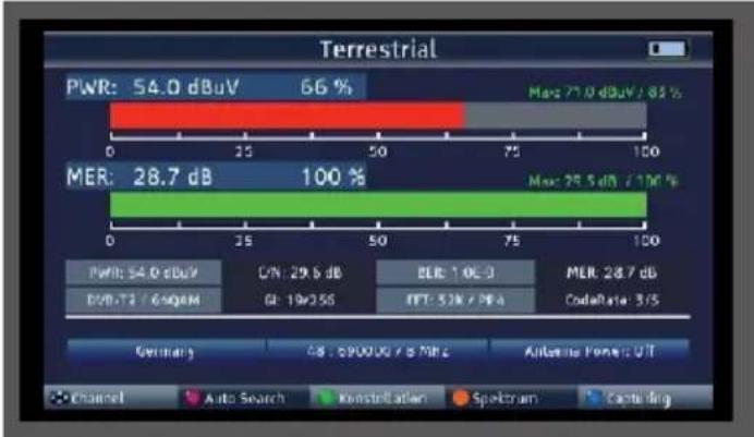
7.1 DVBT/T2 DVB-C measurement
Press the OK button to start the measurement.
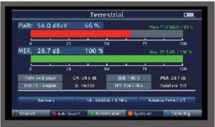
PWR
The level measurement starts as soon as the measuring receiver is tuned. The measured level is displayed in dB V with 0.1 dB resolution
MER
MER measurement (Modulation Error Rate)
The MER is calculated from the constellation points.
It is the counterpart to S/N measurement for analog transmission methods. The measuring range extends up to 20 dB with a resolution of 0.1 dB.
BER
The measurement of the bit error rate is used to assess the quality of a DVB signal. The error correction mechanisms in the digital receiver are used to determine the bit error rate. The data stream before and after correction is compared and the number of corrected bits is determined. This number is set in relation to the total number of bits passed through and the BER is calculated from this.
C/N
Carrier-to-noise, carrier-to-noise ratio
The distance between the carrier and the noise is measured. A good C/N is a prerequisite for all other qualities BER, MER FFT
Displays the FFT mode used.
GI
Displays the protection interval used.
CodeRate
The CodeRate shows information on the forward error correction (FEC) used for the DVB signal. Forward error correction takes place as part of channel coding. Redundancy is added to the digital and initially source-coded signal on the transmitter side in a channel encoder to enable the channel decoder in the receiver to correct errors that have occurred on the transmission channel. The value of the FEC expresses the ratio of useful bits to transmitted bits. In this image, 3 of the 5 transmitted bits are useful bits.
You can use the right/left navigation buttons to change the channel in the measuring nest.
7. DVB-T/T2 - DVB-C MEASURING RANGE
7.2 DVB-T/T2/DVB-C spectrum
In addition to the measured values, you can also call up the spectrum of a defined frequency range.
If you are in DVB-T/T2 or DVB-C measurement, press the orange button (SAT) to activate the display of the frequency spectrum.
or
In the main menu, switch to the Spectrum item, confirm with OK and select the reception path on which you want to display the spectrum.
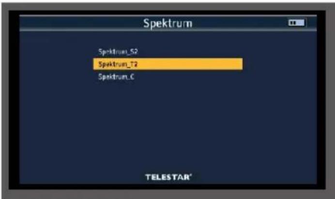
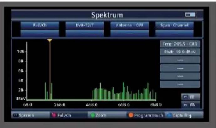
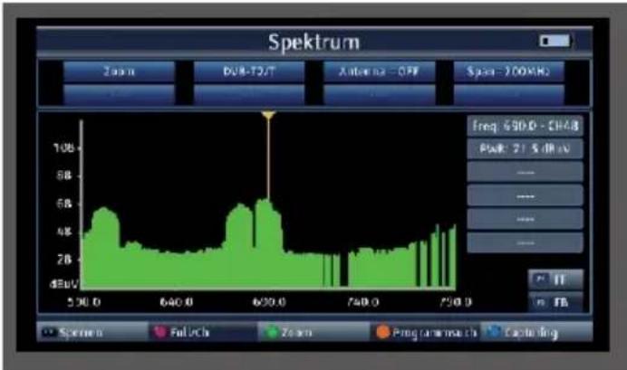
You will now see the entire frequency spectrum of the reception area.
The frequency section can be changed using the green button (TV/R).
You can use the navigation cross to move the cursor to any position. A level measurement
(PWR) is carried out at the current position of the cursor.
7.3 DVB-T/T2/DVB-C constellation

The constellation diagram is used to display the modulation type.
In the ideal case - interference-free transmission - the data is recognized perfectly and appears in the constellation diagram as clearly defined points, each exactly in the middle of the corresponding quadrant.
However, interference in the transmission channel often means that the receiver cannot correctly interpret some of the data in the received signal. Therefore, the points do not appear exactly in the theoretical center of the grid, but a larger scattering of the points becomes visible in the constellation diagram.
The display on the screen is adapted for each modulation type. For example, a DVB-C 16QAM signal is displayed on the screen with a total of 16 quadrants, a DVB-C 64 QAM signal with a total of 64 quadrants.
Press the green button (TVR) during the measurement
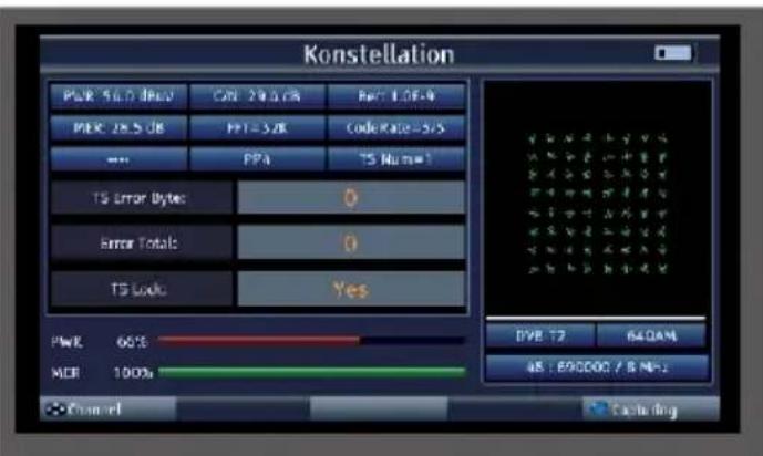
You can select the stored transponders using the navigation buttons on the right/left.
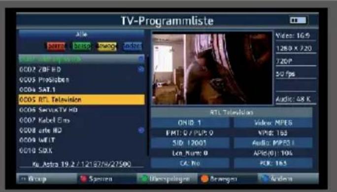
8.1 Editing programs
You can edit the saved programs according to various criteria.
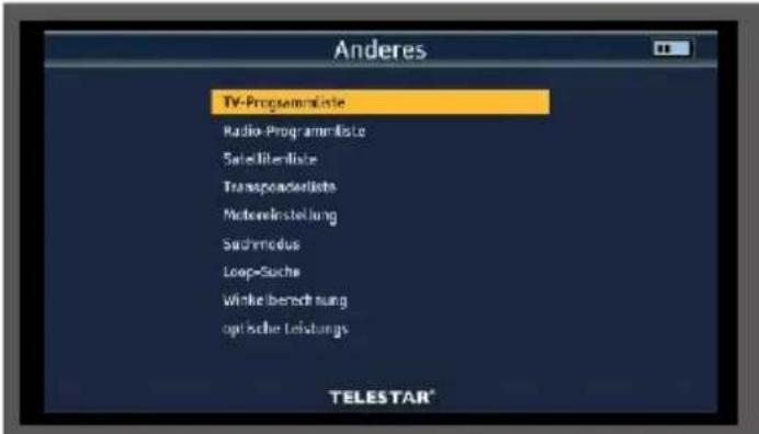
Select the "Other" menu item in the main menu using the navigation cross and confirm with OK.
Select the "TV channel list" menu item and confirm with OK.
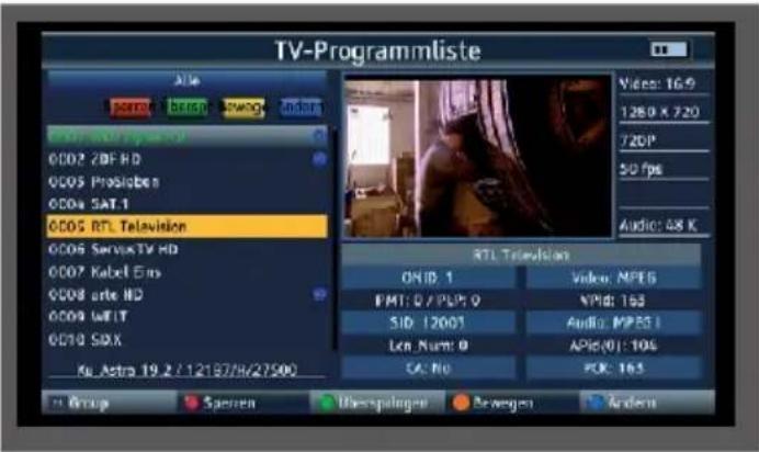
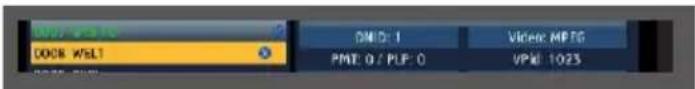
Change program sequence
To change the order of the programs, programs can simply be moved.
Use the navigation cross to select a program that you would like to move to a different position.
Press the orange SAT button (move)
Then press the OK button.
An icon appears next to the program name.
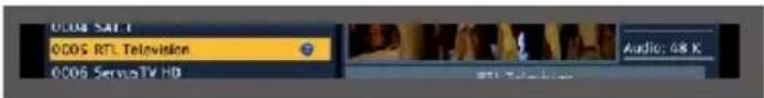
Move the yellow cursor to the position where you want to save the selected program.
Press the INFO button.
The program is now moved to the desired position.
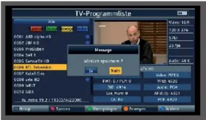
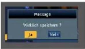
Press the MENU button and confirm the prompt with Yes if you want to save the changes you have made.
8.1 Editing programs
Deleting programs from the list
You can delete one or more preset programs or existing programs in the receiver.

NOTE!

This setting deletes all selected programs! To store programs in the device again, please carry out a new search or reset the device to the factory settings.
Select the "Other" menu item in the main menu using the navigation cross and confirm with OK.
Select the "TV channel list" menu item and confirm with OK.
Use the navigation cross to select a program that you want to delete.
Press the blue SYS button (change)
Press the blue SYS (delete) button again.
Then press the OK button.

Press the OK button.
An icon appears next to the program name.
Press the MENU button twice.
Confirm the prompt with Yes if you want to delete the program and press OK.
The program is then deleted from the program list.
8.PROGRAM LIST
8.2 Backing up the program list to a USB data carrier
If you have changed the order of programs according to your wishes or deleted or added channels from the list, you can save these changes to a USB data carrier so that you can restore this data to the measuring receiver during a factory reset.
Connect a USB data carrier to the device.
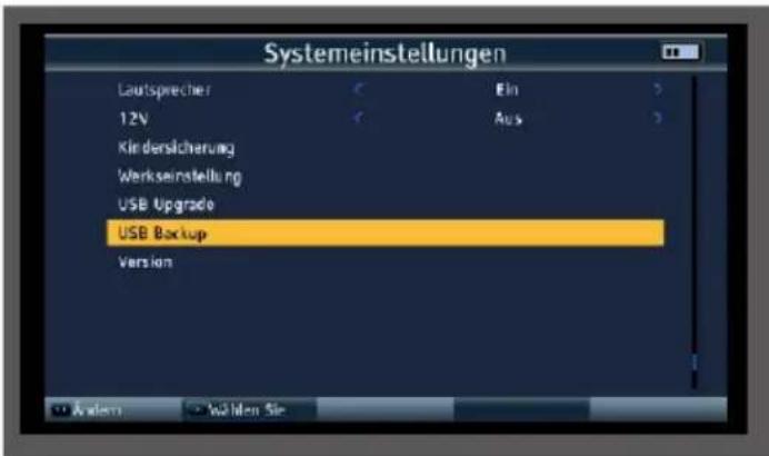
Select the System settings menu item in the main menu using the arrow button and confirm with OK.
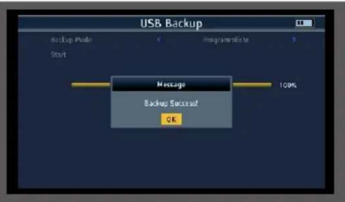
Select the Backup menu item and confirm with OK.
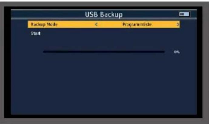
Use the navigation buttons on the right/left to select the program list in the Backup mode line.
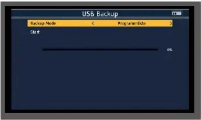
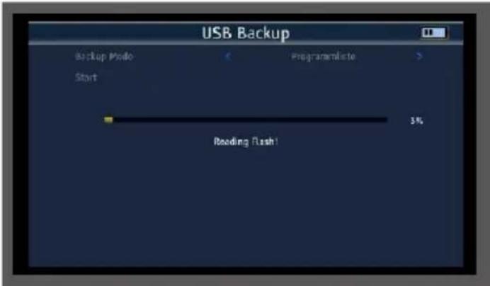
> Switch to the Start line and press OK.
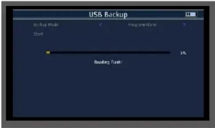
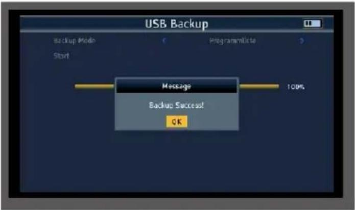
The program data is written to the USB data carrier. After successful transfer to the USB stick, a message appears which must be acknowledged by pressing the OK button.
8.3 Importing a program list via USB
A program list saved on USB can be imported into the device.
Connect a USB data carrier to the device on which you have saved a program list as described in chapter 8.2.
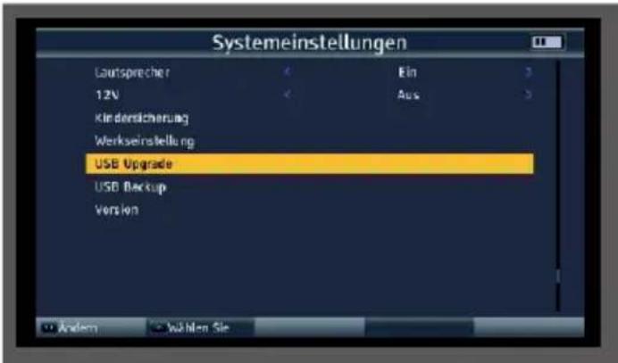
Select the System settings menu item in the main menu using the arrow button and confirm with OK.
Select the USB Upgrade menu item and confirm with OK.
Use the navigation buttons on the right/left to select the program list in the Upgrade Mode line.
EN
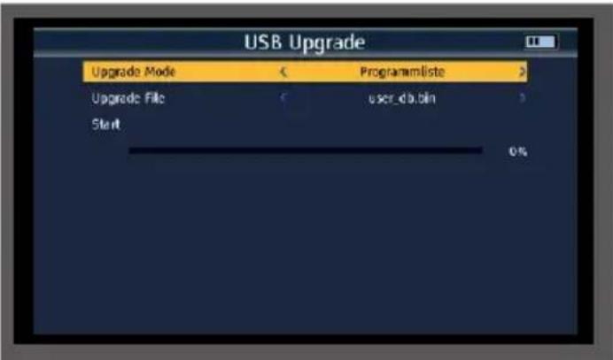
Switch to the Start line and press OK.
Confirm the prompt with Yes if you want to import the program list on the USB.
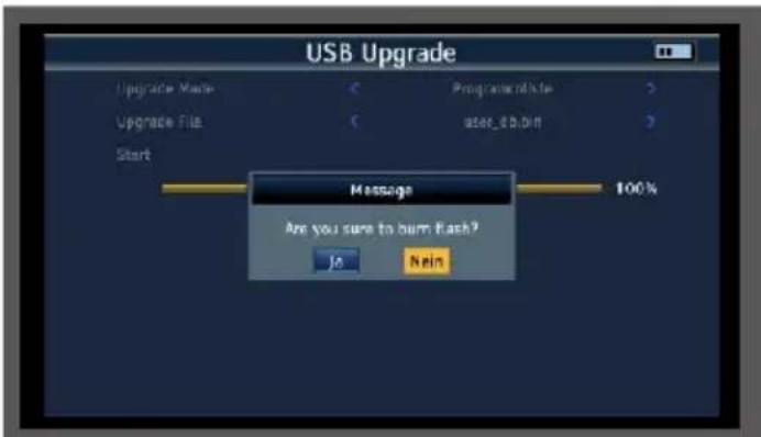
After successfully transferring the program list, the device restarts.
ATTENTION!
Please do not disconnect the USB storage medium from the device under any circumstances during the charging process!
9.1 Saving settings to USB / USB backup
Changes made to the device, such as changes to the satellite reception parameters, can be saved to a USB data carrier.
This data can be uploaded to the measuring receiver again after a factory reset.
Connect a USB data carrier to the device.
Select the System settings menu item in the main menu using the arrow button and confirm with OK.
Select the Backup menu item and confirm with OK.
Use the navigation buttons on the right/left to select the program list in the Backup mode line.
Switch to the Start line and press OK.
The program data is written to the USB data carrier. After successful transfer to the USB flash drive, a message appears which must be acknowledged by pressing the OK button.
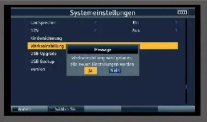
9.2 Factory settings
You can reset the device to the factory settings.
NOTE!
Please note that all settings and program list changes will be lost with this procedure.
Select the System settings menu item in the main menu using the arrow button and confirm with OK.
Select the Factory settings menu item and confirm with OK.
Confirm the prompt with Yes if you want to carry out a factory setting.
9.3 Screenshot function
The screenshot function allows you to save measured values displayed on the device as an image file. This illustration can be used as documentation for the customer.
To be able to save images, a USB data carrier must be connected to the device.
To save the currently displayed measurement or display as an image, press the blue (SYS) catpuring button. The measurement image is saved as a .bmp file on the USB data carrier.
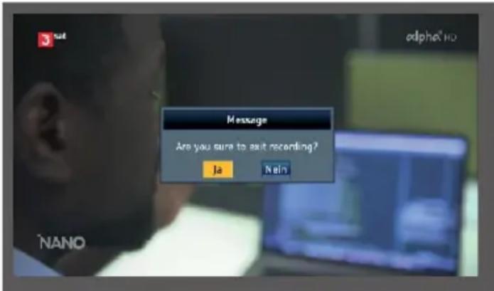
9.4 Program recording
You can record a running radio or TV program onto a connected USB data carrier.
To do this, press the F1 button during a running program. To stop the recording, press the EXIT button and confirm the prompt with Yes.

9.5 Video monitor function
You can use the device as a video monitor.
For example, you can use the device to align a surveillance camera or check an HDMI or analog video signal.
To do this, connect an AV cable or an HDMI cable from a video source to the AV or HDMI input of the device and connect the cable to an audio/video source.
The RCA-BNC adapter included in the scope of delivery allows you to adapt the plug connection if required.
Press the AVS button to activate the HDMI input of the device.
Press the AVS button twice to activate the analog audio/Vldeo input.
If you want to set up a surveillance camera or other video output device with 12 volt operating voltage, you can use the DC power cable included in the scope of delivery. This allows the video device to be supplied with operating voltage via the SATPLUS 4
9.6 Perform optical measurement

DANGER!
Incorrect commissioning of the appliance can lead to serious injury or damage to the appliance.
The device may only be operated by personnel who have received the necessary training in handling electrical and optical devices and who have been instructed in the use of lasers.
If prescribed by the hazard class, use approved eye protection devices.
Do not point the fiber optic cable at other persons.
If eye protection is required for the work to be carried out, use only approved protective equipment.
Cover all unfinished ends that correspond to a performance above hazard class 1 individually or together when no work is being carried out on them.
Only use approved covers or cover materials.

9. SPECIAL FUNCTIONS
When using optical test leads, connect the optical energy source as the last device and disconnect it as the first device.
Never make unauthorized modifications to fiber optic systems or associated devices.
If possible, switch or disconnect optical transmission or test equipment to the lowest possible power before working on optical fibers.
If fiber optic cables or connections need to be visually inspected, ensure that they do not transmit optical energy.
Never look directly into a beam and never use non-approved collimators to inspect fiber optic ends or connection surfaces.
Connect the SATPLUS 4 to the optical fiber to be measured via the optical input.
Select the "Other" menu item in the main menu using the navigation cross and confirm with OK.
Select the "Optical power measurement" menu item and confirm with OK.
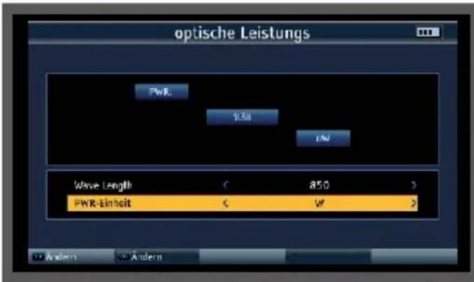
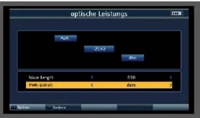
In the Wave Lenght field, select the wavelength at which the measurement is to be carried out. The following wavelengths are available: 850nm, 1270nm, 1300nm, 1310nm, 1130nm, 1490nm, 1550nm, 1625nm
If necessary, change the unit in which you want to measure in the lower PWR unit field.
10. TECHNICAL DATA
| HF PART | |
| Frequency range DVB-C/-T/T2, DAB+, TV, FM 48-862MHz | |
| Frequency range | DVB-S/- |
| S2950-2150 MHz | |
| TV standardsB/G, I, D/K, M, N | |
| Standards | DVB-S/S2x/T/T2/C, MPEG-2, H.264/AVC,H265/HEVC (10 bit) |
| SAT RECEIVER | |
| Input level range-65 to -25 dBm | |
| Control signal 22 Khz, DiSEqCTM 1.2, SCR | Single-cable system |
| LNB power supply13V/18V, I max. 400mA | |
| Demouldulation type | QPSK, 8PSK, 16APSK |
| Symbol rate (MS/s) | 1-45 (DVB-S), 2-45 (DVB-S2) |
| DVB-T/T2 RECEIVER | |
| DVB-T modulation method | QPSK, 16/64 QAM |
| Modulation method DVB-T2QPSK, 16/64/256 QAM Input | |
| level range -79.5dBm (max) | |
| Power supply antenna5V, 12V, 24V Imax 100mA | |
| DVB-C RECEIVER | |
| Channel bandwidth MHz6, 7, 8 | |
| Modulation method DVB-C 16/32/64/128/256QAM | |
| Input symbol rate MS/s 2-6999 | |
10. TECHNICAL DATA
| OPTICAL RECEIVER | |
| Wavelengths nm 850-1550 | |
| +6 | Input level rangedBm -40 to |
Measuring accuracydBm ± 2
| LCD DISPLAY | |
| LCD type | TFT |
| Pixel480x3 (RGB) | |
Visible image size154 .08 x 85.92mm
| TV SYSTEM | |
| Color standards | PAL, SECAM, NTSC |
| AudioFM, NICAM and AM audio, AAC/ | HEAAC, Dolby AC3 |
| AUDIO/VIDEO PROCESSING | |
| Video decompressionMPEG-2 MP@HI, | MPEG-1 DecodirqMPEG4 ASP@L5 HD Resolution, H.264, MP&HP@L4,HW JPEG decoding, HEVC/H.265(10 bit) |
| Replay frequency | PAL-25 Frame@720*576 NTSC-30 Frame@720*480 |
| Video Format4 :3, 16:9,By Pan & Scan and Letter Box | |
| Conversion | |
| Audio decompression | MPEG-1 Layer 1/11, M.PEG-2 Laye, 1/11 |
| Audio outputStereo , mono, R/L | |
10. TECHNICAL DATA
| POWER SUPPLY | |
| Lithium/ion5 Ah, 7.4V | |
| DC-External12V/ 1.5A | |
| CONNECTIONS | |
| HF input | Sat75 |
| RF input DVB-T/T2 / | DVB-C |
| AV IN3 .5 mm jack Audio stereo/video | |
| AV OUT3 .5 mm jack audio stereo/video | |
| TV output | HDMI 1.3a |
| TV input | HDMI 1.3a |
| USB connection | USB 2.0 |
| LAN interface | RJ 45 |
| DC supply12 V hollow plug socket | |
| OPTICAL INPUT | |
| Input FC,ST,LC | |
| Wavelength 850,1270,1300,1310,1330,1490,1550 | 1625 (nm) |
| Input level range dBm-70~6 | |
HF frequency range850~1700 (nm)
| DIMENSIONS AND WEIGHT |
| Dimensions (W × H × D) mm346*299*100 mm |
| Weight kg 3.1 Kg |


| TECHNICAL DATA POWER SUPPLY UNIT | |
| manufacturer | YUNSHENG PLASTIC ELECTRONIC CO.,LTD |
| Model number YS03A-120150U | |
| Input voltage 100-230VAC | |
| Input frequency 50-60Hz | |
| Output voltage 12VDC | |
| Output current 1.5A | |
| Output power 18W | |
| Average efficiency in operation 84,6% | |
| Efficiency at low load (10%) 84,6% | |
| Power consumption at no load ≤0.1W | |
11. DISPOSAL NOTE
11.1 Disposal of the packaging
The packaging of your device consists exclusively of recyclable materials. Please sort them accordingly and return them to the "Dual System".
11.2 Disposal of the appliance

The symbol of a crossed-out wheeled garbage can shown on the right indicates that this appliance is subject to Directive 2012 / 19 / EU. This directive states that you must not dispose of this appliance with normal household waste at the end of its useful life,
but must be handed in at specially equipped collection points, recycling centers or waste disposal companies. This disposal is free of charge for you. Protect the environment and dispose of it properly. For more information, please contact your local waste disposal company or the city or municipal administration.
11.3 Disposal of batteries

Batteries and rechargeable batteries must not be disposed of with household waste. The symbol shown on the right means that you are obligated as a consumer, dispose of all batteries and rechargeable batteries separately. Appropriate collection containers are available from specialist retailers and numerous public
facilities. Information on the disposal of old batteries and rechargeable batteries can also be obtained from specialist disposal companies, municipal and local authorities. This disposal is free of charge for you. Protect the environment and dispose of it properly.
CE

Your appliance bears the CE mark and complies with all required EU standards.
Hereby, TELESTAR DIGITAL GmbH confirms the conformity of the TELESTAR SATPLUS 4 device with the essential protection requirements of the Radio Equipment Directive 2014/53/EU
V (RED - Radio Equipment Devices), the RoHS Directive (2011/65/EU), the REACH Regulation 1907/2006 and the ErP Directive (2009/125/EU). The declaration of conformity for this product can be found at: www.telestar.de/de_DE/Konformitaetserklaerung/352-529/?productID=24843.

TELESTAR
SATPLUS 4
Mode d'emploi

Sous reserve de modifications.
6.3 Spectre DVB-S/S2
Resolution, H.264, MP&HP@L4,HW
JPEG deooding,
HEVC/H.265(10 bits)
NO. BESCHRIJVING FUNC TIE
m = 311
waarde.
MER-meting (Modulation Error Rate)
Carrier-to-noise, Carrier-to-noise ratio
MER-meting (Modulation Error Rate)
Carrier-to-noise, Carrier-to-noise ratio
resolute, H.264, MP&HP@L4,HW
JPEG decoding,
HEVC/H.265(10 bit)
Herhalingsfrequentie
PAL-25 Frame@720*576
NTSC-30 Frame@720*480
m = 311
valore.
6. SAT-CAMPO DI MISURA
AudioFM, NICAM e AM, AAC/
HEAAC, Dolby AC3