
LPAD 12CX - Mixer RCF - Free user manual and instructions
Find the device manual for free LPAD 12CX RCF in PDF.

| Product type | Analog mixing console |
| Brand | RCF |
| Model | LPAD 12CX |
| Dimensions (W x D x H) | 480 x 340 x 100 mm |
| Weight | 3.85 kg |
| Power supply | 100-240 V ~ 50/60 Hz, 40 W |
| Microphone/line inputs | 6 XLR/6.35 mm jack inputs (channels 1-4 mic/line, 5-6 and 7-8 stereo mic/line) |
| Stereo line inputs | 2 x 6.35 mm jack inputs (channels 9-10 and 11-12) + 2 x RCA inputs (9-10 and 11-12) |
| 2TK input | 1 x RCA input |
| Stereo return | 1 x 6.35 mm jack input |
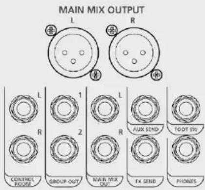
| Main outputs | MAIN MIX output on balanced XLR and 6.35 mm jack |
| Additional outputs | CONTROL ROOM output 6.35 mm jack, PHONES output 6.35 mm jack, GROUP OUT output 6.35 mm jack, AUX SEND output 6.35 mm jack, FX SEND output 6.35 mm jack |
| Equalizer | 3-band (HI, MID, LOW) on mono channels; 2-band (HI, LOW) on stereo channels 9-10 and 11-12 |
| Compressors | 4 compressors on channels 1-4 |
| Internal effects | 99 preset effects (Echo, Echo+Verb, Tremolo, Plate, Chorus, Vocal, Rotary, Small Room, Flange+Verb, Large Hall) with 10 variations each |
| Phantom power | +48 V switchable for channels 1-6 |
| Low-cut filter | LOW CUT at 75 Hz, 12 dB/octave |
| Footswitch connector | 6.35 mm jack for FX MUTE control |
| Optional card slot | For MP3 player card, MP3 player/recorder card (USB up to 32 GB) or Bluetooth card |
| Mounting accessories | Rack mounting brackets (ref. 133 60 292) |
| Cleaning | Use a dry cloth, avoid solvents, alcohol, benzene |
| Protection class | Class I (grounded) |
Frequently Asked Questions - LPAD 12CX RCF
User questions about LPAD 12CX RCF
0 question about this device. Answer the ones you know or ask your own.
Ask a new question about this device
Download the instructions for your Mixer in PDF format for free! Find your manual LPAD 12CX - RCF and take your electronic device back in hand. On this page are published all the documents necessary for the use of your device. LPAD 12CX by RCF.
USER MANUAL LPAD 12CX RCF
- Read all precautions, in particular those related to safety, very carefully as they provide important information.
WARNING: to prevent the risk of fire or electric shock, never expose this product to rain or humidity.

2. POWER SUPPLY FROM MAINS
a. The mains voltage is sufficiently high to cause electrocution; install and connect the device before plugging it in.
b. Before powering up, make sure that all the connections have been made correctly and the voltage of your mains corresponds to the voltage shown on the rating plate on the unit. Contact your RCF dealer if it does not.
c. The metallic parts of the unit are earthed through the power cable. The device is a CLASS I apparatus and must be plugged into an earthed socket.
d. Protect the power cable from damage; make sure it is positioned in a way that it cannot be stepped on or crushed by objects.
e. To prevent the risk of electric shock, never open this product: there are no parts inside that the user needs to access.
- Make sure that no objects or liquids get into the device, as this may cause a short circuit.
The device must not be exposed to drips or splashes. Do not place objects filled with liquid, such as vases, on the device. Do not place naked flames (such as lighted candles) on the device.
- Never attempt to carry out any operations, modifications or repairs that are not expressly described in this manual.
Contact your authorized service centre or qualified personnel should any of the following occur:
- The device does not work (or works anomalously).
- The power cable has been damaged.
- Objects or liquids have got into the device.
-
The device has been subject to a heavy shock.
-
Unplug the device if it will not be used for a long time.
-
Switch the device off immediately and unplug it if emission of strange odours or smoke is noticed.
-
Do not connect the device to any equipment or accessories other than those provided for the purpose.
For suspended installation, only use the dedicated anchoring points. Do not try to hang the device using unsuitable elements or elements which are not specific for this purpose. Also check the suitability of the support surface to which the product is anchored (wall, ceiling, structure, etc.), and the components used for attachment (screw anchors, screws, brackets not supplied by RCF etc.), which must guarantee the security of the system / installation over time, also considering, for example, the mechanical vibrations normally generated by transducers.
To prevent the risk of falling, do not stack multiple units of the device unless this possibility is specified in the user manual.
- RCF S.p.A. strongly recommends this product is only installed by professional qualified installers (or specialised firms) who can ensure correct installation and certify it according to the regulations in force.
The entire audio system must comply with the current standards and regulations regarding electrical systems.

9. Supports and trolleys
The equipment should be only used on trolleys or supports of the type recommended by the manufacturer, where necessary. The equipment / support / trolley assembly must be moved with extreme caution. Sudden stops, excessive pushing force and uneven floors may cause the assembly to overturn.
- Numerous mechanical and electrical factors must be considered when installing a professional audio system (in addition to strictly acoustic factors, such as sound pressure, coverage angles, frequency response etc.).
11. Hearing loss
Exposure to high sound levels can cause permanent hearing loss. The sound pressure level which causes hearing loss is different from person to person and depends on the exposure time. Adequate protection devices must be used to prevent potentially dangerous exposure to high sound pressure levels. Ear plugs or protective ear muffs must be worn when a transducer capable of producing high sound levels is used. See the technical specifications in the manual for the maximum sound pressure level.
IMPORTANT NOTES
- To prevent the occurrence of noise on line signal cables, use screened cables only and avoid putting them close to:
- Equipment generating high-intensity electromagnetic fields
- Power cables
- Speaker lines

OPERATING PRECAUTIONS
- Place the device away from sources of heat and always ensure an adequate air circulation around it.
- Do not overload this product for a long time.
- Never force the controls (buttons, knobs etc.).
- Do not use solvents, alcohol, benzene or other volatile substances for cleaning the external parts of the device.
IMPORTANT NOTES
Please read this instruction manual carefully and keep it on hand for future reference before connecting and using the device. The manual is an integral part of the device and must accompany it when it changes ownership as a reference for correct installation and use as well as for the safety precautions. RCF S.p.A. will not assume any responsibility for the incorrect installation and/or use of the device.

IMPORTANT NOTES
INFORMATION ON THE DEVICE
Thank you for purchasing a RCF mixing console.
L-PAD 12CX is a versatile audio mixer equipped with all the tools needed for appropriately processing multiple audio signals from a variety of sources. The features can be expanded by adding optional cards to implement MP3 audio player/recorder or Bluetooth functions.
CLEAR SOUND
RCF mixing consoles devices combine RCF's professional "sound culture" heritage with innovative design and dedicated manufacturing. RCF mixing consoles secure clear sound, accurate sound dynamics and extreme versatility of use by passionate professional users. RCF mixing consoles are designed to combine perfectly with RCF active speakers.
RELIABILITY
All RCF mixing consoles undergo four extensive instrumental quality tests during construction. A listening test is carried out at the end of production followed by a final quality control inspection to locate any appearance defects, such as scratches or dents. The process guarantees outstanding reliability and makes sure that the device you have purchased is of the highest quality.
DESIGN
The unique design of RCF mixing consoles is an expression of typically Italian RCF creativity. RCF mixing consoles combine modern, excellent ergonomic design. In addition to their striking appearance, the original side profile of the mixers makes them easy to grasp securely.
FEATURES
Inputs 6 MIC XLR/line inputs with 14 inch jack (1, 2, 3, 4 mono lines with 5-6, 7-8 stereo line inserts)
4 compressors (Ch. 1 - 4)
2 stereo line inputs with ¼ inch jack (3-4, 5-6)
2 stereo line inputs with 14 inch jack or RCA
1 2TK input with RCA
1 stereo return with 14 inch jack
Outputs 1 2TK output with RCA
1 MAIN MIX stereo output with balanced XLR and 14 inch jack
1 CONTROL ROOM stereo output with 14 inch jack
1 PHONES stereo output with 14 inch jack
1 AUX SEND outputs with 14 inch jack
1 FX SEND output with 14 inch jack
Other features 1 footswitch connector with 14 inch jack for FX MUTE
Three-band EQ on mono channels
Dual-band EQ on stereo channels 9-10, 11-12
1 AUX SEND
1 FX SEND
Internal digital effects: 99 preset effects, including Echo, Echo+Verb, Tremolo, Plate, Chorus, Vocal, Rotary, Small Room, Flange+Verb, Large Hall.
Optional card slot: MP3 player card, MP3 player/recorder card (with USB 1.1 port for USB flash drive up to 32 GB), Bluetoothconnection card
Internal PSU 100 V-240 V, 50-60 Hz, 40 W
Physical specifications Dimensions: L = 480 mm, W = 340 mm, H = 100 mm
Weight: 3.850 kg
FUNCTIONS
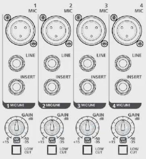
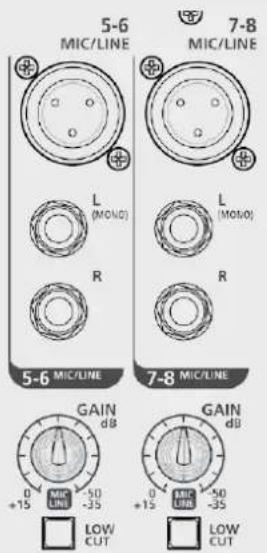
MIC input (Ch. 1 - Ch. 7/8) Connect your microphones to these balanced XLR connectors: pin1=Earth, pin2=Hot, pin3=Cold. These inputs are provided with +48 V phantom power for condenser or electret microphones. Gain scale 0 dB/-50 dB.
LINE input (Ch. 1 - Ch. 4) Connect your line level devices to these TRS jack connectors: tip=Hot, ring=Cold, sleeve=Earth. These inputs are suitable for external pre-amplifier and DI-boxes. Gain scale +15 dB/-35 dB.
INSERT (Ch. 1 - Ch. 4) These TRS connectors: tip=send, ring=return, sleeve=common earth allow to send the signal, thru an unbalanced line, to external devices (i.e. compressor) and return the processed signal back into the channel.
GAIN (Ch. 1 - Ch. 6) This controls the level gain (0 dB/-50 dB for microphone input and +15 dB/-35 dB for line input when in use).
LOW CUT switch: Press this button to cut off frequency below 75 Hz with a slope of 12 dB/oct. This is useful to prevent rumbling when using microphones.
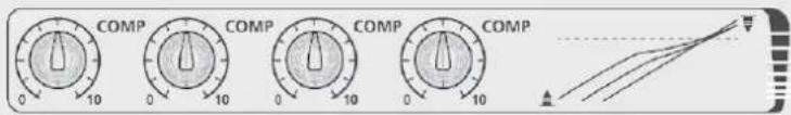
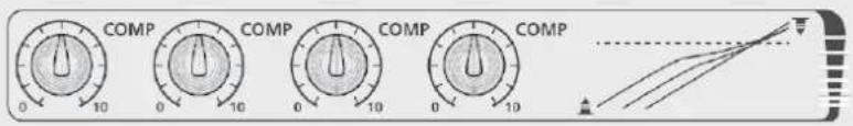
COMP (Ch. 1 - Ch. 4). A single potentiometer controls both compressor threshold and ratio.

STEREO LINE INPUT
(Ch. 5/6 - Ch. 11/12)
Plug in your keyboard, line level or stereo devices here. Gain scale +15 dB/-35 dB (Ch. 5/6 - Ch. 7/8). The corresponding channel works as a mono channel when MIC input 5-6 or 7-8 is used.
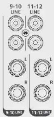
RCA LINE INPUT
(Ch. 9/10 - Ch. 11/12) Plug in your low-level or consumer devices, like CD players, computers or mobile phones here (adapter needed).
STEREO RETURN
Connect signals from external devices, such as FX modules, to these unbalanced TRS jacks.
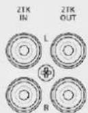
2TK IN - 2TK OUT
These unbalanced RCA connectors are suitable for connecting audio player and recorder devices.
FUNCTIONS
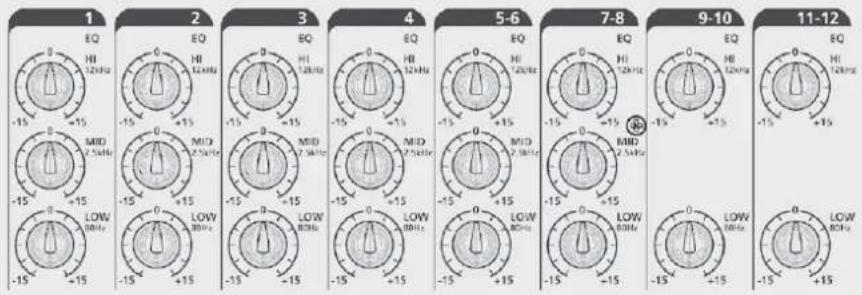
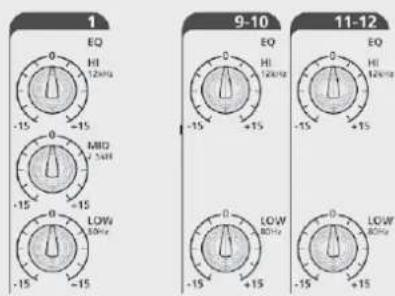
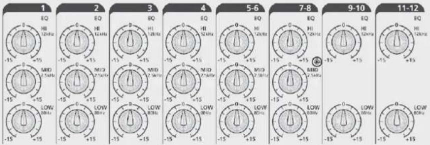
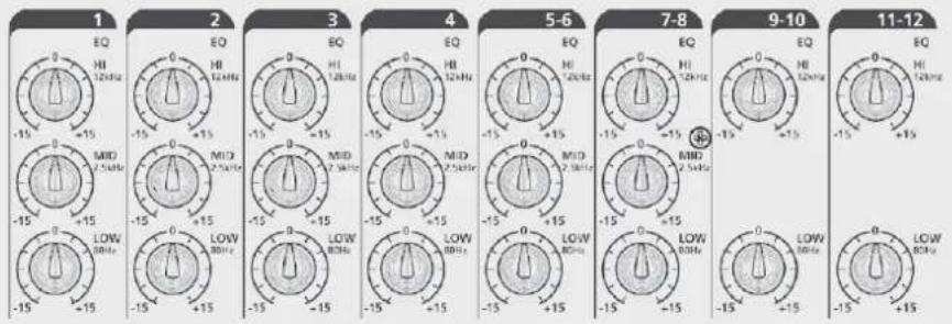
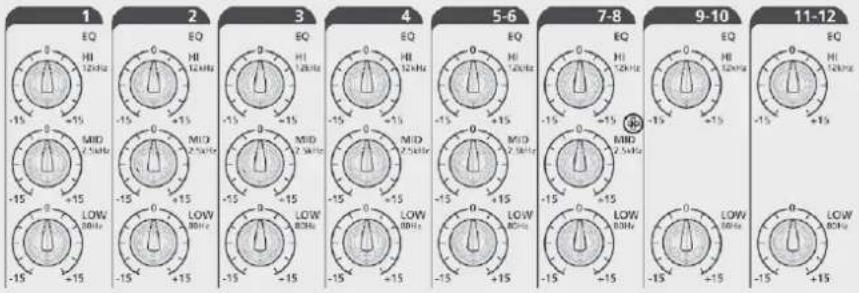
EQ
A three-band EQ is available for mono channels:
HI = ±15 dB@12 kHz
MID = ±15 dB@2.5 kHz
LOW = ±15 dB@80 Hz
Dual-band EQ for stereo channels:
HI = ±15 dB@12 kHz
LOW = ±15 dB@80 Hz
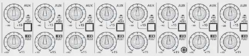
AUX: It is an auxiliary send, level - to +15 dB. The signal is routed to the AUX SEND output jack. The POST/PRE function determines whether to extract the signal after the fader position or independently from it.
PRE/POST button: When released, the signal is extracted in pre-fader position (independently from the fader level); when pressed, the signal is extracted from post-fader position (the send level depends on the fader level).
FX SEND: This potentiometer sends the signal to the internal effects device. The signal is also routed to the FX output jack. The signal is extracted in post-fader position.
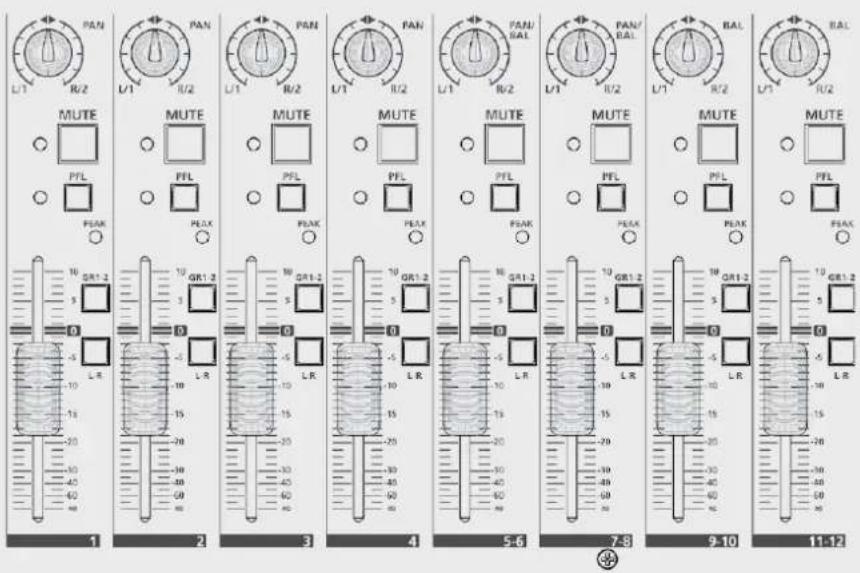
PAN or PAN/BAL: This control defines the signal stereo imaging for mono channels or left-right balance for stereo channels.
MUTE button: Press this button (red LED on) to mute the channel.
PFL button: Press this button to listen the signal through the PHONES output even if the fader is in -∞ position or muted. This function is useful to check the channel input level (see the OUTPUT LEVEL meter).
GROUP 1-2 button: Press this button to route the channel signal to the group 1-2 audio output. In this case, the PAN/BAL position control defines the quantity of signal routed to GROUP 1 or GROUP 2.
L-R button: Press this button to route the channel signal to the MAIN MIX output.
FADERS Ch. 1 - Ch. 4:
MONO Channels level control
FADERS Ch. 5/6 - Ch. 7/8:
MONO/STEREO channels level control
FADERS Ch. 9/10 - Ch. 11/12:
STEREO channels level control
FUNCTIONS
MAIN MIX output: XLR balanced male connectors. Plug in your active speakers or main sound reinforcement system amplifier (for passive speakers) of here. The output level is +4 dBu. This output is repeated on the TRS jack.
CONTROL ROOM output: Plug your studio monitor or local speakers into these TRS jacks.
GROUP OUT output: TRS jacks. Plug in the lines to be routed to locations or devices other than MAIN here.
AUX SEND output: Plug a wedge stage monitor or external FX device into this TRS jack. The processed signal from the FX device is returned to the mixer via the Stereo Return jacks.
FX SEND output: The signal going to the Internal FX is replicated in this TRS Jack for different application. If the internal FX device is not used, FX SEND can be used as second AUX SEND for connecting a further wedge monitor.
PHONES: TRS stereo jack, Tip = Left, Ring = Right, Sleeve = Common Earth. Plug in your headphones here to listen to MAIN MIX or PFL when pressed.
FOOTSWITCH: TS connector, Tip = FX, Sleeve = EARTH. Connect a footswitch here. Press once to bypass the FX, press again to resume the FX. The same function is available for the FX MUTE button.
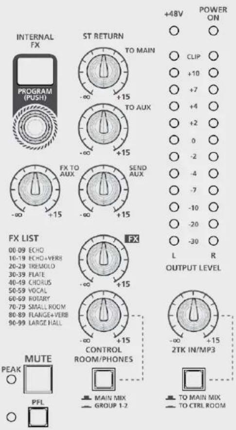
OUTPUT LEVEL: These LEDs show the MAIN MIX OUTPUT level.
Keep under CLIP level to prevent generating distorted sounds or dangerous sound levels.
ST RETURN control: This defines the STEREO RETURN input signal level routed to MAIN MIX output.
TO AUX control: This defines the signal STEREO RETURN input level routed to AUX1 output.
SEND AUX control: This is the AUX SEND master level control.
FX control: This is the FX SEND master level control.
CONTROL ROOM/PHONES control: This defines the signal level routed to CONTROL ROOM output and PHONES output.
MAIN MIX-GROUP 1-2 switch: In upper position allows you to listen the MAIN MIX through the CONTROL ROOM speakers. When pressed, it allows to listen to GROUP 1-2 via the CONTROL ROOM speakers.
2TK IN/MP3 control: This defines the signal level from the 2TK IN input or from optional cards (such as the RCF mixing consoles player, recorder or Bluetooth cards) routed to MAIN MIX output.
TO MAIN MIX/TO CONTROL ROOM switch: Defines where to route the signal coming from 2TK IN or optional cards: to MAIN MIX when in upper position, to CONTROL ROOM when pressed (lower position).
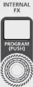
INTERNAL FX PROGRAM selector: This encoder can be used to select one of the 100 effects available on the internal DSP. Press the encoder to confirm the selection. See the FX LIST to select the required effect.
FX TO AUX control: This defines the signal level of the internal FX return routed to the AUX.
FADER GROUP 1-2: GROUP 1-2 signal level control. The GROUP 1-2 signal is routed to the MAIN MIX when the L-R button is pressed.
FADER MAIN MIX: MAIN MIX output level control.
- Turn your RCF Mixing Console on.
- Set all the faders and controls to minimum position (0 or -∞)
- Plug a microphone into the XLR connector - MIC input of channel 1.
- Connect your speaker system to the MAIN MIX output and turn it on.
- Press the PFL button. Sing into the microphone and adjust the GAIN control until the OUTPUT LEVEL is shown by means of LEDs (all green LEDs should light up and the first yellow LED should do so occasionally).
- Press again the PFL button to cancel the operation.
- Adjust the FADER up to "0" position.
- Check whether the MUTE button is in released (UN-MUTED channel).
- Press the L-R button to route the channel signal to MAIN MIX.
- Carefully turn up the MAIN MIX fader to reach a reasonable sound level.
- Enjoy the quality of your RCF mixing console.
natural_image
Front view of a device chassis with labeled ports and an arrow pointing to a control panel (no text or symbols present)
flowchart
graph LR
    A["Speaker"] --> B["1 MIC"]
    B --> C["LINE"]
    C --> D["INSERT"]
    D --> E["1 METER"]
    E --> F["LOW CUT"]
    G["MUTE"] --> H["10000000000000000000000000000000000000000000000000000000000000000000000000000000000000000000000000000"] --> I["15 15 35"]
    J["MAIN MIX OUTPUT"] --> K["15 15 35"]
    L["+46V POWER OPB"] --> M["+18 P"]
    M --> N["+19 P"]
    N --> O["+2 P"]
    O --> P["+3 P"]
    P --> Q["+2 P"]
    Q --> R["+2 P"]
    R --> S["+2 P"]
    S --> T["+2 P"]
    T --> U["+2 P"]
    U --> V["+2 P"]
    V --> W["+2 P"]
    W --> X["+2 P"]
    X --> Y["+2 P"]
    Y --> Z["+2 P"]
    Z --> AA["+2 P"]
    AA --> AB["+2 P"]
    AB --> AC["+2 P"]
    AC --> AD["+2 P"]
    AD --> AE["+2 P"]
    AE --> AF["+2 P"]
    AF --> AG["+2 P"]
    AG --> AH["+2 P"]
    AH --> AI["+2 P"]
    AI --> AJ["+2 P"]
    AJ --> AK["+2 P"]
    AK --> AL["+2 P"]
    AL --> AM["+2 P"]
    AM --> AN["+2 P"]
    AN --> AO["+2 P"]
    AO --> AP["+2 P"]
    AP --> AQ["+2 P"]
    AQ --> AR["+2 P"]
    AR --> AS["+2 P"]
    AS --> AT["+2 P"]
    AT --> AU["+2 P"]
    AU --> AV["+2 P"]
    AV --> AW["+2 P"]
    AW --> AX["+2 P"]
    AX --> AY["+2 P"]
    AY --> AZ["+2 P"]
    AZ --> BA["+2 P"]
    BA --> BB["+2 P"]
    BB --> BC["+2 P"]
    BC --> BD["+2 P"]
    BD --> BE["+2 P"]
    BE --> BF["+2 P"]
    BF --> BG["+2 P"]
    BG --> BH["+2 P"]
    BH --> BI["+2 P"]
    BI --> BJ["+2 P"]
    BJ --> BK["+2 P"]
    BK --> BL["+2 P"]
    BL --> BM["+2 P"]
    BM --> BN["+2 P"]
    BN --> BO["+2 P"]
    BO --> BP["+2 P"]
    BP --> BQ["+2 P"]
    BQ --> BR["+2 P"]
    BR --> BS["+2 P"]
    BS --> BT["+2 P"]
    BT --> BU["+2 P"]
    BU --> BV["+2 P"]
    BV --> BW["+2 P"]
    BW --> BX["+2 P"]
    BX --> BY["+2 P"]
    BY --> BZ["+2 P"]
    BZ --> CA["+2 P"]
    CA --> CB["+2 P"]
    CB --> CC["+2 P"]
    CC --> CD["+2 P"]
    CD --> CE["+2 P"]
    CE --> CF["+2 P"]
    CF --> CG["+2 P"]
    CG --> CH["+2 P"]
    CH --> CI["+2 P"]
    CI --> CJ["+2 P"]
    CJ --> CK["+2 P"]
    CK --> CL["+2 P"]
    CL --> CM["+2 P"]
    CM --> CN["+2 P"]
    CN --> CO["+2 P"]
    CO --> CP["+2 P"]
    CP --> CQ["+2 P"]
    CQ --> CR["+2 P"]
    CR --> CS["+2 P"]
    CS --> CT["+2 P"]
    CT --> CU["+2 P"]
    CU --> CV["+2 P"]
    CV --> CW["+2 P"]
    CW --> CX["+2 P"]
    CX --> CY["+2 P"]
    CY --> CZ["+2 P"]
    CZ --> DA["+2 P"]
    DA --> DB["+2 P"]
    DB --> DC["+2 P"]
    DC --> DD["+2 P"]
    DD --> DE["+2 P"]
    DE --> DF["+2 P"]
    DF --> DG["+2 P"]
    DG --> DH["+2 P"]
    DH --> DI["+2 P"]
HOW TO IMPROVE THE SOUND
The RCF mixing console implements several powerful tools to improve the sound quality of your music even more.
COMP: Turn the COMP control clockwise to add a compression effect to the signal. This allows to control the dynamic of the signal, limiting peaks and gaining level in case of low signals.
EQ: A three-band EQ is available on each mono channel, while a dual-band EQ is available on stereo channels 9-10 and 11-12. Adjust these parameters to subtract noise frequencies or magnify desired sounds.
FUNCTIONS
INTERNAL FX: Keep singing in the microphone, turn clockwise the yellow FX send until the red led PEAK/MUTE lights occasionally.
Turn the INTERNAL FX PROGRAM encoder and press it to confirm the selection of the required FX (see the FX LIST below).
Set the FX knob to 12 o'clock position (the rightmost yellow knob). Now, turn the FX RETURN fader up carefully. Stop at the required level.
Ten effect algorithms are available with ten variations each:
ECHO: Ideal for delay effects. Use for vocals and brass.
ECHO+VERB: Deeper and more sophisticated effect than ECHO preset. It adds a reverb effect to delay rebounds.
TREMOLO: Ideal guitar effect.
PLATE: Recommended for snare drums or percussions, like congas or timbales.
CHORUS: Try it on acoustic guitar or to create a deeper stereo effect on background vocal.
VOCAL: Ideal for adding depth and intensity to leading vocals or solo instruments.
ROTARY: Great for Hammond organs or Rhodes Pianos.
SMALL ROOM: Try it over small percussions like castanet or claves.
FLANGE+VERB: Great for electric guitar to obtain particular effects.
LARGE HALL: Good for voices, electric guitar and main instruments, especially for ballads.
FX LIST
00-09 ECHO
10-19 ECHO+VERB
20-29 TREMOLO
30-39 PLATE
40-49 CHORUS
50-59 VOCAL
60-69 ROTARY
70-79 SMALL ROOM
80-89 FLANGE+VERB
90-99 LARGE HALL
AVAILABLE ACCESSORIES
RCF MIXING CONSOLES PLAYER CARD: USB stick based MP3 Player Card – Max. capacity: 32 GB (Part Number: 133 60 287).
RCF MIXING CONSOLES RECORDER CARD: USB flash drive based MP3 player/recorder card - Max. capacity: 32 GB (Part Number: 133 60 288).
RCF MIXING CONSOLES BLUETOOTH CARD: Bluetooth connection card. This card allows to play your music playlist from Smartphone, Tablet or any Bluetooth device. (Part Number: 133 60 289)
MOUNT ACCESSORIES
Rack ears (RCF Part Number: 133 60 292)
OPTIONAL CARDS
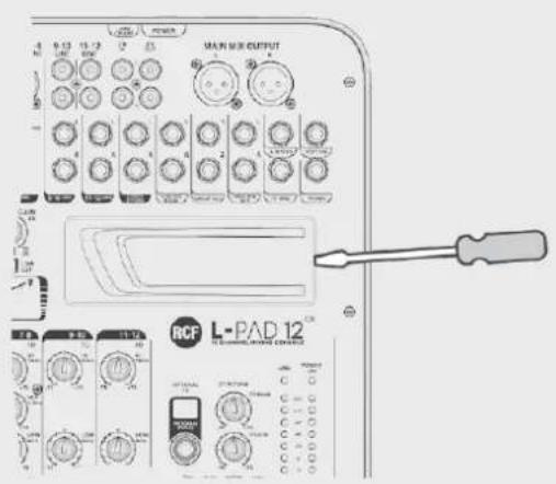
INSTALLATION AND USE
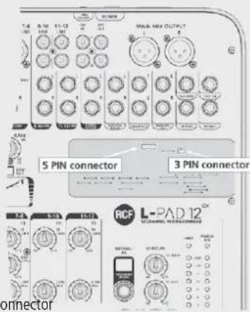
With the help of a small flat screwdriver press horizontally the plastic cover on its right side and remove it carefully.
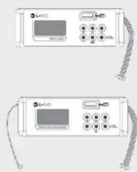
To install a RCF Mixing Consoles Bluetooth card or a RCF Mixing Consoles player card, plug the 5 pin cable into the 5 pin connector on the PCB board as shown.
To install a RCF Mixing Consoles player/recorder card, plug the 5 pin cable into the 5 pin connector and the 3 pin cable into the 3 pin connector on the PCB board as shown.
Now place the optional card in its site and enjoy the new functions.
RCF MIXING CONSOLES BLUETOOTH CARD
Turn the Bluetooth interface on your mobile device on and press the PAIR button on the card. Your mobile device will recognize the "BT2.1" Bluetooth device. Pair your device with the BT2.1 device. You can now play your favourite music.
Turn clockwise the knob named 2TK/MP3 up to 12 o'clock position and check if the TO MAIN MIX/TO CTRL ROOM switch is in upper position; now raise carefully the MAIN MIX fader up to the desired listening level. You can adjust the volume on the card panel also pressing the buttons VOL+ and VOL-.
RCF MIXING CONSOLES PLAYER CARD
From your computer, copy in a USB drive as many mp3 files as you want, even contained in folders (max 32 GB total), insert the USB pen in the USB dedicated connector on the card, press and hold the PUSH&HOLD button for two seconds, the card will start to play the first file of the first folder, the display will show alternatively the number of the file and the number of the folder which is playing. Press the "◀" or "▶" button to skip to the previous or to the following track. Hold the same buttons pressed to change the selected folder. Use the PLAY/PAUSE button to pause or restart playback. Press STOP to stop playback. Press the loop button (⇨) repeatedly to select random play, loop the current track or loop the entire programme, respectively. Turn clockwise the knob named 2TK/MP3 up to 12 o'clock position and check if the TO MAIN MIX/TO CTRL ROOM switch is in upper position; now raise carefully the MAIN MIX fader up to the desired listening level.
From your computer, copy in a USB drive as many mp3 files as you want, even contained in folders (max 32 GB total). Insert the USB flash drive in the dedicated USB port on the card, press and hold the PUSH & HOLD button pressed for two seconds. The card will start playing the first file in the first folder. The file number and folder number which is playing will be shown on the display. Press the "◀" or "▶" buttons to skip to the previous or to the following music file. Hold the same buttons pressed to change the selected folder. The card allows you to record the program present on MAIN MIX: press the REC button once, now the board is in "rec ready status" and the display shows a flashing REC advise; press REC again to start recording; press PUSH&HOLD button once for stop recording; the card will create a new folder on the USB pen called FrE01 where the created files will find place. Use the PLAY/PAUSE button to pause or restart playback. Press the loop button (⇨) repeatedly to select random play, loop the current track or loop the entire programme, respectively.
Turn clockwise the knob named 2TK/MP3 up to 12 o'clock position and check if the TO MAIN MIX/TO CTRL ROOM switch is in upper position; now raise carefully the MAIN MIX fader up to the desired listening level.
Gently remove the plastic cover with the help of a screwdriver.
Be sure to connect
each connector in its proper position.
natural_image
Two identical electronic device back panels with cables and ports, no visible text or symbols5 pin connector3 pin connector
AVVERTENZE PER LA SICUREZZA
Small Room, Flange+Verb, Large Hall.
HI = ±15 dB a 12 kHz
LOW = ±15 dB a 80 Hz
FUNZIONI
natural_image
Front view of a control panel with buttons and indicator lights (no text or symbols visible)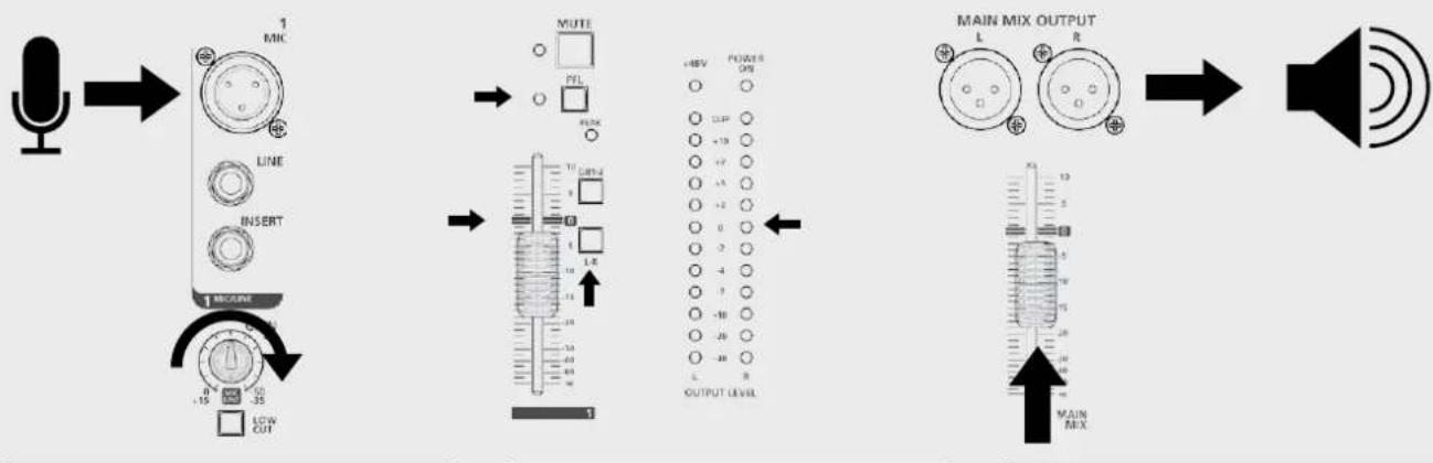
flowchart
graph LR
    A["Speaker"] --> B["1 MICR"]
    B --> C["MUTE"]
    C --> D["MAIN MIX OUTPUT"]
    D --> E["Speaker"]

    subgraph Signal Process
        B1["LINE"] --> B2["LIN"]
        B3["INSERT"] --> B4["LIN"]
        B5["1 MICR"] --> B6["LIN"]
        B7["LIN"] --> B8["LIN"]
        B9["LIN"] --> B10["LIN"]
        B11["LIN"] --> B12["LIN"]
        B13["LIN"] --> B14["LIN"]
        B15["LIN"] --> B16["LIN"]
        B17["LIN"] --> B18["LIN"]
        B19["LIN"] --> B20["LIN"]
        B21["LIN"] --> B22["LIN"]
        B23["LIN"] --> B24["LIN"]
        B25["LIN"] --> B26["LIN"]
        B27["LIN"] --> B28["LIN"]
        B29["LIN"] --> B30["LIN"]
        B31["LIN"] --> B32["LIN"]
        B33["LIN"] --> B34["LIN"]
        B35["LIN"] --> B36["LIN"]
        B37["LIN"] --> B38["LIN"]
        B39["LIN"] --> B40["LIN"]
        B41["LIN"] --> B42["LIN"]
        B43["LIN"] --> B44["LIN"]
        B45["LIN"] --> B46["LIN"]
        B47["LIN"] --> B48["LIN"]
        B48["LIN"] --> B49["LIN"]
        B50["LIN"] --> B51["LIN"]
        B52["LIN"] --> B53["LIN"]
        B54["LIN"] --> B55["LIN"]
        B56["LIN"] --> B57["LIN"]
        B58["LIN"] --> B59["LIN"]
        B60["LIN"] --> B61["LIN"]
        B62["LIN"] --> B63["LIN"]
        B64["LIN"] --> B65["LIN"]
        B66["LIN"] --> B67["LIN"]
        B68["LIN"] --> B69["LIN"]
        B70["LIN"] --> B71["LIN"]
        B72["LIN"] --> B73["LIN"]
        B74["LIN"] --> B75["LIN"]
        B76["LIN"] --> B77["LIN"]
        B78["LIN"] --> B79["LIN"]
        B80["LIN"] --> B81["LIN"]
        B82["LIN"] --> B83["LIN"]
        B83["LIN"] --> B84["LIN"]
        B84["LIN"] --> B85["LIN"]
        B85["LIN"] --> B86["LIN"]
        B86["LIN"] --> B87["LIN"]
        B87["LIN"] --> B88["LIN"]
        B88["LIN"] --> B89["LIN"]
        B89["LIN"] --> B90["LIN"]
        style A fill:#f9f,stroke:#333
    style E fill:#ccf,stroke:#333
9. Supports et chariots
Large Hall (grand hall), etc.
LOW (graves) = ±15 dB à 80 Hz
LOW (graves) = ±15 dB à 80 Hz
FONCTIONS
natural_image
Front view of a device chassis with labeled ports and an arrow pointing to a control panel (no text or symbols present)
flowchart
graph LR
    A["Speaker"] --> B["1 MIC"]
    B --> C["LINE INSERT"]
    C --> D["1 METER"]
    D --> E["LOW CUT"]
    E --> F["MUTE"]
    F --> G["+40V POWER OFF"]
    G --> H["OUTPUT LEVEL"]
    H --> I["MAIN MIX OUTPUT"]
    I --> J["Speaker"]
COMMENT AMÉLIORER LE SON
ACCESSOIRES DISPONIBLES
Vocal, Rotary, Small Room, Flange+Verb y Large Hall
HI = ±15 dB a 12 kHz
LOW = ±15 dB a 80 Hz
FUNCIONES
CÓMO HACER QUE LA MESA DE MEZCLAS RCF mixing consoles FUNCIONE
natural_image
Diagram of a device rear panel with labeled ports and an arrow pointing to a control panel (no text or symbols present)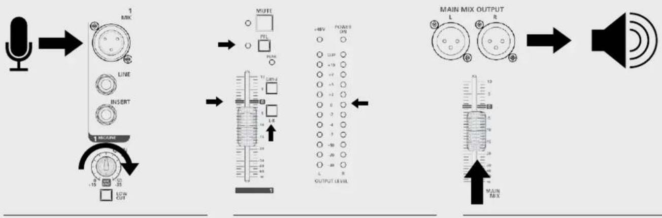
flowchart
graph LR
    A["Speaker"] --> B["1 MIK"]
    B --> C["LINE"]
    C --> D["INSERT"]
    D --> E["1 MODE"]
    E --> F["LOW CUT"]
    F --> G["MUTE"]
    G --> H["OUTPUT LEVEL"]
    H --> I["MAIN MIX OUTPUT"]
    I --> J["Speaker"]
Flange+Verb, Large Hall.
Optionaler Kartenslot: MP3 Player Card, MP3 Player/Recorder Card
FUNKTIONEN
natural_image
Diagram of a device rear panel with labeled ports and an arrow pointing to a control panel (no text or symbols present)
flowchart
graph LR
    A["Speaker"] --> B["1 MIC"]
    B --> C["LINE INSERT"]
    C --> D["1 METER"]
    D --> E["LOW CUT"]
    B --> F["MUTE PFL"]
    F --> G["10 GHz"]
    G --> H["1 L R"]
    H --> I["3"]
    I --> J["+REV POWER OPB"]
    J --> K["100"]
    K --> L["-10"]
    L --> M["-7"]
    M --> N["-5"]
    N --> O["-2"]
    O --> P["0"]
    P --> Q["2"]
    Q --> R["-4"]
    R --> S["-7"]
    S --> T["-10"]
    T --> U["-20"]
    U --> V["-8"]
    V --> W["OUTPUT LEVEL"]
    W --> X["MAIN MIX OUTPUT"]
    X --> Y["Speaker"]
SO KÖNNEN SIE DEN SOUND VERBESSERN
natural_image
Two identical electronic device back panels with cables and connectors, no visible text or symbols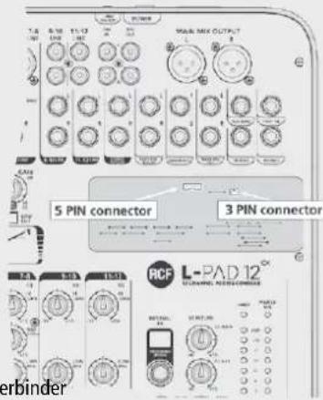
5-Pin-Verbinder3-Pin-Verbinder
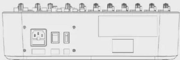
REAR PANEL / PANNELLO POSTERIORE / PANNEAU ARRIÈRE / PANEL TRASERO / GERÄTERÜCKSEITE
natural_image
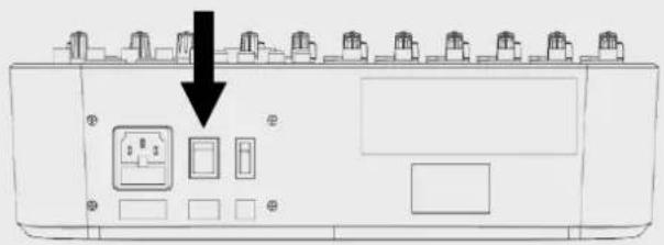
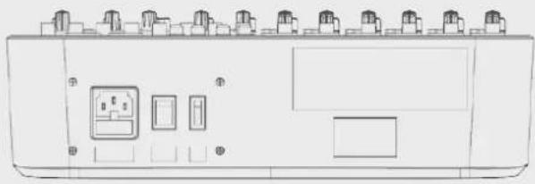
Line drawing of a device rear panel with multiple ports and control buttons (no text or symbols)VDE AC IN SOCKET AC VDE socket to connect the mixer to AC power supply.
ON-OFF SWITCH Switches the mixer on and off
+48 V PHANTOM POWER SWITCH Switches the microphone input +48 V phantom power on and off (Ch. 1 - Ch. 6). Turn the +48 V phantom power on only when using a condenser or electret microphone.
natural_image
Front view of a device control panel with buttons and indicator lights (no text or symbols visible)natural_image
Line drawing of a device front panel with buttons and indicator lights (no text or symbols)natural_image
Line drawing of an industrial control panel with multiple switches and buttons (no text or symbols)natural_image
Front view diagram of a device rear panel with switches and buttons (no text or labels)20 Hz to 22 kHz,+/-1 dB
<0.03% @ +0 dB, 22 Hz\~22 kHz A-weighted
0 dB to -50 dB
+15 dB (balanced)
75 Hz
<-100 dBr A-weighted
+48 V with switch control
Line input
Frequency response
Distortion (THD+N)
Sensitivity range
Compressor
1/4' TRS balanced
20 Hz to 22 kHz,+/-1 dB
<0.03% @ +0 dB, 22 Hz\~22 kHz A-weighted
+15 dB\~ -35 dB
GAIN: 0 --> 9 dB | THRESHOLD: 20 dB --> 5 dB ↓
Stereo input channels
Mic input
LOW CUT
Line input
Frequency response
Distortion (THD+N)
Sensitivity range
SNR
XLR balanced
75 Hz
1/4' TRS or TRS/RCA unbalanced
20 Hz to 22 kHz,+/-1 dB
<0.03% @ +0 dB, 22 Hz\~22 kHz A-weighted
-15 dBu\~ +35 dBu
<-100 dBr A-weighted
Channel EQ
High
Mid
Low
Mono channel Stereo channel
+/-15 dB @12 kHz +/-15 dB @12 kHz
+/-15 dB @2.5 kHz
+/-15 dB @80 Hz +/-15 dB @80 Hz
2-TRACK IN
TAPE IN
Frequency response
Distortion (THD+N)
Gain range
RCA jack
20 Hz to 22 kHz,+/-1 dB
<0.03% @ +0 dB, 22 Hz\~22 kHz A-weighted
OFF to 15 dB
STEREO RETURNS
Input
Frequency response
Distortion (THD+N)
GAIN range
SNR
1/4' TRS unbalanced
20 Hz to 22 kHz,+/-1 dB
<0.03% @ +0 dB, 22 Hz\~22 kHz A-weighted
OFF TO +15 dB
<-100 dBr A-weighted
Impedances
Microphone input
All other inputs
Tape out
All other outputs
1.8 kΩ
10 kΩ or higher
1 kΩ
120 Ω
DSP section
A/D and D/A converters
Type of effects
Controls
24 bit
Echo, Echo+Verb, Tremolo, Plate, Chorus, Vocal Rotary, Small Room, Flange + Verb, Large Hall
100 position presetting selector (10 preset effects * 10 variations) Mute switch & footswitch with LED indicator
TIP: FX SLEEVE: EARTH
Main mix section
Max. MAIN MIX output
AUX range
Fader range
PHONES/CONTROL ROOM range
Hum & noise
Crosstalk
+22 dBu XLR balanced (+16 dBu unbalanced)
OFF to +15 dB
OFF to +10 dB
OFF to +15 dB
<-80 dB @ 20 Hz\~22 kHz A-weighted 1 channel & MAIN level:0 dB, other channels: minimum
<-80 dB @0 dB 20 Hz\~22 kHz A-weighted MAIN level:0 dB, other channels: minimum
Power supply
Main voltage
Fuse
Power consumption
100-240 V AC \~ 50/60 Hz
T1.6AL AC250 V
40 W max.
SUGGESTED CONFIGURATIONS / CONFIGURAZIONI SUGGERITE / SUGGESTIONS DE CONFIGURATIONS / CONFIGURACIÓN RECOMENDADA / EMPFOHLENE KONFIGURATIONEN
"LIVE" CONFIGURATION


- POWER SUPPLY FROM MAINS
- Supports and trolleys
- Hearing loss
- IMPORTANT NOTES
- OPERATING PRECAUTIONS
- INFORMATION ON THE DEVICE
- CLEAR SOUND
- RELIABILITY
- DESIGN
- FEATURES
- FUNCTIONS
- STEREO LINE INPUT
- (Ch. 5/6 - Ch. 11/12)
- RCA LINE INPUT
- STEREO RETURN
- 2TK IN - 2TK OUT
- HOW TO IMPROVE THE SOUND
- FX LIST
- AVAILABLE ACCESSORIES
- MOUNT ACCESSORIES
- OPTIONAL CARDS
- INSTALLATION AND USE
- RCF MIXING CONSOLES BLUETOOTH CARD
- RCF MIXING CONSOLES PLAYER CARD
- AVVERTENZE PER LA SICUREZZA
- FUNZIONI
- Supports et chariots
- FONCTIONS
- COMMENT AMÉLIORER LE SON
- ACCESSOIRES DISPONIBLES
- FUNCIONES
- CÓMO HACER QUE LA MESA DE MEZCLAS RCF mixing consoles FUNCIONE
- FUNKTIONEN
- SO KÖNNEN SIE DEN SOUND VERBESSERN
- REAR PANEL / PANNELLO POSTERIORE / PANNEAU ARRIÈRE / PANEL TRASERO / GERÄTERÜCKSEITE
- Stereo input channels
- Channel EQ
- Mono channel Stereo channel
- 2-TRACK IN
- STEREO RETURNS
- Impedances
- DSP section
- Main mix section
- Power supply
- SUGGESTED CONFIGURATIONS / CONFIGURAZIONI SUGGERITE / SUGGESTIONS DE CONFIGURATIONS / CONFIGURACIÓN RECOMENDADA / EMPFOHLENE KONFIGURATIONEN
Brand : RCF
Model : LPAD 12CX
Category : Mixer