MX 604 - Measuring equipment METRIX - Free user manual and instructions
Find the device manual for free MX 604 METRIX in PDF.

| Product type | Surge arrester tester - megohmmeter |
| Brand | Metrix |
| Model | MX 604 |
| Dimensions | 155 × 98 × 40 mm |
| Weight (without batteries) | 350 g |
| Weight of surge arrester support module | 110 g |
| Power supply | 3 alkaline batteries 1.5 V type LR03 |
| Typical battery life | 1500 measurements of 5 seconds |
| Display | Analog dial with needle |
| Main functions | Surge arrester test (0-600 Vdc), insulation resistance measurement: 20 MΩ at 50 Vdc, 200 MΩ at 100 Vdc, 2000 MΩ at 500 Vdc |
| Overvoltage category | CAT III 300 V relative to earth |
| Protection rating | IP 40 / IK 04 |
| Operating temperature | 0 °C to 45 °C |
| Relative humidity | Up to 80% at 31 °C |
| Maximum altitude | 2000 m |
| Pollution degree | 2 (except module and surge arrester support clamp) |
| Safety standards | NF EN 61010-1 + A2, class 2, double insulation |
| Electromagnetic compatibility | NF EN 61326-1 (emission and immunity) |
| Accuracy | Class 10 (10% of scale range) |
| Maintenance and cleaning | Clean with a cloth lightly dampened with soapy water. Allow to dry. Do not use abrasive products or solvents. |
| Warranty | 12 months after delivery |
| Metrological verification | Periodic recommended, by COFRAC accredited laboratories or MANUMESURE agencies |
| Spare parts and repairability | Available spares: surge arrester support module (HX0015), remote control probe (HA1340), test leads (HA2045), cord (HX2003), crocodile clips (HA2050), surge arrester support clamp (HX0017), strap (AF009701S), carrying case (HX0016) |
Frequently Asked Questions - MX 604 METRIX
User questions about MX 604 METRIX
0 question about this device. Answer the ones you know or ask your own.
Ask a new question about this device
Download the instructions for your Measuring equipment in PDF format for free! Find your manual MX 604 - METRIX and take your electronic device back in hand. On this page are published all the documents necessary for the use of your device. MX 604 by METRIX.
USER MANUAL MX 604 METRIX
User's manual ENGLISH Chapter
Bedienungsanleitung
DEUTSCH
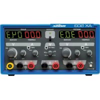
1 Lightning arrester supports
2 Lightning arrester test unit
3 Voltage present indicator
4 Lightning test scale in volts
5 2000 MΩ - 500 V scale
6 200 MΩ - 100 V scale
7 20 MΩ - 50 V scale
8 Battery test scale
9 2000 MΩ - 500 V insulation resistance
10 200 MΩ - 100 V insulation resistance
11 20 MΩ - 50 V insulation resistance
12 Surge arrester test position
13 Battery test position
14 Power OFF
15 Measurement selector switch
16 Lightning arrester test start push button
17
Lightning arrester sliding selection switch
BESCHREIBUNG
1.1. Precautions and safety measures 8
1.1.1.Before use 8
1.1.2.During use 9
1.1.3.Symbols 9
1.1.4. Instructions 9
1.2. Safety devices 9
1.3.Guarantee 9
1.4. Metrological verification 9
2. INSTRUMENT DESCRIPTION 10
2.1. Power supply 10
2.1.1. Self-checking of batteries 10
2.1.2. Replacing the batteries 10
2.2. Scale 11
2.3. Input terminals 11
2.3.1. Discharger support unit 11
2.3.2.Probe 11
3. FUNCTIONAL DESCRIPTION 12
3.1. Discharger test 12
3.2. Insulating resistance measurement at 50V / 20M or 100V / 200M or 500V / 2000M 12
4. GENERAL CHARACTERISTICS 13
4.1. Characteristics 13
4.2. To order 13
1. GENERAL INSTRUCTIONS
You have just purchased a discharger tester / megohmmeter and we thank you for your confidence in us.
This instrument complies with IEC safety standard 61010-1 + A2, dealing with electronic measurements. If you want to obtain the best service, please read these instructions carefully and respect usage precautions.
1.1. Precautions and safety measures
1.1.1.Before use
- The surge arrester support clamp must not be used on live circuits
- The surge arrester tester was designed for use indoors in an environment with a degree of pollution 2, altitude >2000m , temperature between 0^ and 45^ , and relative humidity 80% up to 31^ .
It can be used with its probe and its lead in category III installations, with voltages which never exceed 300V in relation to the earth. - The surge arrester support unit must not be connected to live circuits.
- Definition of installation categories according to IEC standard 664 :
CATI: Category I equipment is equipment which can be connected to circuits in which measurements are taken to limit transient voltage surges to an appropriate low level. Example: protected electronic circuits
CAT II: Category II equipment is energy consuming equipment powered via a permanent installation. Example: household appliance and portable tool power supplies
CAT III: Category III equipment is permanent installation equipment and equipment subject to special specifications, for reasons of reliability and availability. Example: industrial machinery or instrument power supplies
CAT IV: Category IV equipment is used at the installation feed point. Example: power feeder
- The user should respect normal safety rules when he uses the discharger tester / megohmmeter, in order to:
- protect himself against dangers due to electrical current,
- protect the instrument against any false maneuvers.
- The cables and connection accessories used must satisfy IEC standard 61010-2-031 + A2 and must be designed for a rated voltage and overvoltage category at least equal to the values for the circuits on which the measurements are made.

This instrument gives a continued voltage in excess of 500 V on the 200 Mohm calibre and on the lightning arrester calibre test. Never touch the probe tip when the probe is activated.
1.1.2. During use
Never exceed the limiting protection values given in the specifications specific to each measurement type.
1.1.3. Symbols

Refer to the user's manual. Incorrect use may result in damage to the device or its components.

Risk of electric shock

Earth

Appliance protected by dual Insulation or reinforced Insulation

According to WEEE directive 2002/96/EC
1.1.4. Instructions
- Any adjustment, maintenance or repair to the instrument when live must be done by qualified personnel after reading the instructions in this manual.
- A qualified person is anyone familiar with the installation, construction, usage and the dangers involved. This person is authorized to switch the installation and equipment on or off in accordance with safety rules.
- Before opening the device, always disconnect it from all measurement circuits and make sure that there is no static electricity charge which could damage internal elements.
- When the instrument is open, some internal capacitors may maintain a dangerous potential even after the instrument is switched off.
- If there are any abnormal faults or constraints, take the instrument out of service and prevent it from being used until it has been verified.
- It is recommended to connect the cables or insert the element to be tested before initiating the measurement process.
- Place the switch in the OFF position when the instrument is not being used.
1.2. Safety devices
- The switch has two stops that prevent it from rotating.
- It is impossible to access the battery box without firstly disconnecting measurement cables.
An indicator (lamp on the instrument dial) indicates if any mains voltage is present.
1.3. Guarantee
Unless specifically mentioned otherwise, the guarantee is applicable for 12 months after the equipment has been handed over (extract from our general conditions of sale available on request).
1.4. Metrological verification

A periodic verification is necessary, as for all measurement or test instruments.
For checking and calibrating your instrument, please contact our accredited laboratories, the manufacturer subsidiary or agent in your country.
1.5. Repair
Return your instrument to your distributor for any work to be done within or outside the guarantee.
1.6. Maintenance
Clean the instrument with a damp cloth and soap. Let it dry before using it again. Never use abrasive products or solvents.
2. INSTRUMENT DESCRIPTION
This surge arrester tester, associated with a megohmmeter, is designed to provide you with a strong guarantee of safety, maximum protection and unequalled performance. It allows the insulating resistance measurement of earth circuits.
It is a portable, professional, standalone measuring instrument for use by electricians, in order to measure the following magnitudes :
surge arrester voltage
insulating resistance up to 2000 MΩ under 500 VDC
insulating resistance up to 200 MΩ under 100 V DC
insulating resistance up to 20M under 50 VDC
These magnitudes can be accessed using a rotary switch.
2.1. Power supply
The discharger tester is powered by three standard 1.5 V batteries (type LR03) that provide an endurance of about 1500 measures of five sec.
2.1.1. Self-checking of batteries : TEST
Before carrying out a measurement campaign, it is important to check that the instrument power supply batteries are in good condition.
The TEST position of the rotary switch indicates the state of the batteries (it is necessary to press the probe push button).
On the scale, there is an area with two different colours :
- if the needle is positioned in the black area, batteries are charged,
- if the needle is positioned in the red area, batteries are discharged. They must then be replaced.
2.1.2. Replacing the batteries

Unplug measurement circuit test cables, put the rotary switch to the OFF position and remove test cables and the discharger support unit from the instrument.
Proceed as follows to replace the discharger tester batteries :
- Remove the four screws from the back of the instrument.
- Remove the lower box.
- Replace the batteries, taking care that they are in the right direction.
- Close the instrument.
2.2. Scale
The measurement readout is of the analog type. The discharger tester is fitted with a graduated scale and a needle.
The scale is graduated to give a direct reading without any multiplication factor (logarithmic graduation). The scale length is 79mm (circular arc according to IEC standard 51):
discharger tester scale graduated from 0 V to 600 VDC (black scale)
-logarithmic scale for the 2000M 500V range (blue scale)
-logarithmic scale for the 200M 100 V range (blue scale)
-logarithmic scale for the 20M 50V range (blue scale)
- TEST scale containing 2 colors (white and red scale)
2.3. Input terminals
Measurements are performed :
- either with a specific probe (equipped with a push button) connected to the input terminals through a grey cable and a tripod connector, together with a black lead with a probe tip or an alligator clip
- or with a discharger support unit equipped with 4 male plugs to be connected to the 4 input terminals of the instrument box.
2.3.1. Discharger support unit
This unit is a moulded box with 4 male plugs to be connected to the discharger tester.
On the front face of the unit is to be found :
- 2 recesses to accommodate two different discharger types
- a sliding switch used to select one of the two arresters (twin type) when the test is carried out,
- a push button to launch the measurement.
2.3.2. Probe
The probe allows measurement to be triggered directly from the probe tips by means of a push button. The probe comprises three parts:
-
a probe tip with :
-
a test probe of 4mm diameter and 18mm length
-
a push button for initiating external surge arrester tests or insulating resistance tests
-
a cable with 3 wires (0.5 mm each) of 1.5 mm length
- a tripod plug which is connected to the measurement instrument.
This plug is fitted with a failsafe device to prevent connection errors.
3. FUNCTIONAL DESCRIPTION
3.1. Discharger test
Switch the commutator to the position
Surge arrester tests can be conducted in two different ways:
a) Table measurement
The instrument is equipped with a surge arrester support unit. The arrester to be tested is then inserted into the appropriate recess. Press the push button to initiate measurement.
b) Onsite measurement
Connect the earth lead and the probe with the tripod plug to the instrument. Place the two ends of the probe tips of the leads on the surge arrester to be tested. Activate the probe push button to initiate measurement. The surge arrester support clamp can be used for this type of measurement.
Read the voltage value on the 600 V scale :
Accuracy : class 10 (10 % of scale range according to ref. conditions)
- Open-circuit output voltage < 950 V DC
- Short-circuit current < 400 A

The surge arrester support clamp and the surge arrester support unit must not be connected to live circuits.
3.2. Insulating resistance measurement at 50V / 20M or 100V / 200M or 500V / 2000M
High voltage is generated at the terminals of the resistor to be measured. The voltage drop measured at the terminals of a known internal resistor in series with the resistor to be measured is used to deduce the value of the resistor.
Tests should only be carried out on circuits out of voltage (the mains light on the instrument scale must be off after disconnecting the test leads and before pressing the probe push button).
Connect the circuit to be measured to the instrument terminals, before starting the measurement.
Measurement results may be distorted by the impedances of additional circuits connected in parallel or by transient currents.
Measurement range: 100 kΩ to 20 MΩ at 50 V 500 kΩ acc. IEC 61557-2, 100 kΩ to 200 MΩ at 100 V with BAT test in the black area 5 MΩ to 2000 MΩ at 500 V
When the circuit is open (infinite Rx), the needle comes to a stop on the right.
The measured value is read off three specific logarithmic scales: 2000 MΩ / 500 V, 200 MΩ / 100 V and 20 MΩ / 50 V, each covering 3 decades.
Measurement current: ≥ 1mA for R = 500k
≤ 4 mA in short-circuit
Protection of inputs: up to 600 V rms
No load voltages: < 75 V dc on the 50 V range
< 150 V dc on the 100 V range
< 750 V dc on the 500 V range
Accuracy : class 10 (10% of scale range according to ref. conditions)
4. GENERAL CHARACTERISTICS
4.1. Characteristics
Safety according to IEC 61010-1 + A1 + A2
class 2, CAT III 300 V with respect to the earth degree of pollution 2, except surge arrester support unit and surge arrester support clamp
Electromagnetic compatibility EMC Transmission acc. to EN 61326-1
Immunity acc. to EN 61326-1
Environment
Reference temperature 18^ to 28^
Usage temperature 0^ to 45^
Use indoor
Altitude < 2000m
Influence of temperature 0.1 times the class l^
Relative humidity 80% up to 31^
Instrument protection degree IP 40 / IK 04
Power supply
3 batteries 1.5 V alkaline type (LR03)
Endurance typical 1500 × 5 measurements
Mechanical characteristics
Dimensions 155 x 98 x 40 mm
Weight (without batteries) 350 g
Discharger support unit 110 g
4.2. To order
Discharger tester. MX0604
Delivery
1 discharger support unit
1 linked control probe
1 red probe tip
1 black 1.2m flush right-right lead, with integrated grippers
1 black crocodile clip
1 surge arrester support clamp
1 strap, attached to the instrument
3 alkaline batteries (LR03, not mounted)
1 user's manual in five languages
1 carrying case
Spares
1 detachable surge arrester support unit .HX0015
1 linked control probe. .HA1340
1 set of probe tips (black and red) . HA2045
1 black 1.2 m flush right-right lead, with integrated grippers.. .HX2003
1 black crocodile clip . HA2050
1 lightning arrester support clamp.. HX0017
1 strap to be attached to the instrument.. .AF009701S
1 carrying case. HX0016
INHALT
La garantía es valida, salvo indicación explicita, durante un periodo de 12 días after the date of the meeting, where you can find a list of all the activities that will take place during the meeting.
1.4. Verónica metrologica