SWD30012 - Inverter VOLTCRAFT - Free user manual and instructions
Find the device manual for free SWD30012 VOLTCRAFT in PDF.
| Product type | Inverter |
| Brand | Voltcraft |
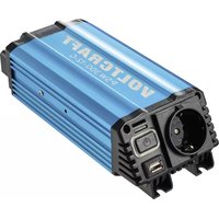
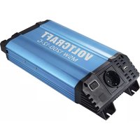
| Model | SWD30012 (SWD-300/12) |
| Nominal input voltage | 12 V/DC |
| Input voltage range | 11 - 15 V/DC |
| Maximum input current | 31 A |
| Output voltage | 230 V ± 2 %, 50 Hz ± 1 % |
| Continuous output power | 300 VA |
| Maximum output power (2 s) | 600 VA |
| Typical efficiency | 90 % |
| USB output | 5 V/DC, 500 mA |
| Dimensions (L x W x H) | 263 x 164 x 88 mm |
| Weight | 1.8 kg |
| Operating temperature (up to 66% load) | -25 to +60 °C |
| Operating temperature (up to 100% load) | -25 to +40 °C |
| Reverse polarity protection | Yes, prevents startup |
| Undervoltage protection (deep discharge) | Yes, adjustable threshold from 9.0 to 11.5 V |
| Overvoltage protection | Yes, triggers at 16 V |
| Short circuit and overload protection | Yes, with automatic restart |
| Thermal protection | Yes, with controlled fan |
| Standby function | Yes, adjustable via DIP switch |
| Optional remote controls | FB-01 SWD (wired), FB-02 SWD (wired LCD), FB-03 SWD (wireless LCD) |
| Maintenance | Clean with a dry, antistatic, lint-free cloth |
| Repairs | Only by a qualified technician |
Frequently Asked Questions - SWD30012 VOLTCRAFT
User questions about SWD30012 VOLTCRAFT
0 question about this device. Answer the ones you know or ask your own.
Ask a new question about this device
Download the instructions for your Inverter in PDF format for free! Find your manual SWD30012 - VOLTCRAFT and take your electronic device back in hand. On this page are published all the documents necessary for the use of your device. SWD30012 by VOLTCRAFT.
USER MANUAL SWD30012 VOLTCRAFT
Sinus Converter SWD Series
GB OPERATING INSTRUCTIONS Page 21-37
These operating instructions belong with this product. They contain important information for putting it into service and operating it. This should be noted also when this product is passed on to a third party.
Therefore look after these operating instructions for future reference!
A list of contents with the corresponding page numbers can be found in the index on page 21.

Satelliten-Receiver ca. 40 W
LCD-Monitor 20^a ca. 75 W
Thank you for making the excellent decision of purchasing this Voltcraft® product.
You have acquired a high-quality product with a brand name that stands out for professional competence and permanent innovation in the field of measuring, charging and power technology.
With Voltcraft®, you will be able to cope even with difficult tasks as an ambitious hobbyist or as a professional user. Voltcraft® offers reliable technology with an exceptional cost-performance ratio.
Therefore, we are absolutely sure: Starting to use Voltcraft will also be the beginning of a long, successful relationship.
Enjoy your new Voltcraft® product!
Table of Contents
Introduction 21
Intended Use 22
Description of Individual Parts 23
Safety and Hazard Notices 24
Functional Description 27
DC Connection 27
Start-up 29
Standby Operation 29
USB Voltage Output 30
Protective Functions 30
Protection Against Wrong Polarity 30
Over-Voltage Protection 30
Undervoltage Cutoff (Deep Discharge Protection) 30
Temperature Protection Switch 31
Overload Protection 31
Remote Control 32
Address Settings 32
Disposal 33
Maintenance and Cleaning 33
Troubleshooting 34
Technical Data 36
Intended Use
The digital converters generate a clean sinus alternate voltage of 230 V/AC from 12 or 24V direct voltage, depending on model. This enables the connection of many different 230V consumers to 12 or 24V direct voltage sources, e.g. in cars, boats or solar installation in weekend houses or when camping.
Due to the high peak load, the absolutely clean output voltage and the high degree of efficiency, you can also operate devices with synchronised power units, converters such as TV and SAT systems, audio systems, tools with electrical motors, pumps, household appliances, compressors, chargers for mobile phones or notebooks, etc..
The maximum output of the 230V consumer is indicated in the technical data (permanent output). Devices with a higher power consumption than the stated permanent output may not be connected.
When connecting devices with electric drives (e.g. power drills, refrigerators, etc.), please note that these may require a higher start-up power than indicated on the type plate.
The product is designed for private use rather than commercial purposes.
Operation is only permitted in a dry environment; contact with moisture must be avoided at all times.
The SWD series converter was manufactured pursuant to the latest state of the art. The devices fulfil the requirements of the applicable European and national directives and may also be used in public traffic in the area of the StVZO.
Conformity has been established and the relevant statements and documents have been deposited with the manufacturer. To maintain this status and to ensure safe operation, you as the user must observe these operating instructions!
Equipment
-
StandBy function with reduced idle power intake can be switched on
-
Polarity reversal and overvoltage protected input
-
Output short-circuit and overload protected
-
Automatic switch-off for undervoltage to protect the battery
-
Adjustable dynamic deep discharge protection via optional display remote control
-
USB charger output 5V/DC 500 mA
-
Optional cable or radio remote controls available
-
Output data can be read through optional display remote control
Operation under adverse environmental conditions is not permitted.
Unfavourable ambient conditions are:
-
Ambient temperatures >50^
-
Wetness or too high air humidity (>80%) rel. humidity
-
presence of dust or combustible gases, vapours or solvents
-
thunderstorms or similar conditions such as strong electrostatic fields etc.
Any use other than that described above will damage the product and may involve other risks, such as short-circuit, fire, electric shock, etc. Do not change or modify any part of the product!
Always observe the safety instructions!
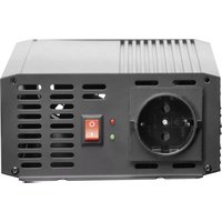
Description of individual parts
(see fold-out page)
1 Fastening hoop
2 DC-input minus pole " -" for 12 or 24 V
3 DC-input plus pole "+" for 12 or 24V
4 DIP switch for mode settings
1 Not assigned
2 StandBy function
3 and 4 address for LCD remote control
5 Connection 1 for display remote control FB-02 SWD or FB-03 SWD
6 Connection 2 for display remote control FB-02 SWD or FB-03 SWD
7 Connection for cable remote control FB-01 SWD
8 USB charger output 5V/DC max. 500 mA
9 LED control display for DC input
10 LED control display for AC output
11 On/Off switch
12 Foldable protective cover for mains socket
13 AC output (230 V mains socket)
14 Ventilation opening
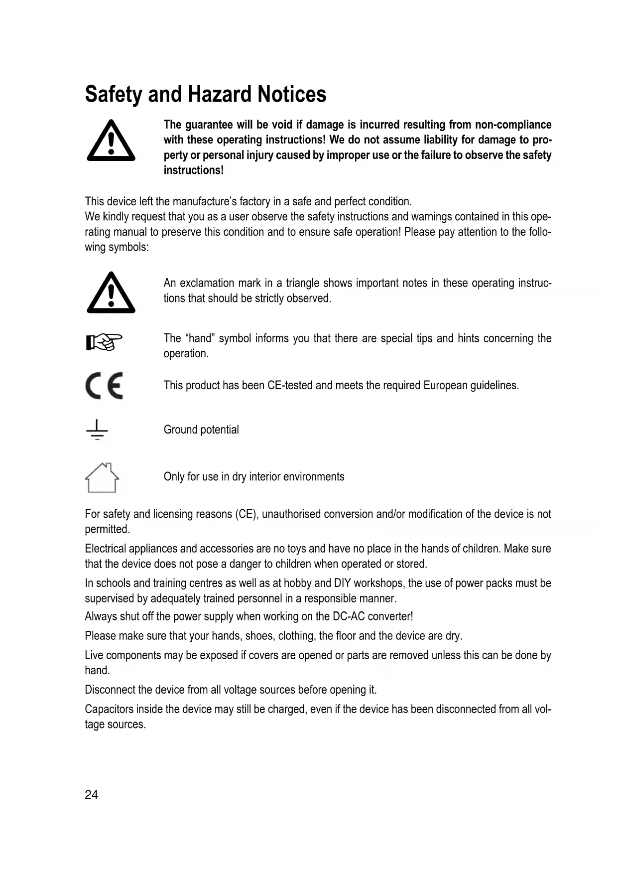
Safety and Hazard Notices

The guarantee will be void if damage is incurred resulting from non-compliance with these operating instructions! We do not assume liability for damage to property or personal injury caused by improper use or the failure to observe the safety instructions!
This device left the manufacture's factory in a safe and perfect condition.
We kindly request that you as a user observe the safety instructions and warnings contained in this operating manual to preserve this condition and to ensure safe operation! Please pay attention to the following symbols:

An exclamation mark in a triangle shows important notes in these operating instructions that should be strictly observed.

The "hand" symbol informs you that there are special tips and hints concerning the operation.

This product has been CE-tested and meets the required European guidelines.

Ground potential

Only for use in dry interior environments
For safety and licensing reasons (CE), unauthorised conversion and/or modification of the device is not permitted.
Electrical appliances and accessories are no toys and have no place in the hands of children. Make sure that the device does not pose a danger to children when operated or stored.
In schools and training centres as well as at hobby and DIY workshops, the use of power packs must be supervised by adequately trained personnel in a responsible manner.
Always shut off the power supply when working on the DC-AC converter!
Please make sure that your hands, shoes, clothing, the floor and the device are dry.
Live components may be exposed if covers are opened or parts are removed unless this can be done by hand.
Disconnect the device from all voltage sources before opening it.
Capacitors inside the device may still be charged, even if the device has been disconnected from all voltage sources.
Avoid sudden temperature fluctuations! This may easily lead to condensation inside the device! In this case, the device must be adjusted to the new ambience temperature before start up for at least one hour in a well-ventilated place.
The converter heats up in operation; ensure that it is adequately ventilated. Do not cover the ventilation apertures of the device!
Do not leave converters and the connected consumers running without supervision.
Ensure sufficient ventilation of the DC-AC converter and the batteries. Battery vapours may ignite because of the DC-AC converter. Therefore, the battery and the converter must be installed in separate spaces.
Do not connect the 230V output of the DC-AC converter with another 230V source.
The converter is not designed for application to human beings or animals or for life-supporting medical devices.
Never expose the device to mechanical stress. Dropping the device even from a low height may damage it! Avoid vibrations and direct sunlight.
If you have reason to believe that the device can no longer be operated safely, disconnect it immediately and make sure it is not unintentionally operated. It must be assumed that safe operation is no longer possible if:
- the device shows visible damage,
- the device no longer works and
- the device was stored under unfavourable conditions for a long period of time or
- after it was exposed to extraordinary stress caused by transport.
Observe also the additional safety instructions in each chapter of these operating instructions as well as in the operating instructions of the connected devices.
Observe that parts of the converter will continue to be live after the protective device (fuse) is triggered!
Handle the product with care. It can be damaged through impact, blows, or accidental drops, even from a low height. Have the device checked by trained specialists in this case before recommissioning.
If you notice any damage, the device must not be used anymore. Take the device to a specialized workshop or dispose of it in an environmentally friendly way.
Damaged connection cables must be exchanged to prevent hazards! Only use suitably sized connection cables (see "Technical Data").
Repairs on this device may only be performed by specialists. Improper repairs may result in substantial hazards! In case of repairs, contact our service department.
Never use the device on hot surfaces. Make sure that ventilation slots are not covered up. Protect the converter from heat! If the converter heats up too far due to excessive ambience temperatures, the overheating protection switches off the device to prevent subsequent damage. In this case, wait until the device has cooled off.
When using the device in vehicles, secure it properly to ensure correct operation of the vehicle.
Prior to activating the device, make sure that the cable and plug are dry. Never operate the device with wet hands.
Only operate the device under supervision.
Only install the device on low or non-flammable surfaces.
Only operate fluorescent tubes with the converter if they are equipped with an electronic starter or control unit. Operation with conventional starters may cause considerable damage to the converter.
AC outputs of several power sources must not be connected in parallel! No AC generators or mains voltage must be connected to the AC output of the converter. This will immediately destroy the converter!
Keep the converter and lead batteries away from ignition sources or open fire! There is a danger of explosion!
The converter has 230V/AC at the output. Even when switched off, the charged capacitors may still briefly carry 230 V/AC at the output. Never open the converter! The inside of the device may be subject to dangerous voltages even after disconnection from the battery. Service and repairs therefore have to be performed by authorised specialists.

Improper assembly may cause dangerous contact voltages even in the closed device!
Battery notes
Lead batteries pose a great danger for people, animals and the environment in case of improper use. Always observe the safety instructions of the battery manufacturer!
Lead batteries contain aggressive and corrosive acids. Avoid skin or eye contact with battery fluids! Never dismantle batteries! On skin contact, clean the affected areas thoroughly with water and soap. On eye contact, rinse the effected eye immediately with clear and cold running water! Then consult a doctor immediately! If your clothes have come into contact with acid, wash your clothes immediately with a lot of water and soap!
Observe the safety instructions of the battery manufacturer.
Functional Description
The SWD series converters are modern, micro-processor-controlled devices developed for mobile power supply. The converters convert 12 or 24 V/DC input voltage into a higher AC output voltage depending on type, thus enabling operation of conventional portable 230V/AC consumers.
These devices offer true sinus alternate voltage, which makes it possible to even operate so-called difficult consumers such as computers, TV systems and devices with converters or motors without any problems.
All SWD series devices are equipped with all required safety features required for a modern product.
Equipment features
- True 230V/AC 50Hz sinus output voltage
- Galvanically isolated
- High efficiency
- StandBy function
- Output and temperature-controlled ventilator
- Soft-start function for consumers with high start-up current
- Different remote controls available as accessories
-Over-voltage protection - Adjustable dynamic deep discharge protection via optional display remote controls
- Overload management
- Short circuit switch-off
- Protection against wrong polarity
- Temperature Protection Switch
DC Connection
Use cables that are as short as possible and with sufficient cross-section for the connection of the DC line and ensure good contact both at the battery and the converter.
Too think or loose connections can cause fire due to overheating!
The operating switch (11) at the front of the device must be set to "OFF" (Position 0).
A high-current fuse must be installed right at the battery. If this fuse is not there, short-circuits at the two connection cables may cause fire.

Charging the large capacitors inside the converter may cause a spark upon connection of the fuse. This device is completely harmless.
The input voltage may not exceed the stated range (see technical data)!
In case of reversed polarity, the converter cannot be put into operation. Connect it in correct polarity.

The DC connection and supply must be designed for the maximum input current of the DC-AC converter (see technical data).
As high currents flow through the connection cables when operating the DC-AC converter (see technical data), the connection cables must be dimensioned accordingly.

The thicker and shorter the connection cable, the lower the voltage drop in the cable.
A high voltage drop may lead to undervoltage of the DC-AC converter, although the battery provides sufficient supply voltage. Therefore, it is important to keep the connection cable as short as possible.
The devices require at least the following cable cross sections:
| Cable cross section at Cable cross Cable length up to 2 m Cable length | section at up to 3 m | |
| SWD-300 16 mm | 2 | 16 mm² |
| SWD-600 16 mm | 2 | 16 mm² |
| SWD-1200 25 mm | 2 | 35 mm² |
| SWD-2000 35 mm | 2 | 50 mm² |

We urgently recommend securing the connection cable with a separate fuse close to the battery to prevent damage to the battery through short-circuits of the connection cables (worn cables, etc.). The fuse must be designed for the max. DC input current of the DC-AC converter.
Due to the high currents, you have to ensure an impeccable connection of the connection cables with the battery and the DC-AC converter.

We recommend only using the optional connection cables.
Prior to attaching the DC-AC converter to the battery voltage, turn it off. For this, put the switch (11) in the "0" position (Off).
The converter is connected to the supply voltage via the two input clamps (2 and 3). The plus pole of the battery must be connected to the input clamp "+" (3), the minus pole of the battery to the input clamp " -" (2).

Always ensure a tight and safe connection of the connection cables to the battery as well as the DC-AC converter. A bad connection leads to high transition resistance and results in overheating.
Start-up

Do not operate any devices connected to the converter while driving.
After connection to the battery, you may commission the DC-AC converter.
Connect a consumer with suitable rated output to the output socket (13).
Switch on the converter with the operating switch (11). Switch position "1" (On) If the connection is correct, the two displays (9) and (10) light up now and indicate correct operation.
LED indicator lamps
The green LED indicator lamps 9 (DC input) and 10 (AC output) supply important information about the converter's operating state. The two LEDs are working independently of each other. This means that any interference in the DC input area directly influences the function of the AC output and that an interference of the output area directly influences the input function.
| Operating mode/interference displays LED 9 | (DC input) LED 10 (AC output) | |
| Device is switched on and ready for operation. Is lit Is lit | ||
| Preliminary warning for deep discharge Flashing slowly Is lit protection | ||
| Switch-off due to deep discharge protection Flashing quickly Flashing quickly | ||
| Overvoltage at input Flashing quickly Flashing quickly | ||
| Short circuit or overload at the output Flashing quickly Flashing quickly | ||
Standby Operation
In StandBy operation, the converter was switched off and verifies that a load >10 watt is present at the output at intervals of approx. 20 s. This reduces internal power consumption and relieves the connected DC power source.
If a load >10 watt is recognised, the output switches to normal operation. When the consumer was switched off, the converter automatically goes back to StandBy mode.
To activate this mode, put the small switch no. 2 to "ON" at the DIP switch (4). The switch points downwards.
To switch off this function, put the small switch no. 2 upwards. The converter is in continuous operation again.

USB voltage output
Different USB-supplied small standard devices such as MP3 players, mobile phones, etc. can be connected directly to the converter and charged. The USB output is only active when the converter is in operation.
Plug the small USB device into the USB socket (8) and switch on the converter.
The USB output is only used to supply small USB devices. Do data is transmitted.
Protective functions
The DC-AC converter is equipped with extensive protective functions, which ensure safe operation and protect the DC-AC converter, the battery and the connected consumer.
Protection against wrong polarity
When the input polarity is reversed upon connection, the converter cannot be taken into operation. Switch off the converter and verify correct polarity. Connect the converter with the correct polarity. The converter can be put into operation again after correct connection.
Over-Voltage Protection
The DC-AC converter switches off the output automatically as soon as the input voltage exceeds the admissible range (see technical data). This switch-off is indicated by quickly flashing LED displays.
When the input voltage is reduced to the permitted voltage value again, the converter switches on again automatically.
Undervoltage Cutoff (Deep Discharge Protection)
The DC-AC converter switches off the output automatically as soon as the input voltage undercuts the admissible range (see technical data).
Before the output is switched off, however, LED (9) flashes slowly as a warning. When the input voltage sinks farther and reaches the cut-off value, the output is switched off. This switch-off is indicated by quickly flashing LED displays (9) and (10).
The undervoltage cut-off normally triggers when the batteries are empty. In most cases, it is sufficient to recharge the battery. When the reactivation threshold is reached, the converter switches back to normal operation.

The undervoltage switch-off is dynamic. The switch-off threshold set is automatically reduced by up to 1.0V under increased load. This balances out shorter operating times for power sources with lower voltages.
The voltage threshold for the undervoltage cut-off function is set in the factory but can be customised with an optional display remote control (e.g. FB-02 SWD or FB-03 SWD). Setting is described in the remote control's operating instructions.
The reactivation threshold is fixed in the factory and cannot be changed.
Temperature Protection Switch
The converter is equipped with an output- and temperature-controlled device ventilator. Where the temperature inside the device is too high, the converter automatically switches off the output for reasons of security. Do not switch off the converter and let it first reach normal operating temperature. The output is reactivated automatically.
Overload Protection
The DC-AC converter cuts off automatically in case of an overload. Overloads may occur when the permanent output or power intake are exceeded or when there is a short circuit on the output.
The converter is equipped with an automatic reactivation (soft start) after overload. This restart especially makes sense in case of consumers with a high start-up power. If reactivation is not possible even after repeated attempts, the consumer is not suitable for operation at the converter.
The output is switched on automatically when the overload or short circuit at the overload was removed.
General information on operating alternate current consumers on DC-AC converters
In principle, you can operate all 230 V consumers on DC-AC converters. However, on order to estimate the power requirement and the corresponding reserves, it is important to know some properties of typical 230 V consumers.
Many 230 V consumers require a much higher start-up output than the permanent output indicated on the type plate.
The start-up output does not play a major role with mains operation, because the corresponding power reserves are always available. However, converters are limited in their output and can only supply the indicated peak output for short periods of time. When the start-up output of a consumer is higher than the peak load, the DC-AC converter is not suitable for this consumer.
Example: A small compressor-operated refrigerator with a permanent output of approx. 50 W requires up to 500 watt in the compressor start-up stage. This refrigerator requires a converter with a peak output of at least 500 W.
Other Examples:
- Light bulb approx. 1 sec. up to 8 times higher start-up output
- Refrigerators approx. 3 sec. up to 10 times higher start-up output
- TVs approx. 1 sec. up to 10 times higher start-up output
DVD player approx. 30 W
SAT receiver approx. 40 W
LCD screen 20" approx. 75 W
Tube TV 55cm tube approx. 80 W
a notebook approx. 70-150 W
Coffee machine approx. 1300 W
Hairdryer approx. 1500 W
Vacuum cleaner approx. 1500 W
Remote Control
All SWD series models are equipped with a remote control function. There are three optional remote controls. They are connected to the converter by special sockets. Operation and connection is explained in the operating instructions of the respective remote control. The following remote control are available:
FB-01 SWD Switch remote control
Simple cable-bound remove control that can be switched on and off and with indicator lamps for input and output.
FB-02 SWD LCD remote control
Cable-bound remote control that displays date and time, input and output voltage and the current output power. This remote control can also be used to customize the deep discharge protection. Furthermore, a SD card slot is available. Here, operating data can be stored on optional SD memory cards and evaluated on the computer. Voltage is supply through the converter.
FB-03 SWD LCD remote control
Wireless remote control with radio transmission. Equipment and operation corresponds to FB-02 SWD. The wireless remote control is supplied by a battery.
Address Settings
Address settings enable control and data readout for up to 4 converters with one LCD remote control. The converter is assigned an address from 1 to 4 by changing the DIP switch position (switch pair 3 and 4). The default address is "4".

When an LCD remote control is connected to only one converter, no address needs to be set with the DIP switch (4) pair 3 and 4. This setting is only needed for several converters with a single remote control.
To set the desired device address, select the respective switch combination with the switch pair 3 and 4 at the DIP switch. Use a pointed object for setting.
The device's address is displayed when the FB-02 SWD or FB-03 SWD remote control is connected.

1

2

3

4
Disposal

Used electronic devices are raw materials and must not be disposed of in the domestic waste. At the end of its service life, dispose of the product at the community collection point according to the relevant statutory regulations. It is prohibited to dispose of the device in the household waste.
Maintenance and Cleaning
Apart from occasional cleaning, the converter is maintenance-free.

Switch off the device before cleaning. Separate it from the supply voltage and the connected consumers if you do not use the DC-AC converter for longer periods.
Use a clean, lint-free, antistatic and dry cloth to clean the device. Do not use any abrasive or chemical agents or detergents containing solvents.
Regularly that the connection cables are still firmly connected at the connection clamps.
Troubleshooting
With this converter, you have acquired a product that is reliable and operationally safe.
Nevertheless, problems or errors may occur.
For this reason we want to describe how to troubleshoot potential malfunctions:

Always follow the safety instructions!
| Error Possible cause | |
| The converter cannot Are the operating indicators (9 and 10) lit? be switched on. Check the voltage supply. Check the input fuse and connection cables for contact. | converter overloaded? converter overloaded? Check the technical data of the consumers. |
| The display (9) flashes. The input voltage indicator (10) is lit normally. Check the display (9) flashes. The input voltage source and recharge the battery as soon as possible if required. | age decreased. voltage source and recharge the battery as soon as possible if required. |
| The displays (9 and 10) flash. The converter is overloaded The AC output is switched off. Check | verter is overloaded the technical data of the consumers. |
| Deep discharge protection is active. Check the voltage source and recharge the battery at once. the converter switches on again automatically at a voltages of 12.5 V or 25 V. | |
| The input voltage rose too far. Switch off the converter and check the power source. |
Regularly check the technical safety of the device e.g. for damaged housing, connection lines, etc.

Any other repair work must always be carried out by a specialist familiar with the hazards involved and with the relevant regulations. Unauthorized modifications or repairs to the device invalidate the warranty/guarantee. Fuses are replacement parts and not covered by the warranty!
Note on selection of the right lead battery
The converter can be operated at any direct voltage source, depending on type (12 or 24 V/DC). However, you need to consider that the voltage source can provide the respective input current for the converter and is protected accordingly.
Preferably, converters are operated at lead batteries, since they can also provide short-term power peaks.
Lead batteries are usually charged by chargers, generators or solar cells. These chargers are also decisive for lead battery regeneration. Recharging with solar cells takes much longer due to the lower efficiency. This must be taken into account for power and capacity determination.
The input current of a converter can be approximately calculated from the output power and efficiency.
$$ \text {I n p u t c u r r e n t} = \frac {\text {O u t p u t p o w e r / e f f i c i e n c y}}{\text {I n p u t v o l t a g e}} $$
Example calculation:
$$ \text {Input current} = \frac {600 \text {Watt / 0.90 (90\%)}}{12 \text {volt}} = 55.6 \text {Ampere} $$
For example, a lead battery must be able to supply 55.6 ampere for a 600W converter in permanent operation. For a 1200W converter, these are 111 ampere already.
A fully charged 12V lead battery with a capacity of 70 Ah is able to deliver 55.6 ampere (600W) for a period of time of approx. 1.2 hours (formula: battery capacity / power) without recharging. Where, e.g., two 100W light bulbs are lit for 8 hours, a battery capacity of at least 160 Ah is required for 12V.
The battery type used also influences the function. Solar batteries usually have a "softer" voltage than starter batteries and thus have to be classified at least 15% higher than the desired application range as starter batteries.
Technical Data
| SWD-300/12 SWD-600/12 SWD-1200/12 SWD-200/12 | ||||
| INPUT | ||||
| Nominal input voltage 12 V/DC 12 | V/DC 12 V/DC 12 V/DC | |||
| Input voltage range 11 - 15 V/DC | 1 - 15 V/DC 11 - 15 V/DC 11 - 15 V/DC | |||
| Max. input current 31 A 62 A 124 A | 248 A | |||
| Switch-off due to deep discharge protection (factory settings) | 10.5 V idle9.5 V rated load | 10.5 V idle9.5 V rated load | 10.5 V idle9.5 V rated load | 10.5 V idle9.5 V rated load |
| Setting area deep discharge protection | 9.0 - 11.5 V | 9.0 - 11.5 V/DC | 9.0 - 11.5 V/DC | 9.0 - 11.5 V/DC |
| Preliminary warning deep discharge protection) | 1.0 V above switch-off | 1.0 V above Switch-off | 1.0 V above Switch-off | 1.0 V above Switch-off |
| Reactivation voltage | 12.5 V | 12.5 V | 12.5 V | 12.5 V |
| Switch-off overvoltage | 16 V | 16 V | 16 V | 16 V |
| Power consumption idle | 4 VA | 5 VA | 9 VA | 13 VA |
| Power consumption StandBy | 0.4 VA | 0.5 VA | 0.9 VA | 1.3 VA |
| OUTPUT | ||||
| Output voltage | 230 V ± 2% | 230 V ± 2% | 230 V ± 2% | 230 V ± 2% |
| Output frequency | 50 Hz ± 1% | 50 Hz ± 1% | 50 Hz ± 1% | 50 Hz ± 1% |
| Permanent output current | 1.3 A effective | 2.6 A effective | 5.2 A effective | 8.7 A effective |
| Permanent output power (cos-phi >0.8) | 300 VA | 600 VA | 1200 VA | 2000 VA |
| Peak output power max. 2s (cos-phi >0.8) | 600 VA | 1200 VA 2400 VA | 4000 VA | |
| Degree of effectiveness | Type 90% | Type 90% | Type 90% | Type 90% |
| Standby switch-off level | Output current <0.1 A | Output current <0.2 A | Output current <0.3 A | Output current <0.4 A |
| Standby switch-on level | >10 W | >10 W | >10 W | >10 W |
| Power plug | 1x protective contact | 1x protective contact | 1x protective contact | 1x protective contact |
| GENERAL | ||||
| USB output type A | 5 V/DC 500 mA | 5 V/DC 500 mA | 5 V/DC 500 mA | 5 V/DC 500 mA |
| Operating temperature (to 66% rated load) | -25 to +60°C | -25 to +60°C | -25 to +60°C | -25 to +60°C |
| Operating temperature (to 100% rated load) | -25 to +40°C | -25 to +40°C | -25 to +40°C | -25 to +40°C |
| Dimensions (LxWxH) mm | 263x164x88 | 277x234x88 | 391x234x88 | 391x234x88 |
| Weight | 1.8 kg 2.9 kg | 3.5 kg | 4.8 kg | |
| SWD-300/24 SWD-600/24 SWD-1200/24 SWD-200/24 | ||||
| INPUT | ||||
| Nominal input voltage 24 V/DC 24 | V/DC 24 V/DC 24 V/DC | |||
| Input voltage range 22 - 30 V/DC | 22 - 30 V/DC 22 - 30 V/DC 22 - 30 V/DC | |||
| Max. input current 15.5 A 31 A 62 A | 124 A | |||
| Switch-off due to deep discharge protection (factory settings) | 21.0 V idle 21.0 V idle 21.0 V idle 21.0 V idle 21.0 V idle 21.0 V idle 21.0 V idle 21.0 V idle 21.0 V idle 21.0 V idle 21.0 V idle 21.0 V idle 21.0 V idle 21.0 V idle 21.0 V idle 22.0 V rated load 19.0 V rated load 19.0 V rated load 19.0 V rated load 19.0 V rated load 19.0 V rated load 19.0 V rated load 19.0 V rated load 19.0 V rated load 19.0 V rated load 19.0 V rated load 19.0 V rated load 19.0 V rated load 19.0 V rating load 19.0 V rating load 19.0 V rating load 19.0 V rating load 19.0 V rating load 19.0 V rating load 19.0 V rating load 19.0 V rating load 19.0 V rating load 19.0 V rating load 19.0 V rating load 19.0 V rating load 19.0 V rating load 18.0 - 23.0 V 18.0 - 23.0 V 18.0 - 23.0 V 18.0 - 23.0 V 18.0 - 23.0 V 18.0 - 23.0 V 18.0 - 23.0 V 18.0 - 23.0 V 18.0 - 23.0 V 18,0 - 23.0 V 18.0 - 23.0 V 18.0 - 23.0 V 18.0 - 23.0 V 18.0 - 23.0 V 18.0 - 23.0 V 18.0 - 23.0 V 18.0 - 23.0 V 18.0 - 124 A | |||
| Setting area deep discharge protection | 18.0 - 23.0 V 18.0 - 23.0 V 18.0 - 23.0 V 18.0 - 23.0 V 18.0 - 23.0 V 18.0 - 23.0 V 18.0 - 23.0 V 18.0 - 23.0 V 18.1 V 18.0 - 23.0 V 18.0 - 23.0 V 18.0 - 23.0 V 18.0 - 23.0 V 18.0 - 23.0 V 18.0 - 23.0 V 18.0 - 23.0 V 18.0 - 23.0 V 17.0 V 17.0 V 17.0 V 17.0 V 17.0 V 17.0 V 17.0 V 17.0 V 17.0 V 17.0 V 17.0 V 17.0 V 17.0 V 17.0 V 17.0 V 17.0 V 17.0 V | 19.0 V rated load 19.0 V rated load 19.0 V rated load 19.0 V rated load 19.0 V rated load 19.0 V rated load 19.0 V rated load 19.0 V rated load 19.0 V rated load 19.0 V rated load 19.0 V rated load 19.0 V rated load 19.1 V 19.0 V 19.0 V 19.0 V 19.0 V 19.0 V 19.0 V 19.0 V 19.0 V 19.0 V 19.0 V 19.0 V 19.0 V 19.0 V 19.0 V 19.0 V 19.0 V 19.0 V 18.0 - 23.0 V 18.0 - 23.0 V 18.0 - 23.0 V 18.0 - 23.0 V 18.0 - 23.0 V 18.0 - 23.0 V 18.0 - 23.0 V 18.0 - 23.0 V | 19.0 V rated load 19.0 V rated load 19.0 V rated load 19.0 V rated load 19.0 V rated load 19.0 V rated load 19.0 V rated load 19.0 V rated load 19.0 V rated load 19.0 V rated load 19.0 V rated load 19.0 V rated load | 19.0 V rated load 19.0 V rated load 19.0 V rated load 19.0 V rated load 19.0 V rated load 19.0 V rated load 19.0 V rated load 19.0 V rated load 19.0 V rated load 19.0 V rated load 19.0 V rated load 19.0 V rated load 19,0 V 19.0 V 19.0 V 19.0 V 19.0 V 19.0 V 19.0 V 19.0 V 19.0 V 19.0 V 19.0 V 19.0 V 19.0 V 19.0 V 19.0 V 19.0 V 19.0 V 23.0 V 23.0 V 23.0 V 23.0 V 23.0 V 23.0 V 23.0 V 23.0 V 23.0 V 23.0 V 23.0 V 23.0 V 23.0 V 23.0 V 23.0 V 23.0 V 23.0 V |
| Preliminary warning deep discharge protection) | 1.0 V above switch-off | 1.0 V above switch-off | 1.0 V above switch-off | 1.0 V above switch-off |
| Reactivation voltage | 25 V | 25 V | 25 V | 25 V |
| Switch-off overvoltage | 32 V | 32 V | 32 V | 32 V |
| Power consumption idle | 4 VA | 5 VA | 9 VA | 13 VA |
| Power consumption StandBy | 0.4 VA | 0.5 VA | 0.9 VA | 1.3 VA |
| OUTPUT | ||||
| Output voltage | 230 V ± 2% | 230 V ± 2% | 230 V ± 2% | 230 V ± 2% |
| Output frequency | 50 Hz ± 1% | 50 Hz ± 1% | 50 Hz ± 1% | 50 Hz ± 1% |
| Permanent output current | 1.3 A effective | 2.6 A effective | 5.2 A effective | 8.7 A effective |
| Permanent output power (cos-phi >0.8) | 300 VA | 600 VA | 1200 VA | 2000 VA |
| Peak output power max. 2s (cos-phi >0.8) | 600 VA | 1200 VA | 2400 VA | 4000 VA |
| Degree of effectiveness | Type 90% | Type 90% | Type 90% | Type 90% |
| Standby switch-off level | Output current <0.1 A <0.2 A | Output current <0.3 A | Output current <0.4 A | Output current <0.4 A |
| Standby switch-on level | >10 W | >10 W | >10 W | >10 W |
| Power plug | 1x protective contact | 1x protective contact | 1x protective contact | 1x protective contact |
| GENERAL | ||||
| USB output type A | 5 V/DC 500 mA | 5 V/DC 500 mA | 5 V/DC 500 mA | 5 V/DC 500 mA |
| Operating temperature (to 66% rated load) | -25 to +60°C -25 to +60°C -25 to +60°C -25 to +60°C -25 to +60°C -25 to +60°C -25 to +60°C -25 to +60°C -25 to +60°C -25 to +60°C -25 to +60°C -25 to +60°C -25 to +60°C -25 to+60°C -25 to +60°C -25 to +60°C -25 to +60°C -25 to +60°C -25 to +60°C -25 to +60°C -25 to +60°C -25 to +60°C -25 to +60°C -25 to +60°C -25 to +60°C -25 to +60°C-25 to +60°C -25 to +60°C -25 to +60°C -25 to +60°C -25 to +60°C -25 to +60°C -25 to +60°C -25 to +60°C -25 to +60°C -25 to +60°C -25 to +60°C -25 to +60°C -25到 +60°C -25to +60°C -25to +60°C -25to +60°C -25to +60°C -25to +60°C -25to +60°C -25to +60°C -25to +60°C -25to +60°C -25to +60°C -25to +60°C -25to +60°C -25to +60°C -25to +60°C -25to +60°C -25to +60°C -25to +60°C -25to +60°C -25to +60°C -25to +60°C -25to +60°C -25to +60°C -25to +60°C -25to +60°C -25to +60°C -25 to +60°C -25to +60°C -25to +60°C -25to +60°C -25to +60°C -25to +60°C -25to +60°C -25to +60°C -25to +60°C -25to +60°C -25to +60°C -25to +60°C -25to +60℃ -25to +60°C -25to +60°C -25to +60°C -25to +60°C -25to +60°C -25to +60°C -25to +60°C -25to +60°C -25to +60°C -25to +60°C -25to +60°C -25to +60°C -25TO +60°C -25TO +60°C -25TO +60°C -25TO +60°C -25TO +60°C -25TO +60°C -25TO +60°C -25TO +60°C -25TO +60°C -25TO +60°C -25TO +60°C -25TO +60°C -25TO +60°C -25TO +60°C -25TO +60°C -25TO +60°C -25TO +60°C -25TO +60°C -25TO +60°C -25TO +60°C -25TO +60°C -25TO +60°C -25TO +60°C -25TO +60°C -25TO +60°C -25 TO +60°C -25TO +60°C -25TO +60°C -25TO +60°C -25TO +60°C -25TO +60°C -25TO +60°C -25TO +60°C -25TO +60°C -25TO +60°C -25TO +60°C -25TO +60°C -25TO +60 °C -25TO +60°C -25TO +60°C -25TO +60°C -25TO +60°C -25TO +60°C -25TO +60°C -25TO +60°C -25TO +60°C -25TO +60°C -25TO +60°C -25TO +60°C -25TO +60°C -24TO +60°C -25TO +60°C -25TO +60°C -25TO +60°C -25TO +60°C -25TO +60°C -25TO +60°C -25TO +60°C -25TO +60°C -25TO +60°C -25TO +60°C -25TO +60°C -25TO +6 | |||

Introduction
Cher client,
Indications relatives aux batteries
LCD-monitor 20" ca. 75 W
Copyright 2010 by Voltcraft

Impressum /legal notice in our operating instructions
These operating instructions are a publication by Volcraft, Lindenweg 15, D-92242 Hirschau/Germany, Phone +49 180/586 582 7 (www.volcraft.de).
All rights including translation reserved. Reproduction by any method, e.g. photocopy, microfilming, or the capture in electronic data processing systems require the prior written approval by the editor. Reprinting, also in part, is prohibited.
These operating instructions represent the technical status at the time of printing. Changes in technology and equipment reserved.
Copyright 2010 by Voltcraft

Copyright 2010 by Voltcraft

Copyright 2010 by Voltcraft
V1_1010_01/AB