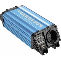
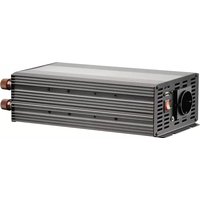
Sinus SW-4000 - Inverter VOLTCRAFT - Free user manual and instructions
Find the device manual for free Sinus SW-4000 VOLTCRAFT in PDF.
| Product type | Inverter |
| Brand | Voltcraft |
| Model | Sinus SW-4000 |
| Order number | 511316 (12V) / 511290 (24V) |
| Dimensions (L x W x H) | 455 x 245 x 70 mm |
| Weight | 5.2 kg |
| Nominal input voltage | 12 V/DC or 24 V/DC (depending on version) |
| Continuous output power | 4000 VA (cos φ >0.8) |
| Maximum output power | 6000 VA (cos φ >0.8) |
| Output voltage | 225 V/AC (+5% / -8%) |
| Output frequency | 50 Hz (±1%) |
| Waveform | Sinusoidal |
| Efficiency | >88% |
| Max. input current | 440 A (12V) / 220 A (24V) |
| Recommended battery capacity | Min. 300 Ah (12V) / min. 150 Ah (24V) |
| Protection | Reverse polarity, undervoltage, overload, overtemperature, short-circuit |
| Cooling | Fan |
| Remote control | Yes (input for external switch) |
| Recommended cable cross-section | 35 mm² (up to 2 m) / 50 mm² (up to 3 m) |
| Input fuses | 6 x 40 A (automotive, 12V) / 6 x 20 A (24V) |
| Output sockets | 1 safety socket + 1 Euro socket |
| Maintenance | Fuse replacement, cleaning with dry cloth |
| Ambient temperature | Indoor use, dry rooms |
Frequently Asked Questions - Sinus SW-4000 VOLTCRAFT
User questions about Sinus SW-4000 VOLTCRAFT
0 question about this device. Answer the ones you know or ask your own.
Ask a new question about this device
Download the instructions for your Inverter in PDF format for free! Find your manual Sinus SW-4000 - VOLTCRAFT and take your electronic device back in hand. On this page are published all the documents necessary for the use of your device. Sinus SW-4000 by VOLTCRAFT.
USER MANUAL Sinus SW-4000 VOLTCRAFT
www.business.conrad.at
- Introduction....22
- Explanation of Symbols 23
- Scope of Delivery....23
- Intended Use 24
- Safety Notes 25
a) General....25
b) Site of Setup....26
c) Connection to a Direct Voltage Source....27
d) Mains Voltage Output 27
e) Operation....28 - Connection to the Voltage Source ....29
a) General....29
b) Earthing....31 - Operation....32
- Remote control ....33
- LED Display....33
- Fuse Change....34
- Maintenance and Cleaning....34
- Troubleshooting....35
- Disposal....35
- Technical Data 36
1. INTRODUCTION
Dear Customer,
thank you for making the excellent decision to purchase a Voltcraft® product.
Voltcraft®This name stands for above-average quality products in the areas of measuring, charging and grid technology, characterised by technical competence, extraordinary performance and permanent innovation.
Whether you are an ambitious hobby electronics or a professional user - a product of the Voltcraft® brand family will provide you with the best solution for even the most sophisticated of tasks. Special features: We offer the sophisticated technology and reliable quality of our Voltcraft® products at a near-unbeatable price/performance ratio. We lay the groundwork for long, good and successful cooperation.
Enjoy your new Voltcraft® product!
All company names and product names are trademarks of their respective owners. All rights reserved.
If there are any technical questions, please contact:
International: www.conrad.com/contact
United Kingdom: www.conrad-electronic.co.uk/contact
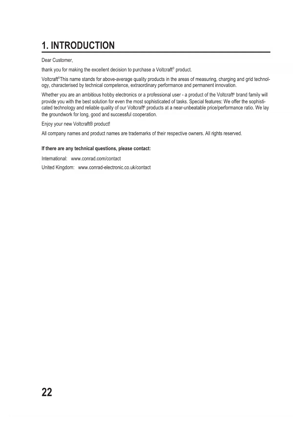
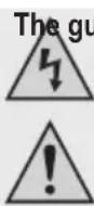
2. EXPLANATION OF SYMBOLS

The symbol with a lightning bolt in a triangle is used where there is a health hazard, e.g. from electric shock.

The exclamation mark in a triangle indicates important notes in these operating instructions that must be observed strictly.

The "arrow" symbol indicates that special advice and notes on operation are provided.

The product is intended for use in dry indoor rooms only; it must not become damp or wet.

Observe the operating instructions.
3. SCOPE OF DELIVERY
- Inverter
- Operating instructions
Depending on the converter version, the following parts are enclosed:
- For converters with pole terminals: Connection cables for remote control (round plugs on 2 open cable ends)
- For item no. 511316 and 511290: Special connection cables with two 5-pin plugs
- For item no. 511700: Wall holder (may already be pushed on at the rear at delivery)
4. INTENDED USE
The converter produces a sine-shaped alternating voltage of 225 V/AC at 50 Hz from a direct voltage (depending on converter version, either with a rated voltage of 12 V/DC or 24 V/DC).
| 12 V/DC 24 V/DC | |
| Item no. 511316 (SW-4000) Item no. | 511290 (SW-4000) |
| Item no. 511258 (SW-2000) Item no. | 511257 (SW-2000) |
| Item no. 511755 (SW-1200) Item no. | 511756 (SW-1200) |
| Item no. 511747 (SW-600) Item no. | 511748 (SW-600) |
| Item no. 511745 (SW-300) Item no. | 511746 (SW-300) |
| Item no. 511743 (SW-150) Item no. | 511744 (SW-150) |
| Item no. 511700 (SW-100) - |
The mains voltage the inverter produces has a true sine shape. Therefore, the inverter also may be used to operate sensitive consumers that react to irregularities in the voltage supply with interferences.
The maximum output of the inverter and other important indices can be found in chapter "Technical Data" at the end of these operating instructions.
Electrical consumers with a higher rated power intake than the maximum permanent output of the inverter must not be connected.
When connecting an electrical consumer (e.g. drill, refrigerator, etc.), to the converter, observe that it often needs a higher output than indicated on the rating plate of the consumer for a short period when switching on or starting up. The converter therefore briefly supplies a higher output. It also offers a soft start function.
The converter also has an undervoltage pre-warning and a deactivation at undervoltage or short circuit. There also is a protection against polarity reversal and an overtemperature protection.
The safety notes and all other information in these operating instructions always have to be observed! Read these operating instructions with care before connection and commissioning. Keep these operating instructions or pass them on to a third party only together with this product.
Any use other than that described above can damage the product and may involve additional risks such as short circuit, fire, electric shock, etc. No part of this product must be modified or converted!
This product complies with the statutory national and European requirements.
rantee/warranty will expire if damage is incurred resulting from non-compliance with the operating instructions! We do not assume any liability for consequential damage!
We do not assume any liability for property damage or personal injury caused by improper use or non-compliance with the safety instructions! In such cases the warranty/guarantee is voided.
Dear Customer, the following safety instructions are intended not only for the protection of your health but also for the protection of the product.
Therefore, read the following items very carefully before connecting the product and taking it into operation.
a) General Information
- The unauthorized conversion and/or modification of the product is prohibited for safety and approval reasons (CE). Never dismantle the product.
- Maintenance, adjustments and repair work may only be carried out by a specialist/specialised workshop. The installed device fuse must only be exchanged by a specialist.
- The product is not a toy and must be kept out of reach of children.
- Do not leave packaging material unattended. It may become a dangerous toy for children.
- Never touch the inverter or any cables with wet or damp hands; danger to life from electric shock!
- Protect all cables from damage. Damaged cables must not be used anymore. Replace them at once
- Place the cables where no one can trip over them.
- Never touch the inverter or any cables of the connected consumer if they are damaged; danger to life from electric shock!
First switch off the inverter and disconnect it from the voltage/current supply.
- Handle the product with care. It can be damaged by impact, blows or when dropped even from a low height.
- Observe the operating instructions of all devices that are connected to the inverter.
- If you are not sure about the correct connection or use of the inverter, or if questions which are not covered by these operating instructions arise, please do not hesitate to contact us or another qualified specialist.


- Keep children away from the product. Choose the site of setup so that children cannot reach it. Children may try to stick objects into the device. There is danger to life from electric shock!
- The product is only suitable for operation in dry, closed rooms. The entire product must never become moist or wet. There is a fatal danger from electric shock!
- Choose a solid, flat, clean and sufficiently large surface for the product. Depending on the operating site, a suitable holder is required (specifically in vehicles).
-
Avoid the following adverse ambient conditions at the site of setup or during storage or transport:
-
dampness or high humidity
- cold or heat, direct solar radiation
- dust or flammable gases, fumes or solvents
- strong vibration, impact or blows,
- strong magnetic fields as present near machines or speakers
- Do not place the product next to a radiator, fan, air conditioning or similar. Keep the product away from dust and dirt.
- Do not put the converter onto the rechargeable battery.
- Never place the product on a flammable surface (e.g. carpet, tablecloth). Always use a suitable, non-flammable, heatproof surface.
- Do not place the product on any valuable furniture surfaces without using suitable protection. Heat may cause colour or material changes. Scratches of pressure points on the furniture surface are possible as well.
- If the converter (depending on version) has an installed fan, place the product so that the fan cannot suck in any loose objects, curtains, etc. This not only poses a danger of damage to the product, but also a danger of fire.
- Keep the product away from easily inflammable materials (e.g. curtains, paper), liquids (e.g. petrol) or gases. There is a risk of fire and explosion!
This specifically applies to gases escaping from rechargeable batteries (e.g. for lead batteries). Therefore, observe the corresponding ventilation and do not place the inverter and the rechargeable battery in the same room.
- Keep the inverter away from sources of open fire (e.g. candles), and do not place them on the inverter.
- The product must be easily accessible so that it can be switched off or disconnected from the voltage source quickly in case of error.
- Avoid operation in direct proximity of strong magnetic or electromagnetic fields, transmitter aerials or HF generators. This can affect the control electronics.
- Do not place any containers filled with liquid, e.g. vases or plants, on or next to the product.
Liquids entering the inverter will destroy it. There also is the utmost risk of potentially fatal electric shock.
In this case, disconnect the product from the voltage/current supply at once. No longer operate the product. Have the product inspected by a specialist workshop or dispose of it environmentally compatibly.
- Secure or attach the inverter and all cables, e.g. when using them in a vehicle, so that proper operation of the vehicle is ensured and the inverter cannot come loose.
connection to a Direct Voltage Source
- Do not wear any metal or conductive materials, such as jewellery (necklaces, bracelets, rings, etc.). A short circuit at the rechargeable battery or inverter causes a danger of injury, fire and explosion.
- For a converter with pole terminals, a suitable connection cable with a sufficiently large line cross-section must be used (see chapter "Technical Data"). The longer the connection cable, the larger the line cross-section has to be. If the line cross-section is too small, the connection cable may grow hot. There is a danger of fire! Keep the connection cable between the converter and the rechargeable battery as short as possible for this reason.
Very strong overheating may also cause a defect to the insulation of the connection cable, which may cause short circuit. There is a risk of explosion of the rechargeable battery, as well as danger of fire!
A converter with pole terminals should never be directly connected to a direct voltage source (e.g. a car battery), but only via an accordingly sized fuse. This fuse should be placed as close as possible to the direct voltage source.
- At a converter with cigarette lighter plug (types "SW-100" and "SW-150"), the connection cable must not be cut off, shortened or extended.
- Before the inverter is connected to the direct voltage source, it must be switched off.
- Always observe the correct polarity (plus/+ and minus/--) for connection of the converter.
- Depending on the power taken from the inverter, the direct voltage source (e.g. a car battery) must be able to supply the corresponding current strength.
- Check all connections for tight fit and good electrical contact at regular intervals. High transfer resistances not only reduce the performance of the inverter but also may cause overheating and fire.
- The inverter must not be connected to electrical systems (e.g. a motor vehicle) where the plus pole is grounded or connected to the chassis of the vehicle.
d) Mains Voltage Output
- Do not pull the mains plug from the mains socket of the inverter by pulling the cable.
- Never connect the output of the inverter to another 230 V source (e.g. a mains socket). The inverter must not be used to feed mains voltage into an electrical building installation.
- In the deactivated condition, the charged capacitors may still cause the alternating voltage to be pending at the mains sockets of the converter.
e) Operation
- Do not operate the inverter unsupervised.
- Never touch the blank live contacts or connection terminals on the input side of the converter.
- Even after triggering the internal protective device or device protection, parts of the converter may still be live!
- The housing of the inverter will heat up in operation (depending on the output). Therefore, always observe sufficient ventilation of the inverter; never cover it in operation. Never close the ventilation slots of the inverter.
Keep a minimum distance of 10 cm from other devices around the housing of the inverter.
er operate the inverter immediately after it has been taken from a cold room to a warm room.
The resulting condensation may lead to malfunctions or damage! Moreover, there is the risk of a fatal electric shock!
Let the inverter reach room temperature before connecting and operating it. This may take several hours!
- Only operate the inverter in a moderate climate, never in a tropical climate. For more information on acceptable environmental conditions, see the chapter "Technical Data".
- Never overload the inverter. In spite of comprehensive protective circuits, a defect or damage to the inverter or the connected devices cannot be fully excluded.
- The inverter is not approved for operation in connection with life-supporting medical devices.
- Deactivate the inverter and disconnect it from the voltage/current supply when you do not need it anymore. Keep it in a clean, dry, cool place that is inaccessible to children.
- In schools, training centres, hobby and self-help workshops, the use of the product must be supervised by responsible trained personnel.
- In commercial institutions, the accident prevention regulations of the Employer's Liability Insurance Association for Electrical Systems and Operating Materials are to be observed.
a) General Information

Important!
Before connecting the inverter and taking it into operation, read the entire operating instructions; specifically observe the chapter "Safety Notes".
When connecting the inverter, always ensure correct polarity; never swap the connections!
Observe that the cables cannot get into any rotating/moving parts of the vehicle.
Secure or attach the inverter and all cables, e.g. when using them in a vehicle, so that proper operation of the vehicle is ensured and the inverter cannot come loose.
- Converters with pole terminals
For these converters, a cable with a sufficient line cross-section (see chapter "Technical data") and suitable ring cable lugs must be used for connection. Clamping in the open cable ends or even soldering is not permitted.
Always tighten the nuts at the converter (for attaching the cable lugs) even if the converter is only operated for test purposes. Do not use any force for tightening!
A too-high voltage drop on the line may cause premature undervoltage deactivation of the inverter. The following applies: The larger the line cross-section and the shorter the cable, the lower the voltage drop on the line.
The inverter should never be directly connected to a direct voltage source (e.g. a car battery), but only via an accordingly sized fuse. This fuse should be placed as close as possible to the direct voltage source.
Proceed very carefully when connecting the connection cables between inverter and rechargeable battery. A short circuit between the poles of a rechargeable battery may not only cause light arc and welding of the connection cables, but also explosion! This not only poses a danger of fire, but also severe danger of injury (e.g. from the acid in a lead battery).
- Converters with cigarette lighter plug
The cable is tightly installed at the converter. Do not shorten the cable. Never use any extension lines.
• Converter "SW-100" (item no. 511700)
The enclosed holder can be screwed on to a suitable surface via a screw (and poss. a dowel). Observe that no cables/lines are damaged.
Proceed as follows for connection:
- Switch off the inverter (switch position "O").
- If the inverter is to be connected in a vehicle, switch off the vehicle's ignition.
- Check if the input voltage (12 V/DC or 24 V/DC) indicated on the inverter matches the voltage source (e.g. a car battery) used by you.

If this is not the case, the inverter must not be connected to the voltage source. When connecting to the wrong input voltage, the converter may be damaged in spite of the comprehensive protection circuits; this results in loss of warranty/guarantee!
- Depending on the power taken from the inverter, the direct voltage source (e.g. a car battery) must be able to supply the corresponding current strength.
→ Observe that the actually required current is higher due to conversion loss in the inverter (approx. by 20%).
Example:
A consumer with a power consumption of 60 W is connected to the inverter.
For a inverter with an input voltage of 12 V/DC, a current of 5 A results. Due to the conversion loss, the input current is approx. 10 A + 20% = 6 A .
For a inverter with an input voltage of 24 V/DC, a current of 2.5 A results. Due to the conversion loss, the input current is approx. 5 A + 20% = 3 A .
- Connect the converter to the voltage source.
Converters with pole terminals:
First connect the minus pole connection terminal ("-") of the converter to the minus pole (-) of the voltage source. Then connect the plus pole connection terminal (+") of the converter to the plus pole (+) of the voltage source.
For the converters "SW-4000" (item nos. 511316 and 511290), 2 separate devices are delivered that must be connected via the enclosed special cable.
Converters with cigarette lighter plug:
First uncoil the cable entirely. Then plug the plug into a cigarette lighter socket (check the voltage first, 12 V/DC or 24 V/DC). The middle contact of the cigarette lighter socket must conduct plus/+, the outer contact must conduct minus/-.
b) Earthing

Observe:
This section does not apply to the converter "SW-100" (item no. 511700), since it only has a Euro socket.
Connect only a device with protection class II to it.
When connecting devices of protection class I (devices with protective ground plug or PE connection), the earthing of the converter output can be performed via the minus connection of the converter or rechargeable battery. For the converter "SW-150", a screw connection separately placed at the housing (marked with earthing symbol) can be used.
Observe that the metal parts of the housing and the PE connection of the protective ground socket are connected internally to the minus terminal ("-") of the rechargeable battery connection. The zero conductor connection on the output side must never be earthed.
If an earthing line (green/yellow cable) is used, it must have a cross-section of at least 6 mm^2 ; keep the cable as short as possible.
7. OPERATION
Which consumers that are operated with mains voltage (230 V/AC, 50 Hz) can be connected to a inverter?
Generally, all consumers can be operated on a inverter.
However, many consumers have a higher power consumption at the moment of switching on than their rating plate says. This does not have any great importance when connecting to the public mains, since there are always the corresponding power reserves.
The inverter is limited in its output. However, it may supply a peak output briefly to balance out the high consumption at the moment of activation of the consumer.
If the consumption at the moment of activation of the consumer is higher than the peak output of the inverter (or if it takes too long), the overload protection of the inverter will be activated. The consumer cannot be connected and operated at the inverter.
Examples:
- A small compressor-operated refrigerator with a rated power of approx. 50 W may have ten times the power consumption (500 W) for three seconds after activation, since the electrical motor starts.
- A light bulb rated power of approx. 60 W may have ten times the power consumption (600 W) for one second after activation, since the low-impedance spiral-wound filament heats up. Only as the temperature rises will the electrical impedance increase as well so that the power consumption drops to rated output.
→ Due to the many different electrical consumers, it is not possible to provide a precise list of where problems are to be expected.
For example, consumers with integrated electrical motor, capacitors in mains units, devices with inductive load or light bulbs or heating radiators are problematic.
After connection of the inverter to the voltage source (e.g. a car battery), you may take the inverter into operation.
- Connect the consumer to the converter.
→ If several consumers are connected, the combined power intake of the consumers (see rating plates on the consumer or in their operating instructions) must not exceed the output of the converter. - Switch the inverter on via the on/off switch (switch position "I").
• If required, switch on the connected consumer. - To switch off the inverter, put the on/off switch in the "O" position. Then the consumer can be disconnected again if desired.
8. REMOTE CONTROL

Observe:
This section does not apply to the converters with cigarette lighter plug "SW-100" (item no. 511700) and "SW-150" (item no. 511743 and 511744), since they do not have a remote control input.
The converter can be switched on or off via an external switch (no button!).
For connection of the remote control, we recommend a 2-wire switching strand with a line cross-section of at least 0.5 mm^2 . The cable may be up to 10 m long.
The on/off switch may be any switch, since the internal direct voltage is used as a switching voltage (no mains voltage is pending at the switching contact).
A matching round plug with cable is enclosed with the converter.

Attention!
en ends of the lines of the remote control cable must not touch the housing of the converter since this would destroy the inverter! Loss of guarantee/warranty!
9. LED DISPLAY
The LED display of the converter can be used to recognise different conditions.
LED is lit green
The converter is operated within the permitted thresholds.
LED flashes red
The rechargeable battery voltage is below the rated voltage. Depending on the power intake of the connected consumer, deactivation must be expected at continued operation.
LED is lit red
- The permitted minimum voltage at the input (rechargeable battery connection) has been undercut. The rechargeable battery is discharged. To protect the rechargeable battery from harmful deep discharge, the mains voltage output has been switched off. Reactivation is possible after the minimum activation voltage has been reached.
- The maximum permitted output current of the converter has been exceeded. The overload management has switched off the mains voltage output of the converter.
The connected consumer has an output that is too high for the converter or the start-up current/activation current is too high. It would also be imaginable that the consumer is defective and causes a short circuit at the output of the converter.
The converter now tries 5x every 5 seconds and then every 30 seconds to start up again; the LED briefly lights up green during this. If the converter does not come on even after several start-up attempts, disconnect the consumer from the output of the converter and check the function of the converter.
Also check the consumer at the public mains or have the consumer checked by a specialist if the protection elements (e.g. fuse of FI protection switch) trip here as well.
10. FUSE REPLACEMENT
If the fuse of the inverter has tripped, it must be replaced as follows:
- Switch off the inverter
- Disconnect the consumer from the inverter, pull the mains plug of the consumer from the socket of the inverter.
- If required, disconnect the converter from the rechargeable battery.
- Remove the cause that tripped the fuse. This may be a connection with swapped polarity or a consumer connected to the inverter with a too-high power consumption.
- Replace the fuse by a new one of the same build. For the converters "SW-100" and "SW-150", the fuse is directly accessible at the housing; for the other converters, just open the large flap at the top.

For some converters, several fuses of the same build are switched in parallel (see chapter "Technical data"). Always replace all fuses here.

Important!
The new fuse must have the same rated current as the old fuse. Always note the chapter "Technical Data" on this.
Never bridge a defective fuse. Never use a fuse with a higher rated value.
In case of fault, there will otherwise be a danger of fire and explosion; the converter will also be destroyed. Loss of guarantee/warranty!
- The inverter can now be put into operation again.
11. MAINTENANCE AND CLEANING
The product is maintenance-free for you except for replacement of fuse as required. Never disassemble it.
The product should only be repaired by a specialist or specialist workshop or it may be damaged. Furthermore, the CE approval and the guarantee/warranty will expire.
Before cleaning, switch off the product and disconnect it from the voltage/current supply. Disconnect the connected consumer as well.
Only clean the product with a soft, clean, dry and lint-free cloth. Never use any cleaning agents, since this might damage the surface of the casing and label.
Dust can be removed using a clean, soft brush and a vacuum cleaner.
12. TROUBLESHOOTING

The function of the LED display is explained in chapter 9.
The converter cannot be switched on, no function
- The rechargeable battery used for operation is flat. Connect the inverter to another, fully charged rechargeable battery.
- The polarity has been swapped. Check the wiring.
- The cable connections between a converter with pole terminals and the rechargeable battery are not correct, e.g. the connection cable is not screwed on. Tighten the screws of the terminal clamps.
For a converter with cigarette lighter plug, check if the plug is sufficiently deeply pushed into the cigarette lighter socket. - The overtemperature protection of the converter was activated. Let the converter cool off for a sufficient amount of time. Remove the cause for the overtemperature.
The inverter works only with a consumer with a lower power consumption.
- The connection cable between a converter with pole terminals and the rechargeable battery may be too long or the line cross-section too small. Replace the connection cable by a shorter one; use a cable with a larger line cross-section.
- The connected consumer's power consumption is too high for the converter.
- The connected consumer's power consumption is too high when starting up.
The operating time is too short
- Use a rechargeable battery with higher capacity.
- The rechargeable battery is not fully charged. Disconnect the rechargeable battery from the inverter and charge it entirely.
- The rechargeable battery is old/flat; replace it by a new one.
13. DISPOSAL

The product does not belong in the household waste.
Dispose of the product according to the applicable statutory provisions at the end of its service life once it has become useless.
14. TECHNICAL DATA
| Type SW-4000 (12 V) SW-4000 (24 V) SW-2000 (12 V) SW-2000 (24 V) | ||||
| Item no. 511316 511290 511258 511257 | ||||
| Nominal voltage 12 V/DC 24 V/DC 12 V/DC 24 V/DC | ||||
| Input area 11 - 15 V/DC 22 - 30 V/DC 11 - 15 V/DC 22 - 30 V/DC | ||||
| Max. input current 440 A 220 A 220 A 110 A | ||||
| Recommended rechargeable battery capacity | at least 300 Ah at least 150 Ah at least 150 Ah at least 75 Ah | |||
| Activation threshold 12.5 V/DC 25 V/DC 12.5 V/DC 25 V/DC | ||||
| Deactivation threshold 10.5 V/DC 21 V/DC 10.5 V/DC 21 V/DC | ||||
| Undervoltage pre-warning | 11.5 V/DC | 23 V/DC | 11.5 V/DC | 23 V/DC |
| Power consumption in idle mode | 36 VA | 43.2 VA | 18 VA | 21.6 VA |
| Fuse input (DC) | 6 x 40 A (car) | 6 x 20 A (car) | 8 x 40 A (car) | 8 x 20 A (car) |
| Permanent output (cos phi >0.8) | 4000 VA 4000 VA 2000 VA 2000 VA | |||
| Peak output (cos phi >0.8) | 6000 VA 6000 VA 3000 VA 3000 VA | |||
| Output voltage (+5%/-8%) | 225 V/AC | 225 V/AC | 225 V/AC | 225 V/AC |
| Output frequency (±1 %) at rated voltage | 50 Hz | 50 Hz 50 Hz | 50 Hz | |
| Signal output form | Sine | Sine | Sine | Sine |
| Max. permanent output current | 19 A | 19 A | 9.5 A | 9.5 A |
| Max. peak output current | 28A_eff | 28A_eff | 14A_eff | 14A_eff |
| Output sockets | 1x protective contact1x Euro | 1x protective contact1x Euro | 1x protective contact1x Euro | 1x protective contact1x Euro |
| Efficiency | >88% >88% | >88% >88% | ||
| Input | Pole terminal | Pole terminal | Pole terminal | Pole terminal |
| Line cross-section for connection cable | 35 mm2 (up to 2 m)50 mm2 (up to 3 m) | 35 mm2 (up to 2 m)50 mm2 (up to 3 m) | 35 mm2 (up to 2 m)50 mm2 (up to 3 m) | 35 mm2 (up to 2 m)50 mm2 (up to 3 m) |
| Fan cooling | yes yes | yes | yes | |
| Remote-controllable | yes | yes | yes | yes |
| Dimensions (L x W x H) | 455 x 245 x 70 mm | 455 x 245 x 70 mm | 455 x 245 x 70 mm | 455 x 245 x 70 mm |
| Weight | 5.2 kg | 5.2 kg | 5.2 kg | 5.2 kg |
| Type SW-1200 (12 V) SW-1 | 200 (24 V) SW-600 (12 V) SW-600 (24 V) | |||
| Item no. 511755 511756 5117 | 47 511748 | |||
| Nominal voltage 12 V/DC 24 V/DC 12 V/DC 24 V/DC | ||||
| Input area 11 - 15 V/DC 22 - 30 V/DC 11 - 15 V/DC 22 - 30 V/DC | ||||
| Max. input current 140 A 70 A 70 A 35 A | ||||
| Recommended rechargeable battery capacity | at least 100 Ah at least 50 Ah at least 50 Ah at least 25 Ah | |||
| Activation threshold 12.5 V/DC | 25 V/DC | 2.5 V/DC | 25 V/DC | |
| Deactivation threshold | 10.5 V/DC | 21 V/DC | 10.5 V/DC | 21 V/DC |
| Undervoltage pre-warning | 11.5 V/DC | 23 V/DC | 11.5 V/DC | 23 V/DC |
| Power consumption in idle mode | 10.8 VA | 12 VA | 4.2 VA | 6 VA |
| Fuse input (DC) | 4 x 40 A (car) | 4 x 20 A (car) | 2 x 40 A (car) | 2 x 20 A (car) |
| Permanent output (cos phi >0.8) | 1200 VA 1200 VA 600 VA 600 VA | |||
| Peak output (cos phi >0.8) | 1800 VA 1800 VA 1200 VA 1200 VA | |||
| Output voltage (+5%/-8%) | 225 V/AC | 225 V/AC | 225 V/AC | 225 V/AC |
| Output frequency (±1 %) at rated voltage | 50 Hz | 50 Hz 50 Hz | 50 Hz | |
| Signal output form | Sine Sine Sine Sine | |||
| Max. permanent output current | 5.4 A | 5.4 A | 2.8 A | 2.8 A |
| Max. peak output current | 8A_eff | 8A_eff | 5,6A_eff | 5,6A_eff |
| Output sockets | 1x protective contact1x Euro | 1x protective contact1x Euro | 1x protective contact1x Euro | 1x protective contact1x Euro |
| Efficiency | >88% >88% | >88% >88% | ||
| Input | Pole terminals | Pole terminals | Pole terminals | Pole terminals |
| Line cross-section for connection cable | 25 mm2 (up to 2 m)35 mm2 (up to 3 m) | 25 mm2 (up to 2 m)35 mm2 (up to 3 m) | 16 mm2 (up to 2 m)16 mm2 (up to 3 m) | 16 mm2 (up to 2 m)16 mm2 (up to 3 m) |
| Fan cooling | yes yes | yes | yes | |
| Remote-controllable | yes | yes | yes | yes |
| Dimensions (L x W x H) | 390 x 245 x 70 mm | 390 x 245 x 70 mm | 340 x 245 x 70 mm | 340 x 245 x 70 mm |
| Weight | 4.5 kg | 4.5 kg | 3.5 kg | 3.5 kg |
| Type SW-300 (12 V) SW-300 (24 V) | ||
| Item no. 511745 511746 | ||
| Nominal voltage 12 V/DC 24 V/DC | ||
| Input area 11 - 15 V/DC 22 - 30 V/DC | ||
| Max. input current 35 A 18 A | ||
| Recommended rechargeable battery capacity | at least 25 Ah at least 12.5 Ah | |
| Activation threshold 12.5 V/DC 25 V/DC | ||
| Deactivation threshold 10.5 V/DC 21 V/DC | ||
| Undervoltage pre-warning 11.5 V/DC 23 V/DC | ||
| Power consumption in idle mode | 3.6 VA | 4.8 VA |
| Fuse input (DC) | 1 x 40 A (car) | 1 x 20 A (car) |
| Permanent output (cos phi >0.8) | 300 VA | 300 VA |
| Peak output (cos phi >0.8) | 600 VA | 600 VA |
| Output voltage (+5%/-8%) 225 V/AC 225 V/AC | ||
| Output frequency (±1 %) at rated voltage | 50 Hz | 50 Hz |
| Signal output form | Sine Sine | |
| Max. permanent output current | 1.4 A | 1.4 A |
| Max. peak output current | 3A_eff | 3A_eff |
| Output sockets | 1x protective contact1x Euro | 1x protective contact1x Euro |
| Efficiency | >88% | >88% |
| Input Pole terminals | Pole terminals | |
| Line cross-section for connection cable | 16 mm2 (up to 2 m)16 mm2 (up to 3 m) | 16 mm2 (up to 2 m)16 mm2 (up to 3 m) |
| Fan cooling | yes yes | |
| Remote-controllable | yes | yes |
| Dimensions (L x W x H) | 240 x 245 x 70 mm 240 | x 245 x 70 mm |
| Weight | 2.7 kg | 2.7 kg |
These 3 converters are connected via a cable with cigarette lighter plug:
| Type SW-150 (12 V) SW-150 (24 V) SW-100 (12 V) | |||
| Item no. 511743 511744 511700 | |||
| Nominal voltage 12 V/DC 24 V/DC 12 V/DC | |||
| Input area 11 - 15 V/DC 22 - 30 V/DC 11 - 15 V/DC | |||
| Max. input current 18 A 9 A 10 A | |||
| Recommended rechargeable battery capacity | at least 15 Ah at least 10 Ah at least 10 Ah | ||
| Activation threshold 12.5 V/DC 25 V/DC 12.5 V/DC | |||
| Deactivation threshold 10.5 V/DC 21 V/DC 10.5 V/DC | |||
| Undervoltage pre-warning | 11.5 V/DC | 23 V/DC 11.5 V/DC | |
| Power consumption in idle mode | 2.4 VA | 3.6 VA | 2.5 VA |
| Fuse input (DC) | 1 x 20 A (car) | 1 x 15 A (car) | 1 x 15 A (car) |
| Permanent output (cos phi >0.8) | 150 VA | 150 VA | 100 VA120 VA (<30 min) |
| Peak output (cos phi >0.8) | 300 VA | 300 VA | 200 VA |
| Output voltage (+5%/-8%) | 225 V/AC | 225 V/AC | 225 V/AC |
| Output frequency (±1 %) at rated voltage | 50 Hz | 50 Hz | 50 Hz |
| Signal output form | Sine Sine Sine | ||
| Max. permanent output current | 0.7 A | 0.7 A | 0.45 A |
| Max. peak output current | 1.5 A_eff | 1.5 A_eff | 0.9 A_eff |
| Output sockets | 1x protective contact | 1x protective contact | 1x Euro |
| Efficiency | >88% | >88% | >88% |
| Input Cables with cigarette lighter plug | Cables with cigarette lighter plug | Cables with cigarette lighter plug | |
| Fan cooling | no | no | no |
| Remote-controllable | no no | no | |
| Dimensions (L x W x H) | 120 x 245 x 70 mm | 120 x 245 x 70 mm | 170 x 170 x 50 mm |
| Weight | 1.3 kg | 1.3 kg | 0.5 kg |
Page
France (email): technique@conrad-france.fr
© Copyright 2015 by Conrad Electronic SE.

Legal Notice
This is a publication by Conrad Electronic SE, Klaus-Conrad-Str. 1, D-92240 Hirschau (www.conrad.com).
All rights including translation reserved. Reproduction by any method, e.g. photocopy, microfilming, or the capture in electronic data processing systems require the prior written approval by the editor. Reprinting, also in part, is prohibited. This publication represents the technical status at the time of printing.
© Copyright 2015 by Conrad Electronic SE.

Information légales
© Copyright 2015 by Conrad Electronic SE. V1_1015_01_DT