
TAD2229E - Air Conditioning Toyotomi - Free user manual and instructions
Find the device manual for free TAD2229E Toyotomi in PDF.
| Product Type | Monoblock mobile air conditioner |
| Brand | Toyotomi |
| Model | TAD2229E |
| Dimensions (W x H x D) | 390 x 820 x 405 mm |
| Net Weight | 32.0 kg |
| Power Supply | Single-phase 220-240 V ~ 50 Hz |
| Power Input Cooling | 935 W |
| Cooling Capacity | 2.9 kW (9,895 BTU/h) |
| Energy Class (Cooling) | A+ |
| Max Airflow | 360 m³/h |
| Dehumidification Capacity | 1.60 L/h |
| Noise Level | 64 dB(A) |
| Refrigerant | R290 (flammable), 0.22 kg |
| Recommended Room Area | 13 to 19 m² |
| Main Functions | Cooling, dehumidification, ventilation, sleep mode, timer 0.5-24 h, X-FAN (internal drying), WiFi, remote control |
| Maintenance and Cleaning | Clean filter every 2 weeks; drain water tank regularly; do not use solvents |
| Safety | Automatic shut-off when tank full (code H8); compressor protection (restart after 3 min); flammable gas R290 – room >15 m² |
| Spare Parts and Repairability | Contact a qualified professional; do not repair yourself; use only parts recommended by the manufacturer |
| General Information | Mobile air conditioner with castors, exhaust kit supplied, remote control with AAA batteries, 2-year warranty |
Frequently Asked Questions - TAD2229E Toyotomi
User questions about TAD2229E Toyotomi
0 question about this device. Answer the ones you know or ask your own.
Ask a new question about this device
Download the instructions for your Air Conditioning in PDF format for free! Find your manual TAD2229E - Toyotomi and take your electronic device back in hand. On this page are published all the documents necessary for the use of your device. TAD2229E by Toyotomi.
USER MANUAL TAD2229E Toyotomi
natural_image
Line drawing of a portable air conditioner unit with cooling fins and ventilation slots (no text or symbols)Model: TAD-2220E
TAD-2226E
TAD-2229E
TAD-2235E
OPERATING MANUAL ENGLISH P. 1
MANUEL D'UTILISATION FRANÇAIS P.10
BEDIENUNGSANLEITUNG
GEBRUIKSAANWIJZING
MANUAL DE INSTRUÇÕES
BETJENINGSVEJLEDNING
INSTRUKCJA OBSŁUGI
PORTUGUÊS
DANSK
POLSKI
DEUTSCH
NEDERLANDS
P.28
P.55
P.64
P.73
A
B
C
TAD-2220E
TAD-2226E
TAD-2229E
TAD-2235E
D
natural_image
Diagram showing a device with internal components and two separate cylindrical bodies, no text or symbols present.E
E1
natural_image
Technical line drawing of a heat exchanger or cooling unit with cooling fins and cooling pipes (no text or symbols)E2
natural_image
Line drawing of a refrigerator with cooling unit and base (no text or symbols)F
G
O
natural_image
Line drawing of a portable air conditioner unit with cooling fins and ventilation duct (no text or symbols)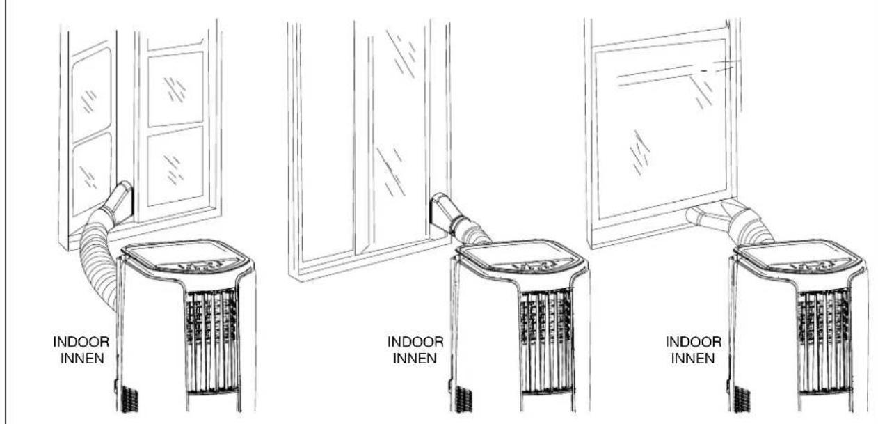
18
19
J
K
L
L3 L2 Direction of hook is upward
natural_image
Technical line drawing of a dual-chamber air conditioning unit with ventilation grilles and wheels (no text or symbols)ENGLISH
WARNING
- DO NOT ingest battery, Chemical Burn Hazard.
- Keep new and used batteries away from children.
- If the battery compartment does not close securely, stop using the product and keep it away from children.
- If you think batteries might have been swallowed or placed inside any part of the body, seek immediate medical attention.
- The batteries contain materials, which are hazardous to the environment; they must be removed from the appliance before it is scrapped and that they are disposed of safely.
- Fuse: 250V, T3,15AH
DEUTSCH
⚠️ WARNHINWEIS
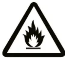
Appliance filled with flammable gas R290.

Before install and use the appli- ance, read the owner's manual first.

Before install the appliance, read the installation manual first.

Before repair the appliance, read the service manual first.
SAFETY TIPS IMPORTANT
- Read instructions carefully before operation.
- The unit should be operated when the room temperature is between 16°C to 35°C. If the room temperature is below 16°C, ice may form on the coils. If the room temperature is above 35°C, the compressor will automatically shut off to protect itself.
- ALWAYS, wait 3 min. to restart after turning unit off.
WARNING
- NEVER expose infants, handicapped persons, or senior persons directly to the airflow. Adjust the airflow direction.
- Keep children away from the unit. Children are particularly liable to this danger. The inside fan is running at high speed. Covering them may deteriorate air conditioner performance or cause it to become inoperative.
- NEVER insert objects of any kind into the air intake or air outlet.
- DO NOT unplug if your hands are wet. An electrical shock may occur.
- DO NOT operate in a wet location.
- The appliance shall be installed in accordance with national wiring regulations.
- ALWAYS plug into 220\~240V, 50Hz, single phase electrical outlet.
-
Be sure the power plug fits the receptacle securely.
-
DO NOT run power cord under carpets, rugs, or floor mats of any kind.
- DO NOT attempt to shorten or alter power cord in any way.
- DO NOT apply any excessive force or pressure to the power supply cord.
- Make sure that the plug is free of dust.
- DO NOT use an extension cord.
- DO NOT turn on and off by inserting or removing the power plug which may cause electric shock or fire.
- If the power cord on this unit is damaged it must be replaced by the manufacturer, its service agent or qualified persons in order to avoid a hazard.
- If there is a fear of lightning, stop the unit and disconnect the power supply cord.
- DO NOT touch the evaporator, condenser and pipes.
- DO NOT operate with filter removed.
- This appliance can be used by children aged from 8 years and above and persons with reduced physical, sensory or mental capabilities or lack of experience and knowledge if they have been given supervision or instruction concerning use of the appliance in a safe way and understand the hazards involved.
• Children shall not play with the appliance. - Cleaning and user maintenance shall not be made by children without supervision.
- Prohibit operating the unit in the bath room or laundry room.
- DO NOT through sundries into the air duct. If there are sundries get into the air duct, please contact the professionals to deal with it.
CAUTION
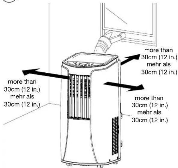
- Keep unit more than 30 cm (12 in) away from any objects or wall. (Fig. G)
-
If the unit is operated in COOL mode in an area of very high moisture, the surface of the unit may get covered with a mist. Wipe off any mist before it has a chance to get on the floor or rug.
-
Remove drain water before moving unit.
- To minimize corrosion, DO NOT use in damp, salty air area.
- DO NOT operate in direct sunlight.
- DO NOT use for such particular purpose as preservation of foodstuff, animals, plants, precision appliances, arts and medicine.
- DO NOT place an animal, plants or combustion equipment in a place which is subjected to the direct air flow of the unit.
- DO NOT ride or place the objects on the unit.
- DO NOT turn the unit on its side or upside down.
The Refrigerant
- To realize the function of the air conditioner unit, a special refrigerant circulates in the system. The used refrigerant is the fluoride R290, which is specially cleaned. The refrigerant is flammable and inodorous. Furthermore, it can leads to explosion under certain conditions.
- Compared to common refrigerants, R290 is a nonpolluting refrigerant with no harm to the ozonosphere. The influence upon the greenhouse effect is also lower. R290 has got very good thermodynamic features which lead to a really high energy efficiency. The units therefore need a less filling.
- Please refer to the nameplate for the charging quantity of R290.
WARNING
- Appliance filled with flammable gas R290.
- Appliance shall be installed, operated and stored in a room with a floor area larger than 11 m² (For TAD-2220E, 2226E) or 15 m² (For TAD-2229E, 2235E).
-
The appliance shall be stored in a room without continuously operating ignition sources. (for example: open flames, an operating gas appliance or an operating electric heater.)
-
The appliance shall be stored in a well-ventilated area where the room size corresponds to the room area as specified for operation.
- The appliance shall be stored so as to prevent mechanical damage from occurring.
- Ducts connected to an appliance shall not contain an ignition source.
- Keep any required ventilation openings clear of obstruction.
- DO NOT pierce or burn.
- Be aware that refrigerants may not contain an odour.
- DO NOT use means to accelerate the defrosting process or to clean, other than those recommended by the manufacturer.
- Servicing shall be performed only as recommended by the manufacturer.
- Should repair be necessary, contact your nearest authorized Service Center. Any repairs carried out by unqualified personnel may be dangerous.
- Compliance with national gas regulations shall be observed.
- Read specialist's manual (See Section 13).


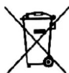
This marking indicates that this product should not be disposed with other household wastes throughout the EU. To prevent ■ possible harm to the environment or human health from uncontrolled waste disposal, recycle it responsibly to promote the sustainable reuse of material resources. To return your used device, please use the return and collection systems or contact the retailer where the product was purchased. They can take this product for environmental safe recycling.
R290: 3
SUMMARY
The idea behind the unit is to provide a localized supply of cool air. The unit will greatly enhance your personal comfort whether at a work station or even in your favorite chair.
Four (4) casters enable you to move the unit easily from room to room. It cools and dries the air at the same time so that you can stay comfortable even when it is humid or rainy outside. Also your furnishings and fabrics are kept in good condition when it is used as dehumidifier.
Conventional air conditioners use large quantities of energy to cool an entire room, including walls and furniture. This unit creates a zone of cool and dry air only where it is needed. It does not waste energy cooling the surroundings.
It is easy to operate. The built-in timer allows from 0.5 to 24 hours of operation, which will automatically turn the unit on and off.
At bedtime, sleep function is convenient. By increasing the preset temperature by slow degrees, you can sleep more comfortable. Venting is not required. However, if the unit is to be used exclusively in one space, the cooling efficiency will be enhanced by using the venting kit accessory, which is included with the unit.
OPERATIONAL FEATURES
Normally, cool air / heat air (For TAD-2235E) is directed out the front louvers by the circulation fan.
2. AUTOMATIC OPERATION:
Once the desired function has been set, it is memorized as long as it remains connected to the wall outlet. In the event of a power failure, the desired function must be re-entered when power is restored.
3. THERMO CONTROL:
The compressor will automatically shift to ON or OFF to maintain the desired temperature.
4. TIMER OPERATION:
The unit will turn on and off after the designated period of time (0.5, 1, 1.5, ....24 hours).
5. AUTOMATIC SHUT-OFF MECHANISM WHEN THE DRAIN TANK IS FULL:
When the chassis is full with water, the unit will be automatically shut off. The buzzer will give out 8 seconds and "H8" is displayed on the remote controller.
6. AIR FILTER:
A pre-filter protects the unit from dust.
1. DESCRIPTION
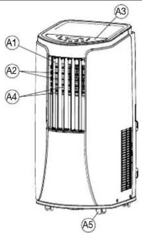
Fig. A FRONT
A1 Air outlet
A2 Horizontal louver
A3 Operation panel
A4 Vertical louver
A5 Caster
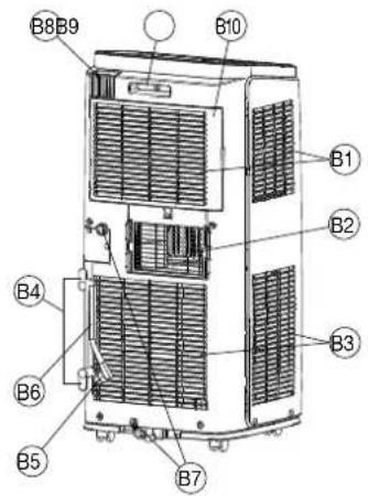
Fig. B REAR
B1 Air intake (Evaporator)
B2 Exhaust outlet
B3 Air intake (Condenser)
B4 Power supply cord hook
B5 Power plug
B6 Power supply cord
B7 Water drainage outlet for continuous drain operation
(Dehumidify and Cool mode)
B8 Remote control holder
B9 Carrying handle
B10 Air intake grille (Pre-filter)
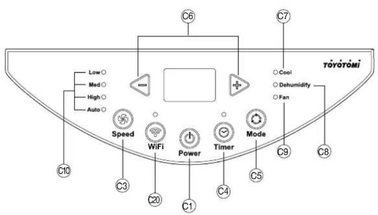
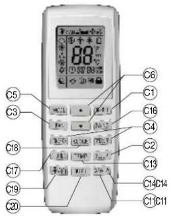
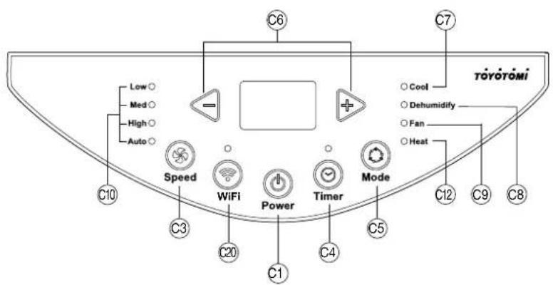
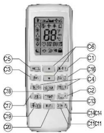
C8 Dehumidify mode lamp
C9 Fan mode lamp
C10 Auto./ High / Med. / Low air flow lamp
C11 X-FAN operation (Internal drying operation) button
C12 Heat mode lamp (For TAD-2235E)
C13 Temperature set button (Not applicable for this unit)
C14 Light button
C15 Health / Save button (Not applicable for this unit)
C16 “■”, “■” and SWING button (Not applicable for this unit)
C17 TURBO button (Not applicable for this unit)
C18 CLOCK button
C19 / button
C20 WiFi button
Indication symbols on remote controller
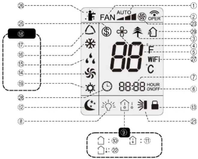
① Set fan mode
② Sending signal
③ (Not applicable for this unit)
④ X-fan operation
(Internal drying operation)
⑤ Set temperature
⑥ ON timer / Off timer
⑦ Set time
⑧ Light
⑨ Temperature display type
⑩ Set temperature
⑪ Indoor ambient temperature
⑫ Sleep mode
⑬ Child lock
⑭ Fan mode
⑮ Dehumidify mode
⑯ Cool mode
⑰ Auto. mode
⑱ Operation mode
⑲ Heat mode (For TAD-2235E)
⑳-⑳(Not applicable for this unit)
⑳ WiFi function
28 Clock
⑲ Ventilation operation
2. OPERATION
OPERATING STEPS:
1. PRESS "POWER" BUTTON (C1) TO "ON".
2. PRESS MODE BUTTON (C5).
Press the mode button (C5) to set your desired operation mode "Cool" (C7), "Dehumidify" (C8), "Fan" (C9) or "Heat" (C12) (For TAD-2235E).
Cool mode (C7)
During the "Cool" mode the air is cooled and hot air is exhausted from the exhaust outlet.
NOTE: During Cool mode, you can adjust set temperature and FAN speed.
Dehumidify mode (C8)
Air is dehumidified as it passes through the unit, without being in full cool mode.
NOTE: In "Dehumidify" mode operation, you cannot change the fan speed.
Fan mode (C9)
The “Fan” mode provides only circulation of room air, so that you cannot set the room temperature.
NOTE: All mode indicators on the unit will be OFF. Fan speed can be adjusted.
Heat mode (C12) (For TAD-2235E)
Under this mode, heating mode indicator is bright. Seven segment display shows set temperature. Temperature setting range is 16°C\~30°C.
3. PRESS TIMER / TEMPERATURE ADJUST BUTTONS (C6)
Press timer button (C4) to enter into timer setting mode. Under this mode, press “+” or “-” button (C6) to adjust the timer setting. Timer setting will increase or decrease 0.5 hour by pressing “+” or “-” button within 10 hours, while timer setting will increase or decrease 1 hour by pressing “+” or “-” button beyond 10 hours.
After timer setting is finished, the unit will display temperature if there is no operation for 5 seconds. The status will be shown on the digital indicator if timer function is started up. Under timer mode, press timer button again to cancel timer mode.
4. PRESS FAN SPEED BUTTON (C3)
Press the fan speed button (C3) to set the desired air flow rate. Under "Dehumidify" mode, this button is invalid.
Auto · · · · · · · Operation at air flow automatically according to ambient temperature
Press the Power button (C1) and all lights will go out.
SLEEP MODE OPERATION (C2)
Press "Sleep" button (C2) to enter into sleep mode. When the unit operates at Cooling mode, preset temperature will increase 1°C by 1 hour. After 2 hours, the unit will keep operation at this temperature all the time.
(For TAD-2235E) If the controller operates at heating mode, after sleep mode is started up, preset temperature will decrease by 1°C within 1 hour; preset temperature will decrease by 2°C within 2 hours and then the unit will operate at this temperature all the time.
NOTE: Sleep function is only for Cool mode and Heat mode (For TAD-2235E), and not available for Fan, Dehumidify, and Auto mode.
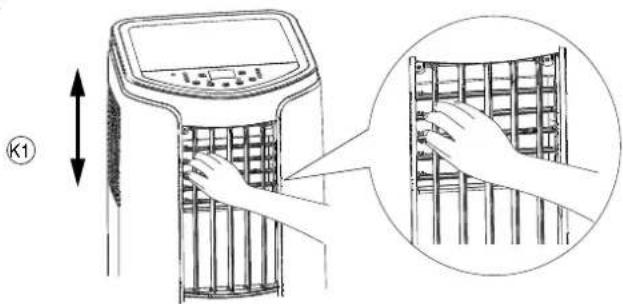
HORIZONTAL ADJUSTABLE LOUVER (A2)
The air outlet can be adjusted upward or downward. (Fig. K1) CAUTION:
Do not adjust the horizontal louvers to the lowest or the highest position during the Cool or Dehumidify mode with the fan speed set to Low for an extended period of time, condensation may form on the louvers.
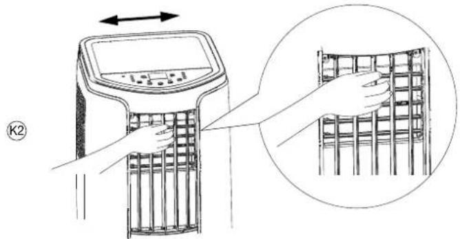
VERTICAL ADJUSTABLE LOUVER (A4)
The air outlet can be adjusted rightward or leftward. (Fig. K2) CAUTION:
Do not adjust the vertical louvers to the extreme left or right during the Cool or Dehudmify mode with the fan speed set to Low for an extended period of time. Condensation may form on the louvers.
REMOTE CONTROL HOLDER (B8)
To prevent the remote control from being misplaced, place remote control to the remote control holder on the unit when not in use.
3. USING REMOTE CONTROL
After putting through the power, the air conditioner will give out a sound. After the operation indicator “☐” is ON (red indicator), you can operate the air conditioner by using remote control. By pressing the button on the remote control, the signal icon “☐” on the display of remote control will blink once and the air conditioner will give out a sound, which means the signal has been sent to the air conditioner.
The functions work the same as your air conditioner's operation panel. (Fig. C)
Set temperature and clock icon will be displayed on the display during the unit OFF.
If you set some function by remote control, the corresponding set icons and light will be shown on the display.
NOTE:
- The interval between two motions cannot exceed 5 seconds, otherwise the remote control will exit setting status.
TIMER / TEMPERATURE ADJUST BUTTON (C6)
Pressing adjust button (C6) once will increase or decrease set temperature by 1°C (°F).
Holding adjust button (C6) for 2 seconds, the set temperature on remote controller will change quickly.
NOTE:
- Under OFF status, pressing “▼” button and “MODE” button simultaneously, you can switch between °C and °F.
• Temperature cannot be adjusted under auto mode.
X-FAN BUTTON (Internal drying operation) (C11)
Press the X-FAN button (C11) or hold fan speed button (C3) for 2 seconds in Cool or Dehumidify mode, the icon "✗" is displayed and the indoor fan will continue operation for a few minutes in order to dry the indoor unit even though you have turned off the unit. After energization, X-FAN OFF is defaulted. X-FAN is not available in Auto or Fan mode. This function indicates that moisture on evaporator of indoor unit will be blown after the unit is stopped to avoid mould.
- Having set X-FAN function on: After turning off the unit by pressing ON/OFF button indoor fan will continue running for a few minutes at low speed. In this period, hold fan speed button for 2 seconds to stop indoor fan directly.
- Having set X-FAN function off: After turning off the unit by pressing ON/OFF button, the complete unit will be off directly.
TIMER BUTTON (C4)
OFF TIMER
Press TIMER OFF button to initiate the auto-off timer. To cancel the auto-timer program, simply press the button again. TIMER OFF setting is the same as TIMER ON.
ON TIMER
Press TIMER ON button to initiate the auto-ON timer. To cancel the auto-timer program, simply press this button again.
After press of this button, ⏻ disappears and "ON" blinks. 00:00 is displayed for ON time setting. Within 5 seconds, press ▲ or ▼ button to adjust the time value. Every press of either button changes the time setting by 1 minute. Holding down either button rapidly changes the time setting by 1 minute and then 10 minutes. Within 5 seconds after setting, press TIMER ON button to confirm.
CHILD LOCK FUNCTION (For remote control)
Press adjust buttons (C6) simultaneously, turn on or turn off child lock function.
Child lock is ON.....“💡” icon on remote control is ON.
If you operate the remote control, remote control will not send signal.
LIGHT BUTTON (C14)
Press "LIGHT" button (C14) to turn off the light for the unit's display. "💡" icon on remote control will disappear. Press LIGHT button again to turn on the light for the unit's display. "💡" icon on remote controller will be displayed.
WIFI BUTTON (C20)
Operation panel: After the unit is powered up, press "WiFi" button (C20) to turn on or off WiFi function. Press and hold the button for 10 seconds to reset WiFi function.
Remote control: Press "WiFi" button (C20) to turn on or turn off WiFi function. When WiFi function is turned on, the "WiFi" icon will be displayed on remote controller; Under status of unit off, press "MODE" button (C5) and "WiFi" button (C20) simultane-
ously for 1 second, WiFi module will restore to factory default setting.
CLOCK BUTTON (C18)
Press CLOCK button (C18), ⏻ blinking. Within 5 seconds, pressing ▲ or ▼ button adjusts the present time. Holding down either button above 2 seconds increases or decreases the time by 1 minute every 0.5 second and then by 10 minutes every 0.5 second. During blinking after setting, press CLOCK button again to confirm the setting, and then ⏻ will be constantly displayed.
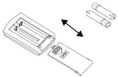
Batteries: Remove the cover on the back of the remote control and insert the batteries with the (+) and (−) poles pointing in the proper direction. (Fig. D)
CAUTION
- Use only AAA or IEC R03 1.5V batteries.
- DO NOT use rechargeable batteries.
- All batteries should be replaced at the same time.
- DO NOT dispose of the batteries in a fire as they may explode.
- DO NOT install the batteries with the polarity (+/-) reversed.
- Keep batteries and other things that could be swallowed away from young children. Contact a doctor immediately if an object is swallowed.
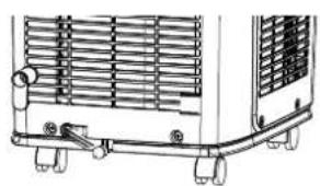
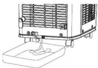
4. DRAINING EXCESS WATER (Fig. E)
- Drain excess water from the chassis by placing a pan under the drain water outlet. (Fig. E2)
- Remove the drain plug, and let the water drain into the pan.
- When the water stops draining out, replace the drain plug.
- Remove the pan of water.
- Operate the unit in Fan mode to dry the interior of the unit. NOTE:
- Remove the drain water from the tank once a week.
- Cooling or drying operation, the condensation water will be drained to the chassis and spattered by water-striking motor. As the temperature of condenser is high, most of the condensation water will be evaporated and drained to outdoor. So usually, only a little condensation water will be accumulated inside the chassis and you do not need to discharge the water frequently.
- When the chassis is full with water, the buzzer will give out 8 sounds and "H8" is displayed to remind user to discharge water:
5. CONTINUOUS DRAINAGE
There are 2 ways to remove collected water:
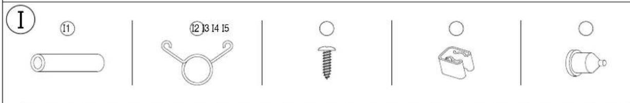
1. DRAINAGE FROM THE BOTTOM HOLE (Fig. I)
NOTE: When using the continuous drainage option from the bottom hole, install drainage pipe before using, otherwise poor drainage will affect normal operation of the unit.
Prepare the below accessory.
I1 Drainage hose
12 Hose band
13
Screw
14 Drainage hose clip
15 Rubber plug
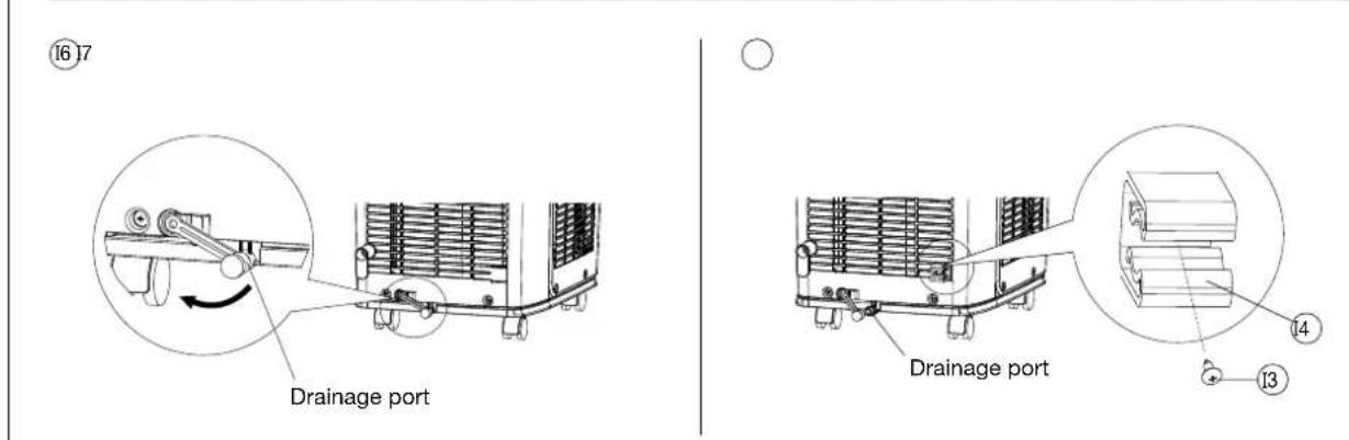
INSTALLATION OF DRAINAGE HOSE CLIP
- Remove the rubber cap at drainage port. (Fig. 16)
- Fix the drainage hose clip (I4) on the right of rear side plate near drainage port with a screw (I3). (Fig. I7)
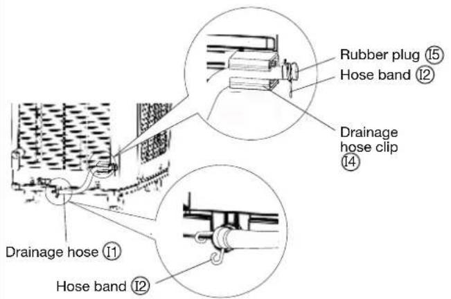
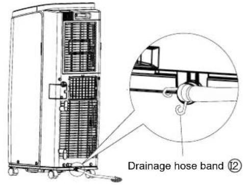
- Put the drainage hose (I1) into drainage port and screw it up, and then bind it with hose band (I2) (Fig. I8)
- Put the rubber plug (I5) into the other side of drainage hose, fix it with hose band (I2) and place it into the drainage hose clip. (Fig. I9)
For continuous drainage, take the drainage hose from the clip and pull out the rubber cap on the drainage hose to discharge water. (Fig. 19)
NOTE:
- After finishing discharging water, put back the rubber cap onto drainage hose and then fix the hose on the clip.
- After full water protection is eliminated and the compressor has been stopped for 3 minutes, the unit will resume operation.
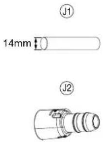
2. DRAINAGE FROM THE MIDDLE HOLE
Prepare the below parts. (Fig. J)
J1 Drainage hose of inner diameter of 14mm (Not included, available in market)
J2 Drain connector
- To drain, remove the drain cap (J3) by turning it counter clockwise then remove the rubber stopper (J4) from the spout. (Fig. J5)
- Screw the drain connector (J2) to the spout by turning clockwise. (Fig. J6)
- Insert the drainage hose (J1) into drain connector horizontally below the drainage hole.
Avoid uneven ground and folding the hose. (Fig. J7)
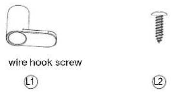
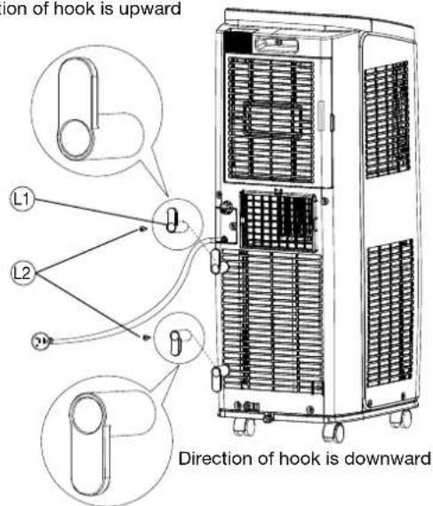
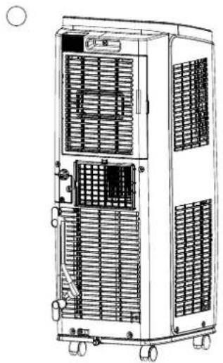
6. INSTALLATION OF POWER SUPPLY CORD HOOK (Fig. L)
Assemble the power supply cord hook (L1) at the back of the unit with screws (L2). (Fig L3) The direction of upper hook is upward. For lower hook, direction is downward.
Wind the power supply cord around the wire hook. (Fig. L4)
7. CLEANING
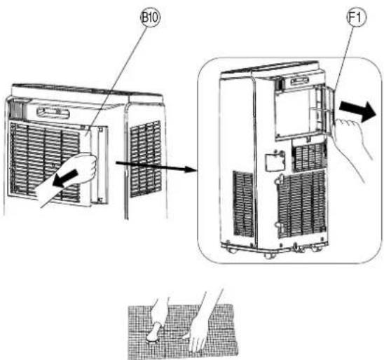
CLEANING AIR INTAKE GRILLE (Fig. F)
- Clean the air intake grille (B10) once every two weeks.
- To remove the outside air intake filter (B10) pull the filter off by pressing the clasp which is on the filter. (Fig. F1)
- Remove the dust with a vacuum cleaner.
WARNING
- DO NOT touch the evaporator. It may cause injury or damage.
CLEANING SURFACE
Clean the outside of the unit with a soft damp cloth.
CAUTION
- NEVER use gasoline, solvents, chemical, products or polish as they could damage the surface.
- Before cleaning the air conditioner, please turn off the unit and disconnect power. Otherwise, it may cause electric shock.
- DO NOT wash air conditioner with water. Otherwise, it may cause electric shock.
- Remove the drain water from the chassis and unplug the unit.
8. LONG-TERM STORAGE
At the end of each season, or when you do not plan to use your unit for an extended period of time, the following procedures are recommended.
- Run the unit 5 or 6 hours with only the "Fan" mode operating in order to dry the inside.
- Remove the drain water from the chassis and unplug the unit.
- Clean the unit.
Wipe off any dirt or dust on the unit with a soft damp cloth or a vacuum cleaner, and then wipe again using a soft dry cloth. - Clean the air intake grille (B10) and replace it.
- Store the unit.
The original shipping carton is the best place to store your unit. If you do not have the original packing materials, cover the unit with a large plastic bag and store in a cool dry place.
CAUTION
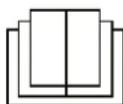
- ALWAYS store the unit in the vertical position.
- DO NOT put heavy objects on top of the unit.
9. TRANSPORTATION
Preferably keep the unit in the vertical position during transportation. If it is necessary to place the unit in a horizontal position more than 1/2 hour, ALLOW IT TO REMAIN UPRIGHT FOR 24 HOURS BEFORE OPERATION. Failure to do so may result in damage to the compressor. Before transporting / moving the unit make sure the drain tank is empty.
10. TROUBLE SHOOTING
Check the following before contacting technical support:
| Problem Cause Solution | ||
| Air conditioner does not operate. | - Power failure.- Power plug is loose.- The air switch is tripped off or fuse is burnt.- Malfunction of the circuit.- The unit is restarted up after stopping immediately. | - Wait after power recovery.- Reinsert the plug.- Ask professional person to replace air switch or fuse.- Ask professional person to replace circuit.- Wait for 3 minutes, and then turn on the unit again. |
| Unit functions but the room is not cooled. | - The power is too low.- The air filter is too dirty.- The set temperature is not proper.- Door and window are closed. | - Wait after voltage is resumed.- Clean the air filter.- Adjust the temperature.- Close door and window. |
| Air conditioner cannot receive signal from remote controller or remote controller is not sensible. | - The unit is interfered seriously such as static pressure, unstable voltage.- The remote control is not within the receiving range.- The unit is blocked by obstacles.- The sensitivity of remote control low.- There is fluorescence lamp in the room. | - Please pull out the plug. Insert the plug after about 3 minutes, and then turn on the unit.- The receiving range of remote controller is 8 m. Do not exceed this range.- Remove the obstacles.- Check the batteries of remote control. If the power is low, please replace the batteries.- Move the remote control close to air conditioner.- Turn off the fluorescence lamp and try it again. |
| No fan blew out from air Conditioner. | - The air outlet or air inlet is blocked.- Evaporator is defrosted.(Observe it by pulling out the filter.) | - Eliminate the obstacles.- It is the normal phenomenon. Air conditioner is defrosting. After defrosting is finished, it will resume operation. |
| Set temperature can't be adjusted. | - The unit operates under auto mode.- The required temperature exceeds the temperature setting range. | - Temperature cannot be adjusted under auto mode.- Adjust the temperature setting between 16^ - 30^ . |
BEFORE CALLING FOR SERVICE
The following are not defects.
| A hissing noise or hollow sound: | ⇒ | This sound is generated from the refrigerant flowing within pipes. |
| A squeaking noise: | ⇒ | This noise is generated from the unit when it is expands or contracts with temperature changes. |
| Odor: | ⇒ | Such odor as tobacco, cosmetics, or foods may accumulate in the unit. |
| The unit does not start nor change operation mode immediately: | ⇒ | To prevent overloading the compressor motor, the unit will be stopped for more than 3 minutes. |
MALFUNCTION ANALYSIS
Malfunction code
| H8 | Tank is full of water. 1. Po | our out the water inside tank.2. If “H8” still exists, please contact professional person to maintain the unit. |
| F1 | Malfunction of ambient temperature sensor. | Please contact professional person to deal with it. |
| F2 | Malfunction of evaporator temperature sensor. | Please contact professional person to deal with it. |
| F0 | 1. Refrigerant is leaking.2. System is blocked. | Please contact professional person to deal with it. |
| H3 | Overload protection for compressor. | 1. If ambient temperature is too high, power off the unit and then energize it for operation after the ambient temperature drops to below 35°.2. Check if the evaporator and condenser are blocked by some objects. If yes, take away the objects, power off the unit and then energize it for operation.3. If the malfunction still occur please contact our after-sales service center. |
| E8 | Overload malfunction. | |
| F4 | Outdoor tube temperature sensor is open/short-circuited. |
11. SPECIFICATIONS
| MODEL TAD-2220E | TAD-2226E TAD-2229E TAD-2235E | |||
| POWER SOURCE | Single Phase 220~240 V, 50 Hz | Single Phase 220~240 V, 50 Hz | Single Phase 220~240 V, 50 Hz | Single Phase 220~240 V, 50 Hz |
| COOLING CAPACITY | 2,0 kW (6.824 BTU) | 2,6 kW (8.871 BTU) | 2,9 kW (9.895 BTU) | 3,5 kW (11.942 BTU) |
| COOLING POWER INPUT | 765 W | 1.000 W | 935 W | 1.345 W |
| HEATING CAPACITY | - | - | - | 3,0 kW (10.236 BTU) |
| HEATING POWER INPUT | - | - | - | 1.150 W |
| EE Class / EER* | A / 2,60 | A / 2,60 | A+ / 3,10 | A / 2,60 |
| EE Class / COP* | - | - | - | A+ / 2,60 |
| POWER CONSUMPTION IN STANDBY MODE | 0,5 W | 0,5 W | 0,5 W | 0,5 W |
| DEHUMIDIFYING CAPACITY | 1,0 L/h | 1,43 L/h | 1,60 L/h | 1,80 L/h |
| OPERATING CURRENT | 3,6 A | 4,5 A | 4,1 A | 5,9 A / 5,0 A (Cooling/ Heating) |
| AIR FLOW (MAX.) | 300 m3/h | 320 m3/h | 360 m3/h | 360 m3/h |
| FOR ROOMS UP TO | 10 - 16 m2 | 12 - 17 m2 | 13 - 19 m2 | 15 - 22 m2 |
| OPERATING TEMP. RANGE | 16~35°C | 16~35°C | 16~35°C | 16°C~35°C / 10°C~27°C (Cooling / Heating) |
| SOUND POWER LEVEL | 63 dB | 63 dB | 64 dB | 65 dB |
| UNIT PROTECTION | IPXO | IPXO | IPXO | IPXO |
| FUSE RATING | 3,15 A | 3,15 A | 3,15 A | 3,15 A |
| DIMENTIONS (W×H×D) | 315×770×395 mm | 315×770×395 mm | 390×820×405 mm | 390×820×405 mm |
| WEIGHT | 22,5 kg | 25,5 kg | 32,0 kg | 35,0 kg |
| COMPRESSOR | ROTARY | ROTARY | ROTARY | ROTARY |
| REFRIGERANT | R290 / 0,13 kg | R290 / 0,18 kg | R290 / 0,22 kg | R290 / 0,24 kg |
| GWP | 3 | 3 | 3 | 3 |
*Confirm to EN-14511: 2018
NOTE: Cooling air capacity will vary according to temperature and humidity of the room.
Frequency band(s) in which the radio equipment operates: 2400MHz-2483.5MHz
Maximum radio-frequency power transmitted in the frequency band(s) in which the radio equipment operates: 20dBm
12. VENTING KIT ACCESSORIES
If the unit is to be used exclusively in one space, the cooling efficiency will be enhanced by using the following venting kit accessories.
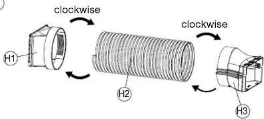
USING EXHAUST DUCT SET (Fig. H)
- Prepare the below accessory.
H1 Exhaust duct hose adapter nozzle (Fix to unit) H2 Exhaust duct hose
H3 Exhaust nozzle (upper) + Exhaust nozzle (lower)
-
To fix the Exhaust nozzle (upper) and the Exhaust nozzle (lower) together, press the clasp forcibly into the groove. (Fig. H4)
-
Insert one end of exhaust duct hose (flexible tube) (H2) into exhaust duct hose adapter nozzle (H1) by turning it counter clockwise. And install exhaust nozzle (upper + lower) (H3) into another side of exhaust duct hose. (Fig. H5)
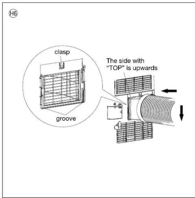
-
Face the side with "TOP" upwards. Insert exhaust duct hose adapter nozzle into the groove of exhaust outlet until you hear a sound. (Fig. H6)
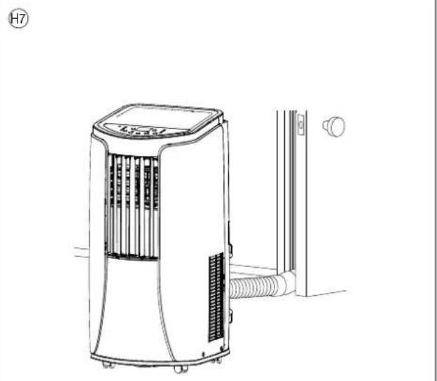
-
Place the exhaust hose outdoors. (Fig. H7)
NOTE: Place the unit as close as possible to the window or door. (H5, H6, H7)
13. Specialist's Manual
Aptitude requirement for maintenance man(repairs should be done only be specialists).
a. All the work men who are engaging in the refrigeration system should bear the valid certification awarded by the authoritative organization and the qualification for dealing with the refrigeration system recognized by this industry.
b. It can only be repaired by the method suggested by the equipment's manufacturer.
If it needs other technician to maintain and repair the appliance, they should be supervised by the person who bears the qualification for using the flammable refrigerant.
Safety preparation work before installation
The safety must be inspected before maintaining the appliances with the flammable refrigerant for reducing the flammable hazard to the lowest.
Work shall be undertaken under a controlled procedure so as to minimise the risk of a flammable gas or vapour being present while the work is being performed.
Detection of flammable refrigerants
Under no circumstances shall potential sources of ignition be used in the searching for or detection of refrigerant leaks. A halide torch (or any other detector using a naked flame) shall not be used.
Environment checking
- All maintenance staff and others working in the local area shall be instructed on the nature of work being carried out. Work in confined spaces shall be avoided. The area around the workspace shall be sectioned off. Ensure that the conditions within the area have been made safe by control of flammable material.
- The area shall be checked with an appropriate refrigerant detector prior to and during work, to ensure the technician is aware of potentially toxic or flammable atmospheres.
Ensure that the leak detection equipment being used is suitable for use with all applicable refrigerants, i.e. non-sparking, adequately sealed or intrinsically safe.
- No person carrying out work in relation to a refrigeration system which involves exposing any pipe work shall use any sources of ignition in such a manner that it may lead to the risk of fire or explosion. All possible ignition sources, including cigarette smoking, should be kept sufficiently far away from the site of installation, repairing, removing and disposal, during which refrigerant can possibly be released to the surrounding space. Prior to work taking place, the area around the equipment is to be surveyed to make sure that there are no flammable hazards or ignition risks. "No Smoking" signs shall be displayed.
- If any hot work is to be conducted on the refrigeration equipment or any associated parts, appropriate fire extinguishing equipment shall be available to hand. Have a dry powder or CO_2 fire extinguisher adjacent to the charging area.
- Ensure that the area is in the open or that it is adequately venti-
lated before breaking into the system or conducting any hot work. A degree of ventilation shall continue during the period that the work is carried out. The ventilation should safely disperse any released refrigerant and preferably expel it externally into the atmosphere.
Refrigeration equipment Checking
Where electrical components are being changed, they shall be fit for the purpose and to the correct specification. At all times the manufacturer's maintenance and service guidelines shall be followed. If in doubt, consult the manufacturer's technical department for assistance.
The following checks shall be applied to installations using flammable refrigerants:
- The actual refrigerant charge is in accordance with the room size within which the refrigerant containing parts are installed;
- The ventilation machinery and outlets are operating adequately and are not obstructed;
- If an indirect refrigerating circuit is being used, the secondary circuit shall be checked for the presence of refrigerant;
- Marking to the equipment continues to be visible and legible. Markings and signs that are illegible shall be corrected;
- Refrigeration pipe or components are installed in a position where they are unlikely to be exposed to any substance which may corrode refrigerant containing components, unless the components are constructed of materials which are inherently resistant to being corroded or are suitably protected against being so corroded.
Electrical devices checking
Repair and maintenance to electrical components shall include initial safety checks and component inspection procedures. If a fault exists that could compromise safety, then no electrical supply shall be connected to the circuit until it is satisfactorily dealt with. If the fault cannot be corrected immediately but it is necessary to continue operation, an adequate temporary solution shall be used. This shall be reported to the owner of the equipment so all parties are advised.
Initial safety checks shall include:
- That capacitors are discharged: this shall be done in a safe manner to avoid possibility of sparking;
- That no live electrical components and wiring are exposed while charging, recovering or purging the system;
- That there is continuity of earth bonding.
Repairs to sealed components
During repairs to sealed components, all electrical supplies shall be disconnected from the equipment being worked upon prior to any removal of sealed covers, etc. If it is absolutely necessary to have an electrical supply to equipment during servicing, then a permanently operating form of leak detection shall be located at the most critical point to warn of a potentially hazardous situation. Particular attention shall be paid to the following to ensure that by working on electrical components, the casing is not altered in such a way that the level of protection is affected.
This shall include damage to cables, excessive number of connections, terminals not made to original specification, damage to seals, incorrect fitting of glands, etc.
- Ensure that the apparatus is mounted securely.
- Ensure that seals or sealing materials have not degraded to the point that they no longer serve the purpose of preventing the ingress of flammable atmospheres. Replacement parts shall be in accordance with the manufacturer's specifications.
NOTE : The use of silicon sealant can inhibit the effectiveness of some types of leak detection equipment. Intrinsically safe components do not have to be isolated prior to working on them.
Cabling
Check that cabling will not be subject to wear, corrosion, excessive pressure, vibration, sharp edges or any other adverse environmental effects. The check shall also take into account the effects of aging or continual vibration from sources such as compressors or fans.
Leak detection methods
The following leak detection methods are deemed acceptable for all refrigerant systems.
Electronic leak detectors may be used to detect refrigerant leaks but, in the case of flammable refrigerants, the sensitivity may not be adequate, or may need re-calibration.
(Detection equipment shall be calibrated in a refrigerant-free area.) Ensure that the detector is not a potential source of ignition and is suitable for the refrigerant used.
Leak detection equipment shall be set at a percentage of the LFL
of the refrigerant and shall be calibrated to the refrigerant employed, and the appropriate percentage of gas (25 % maximum) is confirmed.
Leak detection fluids are suitable for use with most refrigerants but the use of detergents containing chlorine shall be avoided as the chlorine may react with the refrigerant and corrode the copper pipe-work.
If a leak is suspected, all naked flames shall be removed/extinguished.
If a leakage of refrigerant is found which requires brazing, all of the refrigerant shall be recovered from the system, or isolated (by means of shut off valves) in a part of the system remote from the leak. For appliances containing flammable refrigerants, oxygen free nitrogen (OFN) shall then be purged through the system both before and during the brazing process.
Removal and evacuation
When breaking into the refrigerant circuit to make repairs – or for any other purpose – conventional procedures shall be used. However, for flammable refrigerants it is important that best practice is followed since flammability is a consideration. The following procedure shall be adhered to:
- remove refrigerant;
• purge the circuit with inert gas; - evacuate;
• purge again with inert gas; - open the circuit by cutting or brazing.
The refrigerant charge shall be recovered into the correct recovery cylinders.
For appliances containing flammable refrigerants, the system shall be “flushed” with OFN to render the unit safe. This process may need to be repeated several times.
Compressed air or oxygen shall not be used for purging refrigerant systems.
For appliances containing flammable refrigerants, flushing shall be achieved by breaking the vacuum in the system with OFN and continuing to fill until the working pressure is achieved, then venting to atmosphere, and finally pulling down to a vacuum.
This process shall be repeated until no refrigerant is within the system.
When the final OFN charge is used, the system shall be vented down to atmospheric pressure to enable work to take place. This operation is absolutely vital if brazing operations on the pipe-work are to take place.
Ensure that the outlet for the vacuum pump is not close to any ignition sources and that ventilation is available.
Charging procedures
In addition to conventional charging procedures, the following requirements shall be followed.
- Ensure that contamination of different refrigerants does not occur when using charging equipment. Hoses or lines shall be as short as possible to minimise the amount of refrigerant contained in them.
– Cylinders shall be kept upright.
- Ensure that the refrigeration system is earthed prior to charging the system with refrigerant.
- Label the system when charging is complete (if not already).
- Extreme care shall be taken not to overfill the refrigeration system.
Prior to recharging the system, it shall be pressure-tested with the appropriate purging gas.
The system shall be leak-tested on completion of charging but prior to commissioning.
A follow up leak test shall be carried out prior to leaving the site.
Decommissioning
Before carrying out this procedure, it is essential that the technician is completely familiar with the equipment and all its detail. It is recommended good practice that all refrigerants are recovered safely. Prior to the task being carried out, an oil and refrigerant sample shall be taken in case analysis is required prior to re-use of reclaimed refrigerant.
It is essential that electrical power is available before the task is commenced.
a) Become familiar with the equipment and its operation.
b) Isolate system electrically.
c) Before attempting the procedure, ensure that:
- mechanical handling equipment is available, if required, for handling refrigerant cylinders;
- all personal protective equipment is available and being used
correctly;
- the recovery process is supervised at all times by a competent person;
- recovery equipment and cylinders conform to the appropriate standards.
d) Pump down refrigerant system, if possible.
e) If a vacuum is not possible, make a manifold so that refrigerant can be removed from various parts of the system.
f) Make sure that cylinder is situated on the scales before recovery takes place.
g) Start the recovery machine and operate in accordance with manufacturer's instructions.
h) Do not overfill cylinders. (No more than 80 % volume liquid charge).
i) Do not exceed the maximum working pressure of the cylinder, even temporarily.
j) When the cylinders have been filled correctly and the process completed, make sure that the cylinders and the equipment are removed from site promptly and all isolation valves on the equipment are closed off.
k) Recovered refrigerant shall not be charged into another refrigeration system unless it has been cleaned and checked.
Labelling
Equipment shall be labelled stating that it has been de-commissioned and emptied of refrigerant. The label shall be dated and signed. For appliances containing flammable refrigerants, ensure that there are labels on the equipment stating the equipment contains flammable refrigerant.
Recovery
When removing refrigerant from a system, either for servicing or decommissioning, it is recommended good practice that all refrigerants are removed safely.
When transferring refrigerant into cylinders, ensure that only appropriate refrigerant recovery cylinders are employed. Ensure that the correct number of cylinders for holding the total system charge are available. All cylinders to be used are designated for the recovered refrigerant and labelled for that refrigerant (i.e. special cylinders for the recovery of refrigerant). Cylinders shall be complete with pressure-relief valve and associated shut-off valves in good working order. Empty recovery cylinders are evacuated and, if possible, cooled before recovery occurs.
The recovery equipment shall be in good working order with a set of instructions concerning the equipment that is at hand and shall be suitable for the recovery of all appropriate refrigerants including, when applicable, flammable refrigerants. In addition, a set of calibrated weighing scales shall be available and in good working order. Hoses shall be complete with leak-free disconnect couplings and in good condition. Before using the recovery machine, check that it is in satisfactory working order, has been properly maintained and that any associated electrical components are sealed to prevent ignition in the event of a refrigerant release. Consult manufacturer if in doubt.
The recovered refrigerant shall be returned to the refrigerant supplier in the correct recovery cylinder, and the relevant waste transfer note arranged. Do not mix refrigerants in recovery units and especially not in cylinders.
If compressors or compressor oils are to be removed, ensure that they have been evacuated to an acceptable level to make certain that flammable refrigerant does not remain within the lubricant. The evacuation process shall be carried out prior to returning the compressor to the suppliers. Only electric heating to the compressor body shall be employed to accelerate this process. When oil is drained from a system, it shall be carried out safely.
LIMITED WARRANTY
TOYOTOMI CO., LTD. ("TOYOTOMI") warrants each product and any parts thereof sold by it to be free from defects in materials or workmanship under normal use and service for TWENTY FOUR (24) MONTHS from the date of delivery to the original purchaser at retail subject to the following terms and conditions:
WHAT IS COVERED : Product or any parts thereof which are defective in materials or workmanship.
WHAT IS NOT COVERED :
This warranty does not extend to any defect due to the negligence of others; failure to install, operate or maintain unit in accordance with instructions (operating and maintenance instructions are furnished with each new unit); unreasonable use, accidents, alteration, use of unauthorized or non-standardized TOYOTOMI parts and accessories; electrical malfunction, i.e., as resulting from large power surges, short circuit, etc.; incorrect installation; or repair by anyone other than a service facility specified by TOYOTOMI.
WHO IS COVERED : The original purchaser at retail.
WHAT WE WILL DO : TOYOTOMI will either repair or replace, at its option, all defective parts free of charge that are covered by this limited warranty on a carry-in basis, to your nearest authorized dealer or distributor of TOYOTOMI.
WHAT YOU MUST DO FOR WARRANTY SERVICE : You must return the defective Product or part to any authorized dealer or distributor of TOYOTOMI with this LIMITED WARRANTY. If service is not available locally, please contact our CUSTOMER RELATIONS DEPARTMENT at :
TOYOTOMI EUROPE SALES B.V.
E-MAIL: info@toyotomi.eu
THE FOREGOING EXPRESSES ALL OF TOYOTOMI'S OBLIGATIONS AND LIABILITIES WITH RESPECT TO THE QUALITY OF PRODUCT FURNISHED BY IT. ALL OTHER WARRANTIES, EXPRESSED OR IMPLIED, INCLUDING THE WARRANTIES OF MERCHANTABILITY OR FITNESS FOR A PARTICULAR PURPOSE ARE DISCLAIMED. TOYOTOMI SHALL NOT BE LIABLE FOR THE LOSS OF USE OF THE PRODUCT, INCONVENIENCE, LOSS OR ANY OTHER DAMAGES, DIRECT OR CONSEQUENTIAL ARISING OUT OF, THE USE OF, OR INABILITY TO USE, THE PRODUCT OR DAMAGES RESULTING FROM OR ATTRIBUTABLE TO DEFECTS IN THE PRODUCT.
No other than TOYOTOMI has authority to extend or modify the terms of this Limited Warranty in any manner whatsoever.
Some states do not allow the exclusion or limitation of incidental or consequential damages or limitations on how long an implied warranty lasts, so these limitations or exclusions may not apply to you. This Limited Warranty gives you specific legal rights and you may also have other rights which vary from state to state.
EXPLICATION DES SYMBOLES


INCLUS DANS LA GARANTIE:


WERKING IN SLAAPMODUS (C2)
4. OVERTOLLIG WATER AFVOEREN (Afb. E)
2. AFVOER VIA DE MIDDENOPENING


1. DRIFT MED K∅LING/OPVARMNING (for TAD-2235E):


WYKLUCZENIA Z GWARANCJI:
- ENGLISH
- WARNING
- DEUTSCH
- ⚠️ WARNHINWEIS
- SAFETY TIPS IMPORTANT
- CAUTION
- The Refrigerant
- SUMMARY
- OPERATIONAL FEATURES
- AUTOMATIC OPERATION:
- THERMO CONTROL:
- TIMER OPERATION:
- AUTOMATIC SHUT-OFF MECHANISM WHEN THE DRAIN TANK IS FULL:
- AIR FILTER:
- DESCRIPTION
- Fig. A FRONT
- Fig. B REAR
- OPERATION
- OPERATING STEPS:
- PRESS "POWER" BUTTON (C1) TO "ON".
- PRESS MODE BUTTON (C5).
- Cool mode (C7)
- Dehumidify mode (C8)
- Fan mode (C9)
- Heat mode (C12) (For TAD-2235E)
- PRESS TIMER / TEMPERATURE ADJUST BUTTONS (C6)
- PRESS FAN SPEED BUTTON (C3)
- SLEEP MODE OPERATION (C2)
- HORIZONTAL ADJUSTABLE LOUVER (A2)
- VERTICAL ADJUSTABLE LOUVER (A4)
- REMOTE CONTROL HOLDER (B8)
- USING REMOTE CONTROL
- TIMER / TEMPERATURE ADJUST BUTTON (C6)
- X-FAN BUTTON (Internal drying operation) (C11)
- TIMER BUTTON (C4)
- OFF TIMER
- ON TIMER
- CHILD LOCK FUNCTION (For remote control)
- LIGHT BUTTON (C14)
- WIFI BUTTON (C20)
- CLOCK BUTTON (C18)
- DRAINING EXCESS WATER (Fig. E)
- CONTINUOUS DRAINAGE
- DRAINAGE FROM THE BOTTOM HOLE (Fig. I)
- INSTALLATION OF DRAINAGE HOSE CLIP
- NOTE:
- DRAINAGE FROM THE MIDDLE HOLE
- INSTALLATION OF POWER SUPPLY CORD HOOK (Fig. L)
- CLEANING
- CLEANING AIR INTAKE GRILLE (Fig. F)
- CLEANING SURFACE
- LONG-TERM STORAGE
- TRANSPORTATION
- TROUBLE SHOOTING
- BEFORE CALLING FOR SERVICE
- MALFUNCTION ANALYSIS
- SPECIFICATIONS
- VENTING KIT ACCESSORIES
- USING EXHAUST DUCT SET (Fig. H)
- Specialist's Manual
- Safety preparation work before installation
- Refrigeration equipment Checking
- Electrical devices checking
- Repairs to sealed components
- Cabling
- Leak detection methods
- Removal and evacuation
- Charging procedures
- Decommissioning
- Labelling
- Recovery
- LIMITED WARRANTY
- WHAT IS NOT COVERED :
- TOYOTOMI EUROPE SALES B.V.
- EXPLICATION DES SYMBOLES
- INCLUS DANS LA GARANTIE:
- WERKING IN SLAAPMODUS (C2)
- OVERTOLLIG WATER AFVOEREN (Afb. E)
- AFVOER VIA DE MIDDENOPENING
- DRIFT MED K∅LING/OPVARMNING (for TAD-2235E):
- WYKLUCZENIA Z GWARANCJI:
Brand : Toyotomi
Model : TAD2229E
Category : Air Conditioning