
Z270M Pro4 - Motherboard ASROCK - Free user manual and instructions
Find the device manual for free Z270M Pro4 ASROCK in PDF.

| Brand | ASRock |
| Model | Z270M Pro4 |
| Type | Motherboard |
| Form Factor | Micro ATX (24.4 cm x 24.4 cm) |
| Socket | LGA 1151 |
| Chipset | Intel® Z270 |
| Supported Processors | Intel® Core™ i7/i5/i3/Pentium®/Celeron® (7th and 6th generations) |
| Memory | DDR4, 4 DIMM slots, max 64 GB, up to 3600+ MHz (OC) |
| Expansion Slots | 2 x PCIe 3.0 x16 (x16/x4), 2 x PCIe 3.0 x1 |
| Storage | 6 x SATA3 6 Gb/s, 2 x Ultra M.2 (PCIe Gen3 x4 and SATA) |
| Graphics | Intel HD Graphics, outputs D-Sub, DVI-D, HDMI (4K supported) |
| Audio | Realtek ALC892, 7.1 HD channels |
| Network | Gigabit LAN Intel I219V |
| Rear Connectivity | 1x PS/2 keyboard, 1x PS/2 mouse, 1x D-Sub, 1x DVI-D, 1x HDMI, 1x USB 2.0, 4x USB 3.0 Type-A, 1x USB 3.0 Type-C, 1x RJ-45, audio jacks |
| Power Supply | ATX 24-pin + 12V 8-pin |
| BIOS | UEFI AMI with multilingual graphical interface |
| Operating Systems | Windows 10 64-bit, 8.1 64-bit, 7 32/64-bit |
| Dimensions | 24.4 cm x 24.4 cm |
| Weight | Approximately 0.5 kg |
| Special Features | AMD CrossFireX, Intel Optane Memory ready, complete protection (spike, ESD) |
| Maintenance | Clean with compressed air, avoid moisture and direct contact |
| Safety | Follow ESD precautions, handle without static electricity |
| Certifications | FCC, CE, WHQL, RCM, BSMI, ErP/EuP |
Frequently Asked Questions - Z270M Pro4 ASROCK
User questions about Z270M Pro4 ASROCK
0 question about this device. Answer the ones you know or ask your own.
Ask a new question about this device
Download the instructions for your Motherboard in PDF format for free! Find your manual Z270M Pro4 - ASROCK and take your electronic device back in hand. On this page are published all the documents necessary for the use of your device. Z270M Pro4 by ASROCK.
USER MANUAL Z270M Pro4 ASROCK
Published October 2016
Copyright©2016 ASRock INC. All rights reserved.
Copyright Notice:
No part of this documentation may be reproduced, transcribed, transmitted, or translated in any language, in any form or by any means, except duplication of documentation by the purchaser for backup purpose, without written consent of ASRock Inc.
Products and corporate names appearing in this documentation may or may not be registered trademarks or copyrights of their respective companies, and are used only for identification or explanation and to the owners' benefit, without intent to infringe.
Disclaimer:
Specifications and information contained in this documentation are furnished for informational use only and subject to change without notice, and should not be constructed as a commitment by ASRock. ASRock assumes no responsibility for any errors or omissions that may appear in this documentation.
With respect to the contents of this documentation, ASRock does not provide warranty of any kind, either expressed or implied, including but not limited to the implied warranties or conditions of merchantability or fitness for a particular purpose.
In no event shall ASRock, its directors, officers, employees, or agents be liable for any indirect, special, incidental, or consequential damages (including damages for loss of profits, loss of business, loss of data, interruption of business and the like), even if ASRock has been advised of the possibility of such damages arising from any defect or error in the documentation or product.

This device complies with Part 15 of the FCC Rules. Operation is subject to the following two conditions:
(1) this device may not cause harmful interference, and
(2) this device must accept any interference received, including interference that may cause undesired operation.
CALIFORNIA, USA ONLY
The Lithium battery adopted on this motherboard contains Perchlorate, a toxic substance controlled in Perchlorate Best Management Practices (BMP) regulations passed by the California Legislature. When you discard the Lithium battery in California, USA, please follow the related regulations in advance.
"Perchlorate Material-special handling may apply, see www.dtsc.ca.gov/hazardouswaste/perchlorate"
ASRock Website: http://www.asrock.com

AUSTRALIA ONLY
Our goods come with guarantees that cannot be excluded under the Australian Consumer Law. You are entitled to a replacement or refund for a major failure and compensation for any other reasonably foreseeable loss or damage caused by our goods. You are also entitled to have the goods repaired or replaced if the goods fail to be of acceptable quality and the failure does not amount to a major failure. If you require assistance please call ASRock Tel: +886-2-28965588 ext.123 (Standard International call charges apply)
The terms HDMI and HDMI High-Definition Multimedia Interface, and the HDMI logo are trademarks or registered trademarks of HDMI Licensing LLC in the United States and other countries.

HIGR-DEFINITION MULTIMEDIA INTERFACE
Motherboard Layout
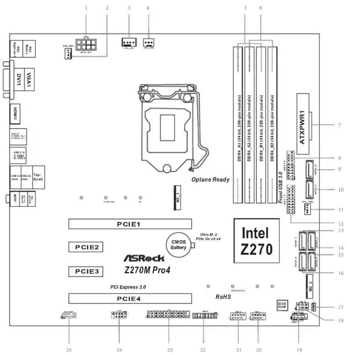
No. Description
1 ATX 12V Power Connector (ATX12V1)
2 Chassis Fan Connector (CHA_FAN1)
3 CPU Fan Connector (CPU_FAN1)
4 CPU Fan Connector (CPU_FAN2)
5 2 x 288-pin DDR4 DIMM Slots (DDR4_A1, DDR4_B1)
6 2 x 288-pin DDR4 DIMM Slots (DDR4_A2, DDR4_B2)
7 ATX Power Connector (ATXPWR1)
8 USB 3.0 Header (USB3_5_6)
9 SATA3 Connector (SATA3_0)
10 SATA3 Connector (SATA3_1)
11 Chassis Fan Connector (CHA_FAN2)
12 USB 3.0 Header (USB3_7_8)
13 SATA3 Connector (SATA3_2)
14 SATA3 Connector (SATA3_3)
15 SATA3 Connector (SATA3_5)
16 SATA3 Connector (SATA3_4)
17 Clear CMOS Jumper (CLRMOS1)
18 Chassis Intrusion and Speaker Header (SPK_C11)
19 System Panel Header (PANEL1)
20 USB 2.0 Header (USB5_6)
21 USB 2.0 Header (USB3_4)
22 TPM Header (TPMS1)
23 Print Port Header (LPT1)
24 COM Port Header (COM1)
25 Front Panel Audio Header (HD_AUDIO1)
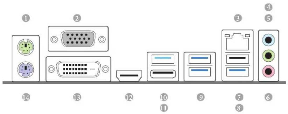
I/O Panel
No. Description No. Description
1 PS/2 Mouse Port 8 USB 3.0 Port (USB2)
2 D-Sub Port 9 USB 3.0 Ports (USB3_3_4)
3 LAN RJ-45 Port 10 USB 3.0 Type-A Port (USB3_TA_1)
4 Line In (Light Blue) 11 USB 3.0 Type-C Port (USB3_TC_1)
5 Front Speaker (Lime)** 12 HDMI Port
6 Microphone (Pink)* 13 DVI-D Port
7 USB 2.0 Port (USB1) 14 PS/2 Keyboard Port
- There are two LEDs on the LAN port. Please refer to the table below for the LAN port LED indications.
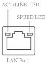
| Activity / Link LED | |
| Status | Description |
| Off | No Link |
| Blinking | Data Activity |
| On | Link |
| Speed LED | |
| Status | Description |
| Off | 10Mbps connection |
| Orange | 100Mbps connection |
| Green | 1Gbps connection |
To configure 7.1 CH HD Audio, it is required to use an HD front panel audio module and enable the multichannel audio feature through the audio driver.
Please set Speaker Configuration to "7.1 Speaker" in the Realtek HD Audio Manager.
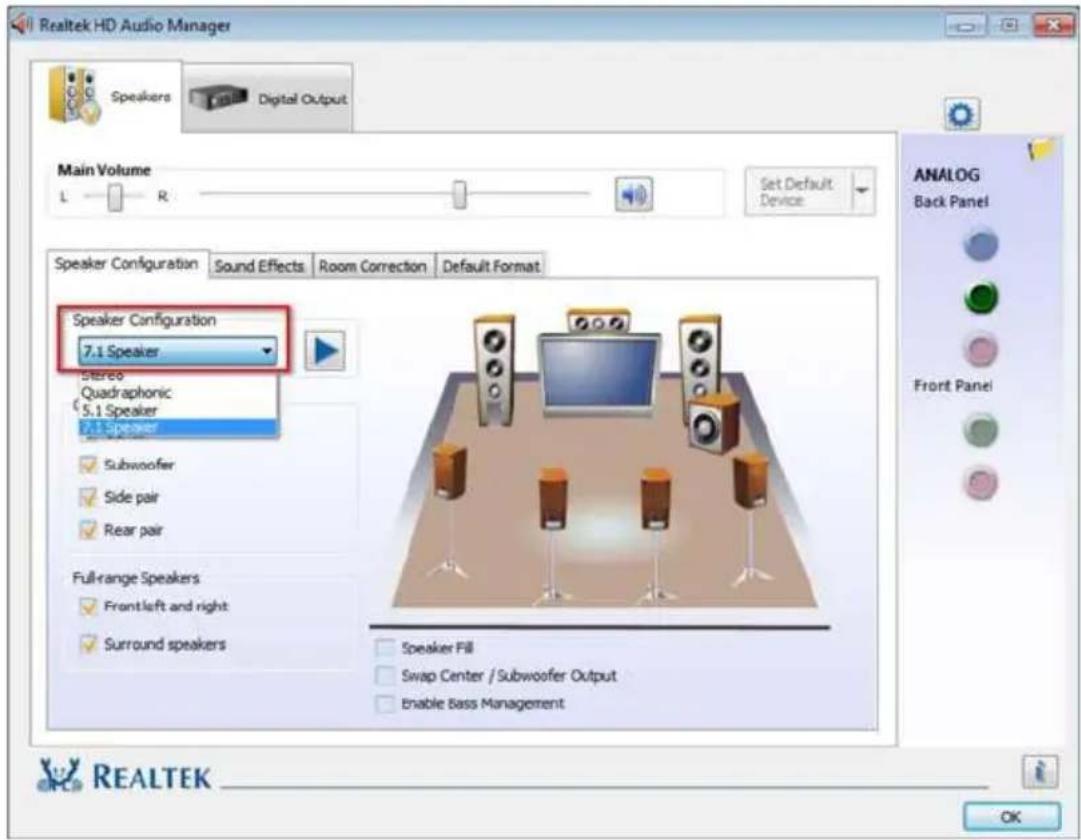
Function of the Audio Ports in 7.1-channel Configuration:
Port Function
| Light Blue (Rear panel) Rear Speaker Out | |
| Lime (Rear panel) Front Speaker Out | |
| Pink (Rear panel) Central /Subwoofer Speaker Out | |
| Lime (Front panel) Side Speaker Out |
Chapter 1 Introduction
Thank you for purchasing ASRock Z270M Pro4 motherboard, a reliable motherboard produced under ASRock's consistently stringent quality control. It delivers excellent performance with robust design conforming to ASRock's commitment to quality and endurance.

Because the motherboard specifications and the BIOS software might be updated, the content of this documentation will be subject to change without notice. In case any modifications of this documentation occur, the updated version will be available on ASRock's website without further notice. If you require technical support related to this motherboard, please visit our website for specific information about the model you are using. You may find the latest VGA cards and CPU support list on ASRock's website as well. ASRock website http://www.asrock.com.
1.1 Package Contents
ASRock Z270M Pro4 Motherboard (Micro ATX Form Factor)
- ASRock Z270M Pro4 Quick Installation Guide
- ASRock Z270M Pro4 Support CD
- 2 x Serial ATA (SATA) Data Cables (Optional)
- 2 × Screws for M.2 Sockets (Optional)
- 1 x I/O Panel Shield
1.2 Specifications
Platform
- Micro ATX Form Factor
Solid Capacitor design
CPU
Supports 7^th and 6^th Generation Intel™ Core™ i7/i5/i3/Pentium™/Celeron™ Processors (Socket 1151)
Digi Power design
6 Power Phase design
Supports Intel Turbo Boost 2.0 Technology
Supports Intel® K-Series unlocked CPUs
Supports ASRock BCLK Full-range Overclocking
Chipset
Intel® Z270
Memory
Dual Channel DDR4 Memory Technology
4x DDR4 DIMM Slots
Supports DDR4 3600 + (OC)^* / 3200(OC) / 2933(OC) / 2800 (OC)/2400**/2133 non-ECC, un-buffered memory
-
3600+(OC) memory frequency can only be achieved when a single memory module is installed (Single channel memory).
-
Please refer to Memory Support List on ASRock's website for more information. (http://www.asrock.com/)
^**7^th Gen Intel® CPU supports DDR4 up to 2400; 6^th Gen Intel® CPU supports DDR4 up to 2133.
Supports ECC UDIMM memory modules (operate in nonECC mode)
Max. capacity of system memory: 64GB
Supports Intel Extreme Memory Profile (XMP) 2.0
15μ Gold Contact in DIMM Slots
Expansion Slot
-
2 x PCI Express 3.0 x16 Slots (PCIE1: x16 mode; PCIE4: x4 mode)*
-
Supports NVMe SSD as boot disks
- 2 x PCI Express 3.0 x1 Slots (Flexible PCIe)
Supports AMD Quad CrossFireX™ and CrossFireX™
Graphics
- Intel® HD Graphics Built-in Visuals and the VGA outputs can be supported only with processors which are GPU integrated.
Supports Intel® HD Graphics Built-in Visuals : Intel® Quick Sync Video with AVC, MVC (S3D) and MPEG-2 Full HW Encode1, Intel® InTru™ 3D, Intel® Clear Video HD Technology, Intel® Insider™, Intel® HD Graphics
Gen9 LP, DX11.3, DX12 - HWAEncode/Decode: VP8, HEVC 8b, VP9, HEVC 10b (For 7^th Gen Intel® CPU)
-
HWA Encode/Decode: VP8, HEVC 8b; GPU/SWEncode/Decode: VP9, HEVC 10b (For 6^th Gen Intel® CPU)
Max. shared memory 1024MB -
The size of maximum shared memory may vary from different operating systems.
Three graphics output options: D-Sub, DVI-D and HDMI
Supports Triple Monitor
Supports HDMI with max. resolution up to 4K x 2K (4096x2160) @ 24Hz / (3840x2160) @ 30Hz
Supports DVI-D with max. resolution up to 1920x1200 @ 60Hz
Supports D-Sub with max. resolution up to 1920x1200 @ 60Hz
Supports Auto Lip Sync, Deep Color (12bpc), xvYCC and HBR (High Bit Rate Audio) with HDMI Port (Compliant HDMI monitor is required)
Supports HDCP with DVI-D and HDMI Ports
Supports Full HD 1080p Blu-ray (BD) playback with DVI-D and HDMI Ports
Audio
-
7.1 CH HD Audio with Content Protection (Realtek ALC892 Audio Codec)
-
To configure 7.1 CH HD Audio, it is required to use an HD front panel audio module and enable the multi-channel audio feature through the audio driver.
-
Premium Blu-ray Audio support
Supports Surge Protection (ASRock Full Spike Protection)
ELNA Audio Caps
LAN
- Gigabit LAN 10/100/1000 Mb/s
Giga PHY Intel® I219V
Supports Wake-On-LAN
Supports Lightning/ESD Protection (ASRock Full Spike Protection)
Supports Energy Efficient Ethernet 802.3az
Supports PXE
Rear Panel I/O
- 1 x PS/2 Mouse Port
- 1 x PS/2 Keyboard Port
- 1 x D-Sub Port
- 1xDVI-DPort
- 1xHDMI Port
- 1 x USB 2.0 Port (Supports ESD Protection (ASRock Full Spike Protection))
- 4 x USB 3.0 Type-A Ports (Supports ESD Protection (ASRock Full Spike Protection))
- 1 x USB 3.0 Type-C Port (Supports ESD Protection (ASRock Full Spike Protection))
- 1 x RJ-45 LAN Port with LED (ACT/LINK LED and SPEED LED)
- HD Audio Jacks: Line in / Front Speaker / Microphone
Storage
-
6 x SATA3 6.0 Gb/s Connectors, support RAID (RAID 0, RAID 1, RAID 5, RAID 10, Intel Rapid Storage Technology 15 and Intel Smart Response Technology), NCQ, AHCI and Hot Plug*
-
If M2_1 is occupied by a SATA-type M.2 device, SATA3_0 will be disabled.
- 1 x Ultra M.2 Socket (M2_1), supports type 2230/2242/2260/2280 M.2 SATA3 6.0 Gb/s module and M.2 PCI Express module up to Gen3 x4 (32 Gb/s)**
- 1 x Ultra M.2 Socket (M2_2), supports type 2230/2242/2260/2280 M.2 PCI Express module up to Gen3 x4 (32 Gb/s)
**Supports Intel Optane Technology
Supports NVMe SSD as boot disks
** Supports ASRock U.2 Kit
Connector
- 1 x Print Port Header
- 1xCOMPortHeader
- 1xTPMHeader
1x Chassis Intrusion and Speaker Header -
2 x CPU Fan Connectors (1 x 4-pin, 1 x 3-pin)
-
The CPU Fan Connector supports the CPU fan of maximum 1A (12W) fan power.
-
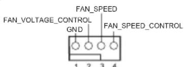
2 x Chassis Fan Connectors (4-pin) (Smart Fan Speed Control)
-
CHA_FAN1 and CHA_FAN2 can auto detect if 3-pin or 4-pin fan is in use.
-
1 x 24 pin ATX Power Connector
- 1 x 8 pin 12V Power Connector
- 1 x Front Panel Audio Connector
- 2 x USB 2.0 Headers (Support 4 USB 2.0 ports) (Supports ESD Protection (ASRock Full Spike Protection))
- 2 x USB 3.0 Headers (Support 4 USB 3.0 ports) (Supports ESD Protection (ASRock Full Spike Protection))
BIOS
Feature
AMI UEFI Legal BIOS with multilingual GUI support
ACPI 6.0 Compliant wake up events
SMBIOS 2.7 Support
CPU, GT_CPU, DRAM, PCH 1.0V, VCCIO, VCCSA, VCCST Voltage Multi-adjustment
Hardware
Monitor
- CPU/Chassis temperature sensing
CPU/Chassis Fan Tachometer - CPU/Chassis Quiet Fan (Auto adjust chassis fan speed by CPU temperature)
CPU/Chassis Fan multi-speed control
CASE OPEN detection
Voltage monitoring: +12V, +5V, +3.3V , CPU Vcore, DRAM, PCH 1.0V
os
- Microsoft® Windows® 10 64-bit (For 7^th Gen Intel® CPU)
-
Microsoft® Windows® 10 64-bit / 8.1 64-bit / 7 32-bit / 7 64-bit (For 6^th Gen Intel® CPU)
-
To install Windows® 7 OS, a modified installation disk with xHCI drivers packed into the ISO file is required. Please refer to page 142 for more detailed instructions.
-
For the updated Windows® 10 driver, please visit ASRock's website for details: http://www.asrock.com
Certifications
FCC,CE, WHQL, RCM,BSMI
ErP/EuP Ready (ErP/EuP ready power supply is required)
- For detailed product information, please visit our website: http://www.asrock.com

Please realize that there is a certain risk involved with overclocking, including adjusting the setting in the BIOS, applying Untied Overclocking Technology, or using third-party overclocking tools. Overclocking may affect your system's stability, or even cause damage to the components and devices of your system. It should be done at your own risk and expense. We are not responsible for possible damage caused by overclocking.
Chapter 2 Installation
This is a Micro ATX form factor motherboard. Before you install the motherboard, study the configuration of your chassis to ensure that the motherboard fits into it.
Pre-installation Precautions
Take note of the following precautions before you install motherboard components or change any motherboard settings.
- Make sure to unplug the power cord before installing or removing the motherboard components. Failure to do so may cause physical injuries and damages to motherboard components.
- In order to avoid damage from static electricity to the motherboard's components, NEVER place your motherboard directly on a carpet. Also remember to use a grounded wrist strap or touch a safety grounded object before you handle the components.
- Hold components by the edges and do not touch the ICs.
- Whenever you uninstall any components, place them on a grounded anti-static pad or in the bag that comes with the components.
- When placing screws to secure the motherboard to the chassis, please do not overtighten the screws! Doing so may damage the motherboard.
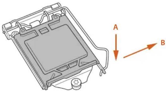
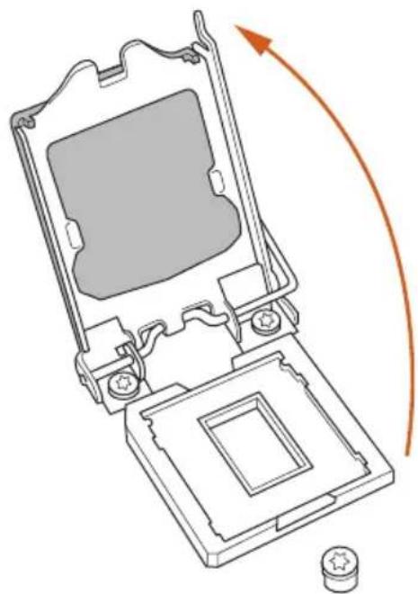
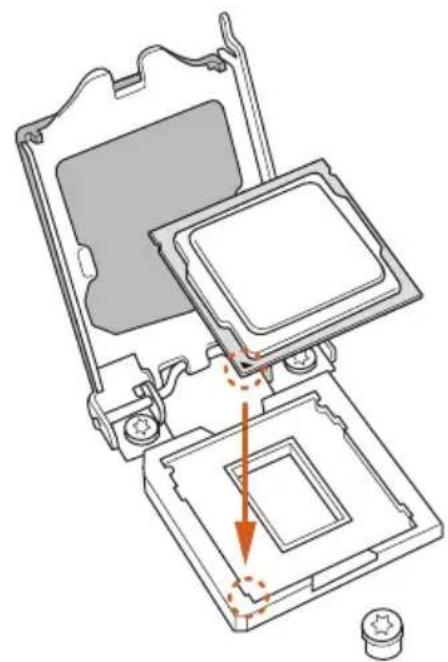
2.1 Installing the CPU

- Before you insert the 1151-Pin CPU into the socket, please check if the PnP cap is on the socket, if the CPU surface is unclean, or if there are any bent pins in the socket. Do not force to insert the CPU into the socket if above situation is found. Otherwise, the CPU will be seriously damaged.
- Unplug all power cables before installing the CPU.
1
2
3
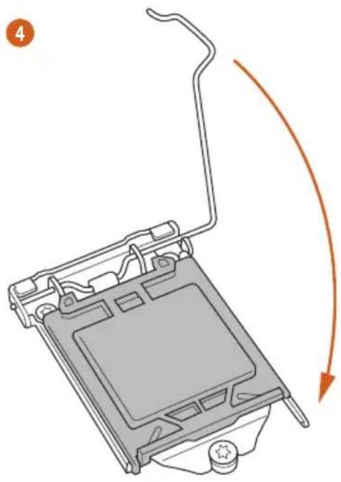
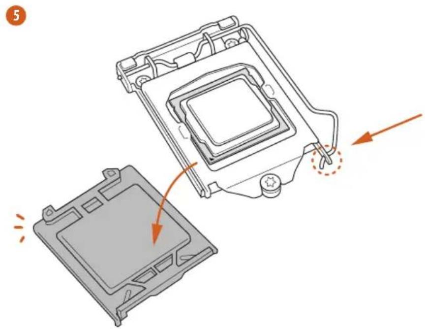

Please save and replace the cover if the processor is removed. The cover must be placed if you wish to return the motherboard for after service.
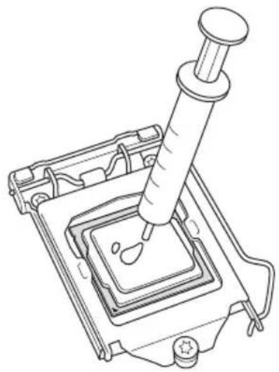
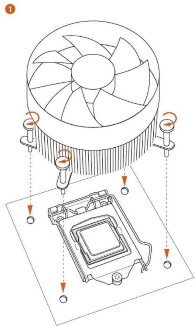
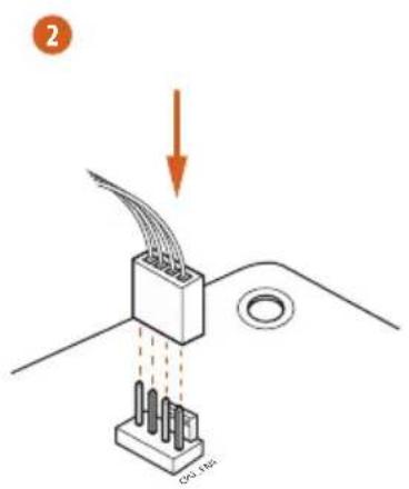
2.2 Installing the CPU Fan and Heatsink
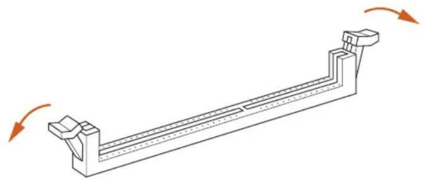
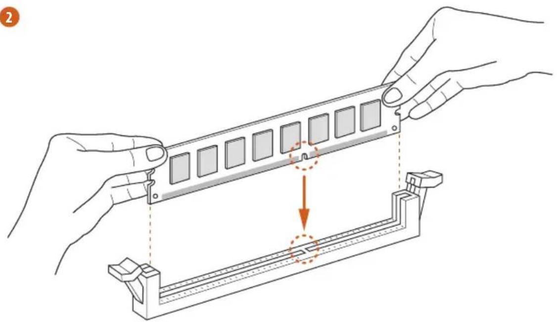
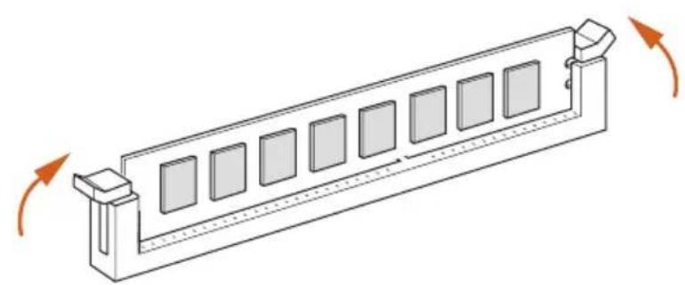
2.3 Installing Memory Modules (DIMM)
This motherboard provides four 288-pin DDR4 (Double Data Rate 4) DIMM slots, and supports Dual Channel Memory Technology.

- For dual channel configuration, you always need to install identical (the same brand, speed, size and chip-type) DDR4 DIMM pairs.
- It is unable to activate Dual Channel Memory Technology with only one or three memory module installed.
- It is not allowed to install a DDR, DDR2 or DDR3 memory module into a DDR4 slot; otherwise, this motherboard and DIMM may be damaged.
Dual Channel Memory Configuration
Priority DDR4_A1 DDR4_A2 DDR4_B1 DDR4_B2
| 1 Populated | Populated | |||
| 2 Populated | Populated | |||
| 3 Populated | Populated | Populated | Populated |

The DIMM only fits in one correct orientation. It will cause permanent damage to the motherboard and the DIMM if you force the DIMM into the slot at incorrect orientation.
1
2
3
2.4 Expansion Slots (PCI Express Slots)
There are 4 PCI Express slots on the motherboard.

Before installing an expansion card, please make sure that the power supply is switched off or the power cord is unplugged. Please read the documentation of the expansion card and make necessary hardware settings for the card before you start the installation.
PCIe slots:
PCIE1 (PCIe 3.0 x16 slot) is used for PCI Express x16 lane width graphics cards.
PCIE2 (PCIe 3.0 x1 slot) is used for PCI Express x1 lane width cards.
PCIE3 (PCIe 3.0 x1 slot) is used for PCI Express x1 lane width cards.
PCIE4 (PCIe 3.0 x16 slot) is used for PCI Express x4 lane width graphics cards.
PCIe Slot Configurations
PCIE1 PCIE4
Single Graphics Card x16 N/A
Two Graphics Cards in
CrossFireXTM Mode
x16 x4

For a better thermal environment, please connect a chassis fan to the motherboard's chassis fan connector (CHA_FAN1 or CHA_FAN2) when using multiple graphics cards.
2.5 Onboard Headers and Connectors

Onboard headers and connectors are NOT jumpers. Do NOT place jumper caps over these headers and connectors. Placing jumper caps over the headers and connectors will cause permanent damage to the motherboard.
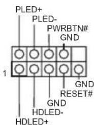
System Panel Header (9-pin PANEL1) (see p.1, No. 19)
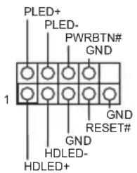
Connect the power switch, reset switch and system status indicator on the chassis to this header according to the pin assignments below. Note the positive and negative pins before connecting the cables.

PWRBTN (Power Switch):
Connect to the power switch on the chassis front panel. You may configure the way to turn off your system using the power switch.
RESET (Reset Switch):
Connect to the reset switch on the chassis front panel. Press the reset switch to restart the computer if the computer freezes and fails to perform a normal restart.
PLED (System Power LED):
Connect to the power status indicator on the chassis front panel. The LED is on when the system is operating. The LED keeps blinking when the system is in S1/S3 sleep state. The LED is off when the system is in S4 sleep state or powered off (S5).
HDLED (Hard Drive Activity LED):
Connect to the hard drive activity LED on the chassis front panel. The LED is on when the hard drive is reading or writing data.
The front panel design may differ by chassis. A front panel module mainly consists of power switch, reset switch, power LED, hard drive activity LED, speaker and etc. When connecting your chassis front panel module to this header, make sure the wire assignments and the pin assignments are matched correctly.
Chassis Intrusion and Speaker Header (7-pin SPK_CI1) (see p.1, No. 18)
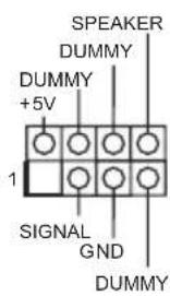
Please connect the chassis intrusion and the chassis speaker to this header.
Serial ATA3 Connectors
(SATA3_0:
see p.1, No. 9)
(SATA3_1:
see p.1, No. 10)
(SATA3_2:
see p.1, No. 13)
(SATA3_3:
see p.1, No. 14)
(SATA3_4:
see p.1, No. 16)
(SATA3_5:
see p.1, No. 15)
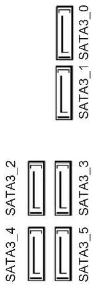
These six SATA3 connectors support SATA data cables for internal storage devices with up to 6.0 Gb/s data transfer rate. If M2_1 is occupied by a SATA-type M.2 device, SATA3_0 will be disabled.
USB 2.0 Headers
(9-pin USB3_4)
(see p.1, No. 21)
(9-pin USB5_6)
(see p.1, No. 20)
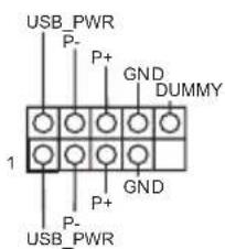
There are two headers on this motherboard. Each USB 2.0 header can support two ports.
USB 3.0 Headers (19-pin USB3_5_6) (see p.1, No.8)
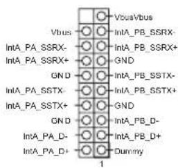
There are two headers on this motherboard. Each USB 3.0 header can support two ports.
(19-pin USB3_7_8) (see p.1, No. 12)
Front Panel Audio Header (9-pin HD=AUDIO1) (see p.1, No. 25)
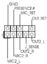
This header is for connecting audio devices to the front audio panel.

- High Definition Audio supports Jack Sensing, but the panel wire on the chassis must support HDA to function correctly. Please follow the instructions in our manual and chassis manual to install your system.
- If you use an AC'97 audio panel, please install it to the front panel audio header by the steps below:
A. Connect Mic_IN (MIC) to MIC2_L.
B. Connect Audio_R (RIN) to OUT2_R and Audio_L (LIN) to OUT2_L.
C. Connect Ground (GND) to Ground (GND).
D. MIC_RET and OUT_RET are for the HD audio panel only. You don't need to connect them for the AC'97 audio panel.
E. To activate the front mic, go to the "FrontMic" Tab in the Realtek Control panel and adjust "Recording Volume".
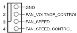
Chassis Fan Connectors (4-pin CHA_FAN1) (see p.1, No.2)
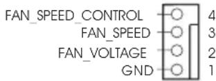
Please connect fan cables to the fan connector and match the black wire to the ground pin.
(4-pin CHA_FAN2) (see p.1, No. 11)
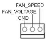
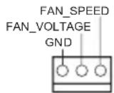
CPU Fan Connectors (4-pin CPU_FAN1) (see p.1, No.3)
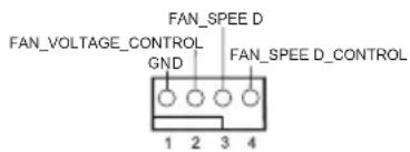
This motherboard provides a 4-Pin CPU fan (Quiet Fan) connector. If you plan to connect a 3-Pin CPU fan, please connect it to Pin 1-3.
(3-pin CPU_FAN2) (see p.1, No. 4)
ATX Power Connector (24-pin ATXPWR1) (see p.1, No.7)
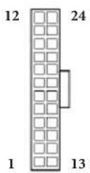
This motherboard provides a 24-pin ATX power connector. To use a 20-pin ATX power supply, please plug it along Pin 1 and Pin 13.
ATX 12V Power Connector (8-pin ATX12V1) (see p.1, No.1)
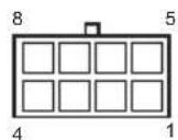
This motherboard provides an 8-pin ATX 12V power connector. To use a 4-pin ATX power supply, please plug it along Pin 1 and Pin 5.
Serial Port Header (9-pin COM1) (see p.1, No. 24)
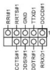
This COM1 header supports a serial port module.
TPM Header (17-pin TPMS1) (see p.1, No. 22)
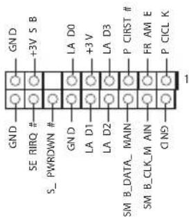
This connector supports Trusted Platform Module (TPM) system, which can securely store keys, digital certificates, passwords, and data. A TPM system also helps enhance network security, protects digital identities, and ensures platform integrity.
Print Port Header (25-pin LPT1) (see p.1, No. 23)
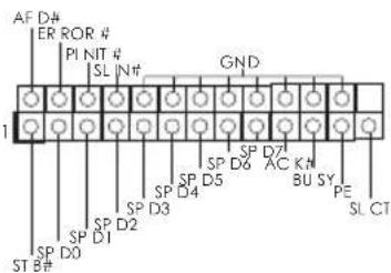
This is an interface for print port cable that allows convenient connection of printer devices.
2.6 M.2_SSD (NGFF) Module Installation Guide
The M.2, also known as the Next Generation Form Factor (NGFF), is a small size and versatile card edge connector that aims to replace mPCIe and mSATA. The Ultra M.2 Socket (M2_1) supports type 2230/2242/2260/2280 M.2 SATA3 6.0 Gb/s module and M.2 PCI Express module up to Gen3 x4 (32 Gb/s). The Ultra M.2 Socket (M2_2) supports type 2230/2242/2260/2280 M.2 PCI Express module up to Gen3 x4 (32 Gb/s).
- Please be noted that if M2_1 is occupied by a SATA-type M.2 device, SATA3_0 will be disabled.
Installing the M.2_SSD (NGFF) Module
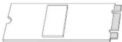
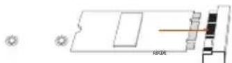
Step 1
Prepare a M.2_SSD (NGFF) module and the screw.
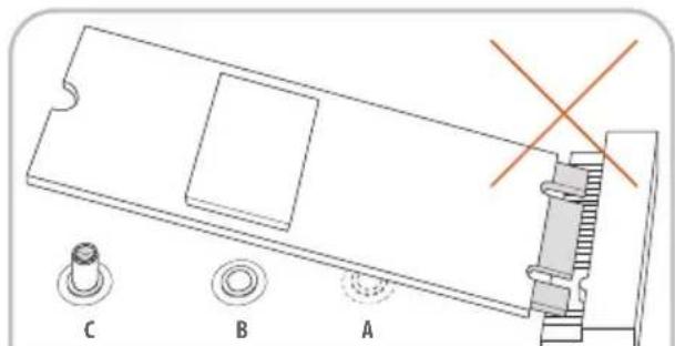
Step 2
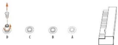
Depending on the PCB type and length of your M.2_SSD (NGFF) module, find the corresponding nut location to be used.
No.1234
Nut Location A B C D
Move the standoff based on the module type and length.
The standoff is placed at the nut location D by default. Skip Step 3 and 4 and go straight to Step 5 if you are going to use the default nut.
Otherwise, release the standoff by hand.


Step 4
Peel off the yellow protective film on the nut to be used. Hand tighten the standoff into the desired nut location on the motherboard.
Step 5
Align and gently insert the M.2 (NGFF) SSD module into the M.2 slot. Please be aware that the M.2 (NGFF) SSD module only fits in one orientation.
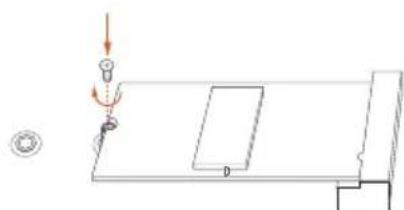
Step 6
Tighten the screw with a screwdriver to secure the module into place. Please do not overtighten the screw as this might damage the module.
M.2_SSD (NGFF) Module Support List
| Vendor Size Interface Length P/N | ||
| ADATA 128GB SATA3 2280 AXNS381E-128GM-B | ||
| ADATA 256GB SATA3 2280 AXNS381E-256GM-B | ||
| ADATA 32GB SATA3 2230 AXNS330E-32GM-B | ||
| Crucial 120GB SATA3 2280 CT120M500SSD4 | ||
| Crucial 240GB SATA3 2280 CT240M500SSD4 | ||
| Intel 80GB SATA3 2280 Intel SSDSCGKW080A401/80G | ||
| Intel 256GB PCIe3 x4 2280 SSDPEKKF256G7 | ||
| Intel 512GB PCIe3 x4 2280 SSDPEKKF512G7 | ||
| Kingston | 120GB SATA3 2280 SM2280S3 | |
| Kingston | 480GB PCIe2 x4 2280 SH2280S3/480G | |
| OCZ | 512GB PCIe3 x4 2280 RVD400 -M2280-512G (NVME) | |
| Plextor | 128GB PCIe3 x4 2280 PX-128M8PeG | |
| Plextor | 1TB PCIe3 x4 2280 PX-1TM8PeG | |
| Plextor | 256GB PCIe3 x4 2280 PX-256M8PeG | |
| Plextor | 256GB PCIe 2280 PX-G256M6e | |
| Plextor | 512GB PCIe3 x4 2280 PX-512M8PeG | |
| Plextor | 512GB PCIe 2280 PX-G512M6e | |
| Samsung | 256GB PCIe3 x4 2280 SM951 (MZHPV256HDGL) | |
| Samsung | 256GB PCIe3 x4 2280 SM951 (NVME) | |
| Samsung | 512GB PCIe3 x4 2280 SM951 (MZHPV512HDGL) | |
| Samsung | 512GB PCIe3 x4 2280 SM951 (NVME) | |
| Samsung | 512GB PCIe x4 2280 XP941-512G (MZHPU512HCGL) | |
| SanDisk | 128GB PCIe 2260 SD6PP4M-128G | |
| SanDisk | 256GB PCIe 2260 SD6PP4M-256G | |
| Team | 128GB SATA3 2242 TM4PS4128GMC105 | |
| Team | 128GB SATA3 2280 TM8PS4128GMC105 | |
| Team | 256GB SATA3 2280 TM8PS4256GMC105 | |
| Team | 256GB SATA3 2242 TM4PS4256GMC105 | |
| Transcend | 256GB SATA3 2242 TS256GMTS400 | |
| Transcend | 512GB SATA3 2260 TS512GMTS600 | |
| Transcend | 512GB SATA3 2280 TS512GMTS800 | |
| V-Color 120GB SATA3 2280 VLM100-120G-2280B-RD | ||
| V-Color 240GB SATA3 2280 VLM100-240G-2280B-RD | ||
| V-Color 240GB SATA3 2280 VSM100-240G-2280 | ||
For the latest updates of M.2_SSD (NFGG) module support list, please visit our website for details: http://www.asrock.com
1 Einleitung
1.3 Kolodkn npa3beMbI, pacnoJooKeHHbIe Ha MaTePNHcKoI pNaTe

Pacnoonkne hne ha mamepuhckou nane konoeku u pa3bemy nepembukamu HE yomcm. HE ycmahaabuaime ha 3mu konodku u pa3bemy konnaucobie nepembuku. Ycmanoaka konnaucobx nepbueke na 3mu konodku u pa3bemy mokeb bmbheympanoe nobpekdene mamepunckou narnbl.
KoIIOKa cnCTeMHoH
HaeJIN
(9-KoHTaKTHa, PANEL1)
(CM. cTp. 1, N° 19)
IoiKIOUOHTe
pacIOIOKeHHbIe Ha KOpIyCe BbIKIOuHaTeII IITaHn, KHOIIKy Ipe3arpy3Kn HINIKaTOP COCTOHN CNTeMbK 3TOI KOIOJ
B COOTBeTCTBn C
paCIIpeIeJIeHHeM
KoHTaKTOB,
IIpNBeIeHHbIM HIXKe.
IlepeI IOIKIIOyeHHeM
Ka6eIe ONPeIeJIte
IOJOKHTeJIbHbI
HOtpNtAteJIbHbI
KoHTaKTbI.

PWRBTN (Khonka numahan):
Iodkouene Khonku numaun, pacnojokennou ha nepehne nahenu kopyca. MoKho nacmpounb nopdoK bblknouenue cucmemb c ucnonb3oabaum Khonku numaun.
RESET (knonka nepe3a2py3ku):
IIOKluoyehue KhoNku nepe3a2py3ku cucmembl, pacnoonkeHHoHa nepeedne naenu Kopnyca. HaKmume KhoNky nepe3a2py3ku, uMo6b nepe3anycmmb kOmnbomep, eCuu on 3abuc u hopmaNbHt 3anyck Hebo3moJcH.
PLED (cemboduoohbui unoukamop numanu cucmembl):
Iodkouenue uDukamopa ccmohn, pacnookhenzo ha nepehdne nanenu Kopnyca. Cbemoduobhui undukamop zopum, kozda cucmema paobomaem. Kozda cucmema haxodumc 6 pekume okudanu S1/S3, cbemoduod muaem. Koeda cucmema haxodumc 8 pekume okudanu S4 wuu bkyouena (S5), cbemoduod he zopum.
HDLED (cemboduoohbu undukamop paobomn kecmko o ducka):
IIOKIOHue CbeMoOoHOo unOukamopapabomkkecmkoDucka, pacnoJKeHHoHa nepeohne naehu. CbeMoOoHb uHouKamop oOpum, Ko0da kecmku duck bblonnem cunmbabaue uu 3anuc dahbx.
Ipeodnnaenb moem 6bmb pa3no ha pa3nbx Kopnycax. B ochobnom nepeohnaenb bknoaem b cebk honky numanu, knonky nepe3aepy3ku, cbemoduohn unukamop numanu, cbemoduohn uhdukamop pabomj kecmko zo dcca, duhamuk u m.d. Ipu nooknoehnu nepedne naheu Kmou KOJODKe npabulho nokkouaume npoboda K konmakmam.
IpoBoJaK3a3eMJIeHnIO.
Pa3bEmbI BeHTnJIrTOPOB II
(4-KoHTaKTHbI, CPU_FAN1)
(CM.cTp.1,N3)
(3-KoHTaKTbI, CPU_FAN2)
(CM. cTp. 1, N² 4)
TaMaTepeHCKa
IIaTa cHa6KeHa
4-KOHTaKTHbIM pa3beMOM
IIIA MaIOIyMMAIETO
BeHTnIaTopa III. EcIN Bbl co6npaTecb IOKJIIOUHTb
3-KOHTaKTbH
BeHTNIJTOP OXlaKJdeHnI IpoIeCCopa,IOJIKNIOuAHTero K KOHTaKTam 1-3.
PWRBTN (Güç Anahtar):
| ATX 전원 친quette (24 Pan ATXPWR1) (1 Pin, 7 Byte整形槓座) | 12 24 1 13 | i 易大幅変態のは 24 Pin ATX 전원 친quette가 희 재出于成就感不如 .20 Pin ATX 전원공GCC장지를 사 용어려면 Pan 1과 Pan 13을 라에 갔에 heart상存在一定. 如此 如此 |
| ATX 12V 전원 친quette (8 Pin ATX12V1) (1 Pin, 1 Byte整形槓座) | 8 5 4 1 | i 易大幅変態/of 8 Pin ATX 12V 전원 친quette가 Tah재出于成就感不如 .4 Pin ATX 전원공GCC장지를 사 용어려면 Pan 1과 Pan 5을 如此 如此 |
| SiRlEe foTr th HeDe (9 Pin COM1) (1 Pin, 24 Byte整形槓座) | RRU#1 RRRTS#1 GND DDSR#1 TDX1 DDCD#1 CCTS#1 DDS#1 DTR#1 RRX#1 | i COM1 썼다는 siRlEe foTr th Mo들울지원道路上. 如此 |
| TPM HeDa (17 Pin TPMS1) (1 Pin, 22 Byte整形槓座) | GND SE BRQ #3VS B LDA D0 GND LDA D1 LDA D2 P CIR ST #FR AM E SM B DATA M ANINON SM B CLK MA IN ON | i 凡 i i i i i i i i i i i i i i i i i i i i i i i i i i i i i i i i i i i i i i i i i i i i i i i i i i 1 1 1 1 1 1 1 1 1 1 1 1 1 1 1 1 1 1 1 1 1 1 1 1 1 1 1 1 1 1 1 1 1 1 1 1 1 1 1 1 1 1 1 1 1 1 1 1 1 1 2 2 2 2 2 2 2 2 2 2 2 2 2 2 2 2 2 2 2 2 2 2 2 2 2 2 2 2 2 2 2 2 2 2 2 2 2 2 2 2 2 2 2 2 2 2 2 2 2 2 1 1 1 1 1 1 1 1 1 1 1 1 1 1 1 1 1 1 1 1 1 1 1 1 1 1 1 1 1 1 1 1 1 1 1 1 1 1 1 1 1 1 1 1 1 1 1 1 1 i i i i i i i i i i i i i i i i i i i i i i i i i i i i i i i i i i i i i i i i i i i i i i i i i I I I I I I I I I I I I I I I I I I I I I I I I I I I I I I I I I I I I I I I I I I I I I I I I I I 1 1 1 1 1 1 1 1 1 1 1 1 1 1 1 1 1 1 1 1 1 1 1 1 1 1 1 1 1 1 1 1 1 1 1 1 1 1 1 1 1 1 1 1 1 1 1 1 1 I I I I I I I I I I I I I I I I I I I I I I I I I I I I I I I I I I I I I I I I I I I I I I I I I i i i i i i i i i i i i i i i i i i i i i i i i i i i i i i i i i i i i i i i i i i i i i i i i i l l l l l l l l l l l l l l l l l l l l l l l l l l l l l l l l l l l l l l l l l l l l l l l l l l I I I I I I I I I I I I I I I I I I I I I I I I I I I I I I I I I I I I I I I I I I I I I I I I I l l l l l l l l l l l l l l l l l l l l l l l l l l l l l l l l l l l l l l l l l l l l l l l l l 1 1 1 1 1 1 1 1 1 1 1 1 1 1 1 1 1 1 1 1 1 1 1 1 1 1 1 1 1 1 1 1 1 1 1 1 1 1 1 1 1 1 1 1 1 1 1 1 1 l l l l l l l l l l l l l l l l l l l l l l l l l l l l l l l l l l l l l l l l l l l l l l l l l r r r r r r r r r r r r r r r r r r r r r r r r r r r r r r r r r r r r r r r r r r r r r r r r r r l l l l l l l l l l l l l l l l l l l l l l l l l l l l l l l l l l l l l l l l l l l l l l l l l i i i i i i i i i i i i i i i i i i i i i i i i i i i i i i i i i i i i i i i i i i i i i i i i i r r r r r r r r r r r r r r r r r r r r r r r r r r r r r r r r r r r r r r r r r r r r r r r r r I I I I I I I I I I I I I I I I I I I I I I I I I I I I I I I I I I I I I I I I I I I I I I I I I II II II II II II II II II II II II II II II II II II II II II II II II II II II II II II II II II II II II II II II II II II II II II II II II II II I I I I I I I I I I I I I I I I I I I I I I I I I I I I I I I I I I I I I I I I I I I I I I I I I L L L L L L L L L L L L L L L L L L L L L L L L L L L L L L L L L L L L L L L L L L L L L L L L L L L I I I I I I I I I I I I I I I I I I I I I I I I I I I I I I I I I I I I I I I I I I I I I I I I I I I I I I I I I I I I I I I I I I I I I I I I I I I I I I I I I I I I I I I I I I I I I I I I I I I I l l l l l l l l l l l l l l l l l l l l l l l l l l l l l l l l l l l l l l l l l l l l l l l l l l |
1はじてに

1.1 ロック一的内容

1.2仕樣
PLA TTO
才一
CPU
TM i7/i5/i3/Pentium*/
Digi Power design
丁FFF
M
拋張丶口卜
TM
TM
gla f
Ks
TM
TM
(3840x2160) @ 30Hz
才一才
LAN
LARAB
I/O
St-Leje
** Intel* OptaneTM
不夕
BIOS 機能
八一丁工
芒二夕一
os
認証

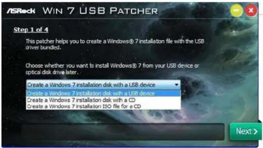
Enabling USB Ports for Windows® 7 Installation
Intel® new processors have removed their support for the Enhanced Host Controller Interface (EHCI - USB2.0) and only kept the eXtensible Host Controller Interface (XHCI - USB3.0). Due to that fact that XHCI is not included in the Windows 7 inbox drivers, users may find it difficult to install Windows 7 operating system because the USB ports on their motherboard won't work. In order for the USB ports to function properly, please create a Windows® 7 installation disk with the Intel® USB 3.0 eXtensible Host Controller (xHCI) drivers packed into the ISO file.
Requirements
- A Windows® 7 installation disk or USB drive
A Windows PC - Win7 USB Patcher (included in the ASRock Support CD or downloaded from website)
Scenarios
You have an ODD and PS/2 ports:
If there is an optical disc drive, PS/2 ports and PS/2 Keyboard or mouse on your computer, you can skip the instructions below and go ahead to install Windows® 7 OS.
You've got nothing:
If you do not have an optical disc drive, please find another computer and follow the instructions below to create a new ISO file with the "Win7 USB Patcher". Then use the new patched Windows® 7 installation USB drive to install Windows® 7 OS.
Instructions
Step 1
Insert the Windows® 7 installation disk or USB drive to your system.
Step 2
Extract the tool (Win7 USB Patcher) and launch it.
Step 3
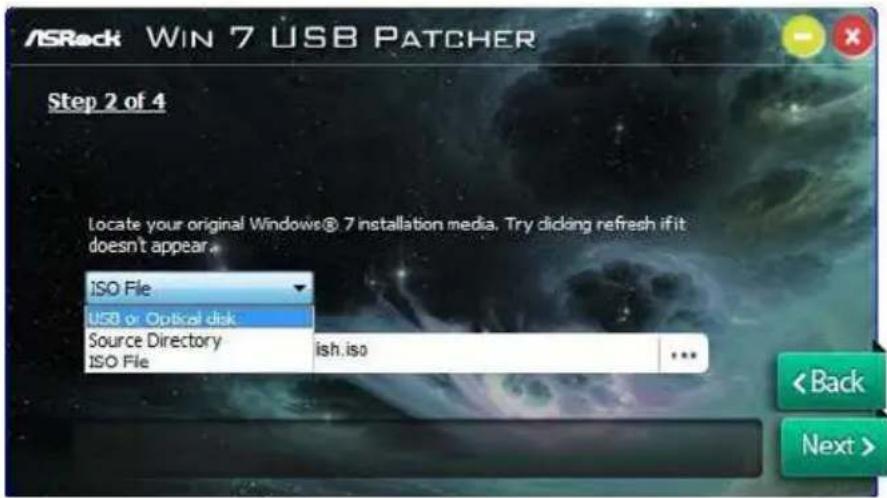
Select how you want to install Windows 7 later.
Step 4
Locate your Win7 source folder or your ISO file.
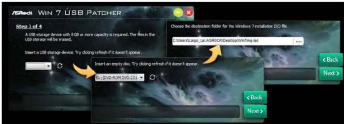
Step 5
Select the USB storage, compact disk or destination folder for the new Windows 7 installation file.
Step 6
Click "Start" to begin.
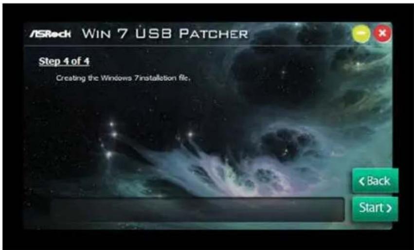
Step 7
Now you are able to install Windows 7 on Intel new processors with the new burned CD. Or please use the patched ISO image to make an OS USB drive to install the OS.
Contact Information
If you need to contact ASRock or want to know more about ASRock, you're welcome to visit ASRock's website at http://www.asrock.com; or you may contact your dealer for further information. For technical questions, please submit a support request form at http://www.asrock.com/support/tsd.asp
ASRock Incorporation
2F., No.37, Sec. 2, Jhongyang S. Rd., Beitou District,
Taipei City 112, Taiwan (R.O.C.)
ASRock EUROPE B.V.
Bijsterhuizen 11-11
6546 AR Nijmegen
The Netherlands
Phone: +31-24-345-44-33
Fax: +31-24-345-44-38
ASRock America, Inc.
13848 Magnolia Ave, Chino, CA91710
U.S.A.
Phone: +1-909-590-8308
Fax: +1-909-590-1026
For the following equipment:
Motherboard
(Product Name)
Z270M Pro4/ASRock
(Model Designation / Trade Name)
ASRock Incorporation
(Manufacturer Name)
2F., No.37, Sec. 2, Jhongyang S. Rd., Beitou District, Taipei City 112, Taiwan (R.O.C.)
(Manufacturer Address)
is herewith confirmed to comply with the requirements set out in the Council
Directive on the Approximation of the Laws of the Member States relating to
Electromagnetic Compatibility Directive (2004/108/EC) and Safety Directive (2006/95/
EC), the following standards are applied:
EN 55022:2006+A1:2007
EN 61000-3-2: 2009
EN 61000-3-3:2008
EN 55024:1998 + A1:2001 + A2:2003
IEC 61000-4-2: 2008;
IEC 61000-4-3:2010; IEC 61000-4-4:2010
IEC 61000-4-5:2005; IEC 61000-4-6:2008
IEC 61000-4-8:2009;IEC 61000-4-11:2004
EN 60950-1:2005 + A1:2009
IEC 60950-1:2006 + A11:2009 + A1:2010 + A12:2011
The following manufacturer / importer or authorized representative established within the EUT is responsible for this declaration:
ASRock EUROPE B.V.
(Company Name)
Bijsterhuizen 1111 6546 AR Nijmegen The Netherlands
(Company Address)
Person responsible for making this declaration:

(Name, Surname)
A.V.P
(Position / Title)
Nov. 11, 2016
(Date)