73001iDF - Generator Champion - Free user manual and instructions
Find the device manual for free 73001iDF Champion in PDF.
| Technical Specifications | Champion 73001iDF gasoline generator, 2800W power, 4-stroke engine, 4.5-liter tank. |
|---|---|
| Usage | Ideal for camping activities, construction sites, and as a backup power source. |
| Maintenance and Repair | Regularly check engine oil, clean the air filter, and monitor fuel level. |
| Safety | Use only outdoors to avoid carbon monoxide buildup, follow safety instructions when starting. |
| General Information | Weight: 25 kg, noise level: 58 dB, 2-year warranty. |
Frequently Asked Questions - 73001iDF Champion
User questions about 73001iDF Champion
0 question about this device. Answer the ones you know or ask your own.
Ask a new question about this device
Download the instructions for your Generator in PDF format for free! Find your manual 73001iDF - Champion and take your electronic device back in hand. On this page are published all the documents necessary for the use of your device. 73001iDF by Champion.
USER MANUAL 73001iDF Champion
U.S. Patent No. D710,802

This manual covers the following models:
73001I-DF (EU/SC)
NORSK
SUOMEN KIELI
EESTI
FRANÇAIS
POLSKI
Introduction
Congratulations on purchasing your inverter generator. Please follow these instructions and maintain it correctly.
Portable Power Generator
This unit is a petrol engine driven AC generator used for supply electrical power.
Accessories
CPE manufactures and supplies a series of accessories. See local dealer for more information.
This Booklet
We reserve the right to change, alter or improve the product and this manual without prior notice.
Record the model and serial numbers as well as date and place of purchase for future reference. Have this information available when ordering parts and when making technical or warranty inquiries.
| Champion Power Equipment Support |
| Model Number |
| Serial Number |
| Date of Purchase |
| Purchase Location |
Please familiarize yourself with the following symbols. The safety symbol and key words are safety warnings. Follow all safety messages to avoid accidents or injury.

DANGER
DANGER indicates an imminently hazardous situation which, if not avoided, will result in death or serious injury.

WARNING
WARNING indicates a potentially hazardous situation which, if not avoided, could result in death or serious injury.

CAUTION
CAUTION indicates a potentially hazardous situation which, if not avoided, may result in minor or moderate injury.
CAUTION
CAUTION used without the safety alert symbol indicates a potentially hazardous situation which, if not avoided, may result in property damage.

NOTE
If you have questions regarding your generator, we can help. Please contact your local dealer.

WARNING
Read this manual thoroughly before operating your generator. Failure to follow instructions could result in serious injury or death.

WARNING
The engine exhaust from this product contains chemicals that are known to cause serious health problems and even death.

DANGER
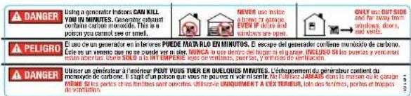
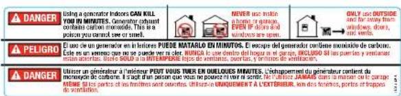
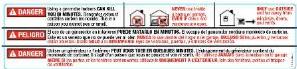
Generator exhaust contains carbon monoxide, a colourless, odourless, poison gas. Breathing carbon monoxide will cause nausea, dizziness, fainting or death. If you start to feel dizzy or weak, get to fresh air immediately.
Operate generator outdoors only in a well ventilated area.
DO NOT operate the generator inside any building, including garages, basements, crawlspaces and sheds, enclosure or compartment, including the generator compartment of a recreational vehicle. DO NOT allow exhaust fumes to enter a confined area through windows, doors, vents or other openings.
DANGER CARBON MONOXIDE: using a generator indoors CAN KILL YOU IN MINUTES.

DANGER
Generator produces powerful voltage.
DO NOT touch bare wires or receptacles.
DO NOT use electrical cords that are worn, damaged or frayed.
DO NOT operate generator in wet weather.
DO NOT allow children or unqualified persons to operate or service the generator
Use a ground fault circuit interrupter (GFCI) in damp areas and areas containing conductive material such as metal decking.
Use approved transfer equipment to isolate generator from your electric utility and notify your utility company before connecting your generator to your power system.

WARNING
Sparks can result in fire or electrical shock.
When servicing the generator:
Disconnect the spark plug wire and place it where it cannot contact the plug.
DO NOT check for spark with the plug removed.
Use only approved spark plug testers.

WARNING
Running engines produce heat. Severe burns can occur on contact.
Combustible material can catch fire on contact.
DO NOT touch hot surfaces.
Avoid contact with hot exhaust gases.
Allow equipment to cool before touching.
Maintain at least 3 ft. (91.4 cm) of clearance on all sides to ensure adequate cooling.
Maintain at least 5 ft. (1.5 m) of clearance from combustible materials.

WARNING
Medical and Life Support Uses.
In case of emergency, call emergency services.
NEVER use this product to power life support devices or life support appliances.
NEVER use this product to power medical devices or medical appliances.
Inform your electricity provider immediately if you or anyone in your household depends on electrical equipment to live.
Inform your electrical provider immediately if a loss of power would cause you or anyone in your household to experience a medical emergency.

WARNING
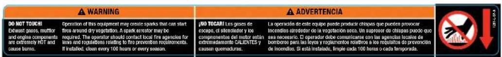
Operation of this equipment may create sparks that can start fires around dry vegetation.
A spark arrester may be required. The operator should contact local fire agencies for laws or regulations relating to fire prevention requirements.

DANGER
Rotating parts can entangle hands, feet, hair, clothing and/or accessories.
Traumatic amputation or severe laceration can result.
Keep hands and feet away from rotating parts. Tie up long hair and remove jewelry.
Operate equipment with guards in place.
DO NOT wear loose-fitting clothing, dangling drawstrings or items that could become caught.

WARNING
Rapid retraction of the starter cord will pull hand and arm towards the engine faster than you can let go. Unintentional startup can result in entanglement, traumatic amputation or laceration.
Broken bones, fractures, bruises or sprains could result.
When starting engine, pull the starter cord slowly until resistance is felt and then pull rapidly to avoid kickback.
DO NOT start or stop the engine with electrical devices plugged in.

CAUTION
Exceeding the generator's running capacity can damage the generator and/or electrical devices connected to it.
DO NOT overload the generator.
Start the generator and allow the engine to stabilize before connecting electrical loads.
Connect electrical equipment in the off position, and then turn them on for operation.
Turn electrical equipment off before stopping the generator.
DO NOT tamper with the governed speed.
DO NOT modify the generator in any way.

CAUTION
Improper treatment or use of the generator can damage it, shorten its life and void your warranty.
Use the generator only for intended uses.
Operate only on level surfaces.
DO NOT expose generator to excessive moisture, dust, or dirt.
DO NOT allow any material to block the cooling slots.
If connected devices overheat, turn them off and disconnect them from the generator.
DO NOT use the generator if:
– Electrical output is lost
– Equipment sparks, smokes or emits flames
– Equipment vibrates excessively
Fuel Safety

DANGER
PETROL, PETROL VAPORS AND LIQUID PETROLEUM GAS (LPG) ARE HIGHLY FLAMMABLE AND EXPLOSIVE.
Fire or explosion can cause severe burns or death. Unintentional startup can result in entanglement, traumatic amputation or laceration.
Petrol and Petrol Vapors (Petrol):
- PETROL IS HIGHLY FLAMMABLE AND EXPLOSIVE.
- Petrol can cause a fire or explosion if ignited.
- Petrol is a liquid fuel but it's vapors can ignite.
- Petrol is a skin irritant and needs to be cleaned up immediately if spilled on skin or clothes.
- Petrol has a distinctive odor, this will help detect potential leaks quickly.
- In any petrol fire, flames should not be extinguished unless by doing so the fuel supply valve can be turned OFF. This is because if a fire is extinguished and a supply of fuel is not turned OFF, then an explosion hazard could be created.
- Petrol expands or contracts with ambient temperatures. Never fill the petrol tank to full capacity, as petrol needs room to expand if temperatures rise.
Liquefied Petroleum Gas (Propane/LPG):
- LPG (PROPANE) IS HIGHLY FLAMMABLE AND EXPLOSIVE.
- Flammable gas under pressure can cause a fire or explosion if ignited.
- LPG (propane) is heavier than air and can settle in low places while dissipating.
- LPG (propane) has a distinctive odor added to help detect potential leaks quickly.
- In any petroleum gas fire, flames should not be extinguished unless by doing so the fuel supply valve can be turned OFF. This is because if a fire is extinguished and a supply of fuel is not turned OFF, then an explosion hazard could be created.
- When exchanging LPG cylinders, be sure the cylinder valve is of the same type.
- Always keep the LPG cylinder in an upright position.
- LPG will burn skin if it comes in contact with it. Keep any and all LPG away from skin at all times.
When adding or removing Petrol:
Turn the generator off and let it cool for at least two minutes before removing the fuel cap. Loosen the cap slowly to relieve pressure in the tank.
Only fill or drain fuel outdoors in a well-ventilated area.
DO NOT pump petrol directly into the generator at the petrol station. Use an approved container to transfer the fuel to the generator.
DO NOT overfill the fuel tank.
Always keep fuel away from sparks, open flames, pilot lights, heat and other sources of ignition.
DO NOT light or smoke cigarettes.
When starting the generator:
DO NOT attempt to start a damaged generator.
Make certain that the petrol cap, air filter, spark plug, fuel lines and exhaust system are properly in place.
Allow spilled fuel to evaporate fully before attempting to start the engine.
Make certain that the generator is resting firmly on level ground.
When operating the generator:
DO NOT move or tip the generator during operation. DO NOT tip the generator or allow fuel or oil to spill.
When transporting or servicing the generator:
Make certain that the fuel shutoff valve is in the off position and the fuel tank is empty.
Make certain that a LPG cylinder is not attached to generator and is securely stowed away.
Disconnect the spark plug wire.
When storing the generator:
Store away from sparks, open flames, pilot lights, heat and other sources of ignition.
Do not store generator, petrol or LPG cylinder near furnances, water heaters, or any other appliances that produce heat or have automatic ignitions.

WARNING
Never use a petrol container, LPG connector hose, petrol tank, LPG cylinder or any other fuel item that is damaged or appears damaged.
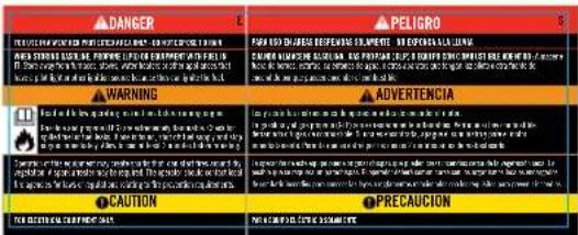
Safety Label Locations
These labels warn you of potential hazards that can cause serious injury. Read them carefully.
If a label comes off or becomes hard to read, contact your local dealer's customer service department for possible replacement.
natural_image
Technical line drawing of a mechanical component with labeled parts A, B, and C (no text or symbols beyond labels)
text_image
D E
natural_image
Technical line drawing of a portable air conditioner unit with ventilation grilles and fan (no text or symbols)A

text_image
15M MINIMUM DESPICE MINIMUM DEPROM ICE 5ET 350000 MINIMUM 1.5MB
©
text_image
DANGER Using a generator index can kill YOU IN MINUTES. Canpower obtain contains carbon monoxide. This is a poison you cannot ever or smell. NEVER use index above or garage, EV/FE above and windows are open. GKTY OUTSIDE and far soars from windings, doors, and vents. PELIGRO Use a un generator in air berances POIDE MATA RLO EN MINUTOS. E escape the generator confiene monoxide de carbono. Cate us an essence que se plude ver in mer. NONCA Use deserts del gasan en el garaje. INCLUDE SI les portes y ventantes make a better use. Use 3000 la mi ETI PERIE. Les portes en lovrages, y estre de verificación. DANGER Ulinear un generator à l'impéret PEOT YOU TOER EN QUELOQUES MINUTES. L'échoppement du generation content du moment d'une concorne. Et cagl une poisson que vous ne pouvue qu'il net sur le plus de la carment dans le mouten ou le garaje. ANME SI les portes aux famines sont correctes. Utilise une UNQUENDÉT À L'EX TIERIEUR, telon des fermions, portes et tropes de verificación.D

text_image
DANGER PENGENT WORKS ARE NOT TO BE REPROVED. WE HAVE IT IS NOT TO USE IT AS WHERE STANDING GEARLIFE, PREVENTING LIME AND THE DURING WITH YOUR LIFE, AND ANY OTHER THAN THE FUTURE, JUSTICE, WATER, WATER & Other. Please note that WARNING: A warning of the person's life is not to be able to use it. WARNING: ADVERTENCIA CAUTION: PRECAUTION FOR CUSTEEN CUSTEEN CUSTEEN FOR SCIENTIFIC CUSTEEN CUSTEENE
text_image
Sign for STOP/ALTO/ARRÊT showing a French-language product listing with instructions and certification marks.F
Your generator requires some assembly. This unit ships from our factory without oil. It must be properly serviced with fuel and oil before operation.
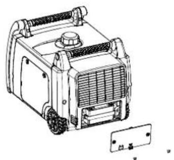
Remove the Generator from the Shipping Carton
- Set the shipping carton on a solid, flat surface.
- Remove everything from the carton except the generator.
- Using the carrying handles of the unit, carefully remove the generator from the box. (two people lifting is recommended)
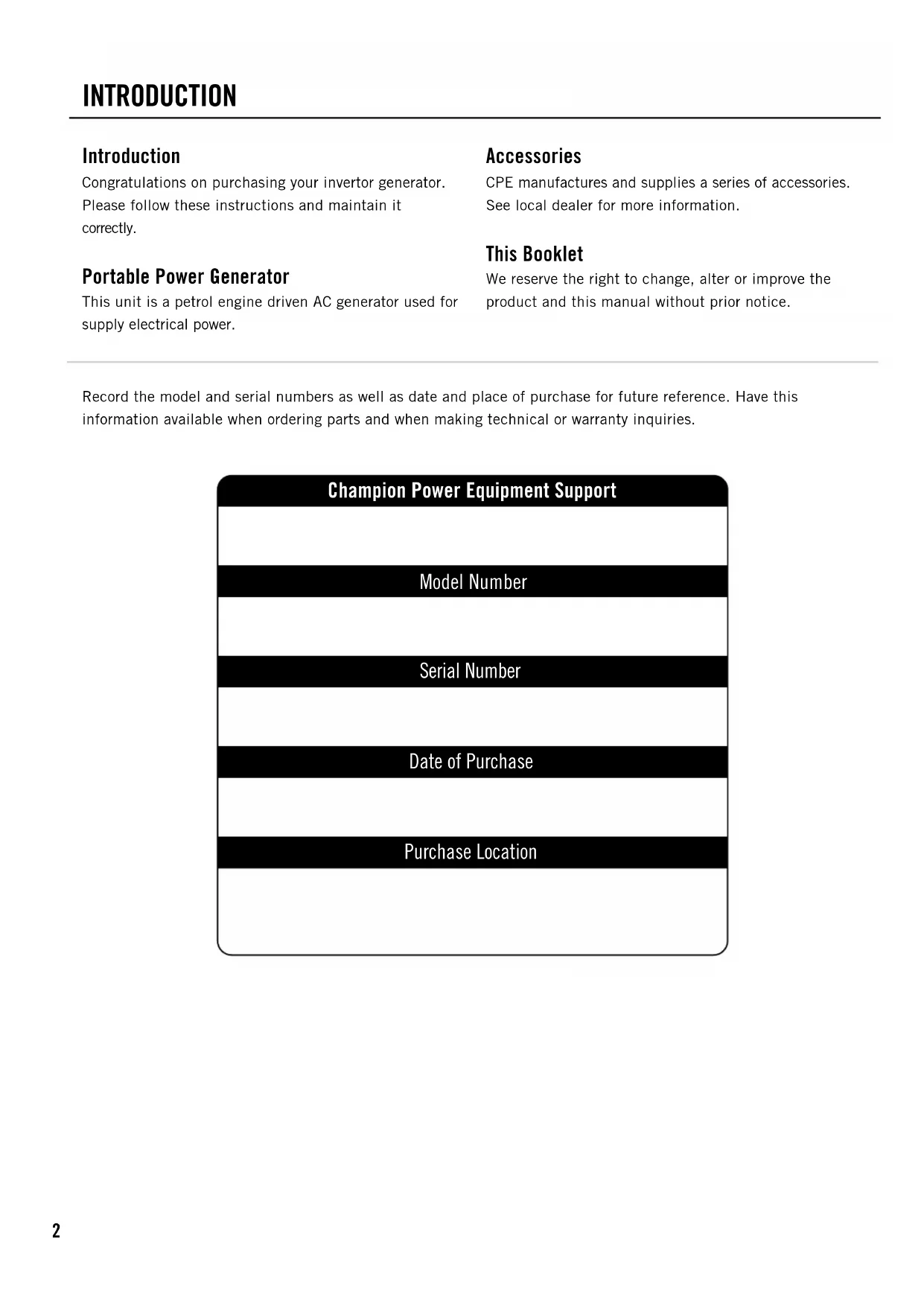
Connecting the Battery (Electric Start Models)
- Using a screwdriver, remove the two (2) maintenance cover screws from the battery maintenance cover. (A)
- Once the screws have been removed, the rubber pull-tab on the cover can be pulled out to help loosen and dislodge the maintenance cover. (A)
- Remove the battery maintenance cover. (A)
natural_image
Technical line drawing of a portable air conditioner unit with cooling fins and a separate panel (no text or symbols)- Cut zip tie that is binding the battery cables together.
- Using a screwdriver, unscrew the battery bolt in the red, positive (+) battery terminal.
- Connect the red, positive (+) wire lead to the positive (+) terminal on the battery using the bolt.
- Pull rubber sheath over battery cable connection and battery terminal.
- Repeat steps 5-7 for the black, negative (-) battery wire lead and black, negative (-) battery terminal.
Connecting the Battery Cont'd.

NOTE
If the battery cables are not visible once the battery maintenance cover has been removed, please note that cables may be tucked up above the battery, not in plain view.
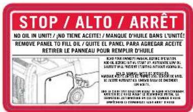
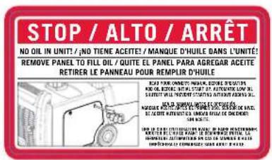
Add Engine Oil

CAUTION
DO NOT attempt to crank or start the engine before it has been properly filled with the recommended type and amount of oil. Damage to the generator as a result of failure to follow these instructions will void your warranty.

NOTE
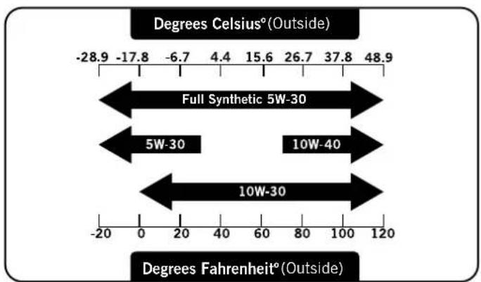
The recommended oil type is 10W-30 automotive oil.
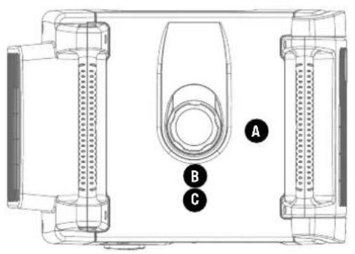
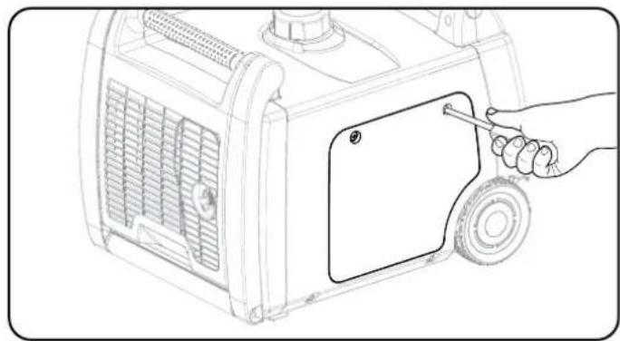
- Place the generator on a flat, level surface.
- Loosen the cover screws and remove the maintenance cover.
natural_image
Line drawing of a car air conditioner unit with a hand holding a screwdriver inserted into the door (no text or symbols)- Remove oil fill cap/dipstick to add oil.
- Add oil and replace oil fill cap/dipstick. DO NOT OVERFILL.
- Check engine oil level daily and add as needed.

NOTE
Once oil has been added, a visual check should show oil about 1-2 threads from running out of the fill hole. If using the dipstick to check oil level, DO NOT screw in the dipstick while checking.

NOTE
Check oil often during the break-in period. Refer to the Maintenance section for recommended service intervals.
Add Engine Oil Cont'd.
other
| Category | Value | |---|---| | Full Synthetic 5W-30 | -28.9 | | Full Synthetic 5W-30 | -17.8 | | Full Synthetic 5W-30 | -6.7 | | Full Synthetic 5W-30 | 4.4 | | Full Synthetic 5W-30 | 15.6 | | Full Synthetic 5W-30 | 26.7 | | Full Synthetic 5W-30 | 37.8 | | Full Synthetic 5W-30 | 48.9 | | 5W-30 | -20 | | 5W-30 | 0 | | 5W-30 | 20 | | 5W-30 | 40 | | 5W-30 | 60 | | 5W-30 | 80 | | 5W-30 | 100 | | 5W-30 | 120 | | 10W-40 | -20 | | 10W-40 | 0 | | 10W-40 | 20 | | 10W-40 | 40 | | 10W-40 | 60 | | 10W-40 | 80 | | 10W-40 | 100 | | 10W-40 | 120 | | 10W-30 | -20 | | 10W-30 | 0 | | 10W-30 | 20 | | 10W-30 | 40 | | 10W-30 | 60 | | 10W-30 | 80 | | 10W-30 | 100 | | 10W-30 | 120 | Degrees Celsius°(Outside) Degrees Fahrenheit°(Outside)CAUTION
The engine is equipped with a low oil shut-off and will stop when the oil level in the crankcase falls below the threshold level.

NOTE
The generator rotor has a sealed, pre-lubricated ball bearing that requires no additional lubrication for the life of the bearing.

NOTE
We consider the first 5 hours of run time to be the break-in period for the unit. During the break in period stay at or below 50% of the running watt rating and vary the load occasionally to allow stator windings to heat and cool. Adjusting the load will also cause engine speed to vary and help seat piston rings. After the 5 hour break-in period, change the oil.

NOTE
Synthetic oil may be used after the 5 hour initial break-in period. Using synthetic oil does not increase the recommended oil change interval.

NOTE
Weather will affect engine oil and engine performance. Change the type of engine oil used based on weather conditions to suit the engine needs.
Add Fuel (Petrol)
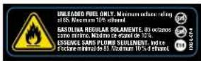
- Use clean, fresh, regular unleaded fuel with a minimum octane rating of 85 and an ethanol content of less than 10% by volume.
- DO NOT mix oil with fuel.
- Clean the area around the fuel cap.
- Remove the fuel cap.
- Slowly add fuel to the tank. DO NOT OVERFILL. Fuel can expand after filling. A minimum of 1/4 in. (6.4 mm) of space left in the tank is required for fuel expansion, more than 1/4 in. (6.4 mm) is recommended. Fuel can be forced out of the tank as a result of expansion if it is overfilled, and can affect the stable running condition of the product. When filling the tank, it is recommended to leave enough space for the fuel to expand.
- Screw on the fuel cap and wipe away any spilled fuel.

CAUTION
Use regular unleaded petrol with a minimum octane rating of 85.
Do not mix oil and petrol.
Fill tank to approximately 1/4 in. (6.4 mm) below the top of the tank to allow for fuel expansion.
DO NOT pump petrol directly into the generator at the petrol station. Use an approved container to transfer the fuel to the generator.
DO NOT fill fuel tank indoors.
DO NOT fill fuel tank when the engine is running or hot.
DO NOT overfill the fuel tank.
DO NOT light cigarettes or smoke when filling the fuel tank.

WARNING
Pouring fuel too fast through the fuel screen may result in blow back of fuel at the operator while filling.
Add Fuel Cont'd.

NOTE
Our engines work well with 10% or less ethanol blend fuels. When using blended fuels there are some issues worth noting:
- Ethanol-petrol blends can absorb more water than petrol alone.
- These blends can eventually separate, leaving water or a watery goo in the tank, fuel valve and carburetor.
- With gravity-fed fuel supplies, this compromised fuel can be drawn into the carburetor and cause damage to the engine and/or potential hazards.
– There are only a few suppliers of fuel stabilizer that are formulated to work with ethanol blend fuels.
– Any damages or hazards caused by using improper fuel, improperly stored fuel, and/or improperly formulated stabilizers, are not covered by manufacture's warranty.
It is advisable to always shut off the fuel supply, run the engine to fuel starvation and drain the tank when the equipment is not in use for more than 30 days.
Connecting the Propane (LPG) Cylinder
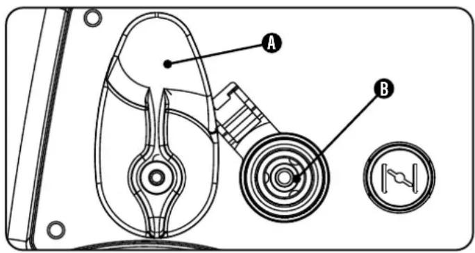
- Make sure the fuel selector switch on the inverter is in the 12 o'clock (vertical) position. (A)
- Using your fingers, slide the outer barrel back on the LPG quick connect hose fitting (B).
- While the outer barrel is in the back position, insert the LPG hose (included) into the inlet and release the outer barrel. The barrel will automatically return and lock the hose in the inlet.
- Remove the safety plug or cap from the cylinder valve.
- Attach the other end of the hose to the LPG cylinder and hand tighten.
- Check all connections for leaks by wetting the fittings with a solution of soap and water. Bubbles which appear or bubbles which grow indicate that a leak exists. If a leak exists at a fitting then turn off the gas valve at the tank and tighten the fitting. Turn the gas back on and recheck the fitting with the soap and water solution. If the leak continues or if the leak is not at a fitting then do not use the generator and contact customer service.
text_image
Technical diagram of a mechanical device with labeled parts A and B, showing internal components and a circular indicator.
NOTE
- Use only standard 20 or 30 pound capacity LP tanks with Type 1, right hand Acme threads.
- Verify the requalification date on the tank has not expired.
- All new cylinders must be purged of air and moisture prior to filling. Used cylinders that have not been plugged or kept closed must also be purged.
- The purging process should be done by a LPG supplier. (Cylinders from an exchange supplier should have been purged and filled properly already).
- Always position the cylinder so the connection between the valve and the gas inlet won't cause sharp bends or kinks in the hose.
Connecting LPG Cylinder Cont'd.
CAUTION
Do not allow children to tamper or play with the cylinder or hose connections.

CAUTION
Use approved LPG cylinders equipped with an OPD (overfilling prevention device) valve. Always keep the cylinder in a vertical position with the valve on top and installed at ground level on a flat surface. Cylinders must not be installed near any heat source and should not be exposed to sun, rain, and dust. When transporting and storing, turn off the cylinder valve and fuel valve, and disconnect the cylinder. Plug the outlet, usually by a plastic protective cap, if one is available. Keep cylinders away from heat and ventilated when in a vehicle.

WARNING
If there is a strong smell of gas: Close off the gas supply at the cylinder. Use soapy water, which will produce a large bubble at the point of any leak, to check the hose, and connections on the cylinder valve and the generator. Do not smoke or light a cigarette, or check for leaks using a match, open flame source or lighter. Contact a qualified technician to inspect and repair the LPG system if a leak is found, before using the generator.
Grounding
Your generator must be properly connected to an appropriate ground to help prevent electric shock.

WARNING
Failure to properly ground the generator can result in electric shock.
A ground terminal connected to the frame of the generator has been provided on the power panel. For remote grounding, connect of a length of heavy gauge
(12 AWG minimum) copper wire between the generator ground terminal and a copper rod driven into the ground. We strongly recommend that you consult with a qualified electrician to ensure compliance with local electrical codes.
Generator Location
NEVER operate the generator inside any building, including garages, basements, crawlspaces and sheds, enclosure or compartment, including the generator compartment of a recreational vehicle. Please consult your local authority. In some areas, generators must be registered with the local utility. Generators used at construction sites may be subject to additional rules and regulations. Generators should be on a flat, level surface at all times (even while not in operation). Generators must have at least 5 ft. (1.5 m) of clearance from all combustible material. In addition to clearance from all combustible material, generators must also have at least 3 ft. (91.4 cm) of clearance on all sides to allow for adequate cooling, maintenance and servicing. Generators should never be started or operated in the back of a SUV, camper, trailer, in the bed of a truck (regular, flat or otherwise), under staircases/stairwells, next to walls or buildings, or in any other location that will not allow for adequate cooling of the generator and/or the muffler. DO NOT contain generators during operation. Allow generators to properly cool before transport or storage. Place the generator in a well-ventilated area. DO NOT place the generator near vents or intakes where exhaust fumes could be drawn into occupied or confined spaces. Carefully consider wind and air currents when positioning generator.
Failure to follow proper safety precautions may void manufacturer's warranty.

WARNING
Do not operate or store the generator in rain, snow, or wet weather.
Using a generator or electrical appliance in wet conditions, such as rain or snow, or near a pool or sprinkler system, or when your hands are wet, could result in electrocution.

WARNING
During operation the muffler and exhaust fumes produced will become hot. If adequate cooling and breathing space are not supplied, or if the generator is blocked or contained, temperatures can become extremely heated and may lead to fire.
Grounding
The generator system ground connects the frame to the ground terminals on the power panel. The system ground is connected to the AC neutral wire.
Fuel Selector Switch
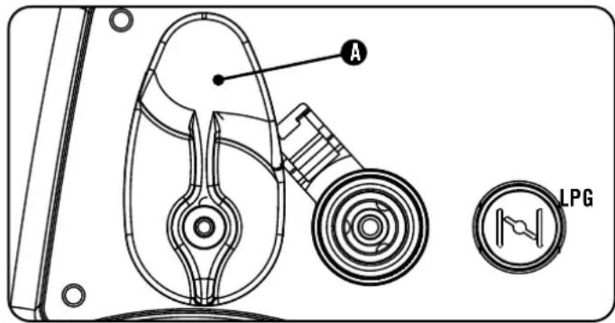
The fuel selector switch on the front panel of the inverter is designed to choose the desired fuel source–Petrol or LPG. To select the desired fuel source, simply rotate the selector switch to the fuel symbol on the panel. Turn the fuel selector switch to the 12 o'clock (vertical) position for LPG operation. (A)
text_image
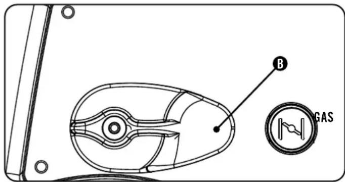
A LPGTurn the fuel selector switch to the 3 o'clock (horizontal) position for petrol operation. (B)
text_image
B GAS
NOTE
When the fuel selector switch is in the 3 o'clock position, the petrol fuel valve is OPEN. To CLOSE the petrol fuel valve, turn the selector switch to the 12 o'clock position.
CAUTION
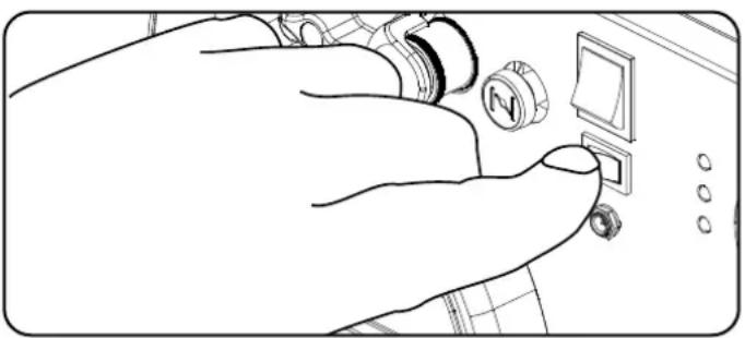
If the ignition switch is held down in the "Start" position longer than 5 seconds it could damage the starter.

NOTE
The supplied 12V 7AH battery does re-charge while the engine is running, but it is also recommended that the battery be fully charged at least once per month.

NOTE
When the battery switch is in the "ON" position, the switch will light up if the battery is sending out a charge. If the switch does not light up while in the "ON" position, check that the battery connection is still good.

NOTE
If the engine starts but does not continue to run make certain that the generator is on a flat, level surface. The engine is equipped with a low oil sensor that will prevent the engine from running when the oil level falls below a critical threshold.
PetrolStarting the Inverter

NOTE
The generator will NOT START with petrol without battery charge or an appropriate connection.
- Make certain the generator is on a flat, level surface.
- Disconnect all electrical loads from the generator. Never start or stop the generator with electrical devices plugged in or turned on.
- Turn the fuel selector switch to the "Horizontal" position.
- Pull the choke out to the "CHOKE" position.
- Push the ignition switch to the "ON" position.
- Push the battery switch to the "ON" position.
- ELECTRIC START: Press and hold the ignition switch to the "START" position. Release as the engine begins to start. If the engine fails to start within five seconds, release the switch and wait at least ten seconds before attempting to start the engine again.
- RECOIL START: Pull the starter cord slowly until resistance is felt and then pull rapidly.
- Do not over-choke. Allow the engine to warm up several seconds before gradually pushing the choke to the "RUN" position..

NOTE
Keep choke in “Choke” position for only 1 pull of the recoil starter. After first pull, push choke in for up to the next 3 pulls of the recoil starter. Too much choke leads to sparkplug fouling/engine flooding due to the lack of incoming air. This will cause the engine not to start.
LPG
- Make certain the generator is on a flat, level surface.
- Disconnect all electrical loads from the generator. Never start or stop the generator with electrical devices plugged in or turned on.
- Turn the fuel selector switch to the "Vertical" position and connect LPG hose.
- Fully open the LPG cylinder fuel knob.
- Push the ignition switch to the "ON" position.
- Push the battery switch to the "ON" position.
- ELECTRIC START: Pull the choke to the "Choke" position.
- Press and hold the ignition switch to the "START" position. Release as the engine begins to start. If the engine fails to start within five seconds, release the switch and wait at least ten seconds before attempting to start the engine again.
- Do not over-choke. Allow the engine to warm up several seconds before gradually pushing the choke to the "RUN" position.
- RECOIL START: Pull the choke to the "Choke" position.
- PULL-TO-PRIME: Pull the starter cord slowly until resistance is felt and then pull rapidly. Pull with choke out 1-2 times until you feel a few combustion pulses that indicates that the engine momentarily started.
- Push the choke in.
- Pull the starter cord slowly until resistance is felt and then pull rapidly.
- If engine fails to start in 1-pull with choke in the "RUN" position, then pull choke out and repeat the PULL-TO-PRIME step.
Starting LPG Cont'd.

NOTE
Observing frost on LPG containers and regulators is common during operation and normally is not an indication of a problem. As LPG vaporizes and travels from the tank to the generator engine it expands. The amount of frost that forms can be affected by the size of the container, the amount of fuel being used, the humidity of the air and other operating conditions. In unusual situations this frost may eventually restrict the flow of gas to the generator resulting in deteriorating performance. For example, if the tank temperature is reduced to a very low level then the rate at which the LPG vaporizes is also reduced and may not provide sufficient fuel flow to the engine. This is not an indication of a problem with the generator but only a problem with the flow of gas from the LPG container. If generator performance seems to be deteriorating at the same time that ice formation is observed on tank valve, hose or regulator then some actions may be taken to eliminate this symptom. In these rare situations it can be helpful to reduce or eliminate the cold fuel system effects by doing one of the following:
- Exchanging fuel tanks to allow the first tank to warm up, repeating as necessary
- Placing the LPG container at the end of the generator near the handle, where engine fan air flows out from the generator. This air is slightly heated by flowing over the engine. The container should not be placed in the path of the muffler outlet.
- The container can be temporarily warmed by pouring warm water over the top of the tank.
Economy Control Switch
The Economy Control switch can be activated in order to minimize fuel consumption and noise while operating the unit during times of reduced electrical output, allowing the engine speed to idle during periods of non-use. The engine speed returns to normal when an electrical load is connected. When the economy switch is off, the engine runs at normal speed continuously.
natural_image
Line drawing of a hand pressing down on a device with buttons and a screen (no text or symbols)! WARNING
For periods of high electrical load or momentary fluctuations, the Economy Control Switch should be turned OFF.
12V DC Outlet
The 12V DC outlet can be used with the supplied charge cable and USB charger and other commercially available 12V DC automotive style plugs. The DC output is unregulated and can damage some products. Confirm your accessory input voltage range is at least 12-24V DC. When using the DC outlet turn the Economy mode switch to the “OFF” position.
! WARNING
Do not operate a device while it is plugged in to the 12V DC outlet.
Prolonged exposure to engine exhaust can cause serious injury or death.
WARNING
While charging a device do not place on the exhaust side of the generator. Extreme heat caused by exhaust can damage the device, and cause a potential fire hazard.
Connecting Electrical Loads
- Let the engine stabilize and warm up for a few minutes after starting
- Plug in and turn on the desired 240 (UK model) or 220 (EU model) Volt AC single phase, 50 Hz electrical loads.
- DO NOT connect 3-phase loads to the generator.
- DO NOT overload the generator.
NOTE
Connecting a generator to your electric utility company's power lines or to another power source may be against the law. In addition this action, if done incorrectly, could damage your generator and appliances and could cause serious injury or even death to you or a utility worker who may be working on nearby power lines. If you plan to run a portable electric generator during an outage, please notify your electric utility company immediately and remember to plug your appliances directly into the generator. Do not plug the generator into any electric outlet in your home. Doing so could create a connection to the utility company power lines. You are responsible for ensuring that your generator's electricity does not feed back into the electric utility power lines.
If the generator will be connected to a building electrical system, consult your local utility company or a qualified electrician. Connections must isolate generator power from utility power and must comply with all applicable laws and codes.
Parallel Operation
Two (2) Champion model 73001I-DF (EU) generators can be operated in parallel to increase the total available electrical power. A Champion model CPGPARKIT3K parallel kit (optional equipment) is required for parallel operation. For kit availability, call customer service at your local dealer.
Detailed instructions for parallel kit installation and operation of the connected generators are provided in the parallel kit owner's manual and operating instructions.
Do Not Overload Generator
Capacity
Follow these simple steps to calculate the running and starting watts necessary for your purposes.
- Select the electrical devices you plan on running at the same time.
- Total the running watts of these items. This is the amount of power you need to keep your items running.
- Identify the highest starting wattage of all devices identified in step 1. Add this number to the number calculated in step 2. Surge wattage is the extra burst of power needed to start some electric driven equipment. Following the steps listed under “Power Management” will guarantee that only one device will be starting at a time.
Power Management
Use the following formula to convert voltage and amperage to watts:
$$ \text { Volts } \times \text { Amps } = \text { Watts } $$
To prolong the life of your generator and attached devices, follow these steps to add electrical load:
- Start the generator with no electrical load attached.
- Allow the engine to run for several minutes to stabilize.
- Plug in and turn on the first item. It is best to attach the item with the largest load first.
- Allow the engine to stabilize.
- Plug in and turn on the next item.
- Allow the engine to stabilize.
- Repeat steps 5-6 for each additional item.

NOTE
Never exceed the specified capacity when adding loads to the generator.
Stopping the Engine
- Turn off and unplug all electrical loads. Never start or stop the generator with electrical devices plugged in or turned on.
- Let the generator run at no-load for several minutes to stabilize internal temperatures of the engine and generator.
- Turn the Fuel Valve to the "OFF" position if operating by petrol.
- Turn the LPG cylinder knob to the "CLOSE" or off position if operating by LPG.
- Let the engine run until fuel starvation has stopped the engine. This usually takes a few minutes.
- Press the ignition switch to the "OFF" position.
- Turn battery switch to the "Off" Position.
Important: Always ensure that the fuel valve and the ignition switch are in the "OFF" position when the engine is not in use.

NOTE
When turning off the generator after LPG operation, make sure the LPG cylinder knob is in the fully closed position.

NOTE
If the engine will not be used for a period of two (2) weeks or longer, please see the Storage section for proper engine and fuel storage.

NOTE
Always turn the battery switch to the “OFF” position when unit is not in use, this will stop the battery from being drained. Follow the maintenance and storage instructions for the generator and battery when the unit will not be used for a period of 2 weeks or more.
Operation at High Altitude
The density of air at high altitude is lower than at sea level. Engine power is reduced as the air mass and air-fuel ratio decrease. Engine power and generator output will be reduced approximately 3½% for every 1000 ft. of elevation above sea level. This is a natural trend and cannot be changed by adjusting the engine. At high altitudes increased exhaust emissions can also result due to the increased enrichment of the air fuel ratio. Other high altitude issues can include hard starting, increased fuel consumption and spark plug fouling.
Overload Operation
The overload indicator light will turn on when the rated load is exceeded. When the maximum load is reached, the LED will blink and cut power to the receptacles. To recover the power, shut down the engine, wait until the light turns off and restart the generator.
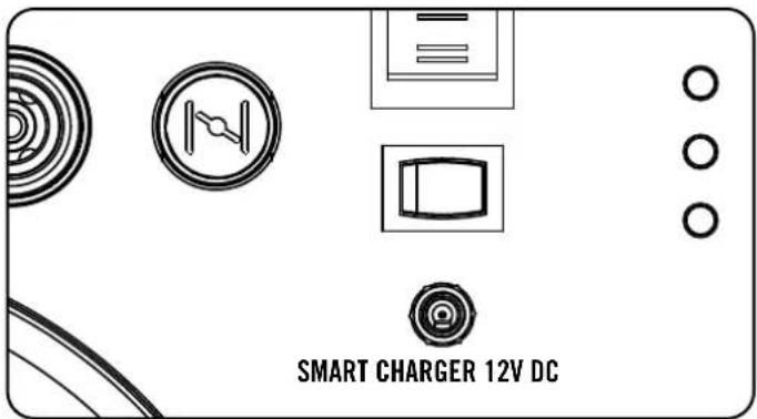
Smart Charger
The smart charger (included) is a device that is used to charge the generator battery. The smart charger plugs into the generator, into the DC input on the front panel, and then into a household outlet power source. There is a light on the charger. If the battery is in need of a charge or charging then the red light will light up. If the battery is good and not in need of charging or has completed charging then the green light will light up. The smart charger is programmed not to charge or to stop charging when the light is green. This is a safety feature that will help prevent damage to the battery and generator.
text_image
SMART CHARGER 12V DCNOTE
If the battery is completely dead, and won't hold a charge, then the smart charger can be plugged into a power source to enable power to the choke.
The owner/operator is responsible for all periodic maintenance.

WARNING
Never operate a damaged or defective generator.

WARNING
Tampering with the factory set governor will void your warranty.

WARNING
Improper maintenance will void your warranty.

NOTE
Maintenance, replacement, or repair of emission control devices and systems may be performed by any non-road engine repair establishment or individual.
Complete all scheduled maintenance in a timely manner. Correct any issue before operating the generator.
Engine Maintenance
To prevent accidental starting, remove and ground spark plug wire before performing any service.
Oil
Change oil when the engine is warm. Refer to the oil specification to select the proper grade of oil for your operating environment.
- Set the generator on top of a work bench or table.
- Loosen the cover screws and remove the maintenance cover.
- Pop up the rubber maintenance plug, from below the drain bolt.
- Remove the drain bolt.
- Tilt the generator on its side and allow the oil to drain completely.
- Replace the drain bolt.
- Add standard engine oil and replace oil fill cap/dipstick. DO NOT OVERFILL.
Oil Cont'd.
- Reinstall the maintenance cover and tighten the cover screws.
- Dispose of used oil at an approved waste management facility.

NOTE
Once oil has been added, a visual check should show oil about 1-2 threads from running out of the fill hole. If using the dipstick to check oil level, DO NOT screw in the dipstick while checking.

text_image
MAXIMUM FILL MINIMUM FILL DIP STICK DRAIN PLUGSpark Plugs
- Remove the spark plug cable from the spark plug.
- Use a spark plug socket tool or socket (not included) to remove the plug.
- Inspect the electrode on the plug. It must be clean and not worn to produce the spark required for ignition.
- Make certain the spark plug gap is 0.55 - 0.65 mm or (0.021 - 0.025 in.).
- Refer to the spark plug recommendation chart when
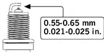
text_image
0.55-0.65 mm 0.021-0.025 in.replacing the plug.
-
Carefully thread the plug into the engine.
-
Use the spark plug socket (not included) to firmly install the plug.
-
Attach the spark plug wire to the plug.
73001i-DF(EU)
OEM spark plug: F7RTC
Replacement spark plug: NGK BPR6ES or equivalent Make certain the *spark plug gap is 0.55 - 0.65 mm or (0.021 - 0.025 in.).
Maintenance Valve Clearance
- Intake: 0.06 - 0.12 mm (0.002 - 0.005 in.)
- Exhaust: 0.08 - 0.14 mm (0.003 - 0.006 in.)
Air Filter
- Remove the maintenance cover.
- Locate the air filter plastic cover.
- Unsnap the locking hinge on the cover.
- Remove the old filter.
- Place the new filter in the assembly.
- Re-snap the hinge on the air filter cover.
- Reinstall the maintenance cover and tighten the cover screw securely.
Cleaning
! CAUTION
DO NOT spray generator with water.
Water can contaminate the fuel system.
Use a damp cloth to clean exterior surfaces of the generator.
Use a soft bristle brush to remove dirt and oil.
Use an air compressor (25 PSI) to clear dirt and debris from the generator.
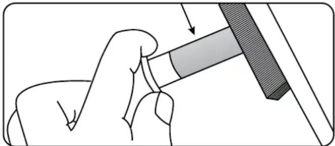
Spark Arrester
- Allow the engine to cool completely before servicing the spark arrester.
- Remove the two screws holding the cover plate which retains the end of the spark arrester to the muffler.
- Remove the spark arrester screen.
- Carefully remove the carbon deposits from the spark arrester screen with a wire brush.
- Replace the spark arrester if it is damaged.
- Position the spark arrester in the muffler and attach with the two screws.
natural_image
Illustration of a hand holding a tool with a shaded component, no text or symbols presentCAUTION
Failure to clean the spark arrester will result in degraded engine performance.
Adjustments
The air-fuel mixture is not adjustable. Tampering with the governor can damage your generator and your electrical devices and will void your warranty.
Maintenance Schedule
Follow the service intervals indicated in the following maintenance schedule.
Service your generator more frequently when operating in adverse conditions.
| Every 8 hours or daily | |
| Check oil level | |
| Clean around air intake and muffler | |
| Check hoses for leaks | |
| First 5 hours | |
| Change oil | |
| Every 50 hours or every season | |
| Clean air filter | |
| Change oil if operating under heavy load or in hot environments | |
| Every 100 hours or every season | |
| Change oil | |
| Clean/Adjust spark plug | |
| Check/Adjust valve clearance* | |
| Clean spark arrester | |
| Clean fuel tank and filter* | |
| Every 250 hours | |
| Clean combustion chamber* | |
| Every 3 years | |
| Replace fuel line and LPG hose | |
*To be performed by knowledgeable, experienced owners or Champion Power Equipment certified dealers.
Generator Battery
This product is equipped with an automatic battery charging circuit. The battery will receive charging voltage when the engine is running. The battery will maintain a proper charge if the unit is used on a regular basis (about once every two weeks). If it is used less frequently, the battery should be connected to a trickle charger (included) or battery maintainer to keep the battery properly charged. If the battery is not able to start the engine, it can be started by manually pulling the engine recoil cord. If the battery voltage is extremely low, the charging circuit may not be able to re-charge the battery. In this case, the battery must be connected to a standard automotive style battery charger for re-charging before it can be used.
Charge the Battery
For a generator equipped with batteries for electric starting, proper battery maintenance and storage should be followed. An automatic battery charger (included) with automatic charging capability should be used to charge the battery. Maximum charging rate should not exceed 1.5 amps. Follow the instructions included with the battery charger. The battery should be fully charged at least once per month.

NOTE
A Float Charger will maintain the battery condition over long storage periods.
Disconnect the Battery
- Remove the battery panel cover.
- Remove the protective cover from the black/negative battery lead.
- Disconnect the black/negative lead from the black/negative terminal on the battery and store the cap screw and nut.
- Repeat steps 1-2 for the red/positive battery lead.
- Store the battery in a cool, dry place.
Generator Maintenance
Make certain that the generator is kept clean and stored properly. Only operate the unit on a flat, level surface in a clean, dry operating environment. DO NOT expose the unit to extreme conditions, excessive dust, dirt, moisture or corrosive vapours.
Use a damp cloth to clean exterior surfaces of the generator.
Use a soft bristle brush to remove dirt and oil.
Use an air compressor (25 PSI) to clear dirt and debris from the generator.
Inspect all air vents and cooling slots to ensure that they are clean and unobstructed.

CAUTION
DO NOT use a garden hose to clean the generator.
Water can enter the generator through the cooling slots and damage the generator windings.
Storage
The generator should be started at least once every
14 days and allowed to run for at least 20 minutes.
For longer term storage, please follow these guidelines.
Generator Storage
- Add a properly formulated fuel stabilizer to the tank.
- Be sure all appliances are disconnected from the generator.
- Run the generator for a few minutes so the treated fuel cycles through the fuel system and carburetor.
- Turn the fuel valve to the "Off" position.
- Let the generator run until fuel starvation has stopped the engine. This usually takes a few minutes.
- The generator needs to cool completely before cleaning and storage.
- Remove the spark plug cap, then pull the recoil grip 3 times to drain the petrol from the carburetor jets.
- Change the engine oil.
- Remove the spark plug and pour about a tablespoon of oil into the cylinder. Crank the engine slowly to distribute the oil and lubricate the cylinder.
- Reattach the spark plug.
- Store the unit in a clean, dry place out of direct sunlight.

DANGER
Generator exhaust contains odorless and colorless carbon monoxide gas.
To avoid accidental or unintended ignition of your electric start generator during periods of storage, the following precautions should be followed:
- When storing the generator for short periods of time make sure that the ignition switch, the fuel valve and the battery switch are set in the OFF position.
- When storing the generator for extended periods of time make sure that the ignition switch, the fuel valve and the battery switch are set in the the OFF position and the battery leads have been disconnected from the battery.
| Problem Cause Solution | ||
| Generator will not start No fuel Add fuel | ||
| Faulty spark plug Replace spark plug | ||
| Unit loaded during start up Remove load from unit | ||
| Generator will not start; Generator starts but runs roughly | Low oil level Fill crankcase to the proper level | |
| Place generator on a flat, level surface | ||
| Choke in the wrong position Adjust choke | ||
| Spark plug wire loose Attach wire to spark plug | ||
| Generator will not start electrically Generator | battery is dead Recharge generator battery | |
| Battery switch is in the “OFF” position Turn battery switch to “ON” position | ||
| Generator shuts down during operation | Out of fuel | Fill fuel tank |
| Low oil level Fill crankcase to the proper level. Place generator on a flat, level surface | ||
| Generator cannot supply enough power or overheating | Generator is overloaded | Review load and adjust. See “Power Management” |
| Insufficient ventilation | Check for air restriction. Move to a well ventilated area | |
| No AC output | Cable not properly connected | Check all connections |
| Connected device is defective | Replace defective device | |
| Circuit breaker is open | Reset circuit breaker | |
| Loose wiring | Inspect and tighten wiring connections | |
| Other | Contact the help line | |
| Repeated circuit breaker tripping | Overload | Review load and adjust. See “Power Management” |
| Faulty cords or device | Check for damaged, bare or frayed wires. Replace defective device | |
Introduktion
natural_image
Line drawing of a portable electric vehicle with a side panel and fan (no text or symbols)Ansluta batteriet, forts.

OBSERVERA
natural_image
Line drawing of a portable air conditioner unit with a hand holding a tool, no text or symbols presentother
| Category | Value | |---|---| | Full Synthetic 5W-30 | -28.9 | | Full Synthetic 5W-30 | -17.8 | | Full Synthetic 5W-30 | -6.7 | | Full Synthetic 5W-30 | 4.4 | | Full Synthetic 5W-30 | 15.6 | | Full Synthetic 5W-30 | 26.7 | | Full Synthetic 5W-30 | 37.8 | | Full Synthetic 5W-30 | 48.9 | | 5W-30 | -20 | | 5W-30 | 0 | | 5W-30 | 20 | | 5W-30 | 40 | | 5W-30 | 60 | | 5W-30 | 80 | | 5W-30 | 100 | | 5W-30 | 120 | | 10W-40 | -20 | | 10W-40 | 0 | | 10W-40 | 20 | | 10W-40 | 40 | | 10W-40 | 60 | | 10W-40 | 80 | | 10W-40 | 100 | | 10W-40 | 120 | | 10W-30 | -20 | | 10W-30 | 0 | | 10W-30 | 20 | | 10W-30 | 40 | | 10W-30 | 60 | | 10W-30 | 80 | | 10W-30 | 100 | | 10W-30 | 120 | | Degrees Fahrenheit° (Outside) | -20 | | Degrees Fahrenheit° (Outside) | 0 | | Degrees Fahrenheit° (Outside) | 20 | | Degrees Fahrenheit° (Outside) | 40 | | Degrees Fahrenheit° (Outside) | 60 | | Degrees Fahrenheit° (Outside) | 80 | | Degrees Fahrenheit° (Outside) | 100 | | Degrees Fahrenheit° (Outside) | 120 | Degrees Celsius° (Outside) Degrees Fahrenheit° (Outside)FÖRSIKTIGHET
text_image
Technical diagram of a mechanical device with labeled parts A and B, showing internal components and a circular component.
NOTE
Starta gasol, forts.

OBSERVERA
natural_image
Line drawing of a hand pressing down on a device with a knob and control panel (no text or symbols)
WARNING
text_image
SMART LADDARE 12 V DC
OBSERVERA
natural_image
Illustration of a hand holding a tool with a shaded component, no text or symbols present
FÖRSIKTIGHET
natural_image
Technical line drawing of a mechanical component with labeled parts A, B, and C (no text or symbols beyond labels)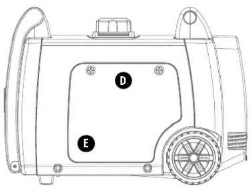
text_image
D E
natural_image
Technical line drawing of a portable air conditioner unit with ventilation grilles and fan (no text or symbols)A

text_image
15M MINI MOUNT OF SPACE MINI PHARMACE TRAMICE 5.6M RESISTED WITH THE OWN IN THE WB

©
text_image
DANGER Using a generator in the carer CAM KILL YOM CONTENTS. Cigarette every containable carbon monoxide. This is a person you cannot use or smell. NEVER US MELON LE GOURG EVEN FLORE and windows are open. ONLY US OUTSIDE in the carer windows, drive, and words. PELIGRO E use de un generator en la leitores PUEDE MATARLO EN MINUTOS. E escape del generator continue monoxide de carbono. Cable en un aspenso que me se pueled ver a cer. RUNICA In case destinir del hogar en el garaje, INCLISO Si las puertas y ventillas mean acueritas. Esles SOLD EN INTERPREM LEQ DE VENTOS, puertas, y voltas de entecidos. DANGER Ussiner un generator à l'inéprime PEOT VOUS TOUR EN QUELOUES MÉNUTES. L'échopement du generator content du moulez le plus des carbons. Et c'est un person que vous ne pouvée ni ne vceant. A une type d'ANALIS qui la mouten de garaje. MEINE Si les parties en les frâmites sont courantes. Utilisés non uniUMÉNET À L'EXTENIER, sur des tenches, portes de trapeaux de ventilation.D

text_image
DANGER PELIGRO WARNING ADVERTENCIA CAUTION PRECAUCIONE
text_image
STOP / ALTO / ARRÊT NO OIL IN UNIT / NO TIENE ACEITE / MANQUE D'HYULIE DANS L'UNITÉ REMOVE PANEL TO FILL OIL / QUITE EL PANEL PARA AGREGAR ACEITE RETIRER LE PANNEAU POUR REMPLIR D'HYULIE RARE PAR MOUNT ET DELENTATION RARE PAR MOUNT ET DELENTATION PAR MOUNT ET DELENTATION PAR MOUNT ET DELENTATION PAR MOUNT ET DELENTATION PAR MOUNT ET DELENTATION PAR MOUNT ET DELENTATION PAR MOUNT ET DELENTATION PAR MOUNT ET DELENTATION PAR MOUNT ET DELENTATION PAR MOUNT ET DELENTATION PAR MOUNT ET DELENTATION PAR MOUNT ET DELENTATION PARMEN : 10000000000000000000000000000000000000000000000000000000000000000000000000000000000000000000000000000 PAR MOUNT ET DELENTATION PAR MOUNT ET DELENTATION PAR MOUNT ET DELENTATION PAR MOUNT ET DELENTATION PAR MOUNT ET DELENTATION PAR MOUNT ET DELENTATION PAR MOUNT ET DELENTATION PAR MOUNT ET DELENTATION PAR MOUNT ET DELENTATION PAR MOUNT ET DELENTATION PAR MOUNT ET DELENTATIONF

natural_image
Technical line drawing of a mechanical device with no visible text or symbolsnatural_image
Line drawing of a car air conditioner unit with a hand holding a screwdriver inserted into the door (no text or symbols)text_image
Technical diagram of a mechanical device with labeled parts A and B, showing internal components and a circular symbol.
HINWEIS
natural_image
Line drawing of a hand pressing down on a device with buttons and a screen (no text or symbols)
WARNUNG
Volt x Ampere = Watt
natural_image
Technical line drawing of a portable air conditioner unit with cooling fan and ventilation slots (no text or symbols)sammen.
- Bruk en skrutrekker til å skru av batteribolten i den røde, positive (+) batteriterminalen.
- Koble den røde, positive (+) ledningen til den positive (+) terminalen på batteriet ved hjelp av bolten.
- Dra gummihylsen over batterikabeltilkoblingen og batteriterminalen.
- Gjenta trinn 5-7 for den sorte, negative (-) batteriledningen og den sorte, negative (-) batteriterminalen.
natural_image
Line drawing of a car air conditioner unit with a hand holding a screwdriver (no text or symbols)text_image
Technical diagram of a mechanical device with labeled components A and B, showing internal components and a circular component.
MERKNAD
natural_image
Line drawing of a hand pressing down on a device with buttons and a screen (no text or symbols)
ADVARSEL
natural_image
Illustration of a hand holding a tool with a shaded component, no text or symbols present
FORSIKTIG
natural_image
Technical line drawing of a mechanical component with labeled parts A, B, and C (no text or symbols beyond labels)
text_image
D E
natural_image
Technical line drawing of a portable air conditioner unit with ventilation grilles and fan (no text or symbols)A

text_image
1.5M MINIMUM OF SERVICE MINIMUM GECRAM S.E.T. 1.5M ES 30 DE 2010 WB

C

natural_image
Technical line drawing of a portable air purifier with cooling unit and side panel (no text or symbols)natural_image
Line drawing of a mechanical device with a hand holding a screwdriver inserted into a component (no text or symbols)bar
Degrees Celsius° (Outside) | Category | Value | |---|---| | Full Synthetic 5W-30 | -28.9 | | Full Synthetic 5W-30 | -17.8 | | Full Synthetic 5W-30 | -6.7 | | Full Synthetic 5W-30 | 4.4 | | Full Synthetic 5W-30 | 15.6 | | Full Synthetic 5W-30 | 26.7 | | Full Synthetic 5W-30 | 37.8 | | Full Synthetic 5W-30 | 48.9 | | 5W-30 | -20 | | 5W-30 | 0 | | 5W-30 | 20 | | 5W-30 | 40 | | 5W-30 | 60 | | 5W-30 | 80 | | 5W-30 | 100 | | 5W-30 | 120 | | 10W-40 | -20 | | 10W-40 | 0 | | 10W-40 | 20 | | 10W-40 | 40 | | 10W-40 | 60 | | 10W-40 | 80 | | 10W-40 | 100 | | 10W-40 | 120 | The chart displays a single horizontal bar for each category, with the full synthetic material shown as a separate bar extending beyond the bars.Degrees Fahrenheit ^° (Outside)
NOUDATA VAROVAISUUTTA
text_image
Technical diagram of a mechanical device with labeled parts A and B, including a circular component and a waveform symbol.
HUOMIO
text_image
A NESTEKAASUnatural_image
Line drawing of a hand pressing down on a device with a magnifying glass and buttons (no text or symbols)
VAROITUS
natural_image
Illustration of a hand holding a tool with a shaded component, showing a finger pressing a button (no text or symbols present)NOUDATA VAROVAISUUTTA
natural_image
Technical line drawing of a portable air conditioner unit with cooling fan and ventilation slots (no text or symbols)natural_image
Line drawing of a hand inserting a screwdriver into a car air vent (no text or symbols)other
| Range | Value | |---|---| | -28.9 to -17.8 | Full Synthetic 5W-30 | | -6.7 to -4.4 | 5W-30 | | 4.4 to 15.6 | 10W-40 | | 15.6 to 26.7 | 10W-30 | | 26.7 to 37.8 | 10W-30 | | 37.8 to 48.9 | 10W-30 | Degrees Celsius° (Outside) | Degrees Fahrenheit° (Outside)ETTEVAATUST
text_image
Technical diagram of a mechanical device with labeled parts A and B, showing internal components and a circular component.
NOTE
natural_image
Line drawing of a hand pressing down on a device with buttons and a screen (no text or symbols)
HOIATUS
natural_image
Illustration of a hand holding a tool with a shaded component, no text or symbols present
ETTEVAATUST
CHAMPION ELEKTRISEADMED
3 AASTA PIIRATUD GARANTII
Garantii nõuded
https://www.championpowerequipment.co.uk
text_image
Diagram illustrating the elimination of a car and its use in a garage, with no signage or text labels.natural_image
Technical line drawing of a vehicle chassis with wheels and a small rectangular component (no text or symbols)natural_image
Line drawing of a hand using a tool to adjust or install a component on a device (no text or symbols visible)text_image
Technical diagram of a mechanical device with labeled components A and B, including a circular component and a directional indicator.⚠ PRÉCAUTION
text_image
Technical diagram of a mechanical device with labeled component A and a circular control symbol belowtext_image
Technical diagram of a mechanical component with labeled parts and a circular control symbol
REMARQUE
natural_image
Line drawing of a hand pressing down on a device with buttons and a magnifying glass (no text or symbols)
AVERTISSEMENT
Make certain the *spark plug gap is 0.55 - 0.65 mm or
(0.021 - 0.025 in.)
Maintenance Valve Clearance
- Intake: 0.06 - 0.12 mm (0.002 - 0.005 in.)
- Exhaust: 0.08 - 0.14 mm (0.003 - 0.006 in.)
natural_image
Illustration of a hand holding a tool with a shaded component, no text or symbols present⚠ PRÉCAUTION
text_image
1.5M MINI MAJOR ITEMS PAG E MINI MAJOR ITEMS PAG E SET OF 20 MINI PEET 1.5MB

©
text_image
DANGER Using a generator indoors CAN KILL YOU IN MINUTES. Generator prevent confiance carbon monoxide. This is a person you cannot see a smell. HEVER use the device a picture of garage, EVER IF I don't so, windows are open. ONLY USE OUTSIDE and far away from windings, doors, and vents. PELIGRO E-use de un generator en interiores PUEDE MATARLO EN MINUTOS. E escape del generator continue monoxide de carbone. Let be an asterisk que ne se puede ver in bed. NOGICA to use centre del tower in el garaje. ING.950-58 las puertas y ventarías estan alteradas. Leses 3641 A INTERPRENE, portes de ventarías, partidas, y a laores de ventilación. DANGER Uses un generator à l'intérieur PEUT VOUS TOUR EN QUELQUES MINUTES. Céchappement du generator contant du mille de la carce de carros. El a été un port de suave sur une distance et le mille de la garaje. NEME si les portes et les fenmines sont annuées. Intérêts à UNIQUIENMENT À L'EXTÉRIEUR, telles des fenmines, portes et lapres de ventilación.D
text_image
DANGER PREVENTIONAL CAPACITY FOR SUPERIOR CABBAGE AND PREVENTIONAL DURATION ABSTRACT STRESSING ASSEMBLIC, PROPRIETING ITEMS OF THE TEMPERATURE WITH FEETLE STRESSING ITEMS OF THE TEMPERATURE WITH THE PEACEER'S TOLERANCE. STRESSING ITEMS OF THE TEMPERATURE WITH THE PEACEER'S TOLERANCE. STRESSING ITEMS OF THE TEMPERATURE WITH THE PEACEER'S TOLERANCE. STRESSING ITEMS OF THE TEMPERATURE WITH THE PEACEER'S TOLERANCE. STRESSING ITEMS OF THE TEMPERATURE WITH THE PEACEER'S TOLERANCE. STRESSING ITEMS OF THE TEMPERATURE WITH THE PEACEER'S TOLERANCE. STRESSING ITEMS OF The TEMPERATURE WITH THE PEACEER'S TOLERANCE. STRESSING ITEMS OF THE TEMPERATURE WITH THE PEACEER'S TOLERANCE. STRESSING ITEMS OF THE TEMPERATURE WITH THE PEACEER'S TOLERANCE. STRESSING ITEMS OF THE TEMPERATURE WITH THE PEACEER'S TOLERANCE. STRESSING ITEMS OF THE TEMPERATURE WITH THE PEACEER'S TOLERANCE. STRESSING ITEMS OF THE TEMPERATURE WITH THE PEACEER'S TOLERANCE. WARNING PREVENTIONAL CAPACITY FOR SUPERIOR CABBAGE AND PREVENTIONAL DURATION ABSTRACT STRESSING ASSEMBLIC, PROPRIETING ITEMS OF THE TEMPERATURE WITH FEETLE STRESSING ITEMS OF THE TEMPERATURE WITH THE PEACEER'S TOLERANCE. STRESSING ITEMS OF THE TEMPERATURE WITH THE PEACEER'S TOLERANCE. STRESSING ITEMS OF THE TEMPERATURE WITH THE PEACEER'S T tolerANCE. STRESSING ITEMS OF THE TEMPERATURE WITH THE PEACEER'S TOLERANCE. STRESSING ITEMS OF THE TEMPERATURE WITH THE PEACEER'S TOLERANCE. STRESSING ITEMS OF THE TEMPERATURE WITH THE PEACEER'S TOLERANCE. STRESSING ITEMS OF THE TEMPERATURE WITH THE PEACEER'S TOLERANCE. STRESSING ITEMS OF THE TEMPERATURE WITH THE PEACEER'S TOLERANCE. STRESSNG PREVENTIONAL CAPACITY FOR SUPERIOR CABBAGE AND PREVENTIONAL DURATION ABSTRACT STRESSING ASSEMBLIC, PROPRIETING ITEMS OF THE TEMPERATURE WITH FEETLE STRESSING ITEMS OF THE TEMPERATURE WITH THE PEACEER'S TOLERANCE. STRESSING ITEMS OF THE TEMPERATURE WITH THE PEACEER'S TOLERANCE. STRESSING ITEMS OF THE TEMPERATURE WITH THE PEACEER'S TEREMENCE. STRESSING ITEMS OF THE TEMPERATURE WITH THE PEACEER'S TOLERANCE. STRESSING ITEMS OF THE TEMPERATURE WITH THE PEACEER'S TOLERANCE. STRESSING ITEMS OF THE TEMPERATURE WITH THE PEACEER'S TOLERANCE. STRESSING ITEMS OF THE TEMPERATURE WITH THE PEACEER'S TOLERANCE. STRESSING ITEMS OF THE TEMPERATURE WITH THE PEACEER'S TOLERANCE. STRESSING PREVENTIONAL CAPACITY FOR SUPERIOR CABBAGE AND PREVENTIONAL DURATION ABSTRACT STRESSING ASSEMBLIC, PROPRIETING ITEMS OF THE TEMPERATURE WITH FEETLE STRESSING ITEMS OF THE TEMPERATURE WITH THE PEACEER'S TOLERANCE. STRESSING ITEMS OF THE TEMPERATURE WITH THE PEACEER'S TOLERANCE. STRESSING ITEMS OF THE TEMPERATURE WITH THE PEACEER'S TTEREMENCE. STRESSING ITEMS OF THE TEMPERATURE WITH THE PEACEER'S TTEREMENCE. STRESSING ITEMS OF THE TEMPERATURE WITH THE PEACEER'S TTEREMENCE. STRESSING ITEMS OF THE TEMPERATURE WITH THE PEACEER'S TTEREMENCE. STRESSING ITEMS OF THE TEMPERATURE WITH THE PEACEER'S TTEREMENCE. STRESSING ITEMS OF THE TEMPERATURE WITH THE PEACEER'S TTEREMANCE. PREVENTIONAL CAPACITY FOR SUPERIOR CABBAGE AND PREVENTIONAL DURATION ABSTRACT STRESSING ASSEMBLIC, PROPRIETING ITEMS OF THE TEMPERATURE WITH FEETLE STRESSING ITEMS OF THE TEMPERATURE WITH THE PEACEER'S TOLERANCE. STRESSING ITEMS OF THE TEMPERATURE WITH THE PEACEER'S TTEREMENCE. STRESSING ITEMS OF THE TEMPERATURE WITH THE PEACEER'S TTEREMENCE. STRESSING ITEMS OF THE TEMPERATURE WITH THE PEACEER'S TTEREMENCE. STRESSING ITEMS OF THE TEMPERATURE WITH THE PEACEER'S TTEREMENCE. PREVENTIONAL CAPACITY FOR SUPERIOR CABBAGE AND PREVENTIONAL DURATION ABSTRACT STRESSING ASSEMBLIC, PROPRIETING ITEMS OF THE TEMPERATURE WITH FEETLE STRESSING ITEMS OF THE TEMPERATURE WITH THE PEACEER'S TOLERANCE. STRESSING ITEMS OF THE TEMPERATURE WITH THE PEACEER'S TTEREMENCE. STRESSING ITEMS OF THE TEMPERATURE WITH THE PEACEER'STTEREMENCE. STRESSING ITEMS OF THE TEMPERATURE WITH THE PEACEER'S TTEREMENCE. STRESSING ITEMS OF THE TEMPERATURE WITH THE PEACEER'S TTEREMENCE. PREVENTIONAL CAPACITY FOR SUPERIOR CABBAGE AND PREVENTIONAL DURATION ABSTRACT STRESSING ASSEMBLIC, PROPRIETING ITEMS OF THE TEMPERATURE WITH FEETLE STRESSING ITEMS OF THE TEMPERATURE WITH THE PENECEAN CABBAGE AND PREVENTIONAL DURATION ABSTRACT STRESSING ASSEMBLIC, PROPRIETING ITEMS OF THE TEMPERATURE WITH FEETLE STRESSING ITEMS OF THE TEMPERATURE WITH THE PENECEAN CABBAGE AND PREVENTIONAL DURATION ABSTRACT STRESSING ASSEMBLIC, PROPRIETING ITEMS OF THE TEMPERATURE WITH FEETLE STRESSING ITEMS OF THE TEMPERATURE WITH THE PENECEANE CABBAGE AND PREVENTIONAL DURATION ABSTRACT STRESSING ASSEMBLIC, PROPRIETING ITEMS OF THE TEMPERATURE WITH FEETLE STRESSING ITEMS OF THE TEMPERATURE WITH THE PENECEANE CABBAGE AND PREVENTIONAL DURATION ABSTRACT STRESSING ASSEMBLIC, PROPRIETING ITEMS OF THE TEMPERATURE WITH FEETLE STRESSING ITEMS OF THE TEMPERATURE WITH THE PENECEAN CABBAGE AND PREVENTIONAL DURATION ABSTRACT STRESSING ASSEMBLIC, PROPRIETING ITEMS OF THE TEMPERATURE WITH FEETLE STRESSING ITEMS OF THE TEMPERATURE WITH THE PENECEAE CABBAGE AND PREVENTIONAL DURATION ABSTRACT STRESSING ASSEMBLIC, PROPRIETING ITEMS OF THE TEMPERATURE WITH FEETLE STRESSING ITEMS OF THE TEMPERATURE WITH THE PENECEAE CABBAGE AND PREVENTIONAL DURATION ABSTRACT STRESSING ASSEMBLIC, PROPRIETING ITEMS OF THE TEMPERATURE WITH FEETLE STRESSING ITEMS OF THE TEMPERATURE WITH THE PENECEANE CABBAGE AND PREVENTIONAL DURATION ABSTRACT STRESSING ASSEMBLIC, PROPRIETING ITEMS OF THE TEMPERATURE WITH FEETLE STRESSING ITEMS OF THE TEMPERATURE WITH THE PENECEAE CABBAGE AND PREVENTIONAL DURATION ABSTRACT STRESSING ASSEMBLIC, PROPRIETING ITEMS OF THE TEMPERATURE WITH FEETLE STRESSING ITEMS OF THE TEMPERATURE WITH THE PENECEEAE CABBAGE AND PREVENTIONAL DURATION ABSTRACT STRESSING ASSEMBLIC, PROPRIETING ITEMS OF THE TEMPERATURE WITH FEETLE STRESSING ITEMS OF THE TEMPERATURE WITH THE PENECEAE CABBAGE AND PREVENTIONAL DURATION ABSTRACT STRESSING ASSEMBLIC, PROPRIETING ITEMS OF THE TEMPERATURE WITH FEETLE STRESSING ITEMS OF THE TEMPERATURE WITH THE PENECELAE CABBAGE AND PREVENTIONAL DURATION ABSTRACT STRESSING ASSEMBLIC, PROPRIETING ITEMS OF THE TEMPERATURE WITH FEETLE STRESSING ITEMS OF THE TEMPERATURE WITH THE PENECELAE CABBAGE AND PREVENTIONAL DURATION ABSTRACT STRESSING ASSEMBLIC, PROPRIETING ITEMS OF THE TEMPERATURE WITH FEETLE STRESSING ITEMS OF THE TEMPERATURE WITH THE PENECEAE CABBAGE AND PREVENTIONAL DURATIONE
text_image
STOP / ALTO / ARRÊT NO OIL IN UNIT / NO TIENE ACEITE / MANQUE D'HUILE DANS L'UNITÉ! REMOVE PANEL TO FILL OIL / QUITE EL PANEL PARA AGREGAR ACEITE RETIRER LE PANNEAU POUR REMPLIR D'HUILE ELE DES VARES PARLES & CABBAGE CHEESE 2013 LE QUINTÉ DE MELON ET L'AGUSTEUR DE CHAULTURE CAUL ET L'AGUSTEUR DE CHAULTURE FIRE DE MELON ET L'AGUSTEUR DE CHAULTURE PARLES & CABBAGE CHEESE POME DE LA CHINA PARLES & CABBAGE CHEESE PARLES & CABBAGE CHEESE PARLES & CABBAGE CHEESE PARLES & CABBAGE CHEESE PARLES & CABBAGE CHEESE PARLES & CABBAGE CHEESE PARLES & CABBAGE CHEESE PARLES & CABBAGE CHEESE PARLES & CABBAGE CHEESE PARLES & CABBAGE CHEESE PARLES & CABBAGE CHEEISE PARLES & CABBAGE CHEEISE PARLES & CABBAGE CHEEISE PARLES & CABBAGE CHEEISE PARLES & CABBAGE CHEEISE PARLES & CABBAGE CHEEISE PARLES & CABBAGE CHEEISE PARLES & CABBAGE CHEEISE PARLES & CABBAGE CHEEISE PARLES & CABBAGE CHEEISE PARLES & CABBAGE CHEEIS PARLES & CABBAGE CHEEIS PARLES & CABBAGE CHEEIS PARLES & CABBAGE CHEEIS PARLES & CABBAGE CHEEIS PARLES & CABBAGE CHEEIS PARLES & CABBAGE CHEEIS PARLES & CABBAGE CHEEIS PARLES & CABBAGE CHEEIS PARLES & CABBAGE CHEEIS PARLES & CABBAGE CHEEISE PARLES & CABBAGE CHEEISE PARLES & CABBAGE CHEEISE PARLES & CABBAGE CHEEISE PARLES & CABBAGE CHEEISE PARLES & CABBAGE CHEEISE PARLES & CABBAGE CHEEISE PARLES & CABBAGE CHEEISE PARLES & CABBAGE CHEEISE PARLES & CABBAGE CHEEII PARLES & CABBAGE CHEEII PARLES & CABBAGE CHEEII PARLES & CABBAGE CHEEII PARLES & CABBAGE CHEEII PARLES & CABBAGE CHEEII PARLES & CABBAGE CHEEII PARLES & CABBAGE CHEEII PARLES & CABBAGE CHEEII PARLES & CABBAGE CHEEII PARLES & CABBAGE CHEEIII PARLES & CABBAGE CHEEIII PARLES & CABBAGE CHEEIII PARLES & CABBAGE CHEEIII PARLES & CABBAGE CHEEIII PARLES & CABBAGE CHEEIII PARLES & CABBAGE CHEEIII PARLES & CABBAGE CHEEIII PARLES & CABBAGE CHEEIII PARLES & CABBAGE CHEEIII PARLES & CABBAGE CHEEII PARLES & CABBAGE CHEEII PARLES & CABBAGE CHEEII PARLES & CABBAGE CHEEII PARLES & CABBAGE CHEEII PARLES & CABBAGE CHEEII PARLES & CABBAGE CHEEII PARLES & CABBAGE CHEEII PARLES & CABBAGE CHEEII PARLES & CABBAGE CHEE II PARLES & CABBAGE CHEEII PARLES & CABBAGE CHEEII PARLES & CABBAGE CHEEII PARLES & CABBAGE CHEEII PARLES & CABBAGE CHEEII PARLES & CABBAGE CHEEII PARLES & CABBAGE CHEEII PARLES & CABBAGE CHEEII PARLES & CABBAGE CHEEII PARLES & CABBAGE CHEE III PARLES & CABBAGE CHEEIII PARLES & CABBAGE CHEEIII PARLES & CABBAGE CHEEIII PARLES & CABBAGE CHEEIII PARLES & CABBAGE CHEEIII PARLES & CABBAGE CHEEIII PARLES & CABBAGE CHEEIIIF

natural_image
Technical line drawing of a mechanical device with a base plate and ventilation slots (no text or symbols)natural_image
Line drawing of a car air vent with a hand holding a screwdriver (no text or symbols)text_image
Technical diagram of a mechanical device with labeled parts A and B, showing internal components and a circular dial indicator.
UWAGA
natural_image
Line drawing of a hand pressing down on a device with buttons and a screen (no text or symbols)
OSTRZEŻENIE
natural_image
Illustration of a hand holding a tool with a shaded component, showing motion direction (no text or symbols)
OSTROŻNOŚĆ
https://www.championpowerequipment.co.uk
| SPECIFICATIONS 73001i-DF-EU/SC | |
| Gasoline Starting Watts 3500W | |
| Gasoline Running Watts 3200W | |
| Propane Starting Watts 3150W | |
| Propane Running Watts 2880W | |
| Gasoline Starting Amps at 120V 15.91A | |
| Gasoline Running Amps at 120V 14.55A | |
| Propane Starting Amps at 120V 14.32A | |
| Propane Running Amps at 120V 13.09A | |
| Volts 220 | |
| Frequency 50Hz | |
| Outlets | 220V 16A Euro 2Pin |
| GFCI Outlets | No |
| Covered Outlets | Yes |
| Gasoline Run Time at 1/4 Load | 7.5 h. |
| Propane Run Time at 1/4 Load | 14.5 h. |
| Noise Level | 59.0 dBA |
| Inverter | Yes |
| Parallel Capability | Yes |
| DC Operation | Yes |
| Voltmeter | No |
| Automatic Voltage Regulation | No |
| Battery | Yes |
| Start Type | Recoil, Electric |
| Engine Brand | Champion |
| Engine Size | 192cc |
| Engine Type | 4-stroke |
| Engine Speed | Variable |
| Fuel Type | Gasoline, Propane (LPG) |
| Fuel Gauge | No |
| Gasoline Capacity | 6L |
| Gasoline Tank Material | Steel |
| Engine Oil Type | 10W-30 |
| Engine Oil Capacity | 0.6 L |
| Engine Oil Included | No |
| Low Oil Shut-Off | Yes |
| Wheels | Yes |
| Wheel Type | Solid |
| Wheel Diameter | 5.5 in. |
| CE Approved | Yes |
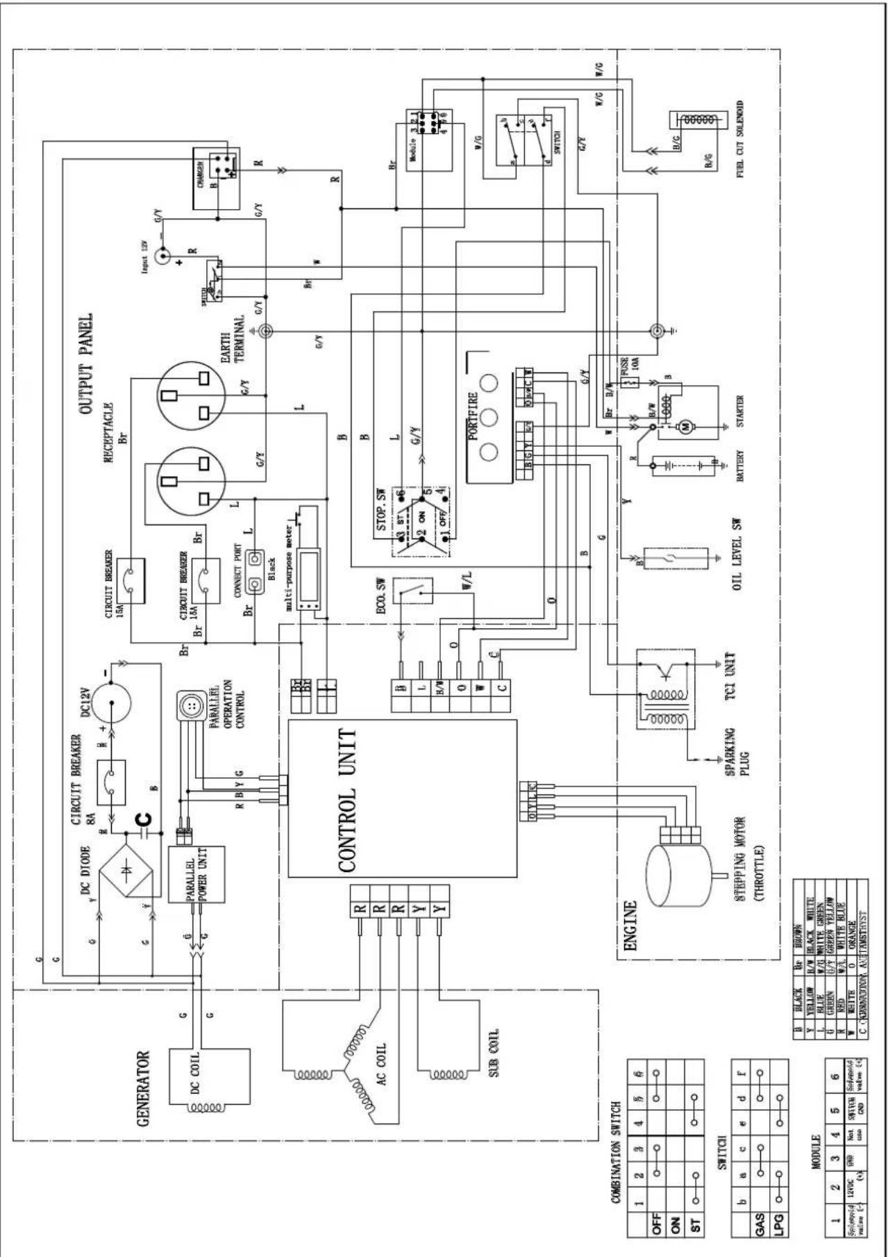
73001I-DF (EU/SC) WIRING DIAGRAM
flowchart
graph TD
    A["GENERATOR"] --> B["DC COIL"]
    B --> C["G"]
    C --> D["AC COIL"]
    D --> E["R"]
    E --> F["R"]
    F --> G["R"]
    G --> H["Y"]
    H --> I["Y"]
    I --> J["CONTROL UNIT"]
    J --> K["CONTROL POWER UNIT"]
    K --> L["CIRCUIT BREAKER 8A"]
    L --> M["DC12V"]
    M --> N["CIRCUIT BREAKER 15A"]
    N --> O["BR 13A"]
    O --> P["BR"]
    P --> Q["CONNECT PORT Black"]
    Q --> R["L multi-purpose meter"]
    R --> S["ECO.SW"]
    S --> T["STOP.SW"]
    T --> U["L OFF"]
    U --> V["PORTFIRE"]
    V --> W["B"]
    W --> X["B/WR"]
    X --> Y["SPARKING PLUG"]
    Y --> Z["TCI UNIT"]
    Z --> AA["STEPPING MOTOR (THROTTLE)"]
    AA --> AB["COMPANION ON"]
    AB --> AC["FUEL CUT SOLENDID"]

    subgraph OUTPUT PANEL
        AD["RECEPTACLE Br"] --> AE["BR 13A"]
        AE --> AF["BR"]
        AF --> AG["L"]
        AG --> AH["G/Y"]
        AH --> AI["L"]
        AI --> AJ["G/Y"]
        AJ --> AK["CHARGER R"]
        AK --> AL["R"]
        AL --> AM["Input 12V G/Y"]
        AM --> AN["G/Y"]
        AN --> AO["SHUTCH"]
        AO --> AP["G/Y"]
        AP --> AQ["R"]
        AQ --> AR["BR"]
        AR --> AS["W/G"]
        AS --> AT["SWITCH"]
        AT --> AU["G/Y"]
        AU --> AV["W/C"]
    end

    subgraph COMBINATION SWITCH
        AW["ON ST"] --> AX["OFF"] & AY
        AX --> AZ["SWITCH"] & BB
        BB --> BC["b a c e d f"]
        BC --> BD["GAS LPG"] & BE
        BE --> BF["B BLACK Br BROWN"]
        BF --> BG["Y YELLOW R/W BLACK WHITE"]
        BG --> BH["L BLUE W/U WHITE GREEN"]
        BH --> BI["G GREEN G/Y GREEN YELLOW"]
        BI --> BJ["N RED W/A WHITE BLUE"]
        BJ --> BK["W WHITE O ORANGE"]
        BK --> BL["C CHORDINION AUSTAMSTHYST"]
    end

    subgraph SWITCH
        BM["STEPPING MOTOR (THROTTLE)"] --> BN["SPARKING PLUG"]
        BN --> BO["TCI UNIT"]
        BO --> BP["OIL LEVEL SW"]
        BP --> BQ["B/BW STARTER"]
        BQ --> BR["PULSE 10A B"]
        BR --> BS["H/M M"]
        BS --> BT["B/WR B/W"]
        BT --> BU["SOSSH"]
        BU --> BV["PEESE 10A B"]
        BV --> BW["B/WR B/W"]
        BW --> BX["SOSSH"]
        BX --> BY["B/WR B/W"]
        BY --> BZ["PULSE 10A B/W"]
        BZ --> CA["B/WR B/W"]
        CA --> CB["PULSE 10A B/W"]
        CB --> CC["B/WR B/W"]
        CC --> CD["PULSE 10A B/W"]
        CD --> CE["B/WR B/W"]
        CE --> CF["PULSE 10A B/W"]
        CF --> CG["B/WR B/W"]
        CG --> CH["PULSE 10A B/W"]
        CH --> CI["B/WR B/W"]
        CI --> CJ["PULSE 10A B/W"]
        CJ --> CK["PULSE 10A B/W"]
        CK --> CL["PULSE 10A B/W"]
        CL --> CM["PULSE 10A B/W"]
        CM --> CN["PULSE 10A B/W"]
        CN --> CO["PULSE 10A B/W"]
        CO --> CP["PULSE 10A B/W"]
        CP --> CQ["PULSE 10A B/W"]
        CQ --> CR["PULSE 10A B/W"]
        CR --> CS["PULSE 10A B/W"]
        CS --> CT["PULSE 10A B/W"]
        CT --> CU["PULSE 10A B/W"]
        CU --> CV["PULSE 10A B/W"]
        CV --> CW["PULSE 10A B/W"]
        CW --> CX["PULSE 10A B/W"]
        CX --> CY["PULSE 10A B/W"]
        CY --> CZ["PULSE 10A B/W"]
        CZ --> DA["PULSE 10A B/W"]
        DA --> DB["PULSE 10A B/W"]
        DB --> DC["PULSE 10A B/W"]
        DC --> DD["PULSE 10A B/W"]
        DD --> DE["PULSE 10A B/W"]
        DE --> DF["PULSE 10A B/W"]
        DF --> DG["PULSE 10A B/W"]
        DG --> DH["PULSE 10A B/W"]
        DH --> DI["PULSE 10A B/W"]
        DI --> DJ["PULSE 10A B/W"]
        DJ --> DK["PULSE 10A B/W"]
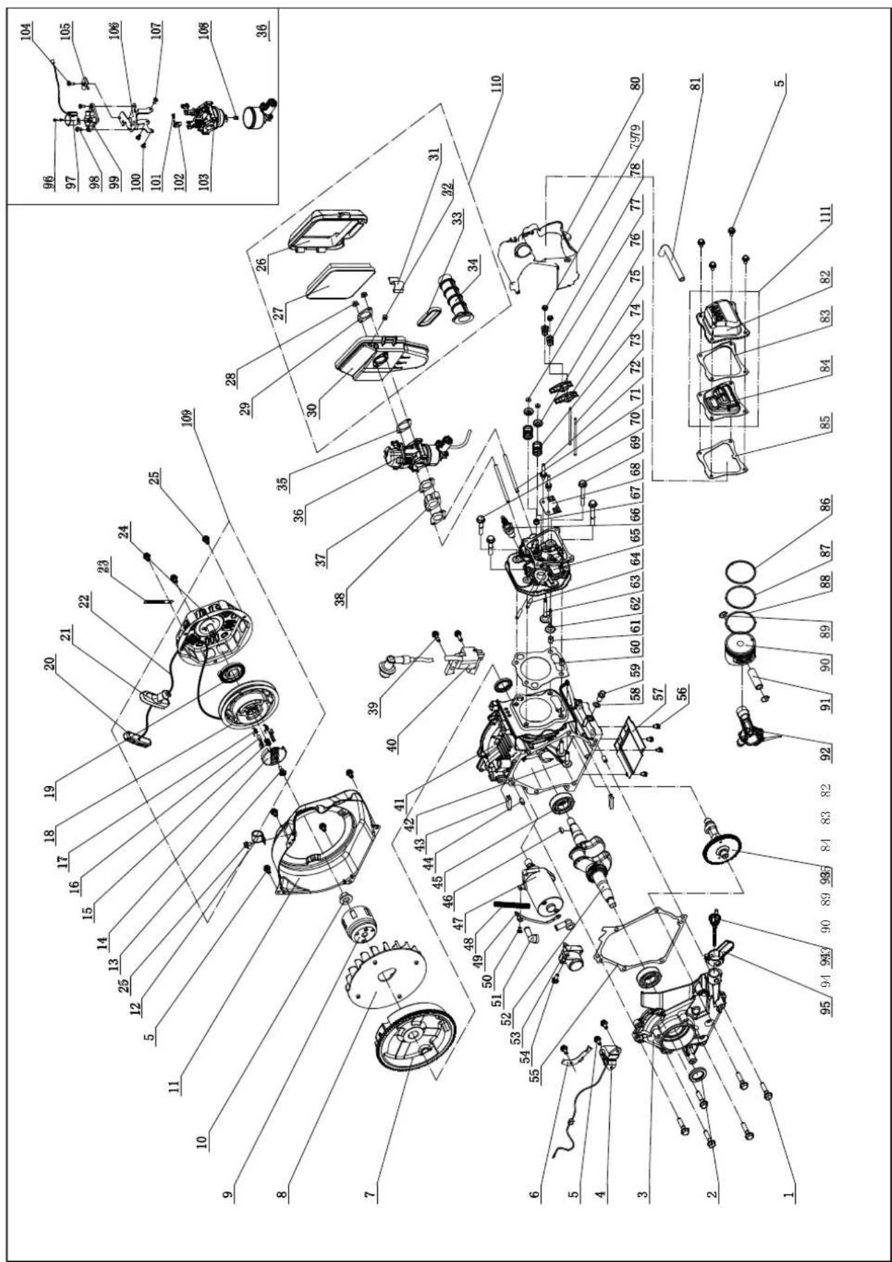
73001I-DF (EU/SC) PARTS DIAGRAM
text_image
Technical diagram of a mechanical assembly with numbered components and exploded view, likely for engineering or manufacturing purposes.73001I-DF (EU/SC) PARTS LIST
| No | Part Number | Description | QTY |
| 1 | 1.5789.0835 | Flange Bolt, M8 x 35 | 6 |
| 2 | 2.11.014 | Oil Seal | 2 |
| 3 | 83.030007.01 | Cover, Crankcase | 1 |
| 4 | 83.127000.01 | Oil Level Sensor | 1 |
| 5 | 1.5789.0612 | Flange Bolt, M6 x 12 | 11 |
| 6 | 83.030010.01 | Plate, Coil | 1 |
| 7 | 83.120100.02 | Flywheel | 1 |
| 8 | 83.080001.01 | Cooling Fan | 1 |
| 9 | 83.060001.01 | Pulley, Starter | 1 |
| 10 | 2.02.006 | Flange Nut, M14 x 1.5 | 1 |
| 11 | 87.080100.01.2 | Fan Cover | 1 |
| 12 | 2.06.029 | Clamp, ∅17 | 1 |
| 13 | 45.060008.00 | Screw, Ratchet Guide | 1 |
| 14 | 45.060007.00 | Ratchet Guide | 1 |
| 15 | 45.060009.00 | Spring, Ratchet Guide | 1 |
| 16 | 45.060002.00 | Starter Ratchet, Iron | 2 |
| 17 | 45.060003.00 | Spring, Ratchet | 2 |
| 18 | 21.061001.01 | Reel, Recoil Starter | 1 |
| 19 | 21.061005.00 | Spring, Recoil Starter | 1 |
| 20 | 81.061010.01 | Holder, Rope | 1 |
| 21 | 81.061006.00 | Grip, Rubber | 1 |
| 22 | 2.10.001 | Rope, ∅4 x 1570 | 1 |
| 23 | 2.05.050 | Clamp, 100 mm, Wire | 1 |
| 24 | 83.061100.01.2 | Cover, Recoil Starter | 1 |
| 25 | 1.5789.0608 | Flange Bolt, M6 x 8 | 4 |
| 26 | 83.091200.01 | Cover, Air Cleaner | 1 |
| 27 | 83.091300.01 | Element, Air Cleaner | 1 |
| 28 | 1.6177.1.06 | Lock Nut M6, Flange | 2 |
| 29 | 83.090001.01 | Flange, Steel | 1 |
| 30 | 83.091100.01 | Base, Air Cleaner | 1 |
| 31 | 83.091006.01 | Buckle | 1 |
| 32 | 83.091008.01 | Plug, Air Cleaner Base | 1 |
| 33 | 83.091002.02 | Seal | 1 |
| 34 | 83.090004.01 | Pipe, Air Cleaner | 1 |
| 35 | 83.130004.01 | Gasket, Air Cleaner | 1 |
| 36 | 87.130000.01 | Carburetor Assembly | 1 |
| 37 | 83.130002.01 | Gasket, Insulator | 2 |
| 38 | 83.130001.01 | Insulator, Carburetor | 1 |
| 39 | 1.5789.0620 | Flange Bolt, M6 x 20 | 2 |
| 40 | 28.123000.00 | Ignition Coil | 1 |
| 41 | 28.030100.01 | Crankcase | 1 |
| 42 | 83.040013.01 | Lifter, Valve | 2 |
| 43 | 83.030013.01 | Seal Strip, Crankcase Cover | 2 |
| 44 | 2.04.002 | Dawl Pin, 8 x 14 | 2 |
| 45 | 1.276.6205 | Bearing 6205 | 2 |
| 46 | 2.14.017 | Woodruff Key, 4 x 6.5 x 16 | 1 |
| 47 | 83.125100.01 | Starter Motor | 1 |
| 48 | 5.1320.010 | Plastic Corrugated Pipe, ∅6.8 x ∅10 x 100 | 1 |
| 49 | 5.1900.065 | Red Wire, 130 mm | 1 |
| 50 | 1.9074.3.0508 | Screw/Washer Assembly, M5 x 8 | 1 |
| 51 | 152.200013.01 | Sheath, Rubber | 2 |
| 52 | 83.050100.01 | Crankshaft | 1 |
| 53 | 83.125200.01 | Relay, Starter | 1 |
| 54 | 1.5789.0615 | Flange Bolt, M6 x 15 | 1 |
| 55 | 83.030008.01 | Gasket, Crankcase Cover | 1 |
| 56 | 1.9074.4.0510 | Screw/Washer Assembly, M5 x 10 | 4 |
The part numbers above are used for both UK and EU versions of the generator.
| No | Part Number | Description | QTY |
| 57 | 83.080014.01.01 | Air Guide Board | 1 |
| 58 | 2.03.016 | Washer, ∅10 x ∅16 x 1.5, Drain Bolt | 1 |
| 59 | 2.08.037 | Bolt, M10 x 1.25 x 25, Drain | 1 |
| 60 | 28.030009.00 | Gasket, Cylinder Head | 1 |
| 61 | 2.04.003 | Dowel Pin, ∅10 x 14 | 2 |
| 62 | 83.040006.01 | Valve, Exhaust | 1 |
| 63 | 83.040002.01 | Valve, Intake | 1 |
| 64 | 2.01.017 | Stud Bolt, M6 x 32 | 2 |
| 65 | 28.010100.00 | Cylinder Head | 1 |
| 66 | 2.15.008 | Spark Plug, F7RTC | 1 |
| 67 | 83.040017.01 | Oil Seal, Valve | 1 |
| 68 | 83.040004.01 | Guide Plate, Push Rod | 1 |
| 69 | 1.5789.0865 | Flange Bolt, M8 x 65 | 2 |
| 70 | 1.5789.0850 | Flange Bolt, M8 x 50 | 2 |
| 71 | 2.01.020 | Stud Bolt, M6 x 97 | 2 |
| 72 | 83.040010.01 | Bolt, Rocker Arm | 2 |
| 73 | 83.040005.01 | Push Rod | 2 |
| 74 | 83.040003.01 | Spring, Valve | 2 |
| 75 | 83.040009.01 | Rocker Arm, Valve | 2 |
| 76 | 83.040001.01 | Retainer, Valve Spring | 2 |
| 77 | 83.040014.01 | Valve Collet | 2 |
| 78 | 21.040020.00 | Adjusting Nut, Valve | 2 |
| 79 | 21.040021.00 | Nut, Lock | 2 |
| 80 | 83.080200.01 | Air Shroud, Cylinder | 1 |
| 81 | 23.020001.01 | Breather Tube | 1 |
| 82 | 83.021101.01 | Cover, Cylinder Head | 1 |
| 83 | 83.021001.01 | Gasket, Cylinder Head Element | 1 |
| 84 | 83.021200.01 | Element Component, Head Cover | 1 |
| 85 | 83.020002.01 | Gasket, Cylinder Head Cover | 1 |
| 86 | 28.050301.00 | Ring, First Piston | 1 |
| 87 | 28.050302.00 | Ring, Second Piston | 1 |
| 88 | 28.050303.00 | Ring, Oil | 1 |
| 89 | 2.09.002 | Circlip, ∅16 x ∅1 | 2 |
| 90 | 28.050005.00 | Piston | 1 |
| 91 | 83.050003.01 | Wrist Pin | 1 |
| 92 | 83.050200.01 | Connecting Rod Assembly | 1 |
| 93 | 83.040100.01 | Camshaft | 1 |
| 94 | 83.031000.01 | Oil Dipstick Assembly | 1 |
| 95 | 83.030035.01 | Oil Nipple | 1 |
| 96 | 1.818.0306.1 | Screw, M3 x 6, Black | 2 |
| 97 | 81.132200.00 | Stepper Motor | 1 |
| 98 | 1.9074.1.0408 | Screw/Washer Assembly, M4 x 8 | 2 |
| 99 | 82.132100.00 | Base, Stepper Motor | 1 |
| 100 | 1.819.0508 | Screw, M5 x 8 | 1 |
| 101 | 81.130010.00 | Spring, Connector | 1 |
| 102 | 81.130008.00 | Connector, Choke Valve Axis | 1 |
| 103 | 83.131000.05 | Carburetor | 1 |
| 104 | 1.9074.3.0512 | Screw/Washer Assembly, M5 x 12 | 1 |
| 105 | 81.130007.00 | Pressure Plate, Choke Control Line | 1 |
| 106 | 83.130005.03 | Support, Stepper Motor | 1 |
| 107 | 1.9074.3.0508 | Screw/Washer Assembly, M5 x 8 | 2 |
| 108 | 83.131017.01 | Main Jet, Standard | 1 |
| 83.131017.01.01 | Main Jet, Altitude | / | |
| 109 | 83.061000.01 | Recoil Assembly | 1 |
| 110 | 83.091000.01 | Air Cleaner Assembly | 1 |
| 111 | 83.021000.01 | Cylinder Head Cover Assembly | 1 |
Additional UK parts:
| PART DESCRIPTION | |
| 83.221000.00 | 240v 50hz Control unit |
| 5.1110.000 | 240v 13amp Receptacle |
73001I-DF (EU/SC) PARTS DIAGRAM
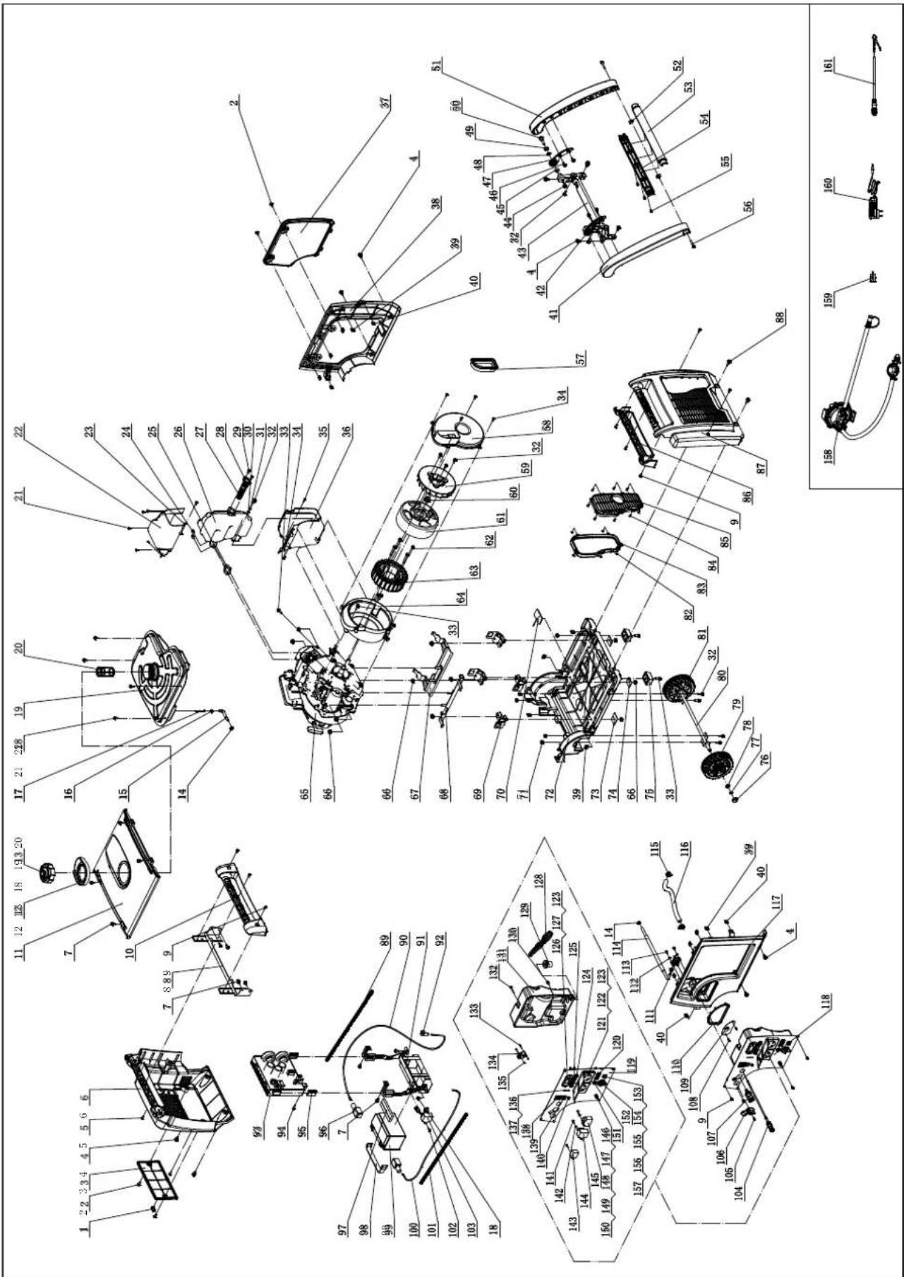
text_image
Technical diagram of a mechanical assembly with numbered components and exploded view, likely for assembly or manufacturing purposes.EN
73001I-DF (EU/SC) PARTS LIST
| No | Part Number | Description | QTY |
| 1 | 83.200205.02 | Hasp, Maintenance Cover | 1 |
| 2 | 2.08.055.1 | Bolt, Maintenance Cover, Black | 4 |
| 3 | 83.200204.02.2 | Maintenance Cover, Battery, Black | 1 |
| 4 | 2.08.052.1 | Bolt, M6 x 16 | 10 |
| 5 | 1.9074.4.0516.1 | Screw/Washer Assembly, M5 x 16, Black | 4 |
| 6 | 83.200201.02.2 | Cover, Left, Black | 1 |
| 7 | 1.5789.0612 | Flange Bolt, M6 x 12 | 11 |
| 8 | 83.201600.06 | Supporter, Left | 1 |
| 9 | 1.9074.4.0512.1 | Screw/Washer Assembly, M5 x 12, Black | 11 |
| 10 | 83.200701.02.2 | Handle, Left, Black | 1 |
| 11 | 83.200500.01.2 | Cover, Top, Black | 1 |
| 12 | 83.200502.01 | Spillway, Fuel Tank | 1 |
| 13 | 83.070100.02 | Cap, Fuel Tank | 1 |
| 14 | 2.06.016 | Clamp, ∅8.7 x b8 | 3 |
| 15 | 83.070011.01 | Fuel Pipe, Fuel Tank To Fuel Valve | 1 |
| 16 | 2.06.018 | Clamp, ∅10.5 x b8 | 1 |
| 17 | 111.070300.01 | Fuel Filter, Fuel Pipe | 1 |
| 18 | 2.08.068.2 | Flange Bolt, M5 x 13 | 6 |
| 19 | 83.071000.02 | Fuel Tank | 1 |
| 20 | 83.070300.01 | Fuel Filter, Fuel Tank | 1 |
| 21 | 1.845.4213 | Screw, ST4.2 x 13 | 6 |
| 22 | 83.081400.01 | Muffler Protector Assembly, Upper | 1 |
| 23 | 83.081004.01 | Plate | 1 |
| 24 | 2.02.001 | Nut M6, Long | 2 |
| 25 | 28.100001.00 | Gasket, Exhaust | 1 |
| 26 | 83.101100.01 | Muffler Assembly | 1 |
| 27 | 46.101300.08 | Spark Arrester Assembly | 1 |
| 28 | 46.101503.08 | Plate, Spark Arrester | 1 |
| 29 | 1.9074.4.0514 | Screw/Washer Assembly, M5 x 14 | 2 |
| 30 | 1.97.1.06 | Washer, ∅6 | 1 |
| 31 | 1.93.06 | Lock Washer, ∅6 | 4 |
| 32 | 1.5789.0615 | Flange Bolt, M6 x 15 | 10 |
| 33 | 1.5789.0620 | Flange Bolt, M6 x 20 | 6 |
| 43 | 1.845.4816 | Screw, ST4.8 x 16 | 6 |
| 35 | 1.845.4219 | Screw, ST4.2 x 19 | 1 |
| 36 | 83.081500.01 | Muffler Protector Assembly, Lower | 1 |
| 37 | 83.200402.01.2 | Protector, Rear Cover, Black | 1 |
| 38 | 83.200401.01.2 | Supporter, Rear Cover, Black | 1 |
| 39 | 2.02.014 | Nut M6, Square | 12 |
| 40 | 2.02.010 | Cage Nut, M5 | 8 |
| 41 | 83.200701.03.2 | Handle, Left, Black | 1 |
| 42 | 83.200704.01.2 | Bracket, Left, Black | 1 |
| 43 | 83.201600.05 | Supporter, Right | 1 |
| 44 | 1.6187.1.08 | Lock Nut M8, Flange | 2 |
| 54 | 2.13.001 | Bushing, ∅13.3 x ∅19.3 x 8 | 2 |
| 46 | 1.5789.0612.1 | Flange Bolt, M6 x 12, Black | 4 |
| 47 | 83.200704.02.2 | Bracket, Right, Black | 1 |
| 48 | 2.03.001 | Bushing, ∅13.3 x ∅19.3 x 2 | 2 |
| 49 | 2.03.002 | Washer, ∅13 x ∅20 x 2.5 | 2 |
| 50 | 2.08.002 | Bolt, M8 x 28 | 2 |
| 51 | 83.200701.04.2 | Handle, Right, Black | 1 |
| 52 | 2.02.002 | Nut M6, T-Style | 2 |
| 53 | 83.200705.01.2 | Handle, Upper, Black | 1 |
| 54 | 83.200705.02.2 | Handle, Lower, Black | 1 |
| 55 | 1.9074.3.0512.1 | Screw/Washer Assembly, M5 x 12, Black | 3 |
| 65 | 1.5789.0635.1 | Flange Bolt, M6 x 35, Black | 2 |
| 57 | 83.190006.01 | Rubber Sleeve, End Cover | 1 |
| 58 | 83.190003.01 | End Cover, Generator | 1 |
| 59 | 83.190001.01 | Fan, Generator | 1 |
| 60 | 2.02.006 | Flange Nut, M14 x 1.5 | 1 |
| 61 | 83.191100.01 | Rotor Assembly | 1 |
| 62 | 1.5789.0645 | Flange Bolt, M6 x 45 | 4 |
| 63 | 83.191200.15 | Stator Assembly | 1 |
| 64 | 83.190002.01 | End Cover, Mortor | 1 |
| 65 | 28.691 | Engine | 1 |
| 66 | 1.6177.1.08 | Lock Nut M8, Flange | 12 |
| 67 | 83.201600.02 | Supporter, Left | 1 |
| 86 38201600.01 | Supporter, Right | 1 | |
| 69 | 83.201200.01 | Motor Mount | 4 |
| 70 | 83.200607.01 | Plug, Oil Drain Hole | 1 |
| 71 | 1.6182.06 | Lock Nut M6 | 6 |
| 72 | 83.200601.01 | Base Setting Component | 1 |
| 73 | 83.200609.02 | Steel Plate 2 | 2 |
| 74 | 83.200609.01 | Steel Plate 1 | 2 |
| 75 | 83.201400.01 | Rubber Pad | 2 |
| 76 | 83.201702.01 | Plug, Wheel | 2 |
| 77 | 1.894.1.12 | Retaining Ring, ∅12 | 2 |
| 78 | 1.848.12 | Washer, ∅12 | 2 |
| 79 | 83.201701.02 | 5.5 in. Wheel, Right | 1 |
| 80 | 83.201500.01 | Axle | 1 |
| No | Part Number | Description | QTY |
| 81 | 83.201701.01 | 5.5 in. Wheel, Left | 1 |
| 82 | 83.200305.01 | Spring Patch | 5 |
| 83 | 83.200304.01 | Rubber Seal, Muffler Cover | 1 |
| 84 | 1.845.3595 | Screw, ST3.5 x 9.5 | 8 |
| 85 | 83.200303.01.2 | Muffler Cover, Black | 1 |
| 86 | 83.200701.01.2 | Handle, Right, Black | 1 |
| 87 | 83.200302.01.2 | Cover, Right Side, Black | 1 |
| 88 | 2.08.075.1 | Bolt, M6 x 20, Black | 2 |
| 89 | 5.1320.023 | Plastic Corrugated Pipe, ∅6.8 x ∅10 x 530 | 1 |
| 90 | 5.1900.019 | Red Wire, Battery, 600 mm | 1 |
| 91 | 83.200018.01 | Holder, Control Unit and Battery | 1 |
| 92 | 152.200013.01 | Sheath, Rubber | 1 |
| 93 | 83.221000.94 | Control Unit, 3.1KW, 240V/50Hz, Parallel | 1 |
| 94 | 1.16674.0516 | Flange Bolt, M5 x 16 | 1 |
| 95 | 81.220001.00 | Protector, Control Unit | 2 |
| 96 | 122.200013.01 | Sheath, Rubber | 2 |
| 97 | 83.200908.01 | Fixation Bar, Sponge | 1 |
| 98 | 122.200904.00 | Pinch, Rubber | 1 |
| 99 | 9.1000.070 | Battery, 149.5 x 85 x 94, 7AH | 1 |
| 100 | 5.1900.060 | Black Wire, Battery, 600 mm | 1 |
| 101 | 5.1320.022 | Plastic Corrugated Pipe, ∅6.8 x ∅10 x 450 | 1 |
| 102 | 1.16674.0512 | Flange Bolt, M5 x 12 | 1 |
| 103 | 5.1800.003 | Rectifier | 1 |
| 104 | 83.130200.01 | Pull Choke Assembly | 1 |
| 105 | 1.823.0410 | Screw, M4 x 10 | 1 |
| 106 | 87.070001.01 | Knob, Fuel Valve | 1 |
| 107 | 87.070021.01 | Quick Coupler | 1 |
| 108 | 1.823.0408 | Screw, M4 x 8 | 2 |
| 109 | 83.061200.01.2 | Guide Plate, Rope, Black | 1 |
| 110 | 83.200106.01 | Protector, Front Cover | 1 |
| 111 | 83.070400.01 | Fuel Valve | 1 |
| 112 | 1.97.1.05 | Washer, ∅5 | 2 |
| 113 | 1.845.4819 | Screw, ST4.8 x 19 | 2 |
| 114 | 83.070011.02 | Fuel Pipe, Fuel Valve To Carburetor | 1 |
| 115 | 2.06.023 | Clip, ∅20 | 2 |
| 116 | 87.070012.01 | Pipe, 280mm | 1 |
| 117 | 87.200101.01.2 | Front Cover, Dual Fuel, Black | 1 |
| 118 | 73001i-DF.21 | Control Panel Assembly | 1 |
| 119 | 83.019.44.45 | Control Panel, Yellow | 1 |
| 120 | 83.210001.00.1 | Connect Port, 125V/25A, Black | 2 |
| 121 | 5.1120.011 | Receptacle | 1 |
| 122 | 1.819.0414 | Screw M4 x 14 | 8 |
| 123 | 1.6177.1.04.1 | Lock Nut M4, Flange, Black | 10 |
| 124 | 5.1200.215 | A.C 15A Breaker, Push Button | 2 |
| 125 | 5.1000.000.3 | Switch, Battery, Red | 1 |
| 126 | 5.1430.002 | Intelligauge | 1 |
| 127 | 1.9074.4.0414.1 | Screw M4 x 14, Black | 2 |
| 128 | 73001i-DF.21.10 | Wire Assembly | 1 |
| 129 | 122.210003.01 | Grommet | 1 |
| 130 | 1.9074.4.0512 | Screw/Washer Assembly, M5 x 12 | 1 |
| 131 | 87.210002.01 | Control Box | 1 |
| 132 | 1.9074.1.0535 | Screw/Washer Assembly, M5 x 35 | 1 |
| 133 | 1.823.0325 | Screw, M3 x 25 | 2 |
| 134 | 5.1050.000 | Switch | 1 |
| 135 | 1.6170.03 | Nut M3 | 2 |
| 136 | 83.210016.00 | Speed Limiter | 1 |
| 137 | 1.818.0514.3 | Screw, M5 x 14, Green | 2 |
| 138 | 5.1000.001 | Ignition Switch, Red | 1 |
| 139 | 5.1010.003.1 | Switch, Economy, Black | 1 |
| 140 | 5.1110.006 | Receptacle, Battery Charger | 1 |
| 141 | 1.845.3516 | Screw, ST3.5 x 16 | 3 |
| 142 | 1.97.1.04 | Washer, ∅4 | 2 |
| 143 | 5.1840.002 | Case, Power Supply | 1 |
| 144 | 5.1820.001 | Charger | 1 |
| 145 | 5.1800.004 | Rectifier | 1 |
| 146 | 1.5783.0520.3 | Bolt, M5 x 20, Green | 1 |
| 147 | 1.862.05 | Lock Washer, ∅5, Toothed | 1 |
| 148 | 1.6170.05.3 | Nut M5, Green | 2 |
| 149 | 1.93.05.3 | Lock Washer, ∅5, Green | 2 |
| 150 | 1.97.1.05.3 | Washer, ∅5, Green | 2 |
| 151 | 5.1200.308 | 8Amp Circuit Breaker, Push Button | 1 |
| 152 | 5.1110.005 | Receptacle, DC.12V | 1 |
| 153 | 5.1910.001 | Special Receptacle | 1 |
| 154 | 1.818.0210.3 | Screw M2 x 10, Green | 4 |
| 155 | 1.93.02.3 | Spring Washer ∅2, Green | 4 |
| 156 | 1.97.1.02.3 | Washer ∅2, Green | 4 |
| 157 | 1.6170.02.3 | Nut M2, Green | 4 |
| 158 | 87.130000.93 | LPG Hose With Regulator | 1 |
| 159 | 9.1700.003 | Plug, USB 5V/2.1A | 1 |
| 160 | 9.1700.006 | Smart Charger, 12V | 1 |
| 161 | 9.1600.012 | Cables, 12V, 2m | 1 |
Test Verification of Conformity
Verification Number: 220500634HZH-V1
On the basis of the referenced test report(s), sample(s) tested of the below product have been found to comply with the standards harmonized with the directives listed on this verification at the time the tests were carried out. Other standards and Directives may be relevant to the product. This verification is part of the full test report(s) and should be read in conjunction with it. This verification replaces previous verification 190800418HZH-V1 dated on 2019-09-05.
Once compliance with all product relevant CC mark directives are verified, including any relevant e.g. risk assessment and production control, the manufacturer may indicate compliance by signing a Declaration of Conformity themselves and applying the mark to products identical to the tested sample(s).
| Applicant Name & Address: | CHAMPION POWER EQUIPMENT, INC.12039 SMITH AVENUE, SANTA FE SPRINGS, CA 90670, USA |
| Product Description: | Low power generating sets |
| Ratings & Principle Characteristics: | 50Hz, CosΦ=1,0, DC 12V, 8A, others see next page |
| Models/Type References: | See next page |
| Brand Name: | CHAMPION, CHAMPION POWER EQUIPMENT, CHAMPION GLOBAL POWER EQUIPMENT |
| Relevant Standards/Directives: | EN ISO 8528-13:2016The Machinery Directive 2006/42/EC |
| Verification Issuing Office Name & Address: | Intertek Testing Services Zhejiang Ltd., Hangzhou Branch4th Floor, Building 4#, No. 22, 22nd Street, Qiantang District Hangzhou, China 310018 |
| Date of Tests: | 2022-11-03 |
| Test Report Number(s): | 180600467HZH-001+A2 |

Signature
Name: Jun Wu
Position: Manager
Date: 07 Nov.2022
This Verification is for the exclusive use of Intertek's client and is provided pursuant to the agreement between Intertek and its Client. Intertek's responsibility and liability are limited to the terms and conditions of the agreement. Intertek assumes no liability to any party, other than to the Client in accordance with the agreement, for any loss, expense or damage occasioned by the use of this Verification. Only the Client is authorized to permit copying or distribution of this Verification. Any use of the Intertek name or one of its marks for the sale or advertisement of the tested material, product or service must first be approved in writing by Intertek. The observations and test/inspection results referenced in this Verification are relevant only to the sample tested/inspected. This Verification by itself does not imply that the material, product, or service is or has ever been under an Intertek certification program.
APPENDIX: Test Verification of Conformity
This is an Appendix to Test Verification of Conformity Number: 220500634HZH-V1.
Models/Type References
| Model Rated | voltage | Rated power Max. | power | Parallel output power |
| 82001i-EU, 82001i-SC, 82001i-DE | 220V 1,6kW | W 1,75kW 3,0kW | ||
| 82001i 230V | ||||
| 82001i-DF-EU, 82001i-DF-SC, 82001i-DF-DE | 220V 1,6kW | W(Gasoline)/1,44kW(LPG) | 3,0kW(Gasoline)/2,75kW(LPG) | |
| 82001i-DF 230V | ||||
| 73001i-EU, 73001i-SC, 73001i-DE, | 220V 3,2kW | W 3,4kW 6,0kW | ||
| 73001i-P-EU, 73001i-P-SC, 73001i-P-DE | ||||
| 73001i 230V | ||||
| 73001i-P | ||||
| 73001i-DF-EU, 73001i-DF-SC, 73001i-DF-DE | 220V 3,2kW | W(Gasoline)/2,88kW(LPG) | 6,0kW(Gasoline)/5,45kW(LPG) | |
| 73001i-DF 230V | ||||
| CPG4000DHY-EU, CPG4000DHY-SC, CPG4000DHY-DE, | 220V 3,5kW | W 3,6kW 6,6kW | ||
| CPG4000DHY 230V | ||||
| CPG4000DHY-DF-EU, CPG4000DHY-DF-SC, CPG4000DHY-DF-DE | 220V 3,5kW | W(Gasoline)/3,15kW(LPG) | 6,6kW(Gasoline)/5,95kW(LPG) | |
| CPG4000DHY-DF 230V |
Signature
Name: Jun Wu
Position: Manager
Date: 7 November 2022
This Verification is for the exclusive use of Intertek's client and is provided pursuant to the agreement between Intertek and its Client. Intertek's responsibility and liability are limited to the terms and conditions of the agreement. Intertek assumes no liability to any party, other than to the Client in accordance with the agreement, for any loss, expense or damage occasioned by the use of this Verification. Only the Client is authorized to permit copying or distribution of this Verification. Any use of the Intertek name or one of its marks for the sale or advertisement of the tested material, product or service must first be approved in writing by Intertek. The observations and test/inspection results referenced in this Verification are relevant only to the sample tested/inspected. This Verification by itself does not imply that the material, product, or service is or has ever been under an Intertek certification program.
Intertek
GFT-OP-11b (02-April-2020)
Test Verification of Conformity
Verification Number: 220500636HZH-V1
On the basis of the referenced test report(s), sample(s) tested of the below product have been found to comply with the standards harmonized with the regulation(s) listed on this verification at the time the tests were carried out. Other standards and Regulations may be relevant to the product. This verification is part of the full test report(s) and should be read in conjunction with it. This verification replaces previous verification 210300686HZH-V1 dated on 2021-04-13.

Once compliance with all product relevant CA mark regulations are verified, including any relevant e.g. risk assessment and production control, the manufacturer may indicate compliance by signing a Declaration of Conformity themselves and applying the mark to products identical to the tested sample(s).
| Applicant Name & Address: | CHAMPION POWER EQUIPMENT, INC.12039 SMITH AVENUE, SANTA FE SPRINGS, CA 90670, USA |
| Product Description: | Low power generating sets |
| Ratings & Principle Characteristics: | 240V~, 50Hz, CosΦ=1,0, DC 12V, 8A, others see next page |
| Models/Type References: | 82001i-UK, 82001i-DF-UK, 73001i-UK, 73001i-P-UK, 73001i-DF-UK, CPG4000DHY-UK, CPG4000DHY-DF-UK |
| Brand Name: | CHAMPION, CHAMPION POWER EQUIPMENT, CHAMPION GLOBAL POWER EQUIPMENT |
| Relevant Standards/Regulations: | EN ISO 8528-13:2016Supply of Machinery (Safety) Regulations 2008 |
| Verification Issuing Office Name & Address: | Intertek Testing Services Zhejiang Ltd., Hangzhou Branch4th Floor, Building 4#, No. 22, 22nd Street, Qiantang District Hangzhou, China 310018 |
| Date of Tests: | 2022-11-08 |
| Test Report Number(s): | 210300686HZH-001+A1 |

Signature
Name: Jun Wu
Position: Manager
Date: 11 Nov.2022
This Verification is for the exclusive use of Intertek's client and is provided pursuant to the agreement between Intertek and its Client. Intertek's responsibility and liability are limited to the terms and conditions of the agreement. Intertek assumes no liability to any party, other than to the Client in accordance with the agreement, for any loss, expense or damage occasioned by the use of this Verification. Only the Client is authorized to permit copying or distribution of this Verification. Any use of the Intertek name or one of its marks for the sale or advertisement of the tested material, product or service must first be approved in writing by Intertek. The observations and test/inspection results referenced in this Verification are relevant only to the sample tested/inspected. This Verification by itself does not imply that the material, product, or service is or has ever been under an Intertek certification program.
Intertek
Page 1 of 2
GFT-OP-11c (01-January-2021)

text_image
CHAMPION GLOBAL POWER EQUIPMENTFor warranty and repair enquiries, please contact the retailer where you purchased your Champion product.
Champion Power Equipment Europe Service & Technical Contacts
United Kingdom:
BPE Holdings
Unit 17-18
Bradley Hall Trading Estate
Bradley Lane, Standish
Wigan, WN6 0XQ, UK
service@bpeholdings.co.uk