GR6 - Indoor bike trainer Horizon Fitness - Free user manual and instructions
Find the device manual for free GR6 Horizon Fitness in PDF.
| Product Type | Indoor Bike Trainer (Exercise Bike) |
| Brand | Horizon Fitness |
| Model | GR6 |
| Use | Indoor training, stationary cycling |
| Resistance | Manual incremental adjustment via tension control knob |
| Emergency brake | Red lever to immediately stop the flywheel |
| Flywheel | Fixed flywheel with belt drive |
| Seat adjustment - height | Adjustment lever to adjust height (do not exceed the marks) |
| Seat adjustment - horizontal position | Lever to slide the seat forward or backward |
| Handlebar adjustment - height | Adjustment lever to raise/lower the handlebar (do not exceed the marks) |
| Pedals - straps | Adjustable straps to keep the foot in the toe cage |
| Pedals - threading | Left pedal (L) left-hand thread, right pedal (R) right-hand thread |
| Stabilizers | Front and rear, with leveling feet |
| Transport | Transport wheels integrated into the front stabilizer |
| Required safety distance | 60 cm around the device, 50 cm minimum from other equipment |
| Daily maintenance | Wipe after use with mild soap and water, dry |
| Weekly maintenance | Check flywheel alignment, chain tension, tightening of parts |
| Monthly maintenance | Inspect for rust, wear of brake pads, seat, pedals; grease seat post and handlebar |
| Main parts (assembly) | Frame, front/rear stabilizers, handlebar, handlebar post, seat post, seat, pedals, cranks |
| Serial number | On the front stabilizer tube of the bike |
| Technical support | Contact the local dealer or customer service (coordinates on the information card) |
Frequently Asked Questions - GR6 Horizon Fitness
User questions about GR6 Horizon Fitness
0 question about this device. Answer the ones you know or ask your own.
Ask a new question about this device
Download the instructions for your Indoor bike trainer in PDF format for free! Find your manual GR6 - Horizon Fitness and take your electronic device back in hand. On this page are published all the documents necessary for the use of your device. GR6 by Horizon Fitness.
USER MANUAL GR6 Horizon Fitness
natural_image
Silhouette of a person exercising on an outdoor bike (no text or symbols visible)

natural_image
Silhouette of a person exercising on an outdoor bike (no text or symbols visible)GR3 GR5 GR6
OWNER'S MANUAL
BEDIENUNGSANLEITUNG
GEBRUIKERSHANDLEIDING
MANUEL D'UTILISATION
3 ENGLISH
35 DEUTSCH
67 NEDERLANDS
99 FRANÇAIS
H218_BF3-4 CM r1_A_A ind 2-3 A267B 5:13 A9
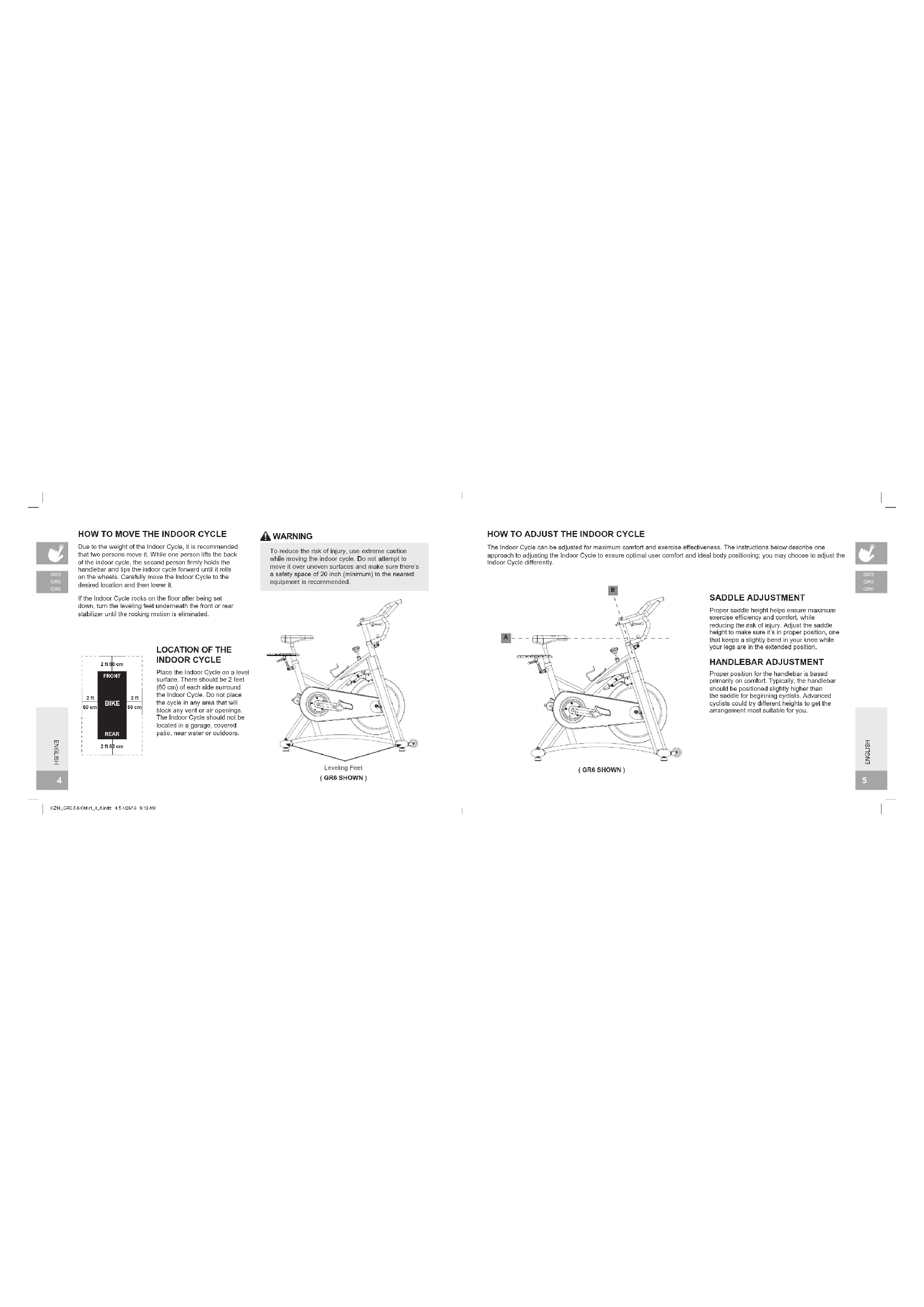
Due to the weight of the Indoor Cycle, it is recommended that two persons move it. While one person lifts the back of the Indoor cycle, the second person firmly holds the handlebar and tips the indoor cycle forward until it rolls on the wheels. Carefully move the Indoor Cycle to the desired location and then lower it.
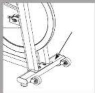
If the Indoor Cycle rocks on the floor after being set down, turn the leveling feet underneath the front or rear stabilizer until the rocking motion is eliminated.


LOCATION OF THE INDOOR CYCLE
Place the Indoor Cycle on a level surface. There should be 2 feet (60 cm) of each side surround the Indoor Cycle. Do not place the cycle in any area that will block any vent or air openings. The Indoor Cycle should not be located in a garage, covered patio, near water or outdoors.
[Non-Text]
WARNING
To reduce the risk of injury, use extreme caution while moving the indoor cycle. Do not attempt to move it over uneven surfaces and make sure there's a safety space of 20 inch (minimum) to the nearest equipment is recommended.
natural_image
Line drawing of a stationary exercise bike with rotating wheel and support frame (no text or symbols)Leveling Feet (GR6 SHOWN)
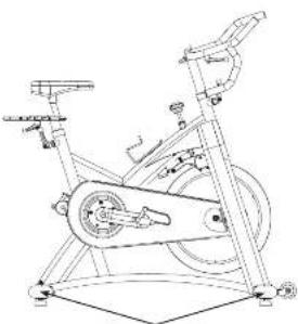
HOW TO ADJUST THE INDOOR CYCLE
The Indoor Cycle can be adjusted for maximum comfort and exercise effectiveness. The instructions below describe one approach to adjusting the Indoor Cycle to ensure optimal user comfort and ideal body positioning; you may choose to adjust the Indoor Cycle differently.

text_image
Technical diagram of a stationary exercise bike with labeled components A and B(GR6 SHOWN)
SADDLE ADJUSTMENT
Proper saddle height helps ensure maximum exercise efficiency and comfort, while reducing the risk of injury. Adjust the saddle height to make sure it's in proper position, one that keeps a slightly bend in your knee while your legs are in the extended position.
HANDLEBAR ADJUSTMENT
Proper position for the handlebar is based primarily on comfort. Typically, the handlebar should be positioned slightly higher than the saddle for beginning cyclists. Advanced cyclists could try different heights to get the arrangement most suitable for you.
H215_070-4-CMrl_4_Aml: 4d A2678 2x13 AM


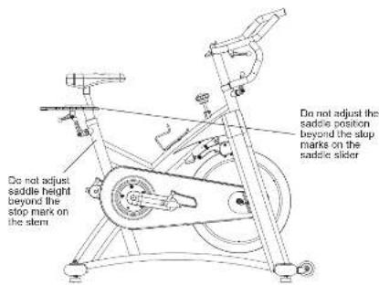
text_image
Do not adjust the saddle position beyond the stop marks on the saddle slider Do not adjust the saddle height beyond the stop mark on the stemTO ADJUST THE SADDLE HEIGHT:
Rotate the adjustment lever counterclockwise and adjust the saddle to a comfortable pedaling position. Rotate the lever clockwise to lock saddle position.
TO ADJUST THE SADDLE HORIZONTAL POSITION:
Rotate the adjustment lever counterclockwise to slide the saddle forward or backward as desired. Rotate the lever clockwise to lock saddle position. Test the saddle slide for proper operation.
ENGLISH
6
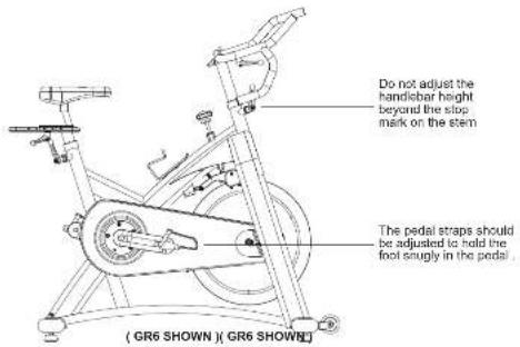
text_image
Do not adjust the handisbar height beyond the slip mark on the stem The pedal straps should be adjusted to hold the foot snugly in the pedal. ( GR6 SHOWN ) ( GR6 SHOWN )TO ADJUST THE HANDLEBAR HEIGHT:
Rotate the adjustment lever counterclockwise to adjust the handlebar height. Raise or lower the handlebar to the desired height. Rotate the lever clockwise to lock handlebar position.
TO ADJUST THE PEDAL STRAPS:
Place each foot ankle on the pedal and in the toe clip that the foot ankle is centered over the pedal spindle (center of the pedal). Rotate one foot to arms reach and pull up on the toe clip strap. Repeat for the other foot. Keep your knees over your feet as you pedal. To remove your foot from the toe clip, loosen the strap and pull out.
H215_070-4-CMrl_4_Aml: 6-7-A267B 2x13 AM

ENGLISH
7

TENSION CONTROL AND EMERGENCY BRAKE
The preferred level of difficulty in pedaling (resistance) can be regulated in fine increments by use of the tension control knob. To increase the resistance, turn the tension control knob clockwise. To decrease the resistance, turn the knob counter clockwise.
IMPORTANT:
- To stop the flywheel while pedaling, push down on the red emergency brake lever.
- The flywheel should quickly come to a complete stop.
- Make sure your shoes are fixed into the toe clip.
- Apply full resistance load when the bike is not in use to prevent injuries due to moving drive gear components.
WARNING
The Indoor Cycle does not have a free moving flywheel; the pedals will continue to move together with the flywheel until the flywheel stops. Reducing speed in a controlled manner is required. To stop the flywheel immediately, push down the red emergency broke lever. Always pedal in a controlled manner and adjust your desired cadence according to your own abilities. Push the red lever down = emergency stop.

text_image
Tension control knob Emergency brake (GR6 SHOWN)WARNING
The Indoor Cycle was a fixed flywheel that builds momentum and will keep the pedals turning even after the user stops pedaling or if the user's feet slip off. DO NOT ATTEMPT TO REMOVE YOUR FEET FROM THE PEDALS OR DISMOUNT THE MACHINE UNTIL BOTH THE PEDALS AND THE FLYWHEEL HAVE COMPLETELY STOPPED. Failure to follow these instructions may lead to loss of control and the potential for serious injury.
F215_070-4 CMr1_4_Aml 8/0-42676 2x13 AM
ASSEMBLY
WARNING
There are several areas during the assembly process that special attention must be paid. It is very important to follow the assembly instructions correctly and to make sure all parts are firmly tightened. If the assembly instructions are not followed correctly, the indoor cycle could have parts that are not tightened and will seem loose and may cause irritating noises. To prevent damage to the indoor cycle, the assembly instructions must be reviewed and corrective actions should be taken.
Before proceeding, find your indoor cycle a serial number located on the front stabilizer of the cycle and enter it in the space provided below.
ENTER YOUR SERIAL NUMBER IN THE BOX BELOW

- Refer to the SERIAL NUMBER and MODEL NAME when calling for service. - Be sure to enter both the SERIAL NUMBER and MODEL NAME on your warranty card.


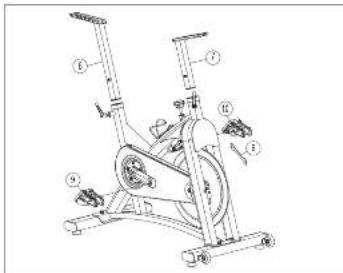
MODEL INFORMATION
text_image
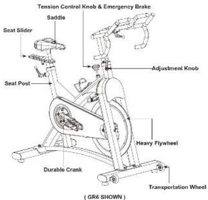
Tension Control Knob & Emergency Brake Saddle Seat Slider Seat Post Adjustment Knob Heavy Flywheel Durable Crank Transportation Wheel ( GR6 SHOWN )ENGLISH
H218_070-4-CMnI_A_Aml 10-1142518 9.13 AM
MAIN PARTS INCLUDED:
□ 1 Main Frame
Front & rear stabilizer
□ Handicbar Set
□ Handlebar Mast Set (Only GR6)
□ Seat Post Set
□ Pedal Set
PARTS PACKING
INCLUDED:
□ 1 Paris box
□ 1 Owner's Manual
PRE ASSEMBLY
UNPACKING
Due to the weight of the indoor cycle, it is recommended that two persons perform the assembly. Set the indoor cycle in a cleared area and remove all packing materials: do not dispose of the packing materials until assembly is completed.
NOTE: During each assembly step, ensure that ALL nuts and bolts are in place and partially threaded in before completely tightening any ONE bolt.
NOTE: A light application of grease may aid in the installation of hardware. Any grease, such as lithium bike grease is recommended.
NEED HELP?
If you have questions or if there are any missing parts, contact your local dealer. Contact information may be located on the back panel of this manual or on warranty card.

ENGLISH
1110

GR3 ASSEMBLY STEP 1
| HARDWARE FOR STEP 1: | ||
| NO. | DESCRIPTION QTY | |
| 1 | HANDLE BAR 1 | |
| 2 | SEAT POST 1 | |
| 3 | LEFT PEDAL 1 | |
| 4 | RIGHT PEDAL 1 | |
| 5 | COMBINATION WRENCH | 1 |
text_image
Technical diagram of a stationary exercise machine with numbered components and labeled partsA. Install the HANDLEBAR (1) into the frame receptor and secure with the knob.
B. Install the SEAT POST (2) into the frame receptor and secure with the knob.
C Thread the LEFT PEDAL (3) that has "L" on the spindle to the left side arm of the cycle using the COMBINATION WRENCH (5). Please note that the L pedal is left-hand threaded which needs to be turned counter clockwise to tighten.
D Thread the RIGHT PEDAL (4) that has "R" on the spindle to the right side arm of the cycle using the COMBINATION WRENCH (5). Please note that the R pedal is right-hand threaded which needs to be turned clockwise to lighten.
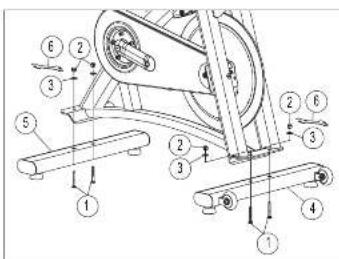
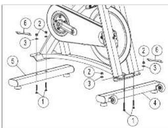
GR3 ASSEMBLY STEP 2
| HARDWARE FOR STEP 2 : | ||
| NO. | DESCRIPTION QTY | |
| 6 | ALLEN WREWCH | 1 |
| 7 | ALLEN BOLTS (WB X 16L) | 8 |
| 8 | WASHERS | 9 |
| 9 | FRONT STABILIZER | 1 |
| 10 | NEAR STABILIZER | 1 |
A Attach the FRONT STABILIZER (9) to the frame using 2 ALLEN BOLTS (7) and 2 WASHERS (8), and secure firmly by ALLEN WRENCH (6).
B. Attach the REAR STABILIZER (10) to the frame using 2 ALLEN BOLTS (7) and 2 WASHERS (8), and secure firmly by ALLEN WRENCH (6).

text_image
Technical diagram of a mechanical assembly with numbered components for identification

F218_043-5-5 CMrl_4_A Ind: 12-13
42818 9:13 AM
GR5 ASSEMBLY STEP 1

| HARDWARE FOR STEP 1 : | ||
| NO. | DESCRIPTION QTY | |
| 1 | REAR STABILIZER 1 | |
| 2 | BOLTS 4 | |
| 3 | NUTS | 4 |
| 4 | WASHERS | 4 |
| 5 | WHENCH | 1 |
| 6 | FRONT STABILIZER | 1 |
text_image
Technical diagram of an exercise machine with numbered components for identificationA Attach the REAR STABILIZER (1) to the frame using 2 NUTS (3), 2 WASHERS (4) and 2 BOLTS (2), and secure firmly using the adjustable WRENCH (5).
B Attach the FRONT STABILIZER (6) to the frame using 2 NUTS (3). 2 WASHERS (4) and 2 BOLTS (2), and secure firmly using the adjustable WRENCH (5).
GR5 ASSEMBLY STEP 2
| HARDWARE FOR STEP 2 : | ||
| NO. | DESCRIPTION QTY | |
| 5 | WIRECH | 1 |
| 7 | RIGHT PEDAL | 1 |
| 8 | LEFT PEDAL | 1 |
| 9 | HANDLERAR | 1 |

text_image
Technical diagram of an exercise bike with labeled components and motion indicatorsA Thread the LEFT PEDAL (8) that has "L" on the spindle to the left side arm of the cycle using the adjustable WRENCH (5). Please note that the L pedal is left-hand threaded which needs to be turned counter clockwise to tighten.
B Thread the RIGHT PEDAL (7) that has "R" on the spindle to the right side arm of the cycle using the adjustable WRENCH (5). Please note that the R pedal is right-hand threaded which needs to be turned clockwise to tighten.
C Install the HANDLEBAR (9) into the frame receptor and secure with the quick release.


F25_D13-4 CMr1_4_Ainds 14-15
42M18 913 AM

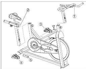
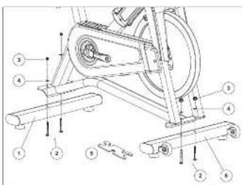
GR6 ASSEMBLY STEP 1
| HARDWARE FOR STEP 1 : | ||
| NO. | DESCRIPTION QTY | |
| 1 | BOLTS4 | |
| 2 | NUTS 4 | |
| 3 | WASHERS (MB) 4 | |
| 4 | FRONT STABILIZER 1 | |
| 5 | REAR STABILIZER | 1 |
| 6 | WRENCH | 1 |
text_image
Technical diagram of a mechanical assembly with numbered components and directional arrows indicating motion or assembly.A Attach the FRONT STABILIZER (4) and REAR STABILIZER (5) to the frame using 4 BOLTS (1) and 4 WASHERS (3) and 4 NUTS (2), and secure firmly by WRENCH (6).
GR6 ASSEMBLY STEP 2
| HARDWARE FOR STEP 2 : | ||
| NO. | DESCRIPTION QTY | |
| 6 | WRENCH | 1 |
| 7 | HANDLEBAR MAST | 1 |
| 8 | SEAT POST | 1 |
| 9 | RIGHT PEDAL | 1 |
| 10 | LEFT PEDAL | 1 |
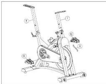
text_image
Technical diagram of an exercise bike with numbered components for identificationA Thread the LEFT PEDAL (10) that has 'L' on the spindle to the left side arm of the cycle using the WRENCH (6). Please note that the L pedal is left-hand threaded which needs to be turned counter clockwise to tighten.
B Thread the RIGHT PEDAL (9) that has "R" on the spindle to the right side arm of the cycle using the WRENCH (6). Please note that the R pedal is right hand threaded which needs to be turned clockwise to tighten.
C Install the HANDLEBAR MAST(7) into the frame receptor and secure with the quick release.
D Install the SEAT POST(8) into the frame receptor and secure with the quick release.


F25_D13-4 CMr1_4_Ainds 18-7
42018 913 AM

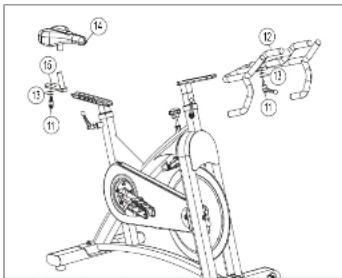
GR6 ASSEMBLY STEP 3
| HARDWARE FOR STEP 3 : | ||
| NO. | DESCRIPTION QTY | |
| 11 | QUICK RELEASE 2 | |
| 12 | HANDLEBAR 1 | |
| 13 | WASHERS (M10) 4 | |
| 14 | SADDLE 1 | |
| 15 | SEAT SLIDER 1 | |
text_image
Technical diagram of an exercise bike with numbered components for identification and assembly reference.A Install the HANDLEBAR (12) into the handlebar mast receptor using 2 WASHERS (13) and secure with the QUICK RELEASE(11).
B Install the SADDLE (14) into the SEAT SLIDER (15) receptor and secure with the wrench.
C Attach the SEAT SLIDER (15) to the SEAT POST (8) using 2 WASHERS (13) and secure with the QUICK RELEASE(11).
TROUBLESHOOTING & MAINTENANCE
HCM_BF3-6-CMrl_A_Aind 18-19

ENGLISH
18
42818 9:13 AM

COMMON PRODUCT QUESTIONS
ARE THE SOUNDS MY INDOOR CYCLE MAKES NORMAL?
Our Indoor Cycles are some of the quietest available because they use belt drives and cantilever brake resistance. We use the highest grade bearings and chains/belts to minimize noise. However, because the resistance system itself is so quiet, you will occasionally hear other slight mechanical noises. Unlike older, louder technologies, there are no tans, friction belts, or stemator noises to mask these sounds on our Indoor Cycles. These mechanical noises, which may or may not be intermittent, are normal to be found in the absence of a time that can be easily used. All bearings, chains/belts and other rotating parts will generate some noise which will transfer through the casing and frame. It is also normal for these sounds to change slightly during a workout and over time because of thermal expansion of the parts.
WHY IS THE INDOOR CYCLE I HAD DELIVERED LOUDER THAN THE ONE AT THE STORE?
All fitness products seem quieter in a large store showroom because there is generally more background noise than in your home. Also, there will be less reverberation on a carpeted concrete floor than on a wood overlay floor. Sometimes a heavy rubber mat will help reduce reverberation through the floor. If a fitness product is placed close to a wall, there will be more reflected noise.
HOW LONG WILL THE BELT LAST?
The computer modeling we have done indicated virtually thousands of maintenance free hours. You should not have to replace the belt as long as you have the Indoor Cycle.
CAN I MOVE THE INDOOR CYCLE EASILY ONCE IT IS ASSEMBLED?
Your Indoor Cycle has a pair of transport wheels built into the front stabilizer tube. Please follow the moving the Indoor Cycle section to transport your Indoor Cycle. It is important that you place your Indoor Cycle in a comfortable and inviting room. Your Indoor Cycle is designed to use minimal floor space. Many people will place their Indoor Cycles facing the TV or a picture window. If at all possible, avoid putting your Indoor Cycle in an unfinished basement. To make exercise a desirable daily activity for you, the Indoor Cycle should be in a comfortable setting.
TROUBLES HOOTING
PROBLEM: The Indoor Cycle makes a squeaking or chirping noise.
SOLUTION: Verify the following:
• The Indoor Cycle is on a level surface.
- Loosen all bolts attached during the assembly process, grease the threads, and tighten again.
If this does not remedy the problem, you may
CONTACT CUSTOMER TECH SUPPORT AT THE NUMBER ON THE INFORMATION CARD.
The following information may be asked of you when you call. Please have these items readily available:
- Model Name
- Serial Number
• Proof of Purchase (receipt or credit card statement)
You may find more troubleshooting suggestions on the customer support section of our website. Contact customer support
using the contact information on the INFORMATION CARD.
In order for Customer Tech Support to service your Indoor Cycle they may need to ask detailed questions about the symptoms that are occurring. Some troubleshooting questions that may be asked are:
• How long has this problem been occurring?
• Does this problem occur with every use? With every user?
- If you are hearing a noise, does it come from the front or the back? What kind of noise is it (thumping, grinding, squeaking.
chipping etc.)?
- Has the machine been lubricated and maintained per the maintenance schedule?
Answering these and other questions will give the technicians the ability to send proper replacement parts and the service necessary to get you and your Indoor Cycle running again!


MAINTENANCE
The safety level given by the design of the Indoor Cycle can only be maintained when the equipment is regularly examined for damage and wear. Inoperable components should be replaced or the equipment should be put out of use until it is repaired.
DAILY
- Wipe down the Indoor Cycle after each use to remove sweat and moisture. Use soap and water, or a diluted non-scractive domestic clearance solution. Prices for remove diurnal humidity and time do off
- Before each session, inspect for loose components such as pedals or cranks prior to commencing the next use. Tighten up any loose parts.
WEEKLY
- Check for proper flywheel alignment. Torque flywheel nuts as necessary.
- Remove chain guard and check for loose chain. Adjust and lubricate the chain as necessary.
- Check to make sure the crank arms are tight to the bottom bracket.
- Inspect all parts, nuts, bolts, or screws for adjustments, replacements or maintenance.
MONTHLY
- Inspect the frame and main assembly components for rust or corrosion. Till the cycle or place in an upside down position to locate areas where rust and corrosion may develop. Use a small, wire brush to remove rust build-up in small crevasses, such as leveling feet, quick release levers and other bolt assemblies.
- Inspect all wear items for adjustments or possible part replacement. Give particular attention to the following:
A) Inspect brake pad for wear. Excessive wear or dryness indicates replacement is required.
B) Inspect seal pad for wear. Rips, tears or excessive movement indicates replacement is required.
C) Inspect pedals for play. Excessive movement of pedals indicates replacement is required.
- Inspect the chain for tensioning by rotating the crank to drive the flywheel forward. Do this motion in 1/4 turns to assess if there is free play between the crank and the flywheel.
- Dryness or prolonged use may cause the height and reach adjustments for the seat and handlebar to become tight. If this is the case, the sliding assembly should be removed from the frame and have a smear of light duty grease applied along the sliding surface before assembly. Similarly, apply some light grease to the clamping assembly to ensure it does not seize up. Clean off excessive grease before reassembly.
- Please lubricate the seal post, brake pad and handlebar adjustment regularly with lubricant in your parts package.
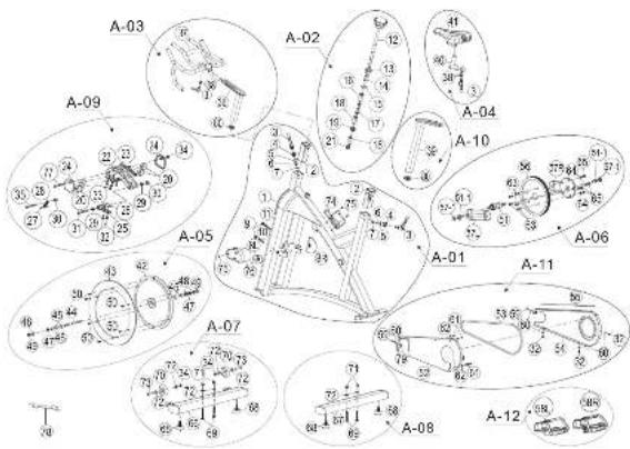
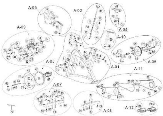
GR3 EXPLODED VIEW
text_image
Technical diagram of a mechanical assembly with numbered components and labeled parts
GR3 PARTS LIST

ENGLISH
| NO. | DESCRIPTION: CTY | ||
| FRAME | |||
| 1 | FRAME 1 | ||
| 2 | SIF FIVE 2 | ||
| 3 | NIVUSTABLE KNGB 3 | ||
| 4 | ALLEN BOLT 2 | ||
| 5 | ALLEN NUT 2 | ||
| 6 | BOTTLE CAGE 1 | ||
| 7 | WATER BOTTLE 1 | ||
| BRAXE | |||
| 8 | TENSION CONTROL 1 | ||
| 9-1 | SPACER | 1 | |
| 9-2 | HELICAL COMPRESSION SPRING | 1 | |
| 9-3 | SQUARE NUT | Φ1/ST | 1 |
| 9-4 | ALLON NUT | M6 | 1 |
| 9-5 | CAP NUT | M6 | 1 |
| 9 | BRAXE PAD ASSEMBLY | 1 | |
| HANDLEBAR | |||
| 10 | HANDI BAR | 1 | |
| SEAT POST | |||
| 11 | SEAT POST | 1 | |
| NO. | DESCRIPTION | QTY |
| 12 | SFAT SLICPR | 1 |
| 13 | FND CAP | 1 |
| 14 | SLIFEVE | 1 |
| 15 | SPADDLE | 1 |
| 16 | END CAP | 1 |
| FLYWHEEL | ||
| 17 | FLYWHEEL ASSEMBLY | 1 |
| TRANSMISSION | ||
| 18 | PLDAL (L) | 1 |
| 19 | PLDAL (L) | 1 |
| 20 | CHAIN WHEEL CP 1 | |
| 21 | CRANK - DP | 1 |
| 22 | INNPR CHAIN GUARD | 1 |
| 23 | SELF - TAPPING SCREW 1 | |
| 24 | CHAIN | 1 |
| 25 | CRANK CAP | 2 |
| 26 | SELF - TAPPING SCREW 8 | |
| 27 | SELF - TAPPING SCREW 2 | |
| 28 | RB BOLT | 2 |
| 29 | OUTER CHAIN GUARD WITHOUT STICKER | 1 |
| NO. | DESCRIPTION | QTY. |
| 29 | ALL EN ROLT | 1 |
| 30 | BOTTOM BRACKET 1 | |
| 31 | CHAIN GUARD SPACER | 6 |
| FRONT STABILIZER | ||
| 32 | WASHER | 4 |
| 33 | FRONT STABILIZER | 1 |
| 34 | ALLEN ROLT | 4 |
| REAR STABILIZER | ||
| 35 | REAR STABILIZER | 1 |
| 36 | CHAIN GUARD COVER | 1 |
F25_D13-4 CMr1_4_Amd 24-25

ENGLISH
2524
42518 913 AM
GR5 EXPLODED VIEW

text_image
A-09 A-03 A-04 A-06 A-02 A-10 A-01 A-12 A-06 A-11 A-07 A-08 A-12 A-06ENGLISH
F214_BH3-4 CMr1_4_A Ind 20-27
GR5 PARTS LIST
| NO. | DESCRIPTION: QTY | |
| FRAME ASSEMBLY (A-01) | ||
| 1 | FRAME 1 | |
| 2 | STAINLESS STEEL PLATE 1 | |
| 3 | PILLIP SCREW 5 | |
| 4 | SELF-TAPPING SCREEN 1 | |
| 5 | SWEAT GUARD (L) 1 | |
| 6 | SWEAT GUARD (R) 1 | |
| 8 | FLYWHEEL DROPOUT PLATE (L) 1 | |
| 8 | FLYWHEEL DROPOUT PLATE (R) 1 | |
| 7 | ALLLEN OULT | 2 |
| 9 | END CAP | 4 |
| 9 | LEFT TAPPING SCREEN | 4 |
| 10 | ANTHOLD PERRY GURRER PAD | 2 |
| 12 | FRONT DECORATIVE COVER | 1 |
| 13 | QUICK RELEASE | 2 |
| 14 | QUICK RELEASE NUT | 2 |
| 15 | QUICK RELEASE RECEPTOR | 2 |
| 16 | QUICK RELEASE SPRING | 2 |
| 17 | WASHER | 2 |
| 18 | SLEEVE | 2 |
| NO. | DESCRIPTION | QTY | |
| 21 | A TINROLT | 1 | |
| 22 | WAS-FT | 1 | |
| 23 | EMERGENCY LEVEL ER | 1 | |
| 30 | EMERGENCY LEVELER DUGAL | 1 | |
| 56 | SELF TAPPING SCREW | 2 | |
| 82 | LOCK NUT | 1 | |
| TENSION CONTROL KNOS SFT (A-2) | |||
| 16 | TENSION CONTROL KNOS | 1 | |
| 26 | SPACER | 1 | |
| HANDLEBAR SET (A-3) | |||
| 31 | HANDLEBAR | 1 | |
| SBAT PAD ADJUSTMENT SFT (A-3) | |||
| 36 | SBAT SLIDPR | 1 | |
| 37 | SACOLL | 1 | |
| FLYWHEEL ASSEMBLY (A-3) | |||
| 32 1 | MAGNET | 1 | |
| 36 | FLYWHEEL | 1 | |
| 46 | HUB SET | 1 | |
| 46 1 | FLANGE NUT | 2 | |
| 46 2 | WAS-TER PH2*32*2.0 | 2 | |
ENGLISH
2726
42018 913 AM
| NO. | DESCRIPTION QTY | ||
| 41 | HLR COVER 1 | ||
| 42 | LOCKED BING 1 | ||
| 43 | SMALL PULLEY 1 | ||
| FLYWHEEL DGCAL 2 | |||
| CRANK AXLE SET (A-06) | |||
| 45L | CRANK L1 1 | ||
| 46L | CRANK L R 1 | ||
| 46 | BOTTOM BRACKET 1 | ||
| 46-1 | BB NUT | M10"1.5 | 2 |
| 46-2 | CRANK CAP | 2 | |
| 47 | FLYNGE BOLT CAP | 1 | |
| 58 | BQ PULLEY | 1 | |
| 59 | ALRV RG T2 | ||
| 60 | ALLEN BOLT | 6 | |
| 61 | SPRING WASHER | 6 | |
| 62 | LOCK NUT | 6 | |
| FRONT STABILIZER ASSEMBLY (A-07) | |||
| 71 | ALLEN BOLT 2 | ||
| 72 | WASHER | 8 | |
| 34 | STABILIZER DGCAL | 2 | |
| NO. | DESCRIPTION | QTY |
| 62 | LOCK NUT | 2 |
| 64 | FRONT STABILIZER | 1 |
| 65 | CARRIAGE BOLT | 2 |
| 66 | CAP NUT | 2 |
| 67 | ADJUSTABLE LEVELER | 2 |
| 68 | TRANSPORTATION WHEEL BLACK | 2 |
| REAR STABILIZER ASSEMBLY (ACR) | ||
| 22 | WASHER | 2 |
| 31 | STABILIZER DECA. 2 | |
| 65 | CARRIAGE BOLT | 2 |
| 65 | CAP NUT | 2 |
| 67 | ADJUSTABLE LEVELER | 2 |
| 69 | REAR STABILIZER | 1 |
| DRANGE PAD ASSEMBLY (AVR) | ||
| 24 | ACOUSTIC GROWMET | 1 |
| 25 | CALIPER | 1 |
| 25-1 | STOPPER | 1 |
| 26 | SQUARE NUT | 1 |
| 27 | WASHER | 2 |
| 28 | LICK NUT | 1 |
| NO. | DESCRIPTION QTY | |
| 29 | BREAK SHOF SET (1) | 1 |
| 30 | BREAK SHOF SET (2) | 1 |
| 35 | LOCK NUT | 1 |
| SEAT POST SET (A/10) | ||
| 13 | QUICK RELEASE | 1 |
| 14 | QUICK RELEASE NUT | 1 |
| 15 | QUICK-RELEASE RECEPTOR | 1 |
| 16 | QUICK-RELEASE SPRING | 1 |
| 17 | WASHER | 1 |
| 18 | SHELL | 1 |
| 30 | SELF TAPPING SCREW | 1 |
| 38 | ANTI-SLIPPERY RUBBER PAD | 1 |
| COVER SET (A+1) | ||
| 3 | FILLIP SCREW | 1 |
| 9 | SELF TAPPING SCREW | 2 |
| 11 | SELF-TAPPING SCREW | 2 |
| 32 | HEX NUT | 1 |
| 48 | INNER CHAIN GUARD | 1 |
| 49 | WASHER | 4 |
| 51 | FILLIPS SCREW | 4 |
| NO. | DESCRIPTION | QTY |
| 52 | CHAIN CHARD SPACER | 2 |
| 53 | FRONT-CHAIN CHARD BLACK | 1 |
| 54 | OUTER CHAND CHARD | 1 |
| 55 | BELT | 1 |
| 57 | PHILLIP SCREW | 2 |
| 63 | RUBBER STRIPPING | 1 |
| PEDAL SET (A-12) | ||
| 4/R | PEDAL (R) | 1 |
| 4/L | PEDAL (L) | 1 |

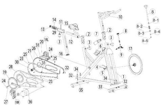
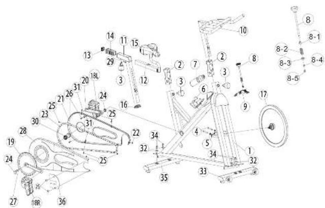
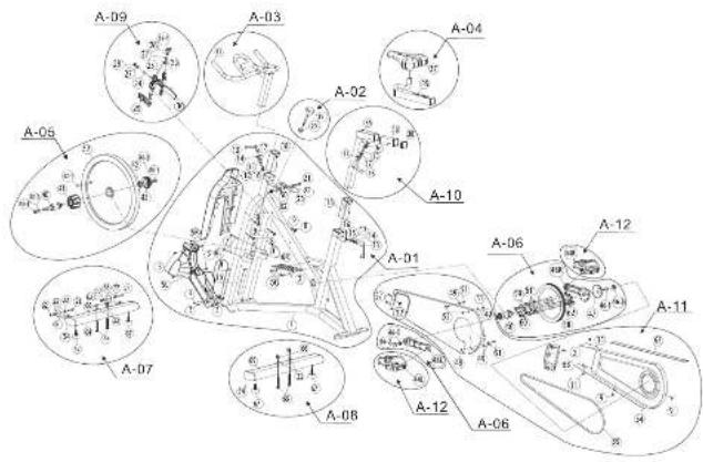
GR6 EXPLODED VIEW

text_image
A-03 A-02 A-09 A-04 A-10 A-05 A-01 A-06 A-07 A-11 A-08 A-12ENGLISH
F2'5_D13-4 CMr1_4_Amd: 32-21
GR6 PARTS LIST
| NO. | DESCRIPTION | QTY |
| FOAMF ASSEMBLY (A-01) | ||
| 1 | FRAME | 1 |
| 2 | S L EVE | 2 |
| 3 | QUICK RELEASE | 1 |
| 4 | QUICK RELEASE NUT | 2 |
| 5 | WASHER | 2 |
| 6 | QUICK-RELEASE RECEPTOR | 2 |
| 7 | QUICK RELEASE SPRING | 2 |
| 8L | FLYWHEEL DROP OUT PLATE (L) | 1 |
| 9K | FLYWHEEL DROP OUT PLATE (K) | 1 |
| 9 | END CAP | 2 |
| 10 | ALIEN BOLT | 1 |
| 11 | ALIEN BOLT | 1 |
| 14 | WATCH BUTTLE CABLE | 1 |
| 15 | PHILLIPS SCREW | 3 |
| 16 | FRONT FORK SHIELD | 1 |
| TENSION CONTROL KNOS SET (A-02) | ||
| 12 | TENSION CONTROL | 1 |
| 13 | POSITIONING NUT | 1 |
| 14 | SPACK | 1 |
| NO. | DESCRIPTION | QTY |
| 15 | WASHER | 1 |
| 16 | NYLON POSITIONING CAP | 1 |
| 17 | COMPRESSION SPRING | 1 |
| 18 | NYLON HOLDER | 2 |
| 19 | ADJUSTMENT NUT | 1 |
| 21 | CAP NUT | 1 |
| HANDLEAR SET (A-05) | ||
| 3 | QUICK RELEASE | 1 |
| 36 | HANDLEAR STEM | 1 |
| 37 | HANDLUXAR | 1 |
| 38 | WASHER | 2 |
| 50 | END CAP | 1 |
| SEAT PAD ADJUSTMENT SET (A-05) | ||
| 3 | QUICK RELEASE | 1 |
| 38 | WASHER | 2 |
| 40 | SEAT SLIDER | 1 |
| 41 | SEAT | 1 |
| FLYWHEEL ASSIFUS BY (A-05) | ||
| 42 | FLYWHEEL | 1 |
| 43 | ALUMINUM RING | 1 |

ENGLISH
3130
42018 913 AM
| NO. | DESCRIPTION QTY | |
| 44 | HJR AXE F 1 | |
| 45 | READING 4 | |
| 46 | HJR SPACER 1 | |
| 47 | ALLEN NUT 3 | |
| 48 | WASHER 3 | |
| 49 | FLANGE NUT 2 | |
| 50 | ALLEN BOLT 8 | |
| - | FLYWHEEL DECAL 2 | |
| CRANK AXLE SET (A-06) | ||
| 51 | DOTTOM GRACKLT 1 | |
| 51.1 | CRANK BOLT 2 | |
| 56 | RIG PULLIEY | 1 |
| 57 | CRANK (L) 1 | |
| 57.1 | CRANK (R) | 1 |
| 57.1 | CRANK CAP 2 | |
| 53 | ALLEN BOLT | 6 |
| 54 | SPRING WASHER | 4 |
| 55 | LOCKED NUT 4 | |
| FRONT STABILIZER ASSEMBLY (A-07) | ||
| 34 | LOCKED NUT 2 | |
| NO. | DESCRIPTION | QTY |
| 66 | FRONT STABILIZER | 1 |
| 68 | ADJUSTABLE FLYPER FD | 2 |
| 69 | CARRIAGE BOLT 2 | |
| 70 | TRANSPORTATION WHEEL BLACK | 2 |
| 71 | CAP NLT | 2 |
| 72 | WASHER | 6 |
| 73 | ALLEN BOLT | 2 |
| RLEAR SPINDLICER ASSEMBLY (AOK) | ||
| 67 | FLAIR STABILIZER | 1 |
| 68 | ADJUSTABLE LEVILLOR | 2 |
| 69 | CARRIAGE BOLT 2 | |
| 71 | CAP NLT | 2 |
| 72 | WASHER | 2 |
| DRANGE PAD ASSEMBLY (AOK) | ||
| 20 | MAGNET | 4 |
| 22 | MAGNET BRACKET | 1 |
| 23 | WOOL FELTS SUPPORTING BASE | 1 |
| 24 | MAGNET BRACKET SHIELD | 2 |
| 25 | MAGNET ADJUSTMENT BRACKET | 1 |
| 25 | MAGNET BRACKET FIXER | 1 |
| NO. | DESCRIPTION GTY | |
| 27 | SPRING-HOX DER | 1 |
| 28 | SPRING | 1 |
| 29 | BRAKE CUSHION | 2 |
| 30 | LOCKED NOT 2 | |
| 31 | PHILLIPS SCREW | 1 |
| 32 | PHILLIPS SCREW | 2 |
| 33 | ALLEN BOLT | |
| 34 | LOCKED NOT 1 | |
| 77 | PHILLIPS SCREW | 1 |
| SEAT POST SET (A-10) | ||
| 39 | SEAT POST | 1 |
| 80 | END CAP | 1 |
| COVER SET (A-11) | ||
| 32 | PHILLIPS SCREW | 3 |
| 52 | INNER CHAIN GUARD | 1 |
| 53 | BELT | 1 |
| 54 | OUTER CHAIN GUARD | 1 |
| 55 | ANTI-SUPPERY RUBBER PAD | 1 |
| 59 | PHILLIPS SCREW | 2 |
| 80 | WASHER | 5 |
| NO | DESCRIPTION | QTY |
| 61 | PHILLIPS SCREW | 4 |
| 82 | WAS-PE | 4 |
| PEDAL SET (A-12) | ||
| 58R | RIGHT PEDAL (R) | 1 |
| 58L | LEFT PEDAL (L) | 1 |

ENGLISH
H2'5_D13-4 CM r1_4_A ind 34-25 4/20/18 9:13 AM

natural_image
Line drawing of a stationary exercise bike with wheels and suspension components (no text or symbols)natural_image
Technical line drawing of a stationary exercise bike with labeled components (A, B), no text or symbols present.(GR6 DARGESTELLT)
SATTELEINSTELLUNG
H2'5_D13-4 CMr1_4_Amtd 42-43 4/2018 9:13 AM
text_image
Technical diagram of a stationary exercise machine with numbered components and labeled partstext_image
Technical diagram of a mechanical assembly with numbered components for identification

F25_D13-4 CMr1_3_Amd 44-45
42M18 913 AM
GR5 MONTAGE SCHRITT 1

text_image
Technical diagram of a stationary exercise machine with numbered components for identificationtext_image
Technical diagram of an exercise bike with numbered components for identificationFCS_BFB-4CMr1_3_Amd 48-47
42M18 913 AM
GR6 MONTAGE SCHRITT 1

text_image
Technical diagram of a mechanical assembly with numbered components for identificationtext_image
Technical diagram of an exercise bike with numbered components for identificationtext_image
Technical diagram of an exercise bike with numbered components for identificationtext_image
Technical diagram of a mechanical exercise machine with numbered components and labeled parts
GR3-TEILELISTE

HOSCH
| NO. | FESCHREIBUNG VERICE | |||
| SAHVEN | ||||
| 1 | SAHVEN 1 | |||
| 2 | HULSE 2 | |||
| 3 | LENSSTELLWALKER KNOFF | 3 | ||
| 4 | INBUSSICHRADE | 2 | ||
| 5 | INBUSBUTTER | 2 | ||
| 6 | RASCHENHALTER | 1 | ||
| 7 | WASSCRIFASCHE | 1 | ||
| JREMISE | ||||
| 8 | ZOGMIGILLING | 1 | ||
| 9-1 | ABSTANDSHALTER | 1 | ||
| 9-2 | SOHTALUBDRUCKFEDER | 1 | ||
| 9-3 | VIFRKANTIVUTTER | Φ13'ST | 1 | |
| 9-4 | INDUSVUTTER | MΩ | 1 | |
| 9-5 | DERKAMRTVUTTER | MΩ | 1 | |
| 9 | DREWSBELAGBAJORUPPE | 1 | ||
| LEKKER | ||||
| 10 | LENKER | 1 | ||
| SATTR.STUTZE | ||||
| 11 | SATTLISUTZE | 1 | ||
| NR. | BISCHIRUNG | MFNCF |
| 12 | SATTE SCHITTEN | 1 |
| 13 | FENKAPPE | 1 |
| 14 | HOLSE | 1 |
| 15 | SATTEL | 1 |
| 16 | ENCKAPPE | 1 |
| SCHWACHAD | ||
| 17 | SCHWUNGERAGRIEURPPE | 1 |
| ÜGERSLIZUNG | ||
| 18 | PLDAL (R) | 1 |
| 19 | PLDAL (L) | 1 |
| 20 | KETTENRAD - CP | 1 |
| 21 | KUTREL - CP 1 | |
| 22 | INNPRER KETTPNSCHUTZ | 1 |
| 23 | THEUSCHRAUBE | 1 |
| 24 | KETTE | |
| 25 | KURBELKAPPE | 2 |
| 26 | TREBSCHRAUBE | 8 |
| 27 | TREBSCHRAUBE | 2 |
| 28 | RB-SCHRAUBE | 2 |
| 29 | AUSICER KETTENSCHUTZ CHINE AUTRÜBER | 1 |
| NO. | FISCHERUNG, MPNCF | |
| 29 | INBUSSCHRAUBE 1 | |
| 30 | UNTRRF HALTFÜNG 1 | |
| 31 | KETTENSCHUTZARSTANDHALTER 6 | |
| STABILISATOR VÖKNL | ||
| 32 | UNTERLIDGSCHEBE 4 | |
| 33 | STABILISATOR VÖKNE 1 | |
| 34 | INBUSSCHRAUBE 4 | |
| STABILISATOR HINTEN | ||
| 35 | STABILISATOR HINTEN 1 | |
| 35 | KETTENSCHUTZARJOLCKUNG 1 | |
F24_015-4 CMr1_4_Amd: 38-37

DEUTRCH
5756
42518 913 AM
H2'5_D13-4 CMr1_4_Amd 68-67/2018 9:13 AM
BEDIENING VAN DE INDOORFIETS

NEDERLANDS
66

DE INDOORFIETS VERPLAATSEN
natural_image
Line drawing of a stationary exercise bike with rotating wheel and support mechanism (no text or symbols)text_image
Technical diagram of a stationary exercise bike with labeled components A and B(GR6 AFGEBEELD)
ZADELAFSTELLING
H25_D13-4 CMr1_A_Ind 74-7542018 9:13 AM
MEEGELEVERDE HOOFDONDERDELEN:
text_image
Technical diagram of a stationary exercise machine with numbered components and labeled partstext_image
Technical diagram of a mechanical assembly with numbered components for identificationF25_D13-4 CMr1_4_Amd 78-77
42M18 913 AM
GR5 MONTAGE STAP 1

| GEREEDSCHAP VOOR STAP 1: | ||
| NR. BESCHRÜNG AANTAL | ||
| 1 | STABLISATOR ACHTERKANT 1 | |
| 2 | BOUTEN 4 | |
| 3 | MOERDY 4 | |
| 4 | SLUITRIGEN 4 | |
| 5 | SLEUTEL | 1 |
| 6 | STABLISATOR VOORKANT | 1 |

text_image
Technical diagram of a stationary exercise machine with numbered components for identificationtext_image
Technical diagram of an exercise bike with numbered components for identificationF25_BFB-4 CMr1_3_Amd 78-79


42518 913 AM
GR6 MONTAGE STAP 1

| GEREEDSCHAP VOOR STAP 1: | ||
| NR. | BESCHRUMING AANTAL | |
| 1 | BOUTEN 4 | |
| 2 | MODERN 4 | |
| 3 | SUITRIVGEN (MR) 4 | |
| 4 | STABILISATOR VOORKANT | 1 |
| 5 | STABILISATOR ACHITERKANT | 1 |
| 6 | SLEUTEL 1 | |
text_image
Technical diagram of a mechanical assembly with numbered components for identificationF25_DFB-4 CMr1_4_Amd 80-81
GR6 MONTAGE STAP 2
| GEREEDSCHAP VOOR STAP 2: | ||
| NR. B | SCHRUWING AANTAL | |
| 6 | SLEUTEL 1 | |
| 7 | STULRMAST 1 | |
| 8 | ZADELPEN 1 | |
| 9 | REO-TERPEDAAL 1 | |
| 10 | LINKERPEDAAL 1 | |
text_image
Technical diagram of an exercise bike with numbered components for identificationtext_image
Technical diagram of an exercise bike with numbered components for identificationOPENGEWERKTE WEERGAVE GR3
text_image
Technical diagram of a mechanical assembly with numbered components and labeled parts
NEDERLANDS
8786
NEUERLANDS
F2'5_D13-4 CMr1_4_Amd 88-87
42M18 913 AM
ONDERDELENLIJST GR3

NEDERLANDS
88
| MT. | FISCHRUNING ANTAL | ||
| FRAME | |||
| 1 | FRAME 1 | ||
| 2 | MOF 2 | ||
| 3 | VURSTEELWARE KNOP | 3 | |
| 4 | INUSBOUT 2 | ||
| 5 | INBUSMOER | 2 | |
| 6 | CONHOUDER | 1 | |
| 7 | DON | 1 | |
| HLM | |||
| 8 | SPANNINGSCONTROLL | 1 | |
| 9-1 | AFSTANDGSTUK | 1 | |
| 9-2 | SCHNORFFCOMPRESSIEVER | 1 | |
| 9-3 | VIFRKANTF MOER | Φ13'ST | 1 |
| 9-4 | INDUSWOLR | MG | 1 |
| 9-5 | COPWOLR | MG | 1 |
| 9 REMELOCKNONTAGE | 1 | ||
| STULR | |||
| 10 | STUUR | 1 | |
| ZADEL PEN | |||
| 11 | ZADELPLN | 1 | |
| NR. | BESCHRUNING | AANTAL |
| 12 | ZADRI SCHUIF | 1 |
| 13 | FINDKAP | 1 |
| 14 | MOF | 1 |
| 15 | ZADLL | 1 |
| 16 | ENDKAP | 1 |
| VI ERCWIFI | ||
| 17 | VIEGAWEL MONTAGE | 1 |
| TRANSMISSIL | ||
| 18 | PLDVAL (R) | 1 |
| 19 | PLDVAL (C) | 1 |
| 20 | KETTINGWIEL CP | 1 |
| 21 | KTLIKAS - CP | 1 |
| 22 | BINNENSTF KETTINGKAST | 1 |
| 23 | ZLU TAPPENDL SCHROEF | 1 |
| 24 | KETTING | 1 |
| 25 | KRIUKASKAP | 2 |
| 26 | ZELUTAPPENDE SCHROEF | 8 |
| 27 | ZELUTAPPENDE SCHROEF | 2 |
| 28 | BR BOUT | 2 |
| 29 | BATLENSITE KETT NGRAST ZUNDER STICKER | 1 |
| NR. | FISCHLIVING AANTAI | |
| 29 | INBUSOUT 1 | |
| 30 | CANDRATIE BRUGFI 1 | |
| 31 | AFSTANDSITUK VOOR OF KETTINGKAST 8 | |
| STABILISATOR VOORKANT | ||
| 32 | SUITRING 4 | |
| 33 | STABILISATOR VOORKANT 1 | |
| 34 | INBUSOUT 4 | |
| STABILISATOR ACHTERKANT | ||
| 35 | STABILISATOR ACHTERKANT 1 | |
| 36 | AVOLKPLAY VOOR DE KETTINGKAST 1 | |
F24_B13-4 CMr1_4_A ind 89-89

NEDERLANDS
89
42018 913 AM
OPENGEWERKTE WEERGAVE GR5
text_image
A-09 A-03 A-04 A-06 A-02 A-10 A-01 A-12 A-06 A-11 A-07 A-12 A-08 A-06NEVERLANDS
F24_BH3-6 CMr1_4_Amd 90-01
ONDERDELENLIJST GR5
| NR. | FRECHIRLING AANTAI | |
| FRAMEVOMNTAGE (A-01) | ||
| 1 | FRAME 1 | |
| 2 | RIESTRUSTALIEN P. AAT 1 | |
| 3 | KRUSKOPSCHROEF 8 | |
| 4 | ZELIFTAPPENDE SCHROEF 1 | |
| 5 | ZLIFETBESTENDIGE BESCHERMING (LI 1) | |
| 6 | ZWIFETBESTENDIGE BESCHERMING (RI 1) | |
| 7 | VLUGSWILLDUCUSLEPLAATIE (LI 1) | |
| 8 | RVLEGWILDUCUSLEPLAATIE (RI 1) | |
| 9 | NDUSOUT 2 | |
| 10 | ENDCKAP 4 | |
| 11 | ZELIFTAPPENDE SCHROEF 4 | |
| 12 | TURERDEN AATSUDUKUSSPN | 2 |
| 13 | DUCOKATELY VOONIKANT | 1 |
| 14 | SNELSPANNER | 2 |
| 15 | MOER SNELSPANNER | 2 |
| 16 | ANSLUITING SNELSPANNER | 2 |
| 17 | VEER SNELSPANNER | 2 |
| 18 | S. UITRING | 2 |
| 19 | MGI | 2 |
| NO. | BESCHRILVING | AANTAI | |
| 21 | INRUSROUT | 1 | |
| 22 | SLUTTING | 1 | |
| 23 | NOCOKWELLIFERDER | 1 | |
| 30 | STICKER NOONVILLELERDER | 1 | |
| 36 | ZELFTAPPENDE SCHROEF | 2 | |
| 52 | BOROMDER | 1 | |
| SET SPANNINGSCONTROL-KNOP (A-02) | |||
| 18 | SPANNINGSCONTROL-KNOP | 1 | |
| 20 A | STANDISSTUK | 1 | |
| STURSET (A-03) | |||
| 31 S | STUUR | 1 | |
| AFSTELLINCSSET ZITKUISSEN (A-04) | |||
| 38 7 | MOFR.SCHUIF | 1 | |
| 37 2 | ONCEL | 1 | |
| YUDSWIELVONTAGE (A-05) | |||
| 32 1 | WAGNEET | 1 | |
| 39 V | LIEGWIEL | 1 | |
| 40 N | MAFSET | 1 | |
| 46-1 | FLJENSMOER | 2 | |
| 49-2 | SLUTRING | 410°42'12.0 | 2 |
NEDERLANDS
9190
42M'18 913 AM
| NE | BESCHLIVING AANTAL | ||
| 41 | MAFAFDEFKING | 1 | |
| 42 | VROGENDELOR RING | 1 | |
| 43 | FINE WIELSCHUF | 1 | |
| VLEGNIELSTICKER | 2 | ||
| ASSET KRUKAS (A-08) | |||
| 43L | KRUKAS (L) | 1 | |
| 450 | KRUKAS (R) | 1 | |
| 46 | ONOLRSTE DOUGEL 1 | ||
| 45-1 | B6 NOER | M10*1.5 | 2 |
| 45-2 | KRUKASKAF | 2 | |
| 47 | FLUNSDOUTKAP | 1 | |
| 58 | CROTTE PIMASCHUF | 1 | |
| 59 | INJUSBOUT | 2 | |
| 60 | INJUSBOUT | 6 | |
| 61 | VEHRKING | 5 | |
| 62 | BOGRACER | 5 | |
| MONTAGE VAN DE VOORSTE STABILISATOR (A-07) | |||
| 21 | INJUSBOUT | 2 | |
| 22 | LUTTING | 8 | |
| 34 | STABILISATORSTICKER | 2 | |
| NR. | RESOHLVING | AANTAL |
| 82 | BOROWDER | 2 |
| 83 | STABILISATOR VOODIKANT | 1 |
| 85 | SLOTBOUT | 2 |
| 88 | DOPWDER | 2 |
| 87 | VERISTELBAPE SIGALISERDEH | 2 |
| 88 | TRANSORTWIEL ZWART | 2 |
| STABILISATOR ACHTRIKANT (A-88) | ||
| 22 | SUITRING | 2 |
| 31 | STABILISATORSTICKER | 2 |
| 65 | SLOTBOUT | 2 |
| 69 | DOPWDER | 2 |
| 67 | VERISTELBAPE ECALISERDEH | 2 |
| 69 | STABILISATOR ACHTRIKANT | 1 |
| REDUORWONTAGL (A-99) | ||
| 24 | AKOCSTISCH RUBBER | 1 |
| 25 | RENEVLAVI | 1 |
| 25-1 | STOP | 1 |
| 25 | VERKANTE MOER | 1 |
| 27 | SUTRING | 2 |
| 29 | DURGNOVER | 1 |
| NR. | RFSCHIRVING AANTAI | |
| 29 | RFSCHORNSFT (I) 1 | |
| 30 | RFSCHORNSFT (II) 1 | |
| 35 | RDSRKWDER 1 | |
| ZADELPENSFT (A-10) | ||
| 13 | SNELEPANNER 1 | |
| 14 | MOER SNELEPANNER 1 | |
| 15 | ANSLUITAG SNELEPANNER 1 | |
| 16 | VCLR SNELEPANNER 1 | |
| 17 | SUITRING 1 | |
| 18 | MOT 1 | |
| 30 | ZEUTTAPPENDE SCHROEF 1 | |
| 38 | FURBEREN ANTSILIPKUSSRN 1 | |
| AFFEKST (A-11) | ||
| 3 | KRUSKOPSCIKROEF 1 | |
| 9 | ZEUTTAPPENDE SCHROEF 2 | |
| 11 | ZEUTTAPPENDE SCHROEF 2 | |
| 32 | ZESKANTMOER | 1 |
| 45 | BRKNENSTE KETTINGKAST | 1 |
| 49 | SUITRING 4 | |
| 51 | KRUSKOPSCIKROEF 4 | |
| NO. | BESCHRIKVNC | AANTAL |
| 50 | AFSTANDSRTUK VOOR OF KETTINGKAST | 2 |
| 51 | KEFTTINGKAST VOOR ZHAART | 1 |
| 51 | BUITENSTE KETTINGKAST | 1 |
| 56 | DAVD | 1 |
| 57 | KRUSKOPSCHROCEF | 2 |
| 63 | RUBBEREN STRIPPEN | 1 |
| PEDAAI S&T (A-12) | ||
| 41R | FLUAVA (R) | 1 |
| 41L | PEDAAI (L) | 1 |

OPENGEWERKTE WEERGAVE GR6
text_image
A-03 A-02 A-09 A-04 A-10 A-05 A-01 A-06 A-11 A-07 A-08 A-12NEDERLANDS
F215_BF13-4 CMr1_4_A Ind 94-05
ONDERDELENLIJST GR6
| NR. | FRAVPMONTAGE (A-01) | |
| 1 | FRAME 1 | |
| 2 | MOF 2 | |
| 3 | SHELLSPANNER 1 | |
| 4 | MDR SNEELSPANNER 2 | |
| 5 | SLITTING 2 | |
| 6 | ANSLUTING SNELSPANNER 2 | |
| 7 | VLCR SNELSPANNER 2 | |
| 8 | VLIGWILLELGEUSPLAATIE 3U 1 | |
| 9 | VLIGWILLELGEUSPLAATIE 3K 1 | |
| 9 | ENDCKAP 2 | |
| 10 | INBUSROUT | 1 |
| 11 | INBUSROUT | 1 |
| 14 | WILKBUDDONHOUDLR | 1 |
| 13 | KALIKKOPSCHROLE | 3 |
| 15 | BESCHERMKAP VOORVORK | 1 |
| SET SPANNIVGSCONTROLE(NOP (A-02)) | ||
| 12 | SPANNIVGSCONTROLE | 1 |
| 13 | RONTMOER | 1 |
| 14 | AT STANDSTUK | 1 |
| NO. | RESCHILVINC | AANTAL |
| 16 | SLUTRING | 1 |
| 16 | NYLON TICHKAAT | 1 |
| 17 | COMPOESSIVEER | 1 |
| 18 | NYLON HOULDER | 2 |
| 19 | AFSTEELVOER | 1 |
| 21 | DOFINDER | 1 |
| STUURSET (A-03) | ||
| 3 | SNLLSPANNLER | 1 |
| 36 | STUURPEN | 1 |
| 37 | STUKR | 1 |
| 38 | SLUITRING | 2 |
| 39 | ENDKAT 1 | |
| AFSTEEL INCSSET ZITKUSSPN (A-04) | ||
| 3 | SNLLSPANNLER | 1 |
| 38 | SLUITRING | 2 |
| 40 | ZADELSCHUIF | 1 |
| 41 | ZODEL | 1 |
| VLRCWIELVONTAGE (A-05) | ||
| 42 | VEGWEL | 1 |
| 43 | ALUMINIUM RING | 1 |

NEDERLANDS
9594
42018 913 AM
| NL BESCHRÜNG AANTAL | ||
| 41 NAFAS | 1 | |
| 46 I AGET | 4 | |
| 46 NAFAFSTANDRSTUK | 1 | |
| 47 INUSMOLK | 3 | |
| 48 SLUITING | 3 | |
| 49 FLENMDER | 2 | |
| 50 INSUBSOUT 6 | ||
| - VILCRAMILLSTICKLER | 2 | |
| ASSET KRUKAS (A/08) | ||
| 51 ONDORSTE DBUGCL | 1 | |
| 51.1 KRUKASBOUT 2 | ||
| 56 CROTE DIPASCHUF | 1 | |
| 571 KRUKAS (1) | 1 | |
| 5YR KRUKAS ING 1 | ||
| 5YI KRUKASKAF | 2 | |
| 53 INSUBSOUT 5 | ||
| 54 VEERRING | 4 | |
| 56 VERGRENDELCE MOER 4 | ||
| MONTAGE VANDE VOORDSTE STABILISATOR (A/07) | ||
| 54 VORGRENDELCE MOER 2 | ||
| NR. | BESCHRUNING | AANTAL |
| 68 | STARIISATOR VOODKANT | 1 |
| 69 | VROSTER/RADF REAJ ISFERRED 2 | |
| 70 | SLOTBCUT | 2 |
| TRANSFORMWEL Zwart | 2 | |
| 71 | DOPVICER | 2 |
| 72 | SLUITRING | 6 |
| 73 | INBURGOUT | 2 |
| STABILISATOR ACHITLRKANT (A-88) | ||
| 67 | STABILISATOR ACHITLRKANT | 1 |
| 69 | VORSTILLJAKL DEALSLEHDDR 2 | |
| 69 | SLOTBCUT | 1 |
| 71 | DOPVICER | 2 |
| 72 | SLUITRING | 2 |
| RENDLRKONTOAGL (A-89) | ||
| 20 | MAGNEET 4 | |
| 22 | MAGNETBEUGEL | 1 |
| 23 | CKDERSTEUNENDE BASIS VAN WOLVILT | 1 |
| 24 | MAGNETBEUGELAFSCHERING | 2 |
| 25 | MAGNETISCHE AFSTER BEUGEL | 1 |
| 28 | MAGNETISCHE STOUNDLVESTIGING | 1 |
| NR. | VFSCHRILVNC AANTAI | |
| 27 | VFFRHOUFDR 1 | |
| 28 | VFFD 1 | |
| 29 | RENDMPING 2 | |
| 30 | VLHIGKNDLLDL MOLK 2 | |
| 31 | KRUSKOPSCHROEF 1 | |
| 32 | KRUSKOPSCHROEF 2 | |
| 33 | IRBUSOUT 4 | |
| 34 | VLHIGKNDLLDL MOLK 1 | |
| 77 | KRUSKOPSCHROEF 1 | |
| ZACCLPLNSLT (A-10) | ||
| 39 | ZACLLPEV 1 | |
| 83 | PACKAP 5 | |
| AFDPKSFT (A-11) | ||
| 32 | KRUSKOPSCHROEF 3 | |
| 52 | BRINENSTE KETTINGKAST 1 | |
| 53 | BAND 1 | |
| 54 | BUTENSTE KETTINGKAST 1 | |
| 55 | RUBEREN ANTISUPXUSSEN 1 | |
| 59 | KRUSKOPSCHROEF 2 | |
| 80 | SUITRING | 5 |
| M1 | BESCHRIUMC | AANTAI |
| 61 | KRUISKOPSCHROFF | 4 |
| 62 | SLUTTING | 4 |
| PEDAL SET (A-12) | ||
| SIR | RECHTERPEDAL (R) | 1 |
| SRL | LINKERPEDAL (L) | 1 |

NEDERLANDS
H2'5_D13-4 CM r1_4_A mds 98-02-4/M/18 9:13 AM

FONCTIONNEMENT DU VÉLO D'APPARTEMENT

FRANCIER
98

COMMENT DÉPLACER LE VÉLO D'APPARTEMENT
natural_image
Line drawing of a stationary exercise bike with rotating wheel and support frame (no text or symbols)natural_image
Technical line drawing of a stationary exercise bike with labeled components (A, B), no text or symbols present.(VUE D'ENSEMBLE DU GR6)
RÉGLAGE DE LA SELLE
text_image
Technical diagram of a stationary exercise machine with numbered components and labeled partstext_image
Technical diagram of a mechanical assembly with numbered components for identification

H2'5_013-4 CMr1_4_A Ind 108-109
42M18 913 AM

GR5 MONTAGE ÉTAPE 1
| SACHET DE VISSERIE POUR ÉTAPE DE MONTAGE 1 : | ||
| N° DESCRIPION QTE | ||
| 1 | STABLISATEUR ARRÊRE 1 | |
| 2 | VIS 4 | |
| 3 | ECROCUS 4 | |
| 4 | RONDELLES | 4 |
| 5 | CLÉ 1 | |
| 6 | STABLISATEUR AVANT | 1 |

text_image
Technical diagram of a stationary exercise machine with numbered components for identificationtext_image
Technical diagram of an exercise bike with numbered components for identificationtext_image
Technical diagram of a mechanical assembly with numbered components for identificationtext_image
Technical diagram of an exercise bike with numbered components for identificationtext_image
Technical diagram of an exercise bike with numbered components for identification and assembly reference.QUESTIONS FRÉQUENTES RELATIVES AU PRODUIT
LES SONS QUE FAIT MON Vélo D'appartement SONT-ILS NORMAUX ?
text_image
Technical diagram of a mechanical assembly with numbered components and labeled parts
LISTE DES PIÈCES GR3

FRANÇAIS
| N° DESCRIPTION. OTE | |||
| CHASSIS | |||
| 1 | CHÂSSIS 1 | ||
| 2 | MAYCHON | 2 | |
| 3 | DUOTON DE RÉGLYSE | 3 | |
| 4 | VIE À SIX PAINS CREUX | 2 | |
| 5 | BOROU HEXAGONAL | 2 | |
| 6 | PORTE-BOUTFILLE | 1 | |
| 7 | UBOUTFILLE | 1 | |
| THEIN | |||
| 8 | CONTROL DEL TENSION | 1 | |
| 8-1 | ENTERTOIRE | 1 | |
| 8-2 | TIFFSORT DE COMPRESSION HELICO#AL | 1 | |
| 8-3 | BOROU CAFIR | ∅3'ST | 1 |
| 8-4 | BOROU HEXAGONAL | MX | 1 |
| 8-5 | BOROU A CAPUCHON | MX | 1 |
| 9 | ENSEMBLE DE FATINS DE FREIN | 1 | |
| QUEDON | |||
| 10 | QUEDON | 1 | |
| TICE OF SELLE | |||
| 11 | IRLE DEL SELLE | 1 | |
| N° | DESCRIPTION | OTE |
| 12 | SUPPORT DE SIRCE | 1 |
| 13 | EVBOUT | 1 |
| 14 | MANCHON | 1 |
| 15 | SELLE | 1 |
| 16 | EVBOUT | 1 |
| DOUE DINERTE | ||
| 17 | ENSEMBLE DE SOUE DINERTE | 1 |
| TRANSMISSION | ||
| 18 | PÉDAIL (R) | 1 |
| 19 | PÉDAIL (C) | 1 |
| 20 | CHANIEL DE TRANSMISSION / CP | 1 |
| 21 | MANIVELLE - CP | 1 |
| 22 | CARO-CHAINF INTRIFUR | 1 |
| 23 | VIS AUTO-TARAUDEUSE | 1 |
| 24 | CHAINL | 1 |
| 25 | CAPUCHON DE MANIVELLE | 2 |
| 26 | VIS AUTO-TARAUDEUSE | 9 |
| 27 | VIS AUTO-TARAUDEUSE | 2 |
| 28 | VIS BR | 2 |
| 29 | GAROC-CHAINE EXTERIOR SANS AUTOCOLLANT | 1 |
| N° DESCRIPTION OTE | ||
| 20 | VIS A SIX PANS CREUX 1 | |
| 30 | SLIPPOIT INFRIDUR 1 | |
| 31 | ENTRETOSSE DE GARIDE CHAINE 6 | |
| STABLISATEUR AVANT | ||
| 32 | HONDELLE 4 | |
| 33 | STABLISATEUR AVANT 1 | |
| 34 | VIS A SIX PANS CREUX 4 | |
| STABLISATEUR ARRIERE | ||
| 35 | STABLISATEUR ARRIERE 1 | |
| 36 | CACHIL DE PROTECTION DE CHAINE 1 | |
F24_015-4 CMr1_4_Amd: [25-12]

FRANCAIS
121120
42518 913 AM
VUE ÉCLATÉE DU MODÈLE GR5

text_image
A-09 A-03 A-04 A-06 A-02 A-10 A-01 A-06 A-12 A-11 A-07 A-08 A-12 A-06 A-08FINANCIALS
F24_013-6 CMr1_4_Amd: [25-123]
LISTE DES PIÈCES GR5
| N° DESCRIPTION OTE | ||
| ENSEMBLE DE CHÂSSIS (A-01) | ||
| 1 | CHÂSSIS 1 | |
| 2 | PLAQUE EN ACER INOXYDARLE 1 | |
| 3 | VIS CRUCIFORM 6 | |
| 4 | VIS AUTO TARAMDELISE 1 | |
| 5 | PROTECTION ANTI TRANSPIRATION (L) 1 | |
| 6 | PROTECTION ANTI TRANSPIRATION (R) 1 | |
| 8 | PLAQUE DROP-OUT DE ROUE DINERTIE (L) 1 | |
| 9 | PLAQUE DROP-OUT DE ROUE DINERTIE (R) 1 | |
| 7 | VIS A SIX PANS CRLUX 2 | |
| 9 | ENCUT | 4 |
| 9 | VIS AUTO-TARAMDELISE 4 | |
| 10 | TAMPON EN CAPUTOCHOC ANTIDERAPANT 2 | |
| 12 | OACHIL DECONATHI AVANT | 1 |
| 13 | ATTACHE RAPIDE 2 | |
| 14 | ECROC DE FIXATION RAPIDE | 2 |
| 15 | RECEPTEUR DE FIXATION RAPIDE 2 | |
| 16 | PESSORT DE FIXATION RAPIDE | 2 |
| 17 | RONDELIE | 2 |
| 19 | MANICION | 2 |
| N° | DESCRIPTION | QTE | |
| 21 | VIS A SIX PANS CROFLUX | 1 | |
| 22 | ROADER LE | 1 | |
| 23 | VANETTE D'URGENCE | 1 | |
| 50 | L'OTUGULTE DE MINNETTE D'URGENCE | 1 | |
| 56 | VIS AUTO TARAUCELUSE | 2 | |
| 57 | ECROU DE BERTAGE | 1 | |
| ENSEVILLE DE ROUTON DE CONTROUE DE TENSION (A-20) | |||
| 19 | ROUTON DE CONTROILLE DE TENSION | 1 | |
| 20 | ENTRETOSSE | 1 | |
| ENSEMILLE DL GUIDON (A-30) | |||
| 31 | GUIDON | 1 | |
| ENSEMBLE DE DRACLE DE SIEGE (A-34) | |||
| 35 | SUPPORT DE SIEGE | 1 | |
| 37 | SULLI | 1 | |
| ENSEMBLE DE HOUE D'INERTIE (A-36) | |||
| 32-1 | AIMANT | 1 | |
| 35 | HOUE D'INERTIE | 1 | |
| 40 | ENSEMBLE DE MOYEU | 1 | |
| 48-1 | ECROU À FLASQUE | 2 | |
| 49-2 | KROADELLE | 213°48'21'2.9 | 2 |
FRANÇAIS
123122
42M18 913 AM
| N° DESCRIPTION. QTE | |||
| 41 | CACHE DE MOYFU | 1 | |
| 42 | RAGUR DE SERRACE | 1 | |
| 43 | FETITE POLIJE | 1 | |
| CTIKUETTE DE LA ROULE D'INDRITIE 2 | |||
| ENSEMBLE D'AXE DU PECMLER (A-09) | |||
| 43L | MANIVELLE (L) | 1 | |
| 450 | MANIVELLE (R) | 1 | |
| 46 | SUPPORT INF CHILOR 1 | ||
| 46-1 | CORCUOIS | M10"15 | 2 |
| 46-2 | CAPUCHON DE MANIVELLE | 2 | |
| 47 | CAPUCHON DE BOULON DE BRICE | 1 | |
| 58 | CHANDE POLIJE | 1 | |
| 58 | VIS A SIX TANS CREFUX | 2 | |
| 59 | VIS A SIX TANS CREFUX | 5 | |
| 61 | RONDELLE ELASTIQUE | 6 | |
| 62 | EIRCUI DE SERRAGE 6 | ||
| ENSEMBLE DE STABILISATEUR AVANT (A-07) | |||
| 21 | VIS A SIX TANS CREFUX | 2 | |
| 22 | CONEFILLE 6 | ||
| 34 | CTIKUETTE DE STABILISATEUR | 2 | |
| N° | DESCRIPTION | QTE |
| 82 | FORDU DE SPRAGUE | 2 |
| 83 | STABILISATRUI AVANT | 1 |
| 85 | BOLON A TÈTE GONDE | 2 |
| 88 | L'OROU A CAPUCHON | 2 |
| 87 | PIEDS REGLABLES | 2 |
| 88 | ROUE DE TRANSPORT NOIBE | 2 |
| ENSEMBLE DE STABILISATRUI AGRIERE (A-26) | ||
| 22 | RUNDILLE | 2 |
| 31 | TIQUICITE DE STABILISATRUI | 2 |
| 69 | BOLON A TÈTE RONDUL | 2 |
| 69 | CROU A CAPUCHON | 2 |
| 67 | PIEDS REGLABLES | 2 |
| 69 | STABILISATRUI AGRIERE | 1 |
| ENSEMBILLE DEL FATIN DEL FISCUIN (A-09) | ||
| 24 | PASSE CÂBLE ACOUSTIQUE | 1 |
| 25 | ESTREER | 1 |
| 25-1 | PIÈCE D'ANRÉT 1 | |
| 26 | CROU CARRIE 1 | |
| 27 | RONDILLE | 2 |
| 28 | CROU DE SURRAGE | 1 |
| N° DESCRIPTION OTE | ||
| 29 | EUSEMILE DE MACHOIRS DE FREIN (J; 1) | |
| 30 | EUSEMILE DE MACHOIRS DE FREIN (R; 1) | |
| 33 | FROU DE SETRAGE 1 | |
| ENSEMILLE DE TIGE DE SELLE (A-10) | ||
| 13 | ATTACHE RAPIDE 1 | |
| 14 | ECROU DE FIXATION RAPIDE 1 | |
| 15 | RECEPTEUR DE FIXATION RAPIDE 1 | |
| 16 | HUSORT DE FIXATION RAPIDE 1 | |
| 17 | RONDELLE 1 | |
| 18 | MANCHON 1 | |
| 30 | VIS AUTO TARAUDEUSE 1 | |
| 38 | TAMPON EN CACUTCHOUQ ANTICRAPANT 1 | |
| EUSEMILE DE PROTECTION (A-11) | ||
| 3 VEGUCUICORML 1 | ||
| 9 VEGUTO TARAUDEUSE 2 | ||
| 11 VEGUTO TARAUDEUSE 2 | ||
| 32 ECROU HEXAGONAL | 1 | |
| 45 CARDE-CHAINÉ INTERIEUR | 1 | |
| 49 RONDELLE 4 | ||
| 51 VEGUCUICORML 4 | ||
| N° | DESCRIPTION | CTR |
| 50 | ENTERTOISE DE GARDE-CHAINE | 2 |
| 51 | GARDE-CHAINE AVANT NOIS | 1 |
| 54 | GARDE-CHAINE EXTREURE | 1 |
| 56 | COURSE | 1 |
| 57 | VIS CRUCIFORME | 2 |
| 53 | GRINITURE EN CAOUTCHOUS | 1 |
| P'ENRIABLE DE PÉDALE (A-12) | ||
| 41R | PEDALE (R) | 1 |
| 41L | PEDALE (L) | 1 |
VUE ÉCLATÉE DU MODÈLE GR6

FRANÇAIS
text_image
A-03 A-02 A-09 A-04 A-10 A-05 A-06 A-01 A-11 A-07 A-08 A-12F2'5_013-4 CMr1_4_A Inds 125-127
LISTE DES PIÈCES GR6
| N° DESCRIPATION OTE | ||
| ENSEMBLE DE CHÂSSIS (A-01) | ||
| 1 | CHÂSSIS 1 | |
| 2 | MANCHOV 2 | |
| 3 | ATACHE RAPIDE 1 | |
| 4 | E GROU DE FIXATION RAPIDE 2 | |
| 5 | RONDELLE 2 | |
| 6 | O CERTEUR DE FIXATION RAPIDE 2 | |
| 7 | R ESSORT DL FIXATION RAPIDE 2 | |
| 8 | R PLAGUE DROP-OUT DE ROUE DINERTIE (L) 1 | |
| 9 | R H LAGUE DROP-OUT DL ROUE DINERTILE (N) 1 | |
| 10 | E SBCOUT 2 | |
| 11 | VIS À SIX PANS CRUX | 1 |
| 12 | VIS À SIX PANS CRUX | 1 |
| 13 | POKTE GOUTILLE | 1 |
| 14 | VIS ORCIFORME | 3 |
| 15 | BOUCIER DE FOURCHE AVANT | 1 |
| ENSEMBLE DE BOUTON DE CONTROLE DE TENSION (A-02) | ||
| 12 | CONTROLE DE TENSION | 1 |
| 13 | P COOL DE POSITIONNEMENT | 1 |
| 14 | ENTRECISE | 1 |
| N° | DESCRIPTION | QTE |
| 16 | ROADE LIF | 1 |
| 16 | CACHE DE POSITIONNEMENT EN NYLON | 1 |
| 17 | RENSORT DE COMPRESSION | 1 |
| 18 | SUPPORT EN NYLON | 2 |
| 19 | ÉCROU DE RÉGUAGE | 1 |
| 21 | ÉCROU À CAPUCHON | 1 |
| ENSEMBLE DE GUIDON (A-05) | ||
| 3 | ATTACHIL RAPOL | 1 |
| 36 | TIGE DE GUIDON | 1 |
| 37 | GUIDON | 1 |
| 38 | RONDILLE | 2 |
| 39 | FUROUT | 1 |
| ENSEMBLE DE DÉGIAGE DE SIEGE (A-04) | ||
| 3 A | ATTACHIL RAPOL | 1 |
| 38 | RONDILLE | 2 |
| 40 | SUPPORT DE SIEGE | 1 |
| 41 | SELLE | 1 |
| ENSEMBLE DE ROUE DINERTIE (A-05) | ||
| 42 | ROUE DINERTIE | 1 |
| 43 | DAGUE EN ALUMINUM | 1 |

FRANCAIS
127126
42M18 913 AM
| N° DESCRIPTION. QTE | ||
| 44 AF DE MOYFU | 1 | |
| 45 ROU PAVET | 4 | |
| 46 ENTRETOSF DE MOYFU | 1 | |
| 47 CCROU HEXAGONAL | 3 | |
| 48 RONDELLE | 3 | |
| 49 FCROU A FLASQUE 2 | ||
| 50 V S A SIX FANS DESUX 8 | ||
| - CTIGULTLE DE LA ROLU D'INCIRIE 2 | ||
| ENSIBLE D'AXEL DU PEVALER (A-08) | ||
| S1 SUPPORT INF CHILIK 1 | ||
| S1 I BOULON DE VILBREGOUN | 2 | |
| S6 O'ANDE POULIF | 1 | |
| S7 MANIVILLE (1) | 1 | |
| S/N WANYVILLE (P) | 1 | |
| S1 I CAPUCHON DE WANYVELLE 2 | ||
| S2 V S A SIX FANS DESUX 5 | ||
| S4 RONDELLE ELASTIQUE 4 | ||
| S6 FCROU DE SERRAGE 4 | ||
| ENSIBLE DE STABLI BATEUR AVANT (A-07) | ||
| S4 CCROU DE SERRAGE 2 | ||
| N° | DESCRIPTION | QTE |
| 68 | STARI ISATFUR AVANT | 1 |
| 69 | PIERIS BPCI ARIES | 2 |
| 80 | BOULON A TETE GONDE | 2 |
| 70 | ROULE DEL TRANSPORT NOHE | 2 |
| 71 | EGROU A CAPUCHON | 2 |
| 72 | RONDELLE | 5 |
| 73 | VIS A SIX PANS CREUX | 2 |
| UNSEMILLE DE STABILISATUR ARRIÈRE (AVR) | ||
| 67 | STABILISATUR ARRIÈRE | 1 |
| 69 | PILDS REGULLES | 2 |
| 69 | POULON A TETE RONDE | 2 |
| 71 | POULON A CAPUCHON | 2 |
| 72 | RONDELLE | 2 |
| UNSEMILLE DE FATIN DE FISLIN (AVR) | ||
| 20 | AVANT | 4 |
| 22 | SUPPORT DE L'AVANT | 1 |
| 23 | BASE DE SUPPORT EN FEUTRE DE LANE | 1 |
| 24 | PROTECTION DU SUPPORT DE L'AVANT | 2 |
| 25 | SUPPORT DE REGLAGE DE L'AVANT | 1 |
| 25' | ATEUR DU SUPPORT DE L'AVANT | 1 |
| N° DESCRIPTION OTE | ||
| 27 | SUPPORT DE REPOSIT 1 | |
| 28 | REPOSIT 1 | |
| 29 | COUSSIN DE FREIN 2 | |
| 30 | ECROU DL SURVAGE 2 | |
| 31 | VS CRUCIFORME 1 | |
| 32 | VS CRUCIFORME 2 | |
| 33 | VS A SIX PANS CREUX 4 | |
| 34 | ECROU DL SURVAGE 1 | |
| 77 | VS CRUCIFORME 1 | |
| ENSIBLE DL TREL DE SELLE (A-10) | ||
| 39 | GE DE SELLE 1 | |
| 80 | PAYOUT 1 | |
| ENRÉMNE F DE PROTECTION (A-11) | ||
| 32 | VS CRUCIFORME 3 | |
| 62 | GARDE CHAINÉ INTERIEUR 1 | |
| 53 | COURSE 1 | |
| 64 | GARDE CHAINÉ EXTERIEUR 1 | |
| 55 | TAMPON EN CACUTCHOUZ ANTICÉRAPANT 1 | |
| 59 | VS CRUCIFORME 2 | |
| 80 | HONDELLE | S |
| N° | DESCRIPTION: | CTR |
| 61 | VIS CRUCIFOCMF | 4 |
| 62 | ROODE LFE | 4 |
| ENSEMBLE DE PÉDALE (A-12) | ||
| SIR | PÉDALE DROITE (R) | 1 |
| SIL | PÉDALE GAUCHE (L) | 1 |

H27_013-4 CM r1_4_A ind | 12-131 42518 4:13 AN
131130
Horizon GR3 / GR5 / GR6 | Rev. 1.4 A
©2018 Horizon Fitness
Made in China | Hergestellt in China | Made in Chin | Fabriqué en Chine