CardioCross Carbon Champ - Exercise bike Skandika - Free user manual and instructions
Find the device manual for free CardioCross Carbon Champ Skandika in PDF.
| Product type | Folding exercise bike |
| Brand | Skandika |
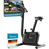
| Model | CardioCross Carbon Champ |
| Dimensions (L x W x H) | Approximately 120 x 60 x 150 cm |
| Device weight | Approximately 45 kg |
| Maximum user weight | 150 kg |
| Power supply | Mains adapter (included) |
| Display | LCD: Time, speed, distance, calories, heart rate, RPM, watts |
| Training programs | Manual, Beginner (4), Advanced (4), Athletic (4), Cardio, Watt |
| Resistance | Magnetic brake, adjustable with + and - buttons |
| Heart rate sensors | Hand grip sensors, chest strap (optional) |
| Special functions | Body fat measurement, recovery test, Bluetooth (iConsole+) |
| Folding | Yes, with locking system |
| Transport wheels | Yes, 2 wheels |
| Warranty | 24 months (parts and labor) |
| Maintenance and cleaning | Clean with a damp cloth, lubricate the lower tubes every 3 months |
| Safety | Automatic shutdown after 4 minutes of inactivity, protected power cable |
Frequently Asked Questions - CardioCross Carbon Champ Skandika
User questions about CardioCross Carbon Champ Skandika
0 question about this device. Answer the ones you know or ask your own.
Ask a new question about this device
Download the instructions for your Exercise bike in PDF format for free! Find your manual CardioCross Carbon Champ - Skandika and take your electronic device back in hand. On this page are published all the documents necessary for the use of your device. CardioCross Carbon Champ by Skandika.
USER MANUAL CardioCross Carbon Champ Skandika
natural_image
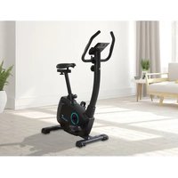
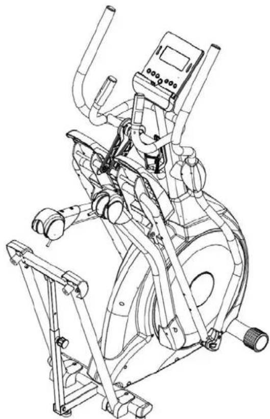
Exterior view of a skandika stationary exercise bike (no signage or text visible on the device itself)GB Assembly instructions and user guide
text_image
Fitness Camping Fitness Bags Fitness Punchout, quality, headwelling and ability to maintain smooth with Flazing and cooking as a design tool for fitness.text_image
QR code image containing encoded data, no visible human-readable textnatural_image
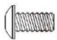
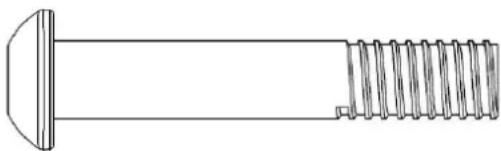
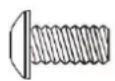
Technical line drawing of a bolt with threaded end and flat head (no text or symbols)97. 3/8" x 2-1/4"
Bolzen (6 Stück)
natural_image
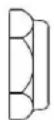
Technical line drawing of a screw with threaded end and flat head (no text or symbols)95. 3/8" × 1-1/2"
Bolzen (1 Stück)
natural_image
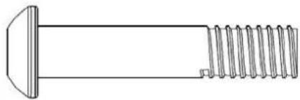
Technical line drawing of a screw with threaded end and flat head (no text or symbols)96. 3/8" × 2"
Bolzen (1 Stück)
114. 5/16" x 7T
Mutter (2 Stück)
115. 3/8" × 7T
Mutter (2 Stück)
123. 3/8" x 19 x1.5T
natural_image
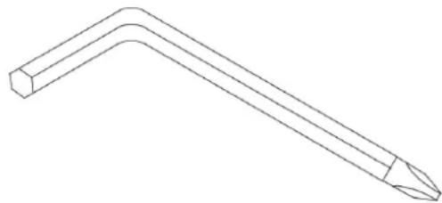
Line drawing of a bent tool with a pointed tip (no text or symbols)135. Kombination M5
natural_image
Simple line drawing of a wrench (no text or symbols)136. 12mm
natural_image
Simple line drawing of a double-ended wrench (no text or symbols)137. 13/14mm
text_image
Technical diagram of a stationary exercise machine with numbered components and labeled partsAUFBAUANLEITUNG
Schritt 2
text_image
Technical diagram of an stationary exercise machine with numbered components and labeled partsAUFBAUANLEITUNG
Schritt 3
text_image
Technical diagram of an stationary exercise machine with numbered components for identification.AUFBAUANLEITUNG
Schritt 4
text_image
Technical diagram of a stationary exercise machine with numbered components and labeled partsnatural_image
Close-up of a hand holding a bottle near a vehicle's seat, no visible text or symbolsTransport
natural_image
Person using a stationary exercise machine with a large wheel and headrest (no visible text or symbols)ZUSAMMENKLAPPEN
Schritt 1
text_image
Technical diagram of an exercise machine with labeled components and motion arrowsSchritt 2
text_image
Technical line drawing of an exercise machine with labeled components and motion indicatorsZUSAMMENKLAPPEN
Schritt 3
text_image
Technical diagram of an exercise machine with labeled components and motion arrowsSchritt 4
natural_image
Line drawing of a person using an exercise bike with adjustable arms and legs (no text or symbols)AUSKLAPPEN
Schritt 1
text_image
Technical diagram of a stationary exercise machine with labeled components and motion arrowsSchritt 2
natural_image
Technical line drawing of a stationary exercise machine with levers and control panel (no text or symbols)AUSKLAPPEN
Schritt 3
text_image
Technical line drawing of an exercise machine with labeled components and motion arrowsDE
Schritt 4
natural_image
Line drawing of an outdoor fitness equipment with levers and control panel (no text or symbols)COMPUTER | BEDIENUNG

text_image
skandika 0:00 P 0:00 0:00 0:00 MANUAL MODE BODY FAT RECOVERY DOWN UP RESET START/ STOPFunktionen
text_image
WATT 120 WATT SETTINGtext_image
SEX = MALE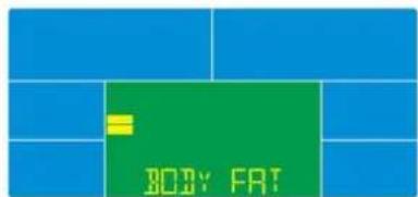
text_image
BODY FAT
text_image
FRT 149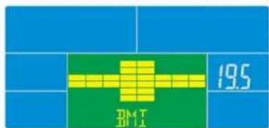
text_image
19.5 D#4 T 2011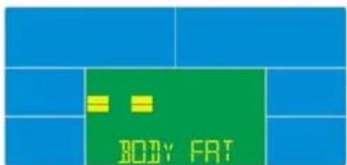
text_image
BODY FAT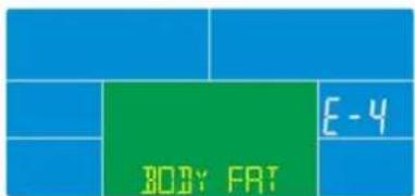
text_image
BODY FAT E-4text_image
iConsole+ iconsole

text_image
iConsole+ iconsole
EXPLOSIONSZEICHNUNG
IMPORTANT SAFETY INFORMATION
ATTENTION!
Use the device only according to its intended purpose as specified in the instruction manual. The warranty will be invalidated if the device is used for purposes other than those for which it is intended. The device has been manufactured for domestic use.
IMPORTANT SAFETY PRECAUTIONS
This exercise machine is built for optimum safety. However, certain precautions apply whenever you operate any exercise equipment. Be sure to read the entire manual before you assemble or operate your machine. In particular, note the following safety precautions:
DANGER – To reduce the risk of electric shock:
Always unplug this appliance from the electrical outlet immediately after using and before cleaning.
WARNING – To reduce the risk of burns, fire, electric shock or injury to persons:
-
Never leave the unit unattended if it is connected to the power supply. Always unplug this appliance from the electrical outlet immediately after using and before changing any parts.
-
Do not cover up the appliance when it is switched on. Never use it under blankets or cushions. There is a risk of fire, electric shock or injury.
-
Children, invalids and disabled persons should not use the machine without a qualified person or physician, who can provide qualified surveillance / assistance.
-
Use the machine only for its intended use as described in this manual. DO NOT use attachments not recommended by the manufacturer.
-
Do not use the appliance if it, or the power cord show signs of damage, if it is not in perfect working order, or if it has been dropped or become damp. In order to prevent hazards, always send the unit in to the service centre.
-
Do not carry, pull or twist the device on the cable or the power supply unit.
-
Keep the power supply unit, cable and appliance well away from heat, hot surfaces, moisture and liquids.
-
Do not block the openings. Never place the device where the openings may be obstructed during operation. Do not cover the device with a blanket or towel etc, during use.
-
Never drop or insert any object into any opening.
-
Do not use outdoors.
-
Never use the unit in rooms in which aerosols (sprays) are being used or where pure oxygen is being administered.
-
Only connect this device to a properly grounded outlet.
-
The device has been manufactured for domestic use.
-
The max. user capacity is 150 kgs.
-
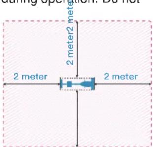
Please only exercise with a minimum clearance area of 2 meters around the device.
text_image
during spoution: Do not 2 meter 2 meter 2 meter 2 meter- To disconnect the unit from the power supply, always pull the plug out of the socket. Do not pull on the cable!
• Do not operate the device on plush or carpet floorings. Damage to the device and to flooring may occur. - BEFORE BEGINNING ANY EXERCISE PROGRAM, CONSULT YOUR PHYSICIAN. THIS IS ESPECIALLY IMPORTANT FOR INDIVIDUALS OVER THE AGE OF 35 OR PERSONS WITH PRE-EXISTING HEALTH PROBLEMS.
- Keep hands away from all moving parts.
- The pulse sensor is not a medical device. Various factors (including the user's movement), may affect the accuracy of the heart rate readings. The pulse sensor is intended only as an exercise aid in determining the heart rate frequency in general.
- Use the machine only for its intended use as described in this manual.
• Always wear appropriate workout clothing when exercising. DO NOT wear robes or other clothing that could become caught in the machine. Running or aerobic shoes are also required when using the machine.
- Failure to follow these instructions may result in injury or in damage to the device.
KEEP THESE INSTRUCTIONS.
CAUTION!! Please be careful when unpacking the carton.
TABLE OF CONTENTS
Table of contents
Important Safety Precautions....26
Hardware Pack Checklist 28
Assembly Instructions....31
Lubrication & Transport 35
Folding & Unfolding 36
Computer Instructions 40
Exploded Diagram 45
Parts List....46
Guarantee Conditions....49
Visit our website for further information
www.skandika.com

text_image
Fitness Camping Fitness Bags Fitness Functional, scientific, technical and wellness – each and Planning of various fitness concepts and effectiveness.WATCH OUR SETUP VIDEO!

text_image
QR code image containing encoded data, no visible human-readable textTo help you with the setup process, we have created a demonstration video which can be viewed on our youtube channel here:
https://youtu.be/6AATmUjw7Do

Check out all of our videos at our youtube channel: https://www.youtube.com/skandika-Europe

text_image
skandika CardioCross Carbon Champ (SF ... YouTubeHARDWARE PACK
Step 1
text_image
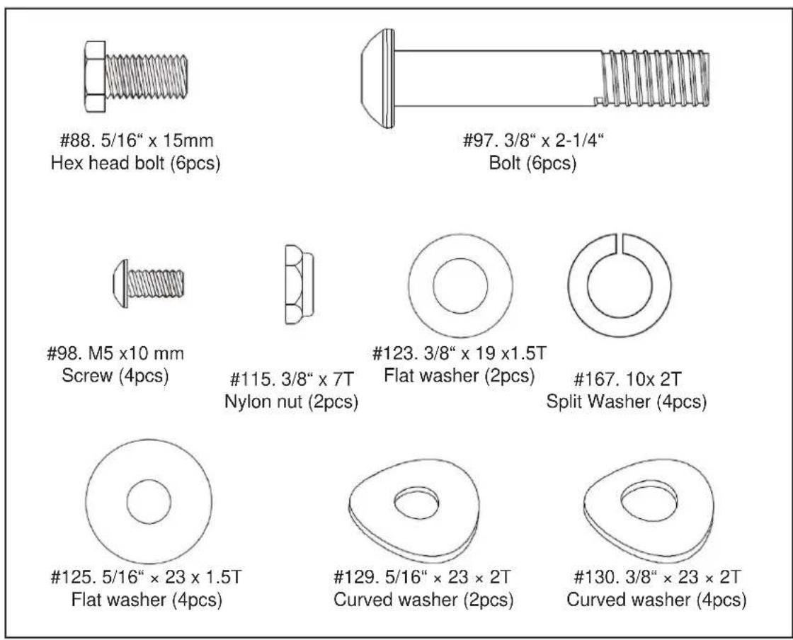
#88. 5/16" x 15mm Hex head bolt (6pcs) #97. 3/8" x 2-1/4" Bolt (6pcs) #98. M5 x10 mm Screw (4pcs) #115. 3/8" x 7T Nylon nut (2pcs) #123. 3/8" x 19 x1.5T Flat washer (2pcs) #167. 10x 2T Split Washer (4pcs) #125. 5/16" x 23 x 1.5T Flat washer (4pcs) #129. 5/16" x 23 x 2T Curved washer (2pcs) #130. 3/8" x 23 x 2T Curved washer (4pcs)Step 2
text_image
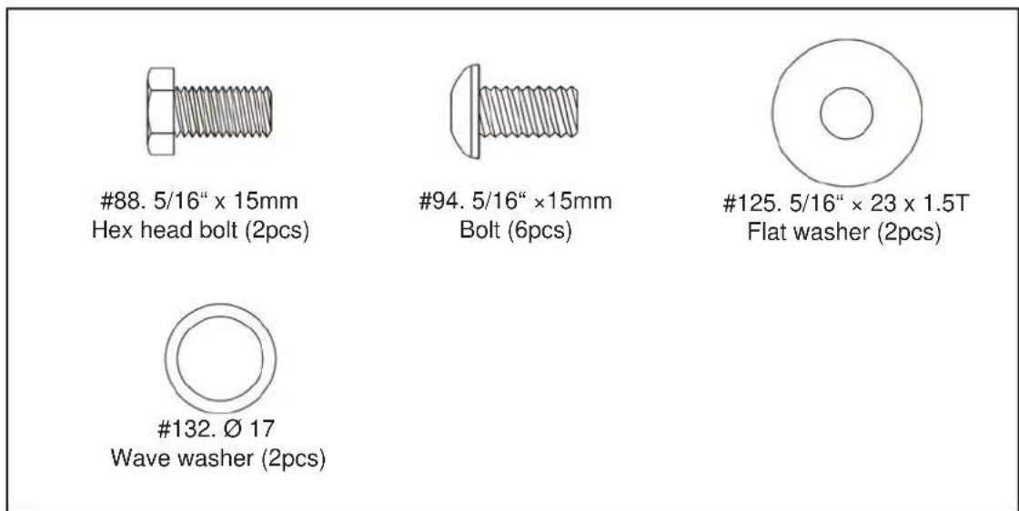
#88. 5/16" x 15mm Hex head bolt (2pcs) #94. 5/16" ×15mm Bolt (6pcs) #125. 5/16" × 23 x 1.5T Flat washer (2pcs) #132. Ø 17 Wave washer (2pcs)Step 3
text_image
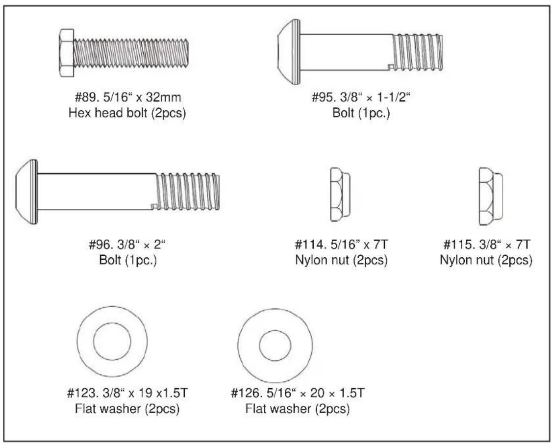
#89. 5/16" x 32mm Hex head bolt (2pcs) #95. 3/8" x 1-1/2" Bolt (1pc.) #96. 3/8" x 2" Bolt (1pc.) #114. 5/16" x 7T Nylon nut (2pcs) #115. 3/8" x 7T Nylon nut (2pcs) #123. 3/8" x 19 x1.5T Flat washer (2pcs) #126. 5/16" x 20 x 1.5T Flat washer (2pcs)Step 4
text_image
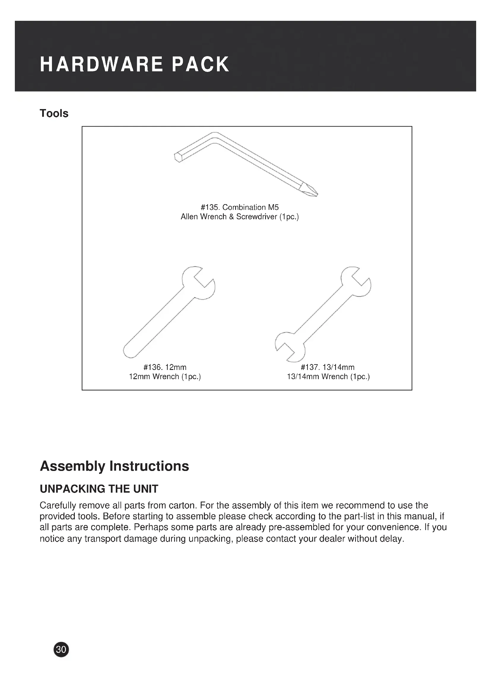
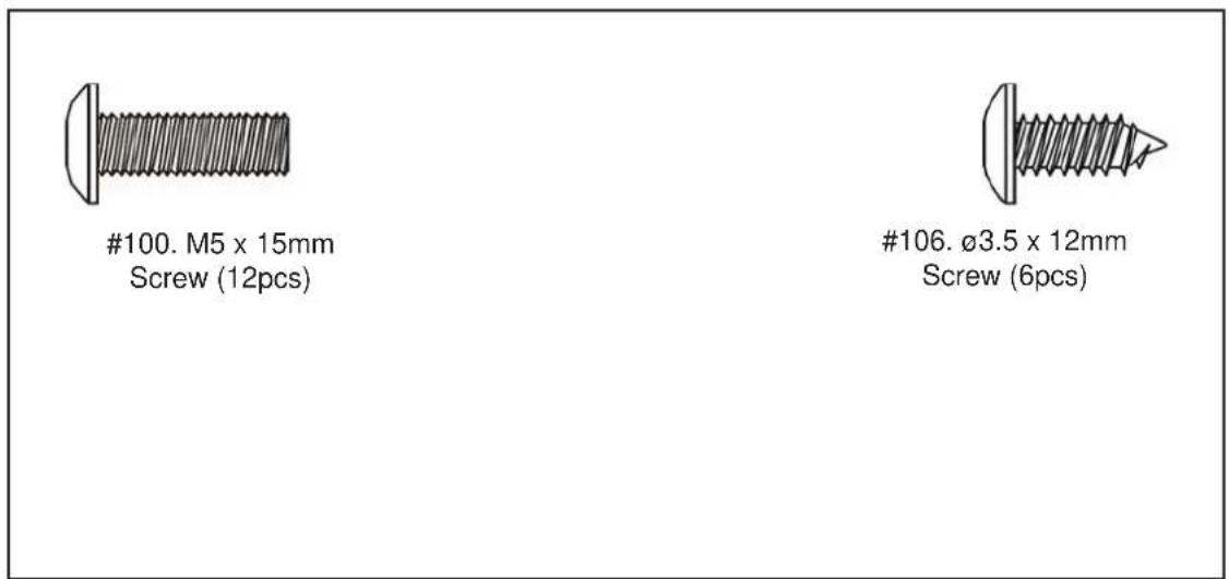
#100. M5 x 15mm Screw (12pcs) #106. Ø3.5 x 12mm Screw (6pcs)Tools
natural_image
Line drawing of a bent tool with a pointed tip (no text or symbols)135. Combination M5
Allen Wrench & Screwdriver (1pc.)
natural_image
Simple line drawing of a wrench (no text or symbols)136. 12mm
12mm Wrench (1pc.)

natural_image
Simple line drawing of a double-ended wrench (no text or symbols)137. 13/14mm
13/14mm Wrench (1pc.)
Assembly Instructions
UNPACKING THE UNIT
Carefully remove all parts from carton. For the assembly of this item we recommend to use the provided tools. Before starting to assemble please check according to the part-list in this manual, if all parts are complete. Perhaps some parts are already pre-assembled for your convenience. If you notice any transport damage during unpacking, please contact your dealer without delay.
ASSEMBLY INSTRUCTIONS
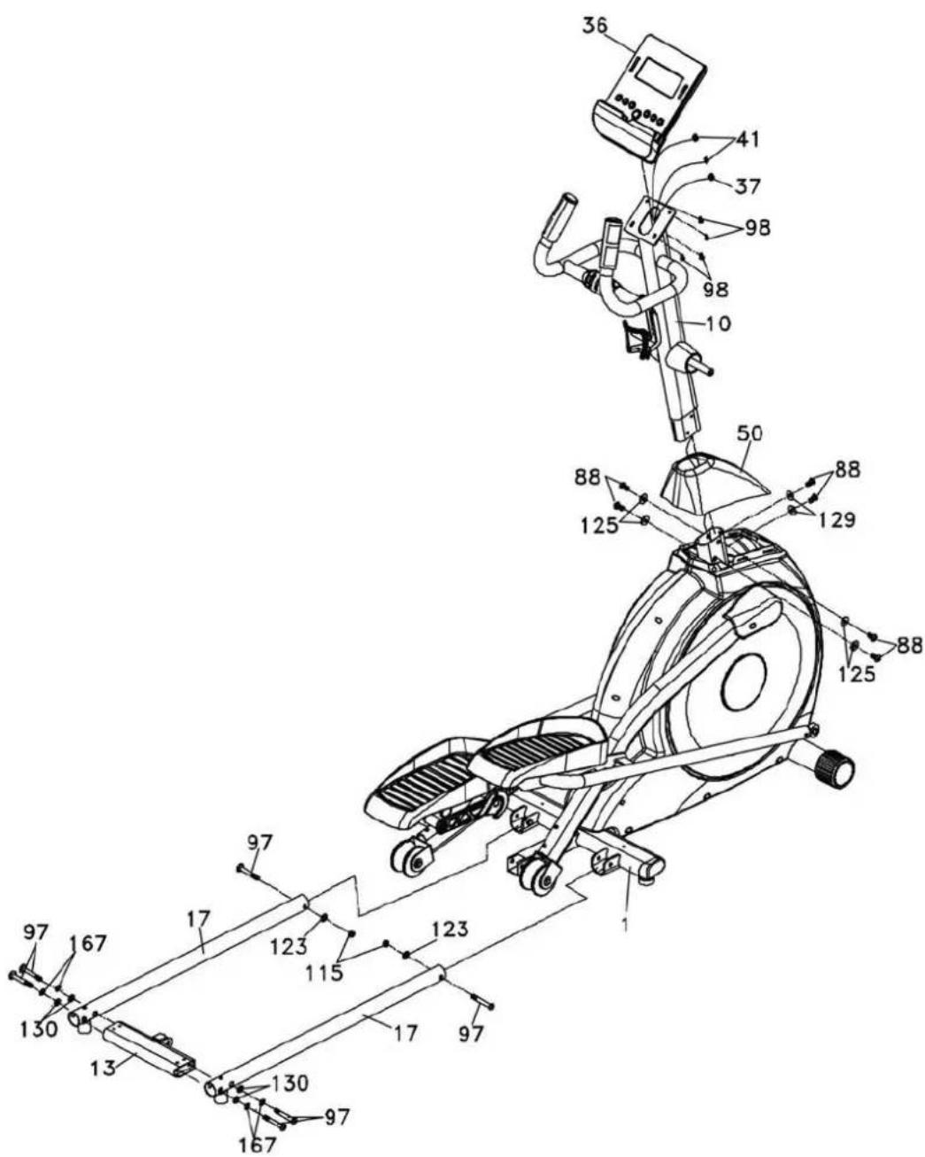
Step 1
Insert front post (10) into main frame (1) through the decorative cover (50), the computer cable (37) needs to be guided through the front post (10). Fix front post (10) to main frame (1) with flat washers (125), bolts (88) and curved washers (129). Slide down the decorative cover (50). Be careful not to squeeze any cables!
Connect computer cable (37) and upper pulse cables (41) to computer (36) accordingly. Attach computer (36) to the top bracket of front post (10) and secure with four screws (98).
Fix bottom tubes (17) on main frame (1) with 2 bolts (97), 2 flat washers (123) and 2 nuts (115).
Fix connecting bar (13) on bottom tubes (17) with 4 bolts (97), 4 split washers (167) and 4 curved washers (130).
text_image
Technical diagram of a stationary exercise machine with numbered components and labeled partsASSEMBLY INSTRUCTIONS
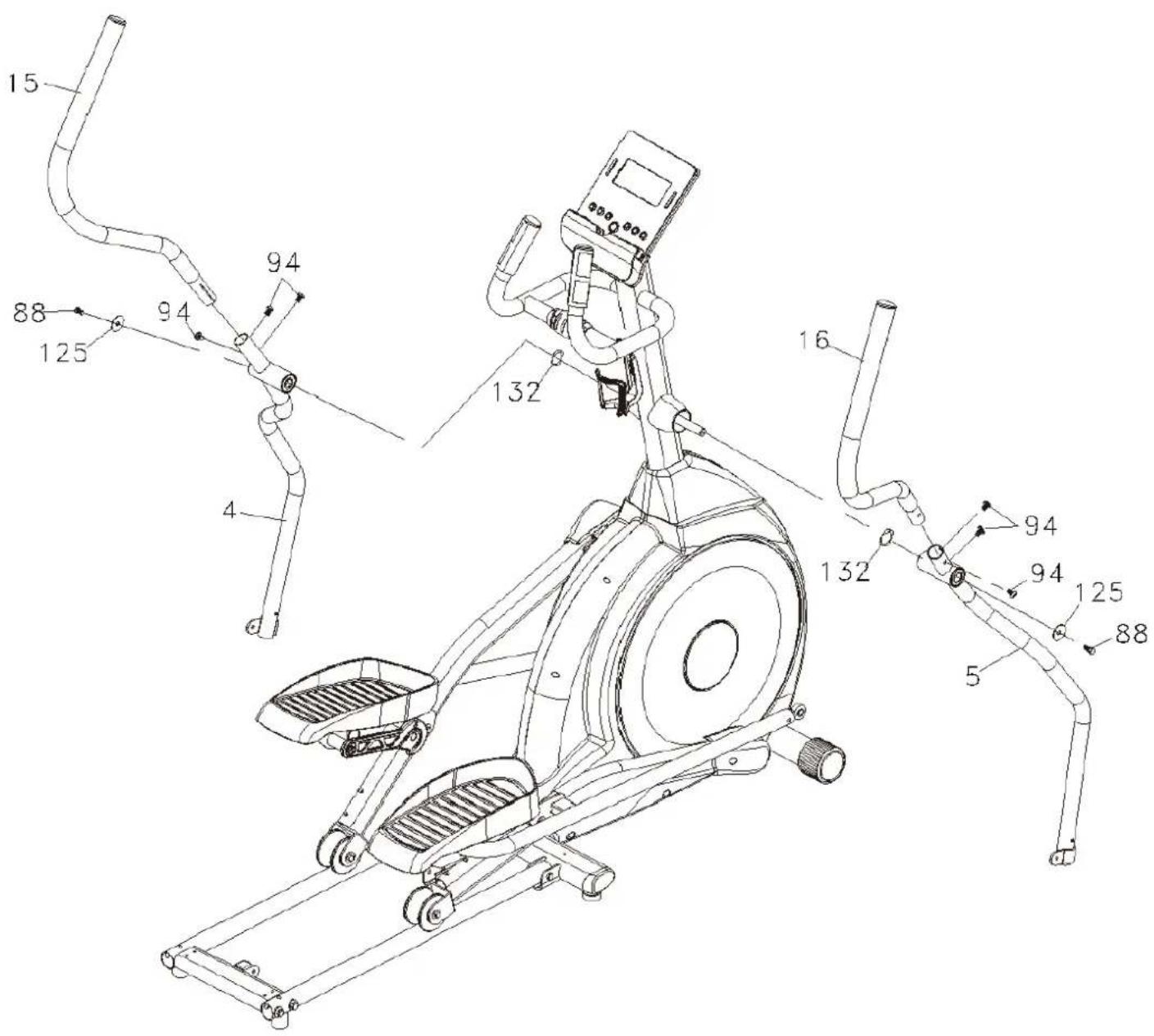
Step 2
Fix left & right bottom handlebar tubes (4&5) on front post (10) with wave washers (132), bolts (88) and flat washers (125). Fix left & right swing arms (15&16) on bottom handlebar tubes (4&5) with bolts (94) as shown in the drawing.
text_image
Technical diagram of an exercise machine with numbered components and labeled partsASSEMBLY INSTRUCTIONS
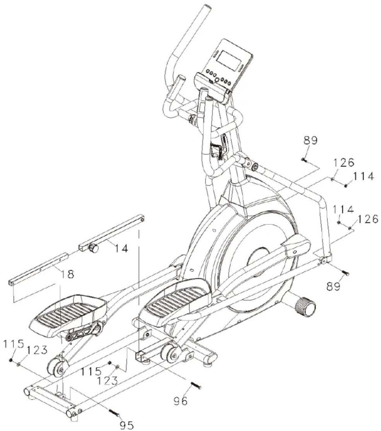
Step 3
Connect left & right bottom handlebar tubes (4&5) to pedal arms with bolts (89), flat washers (126) and nuts (114). Fix outer slide (14) on main frame (1) with bolt (96), flat washer (123) and nut (115) as shown in the drawing. Afterwards, fix inner slide (18) on connecting bar (13) with bolt (95), flat washer (123) and nut (115).
text_image
Technical diagram of an outdoor fitness machine with numbered components and labeled partsASSEMBLY INSTRUCTIONS
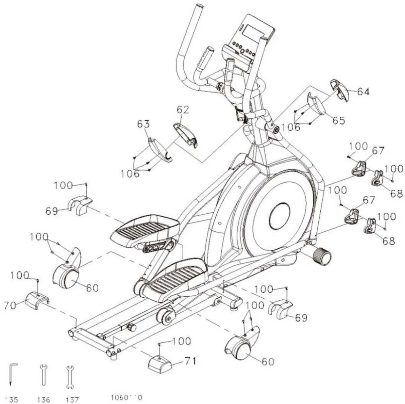
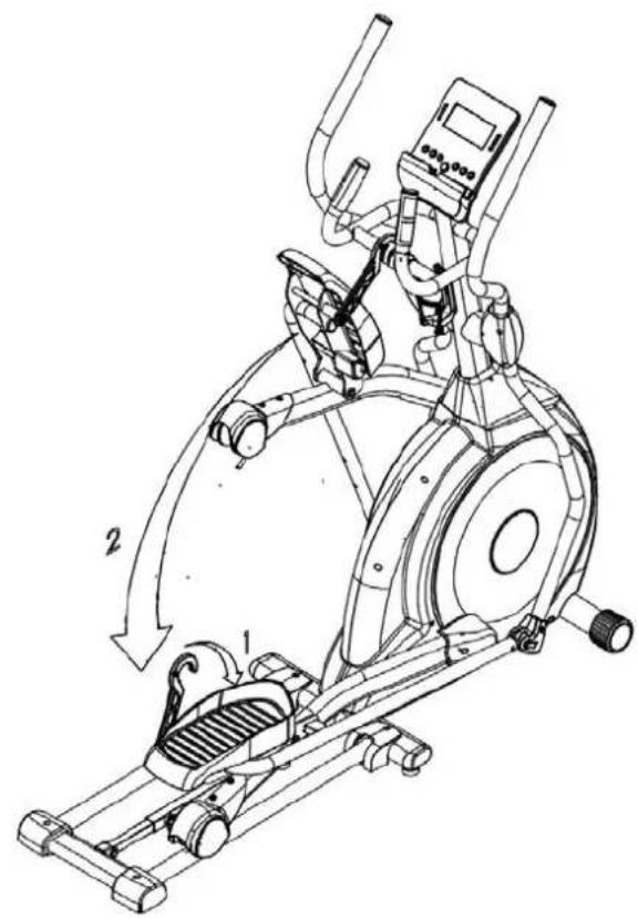
Step 4
Fix left cover (67) and right cover (68) on left & right bottom handlebar tubes (4&5) with totally 4 screws (100). The covers for wheels (60) need to be fixed on left & right pedal arms (2&3) with 4 screws (100) as well. Mount the front and rear handlebar covers (62/63/64/65) onto the left & right bottom handlebar tubes (4&5) as shown in the drawing with totally 6 screws (106).
Fix the covers (69) on each side of main frame (1) with 2 screws (100). The rear stabilizer covers (70&71) need to fixed with each one screw (100) on the connecting bar (13).
text_image
Technical diagram of a stationary exercise machine with numbered components and exploded view detailsLUBRICATION & TRANSPORT
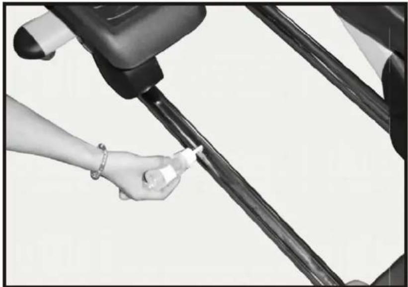
Lubrication
-
Put some lubricant (2 ml) onto the middle part of bottom tubes (see picture). We recommend lubricating every 3 months.
-
If the tubes should be very dry or abnormal noise occurs, lubrication needs to be done.
natural_image
Close-up of a hand holding a bottle near a vehicle's seatbelt (no visible text or symbols)Transport
Carefully move the item with the transportation rolls to the desired place. Do not roll over uneven ground!
natural_image
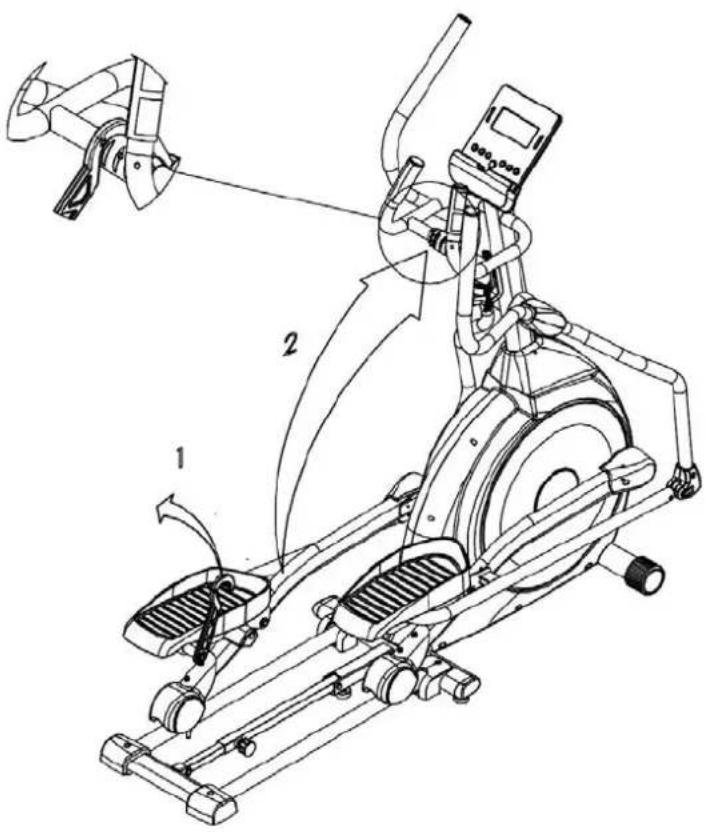
Person using a stationary exercise machine with a large wheel and headrest (no visible text or symbols)FOLDING
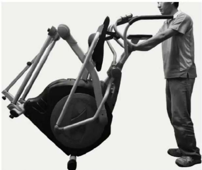
Step 1
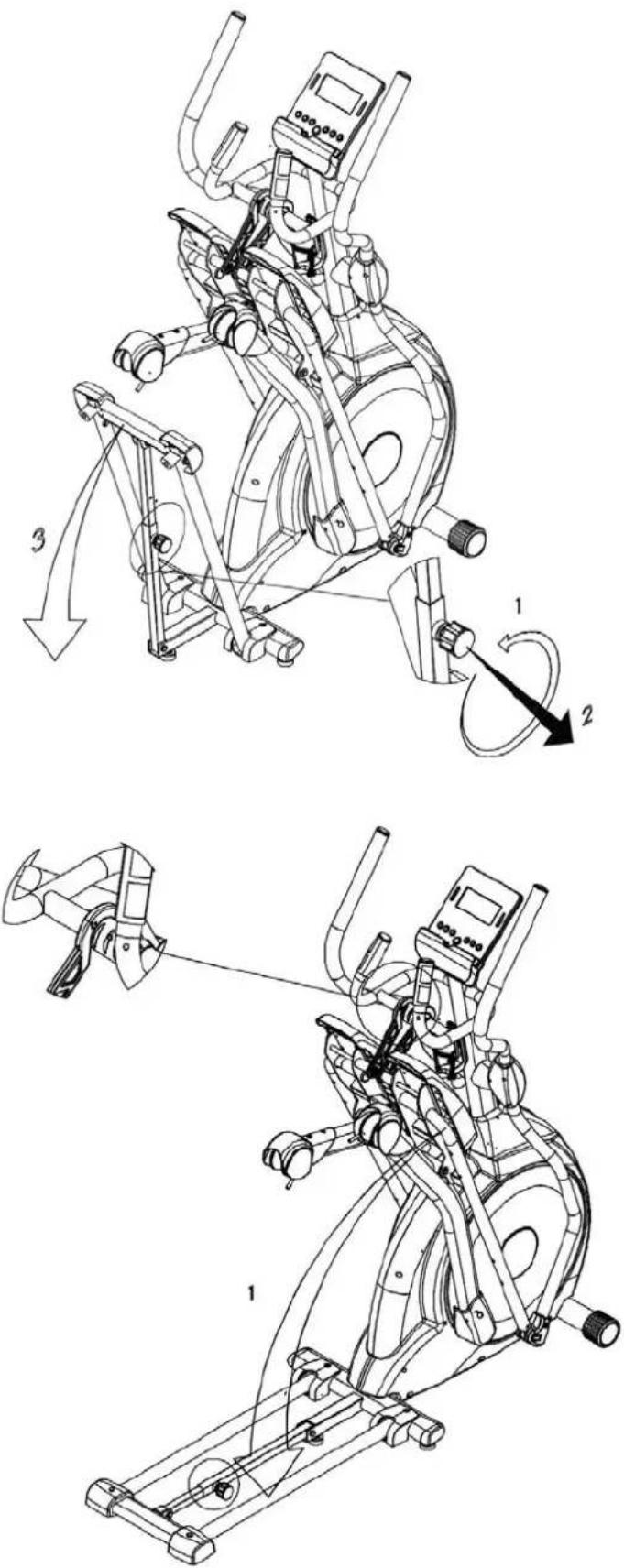
Before folding the device, please switch off the item. Pull up the hook, hold the wheel cover with one hand and hang the hook onto the notch of hanging cap with the other hand as shown in the drawing.
text_image
Technical diagram of an exercise machine with labeled components and motion arrowsStep 2
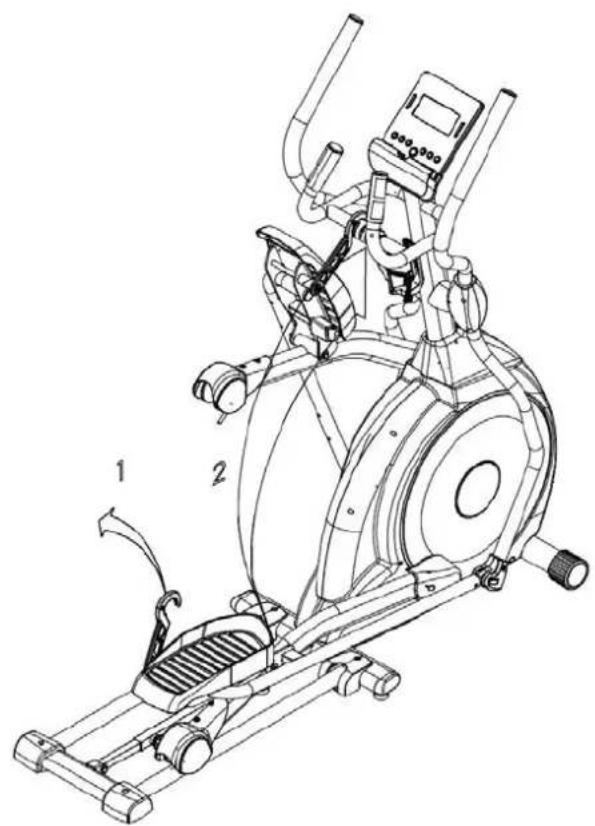
Repeat for the other side.
text_image
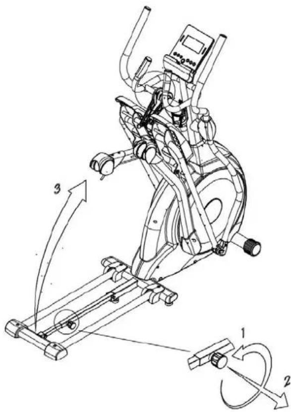
Technical line drawing of an exercise machine with labeled components and motion indicatorsStep 3
Turn the locking knob counterclockwise and pull to unlock. Fold up the device and lock it up with the knob by turning it clockwise until the folded device is secured.
text_image
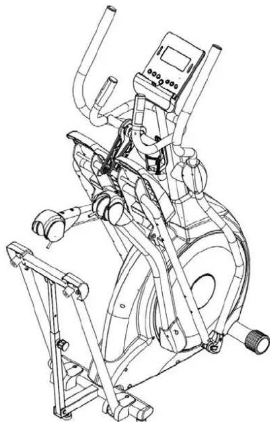
Technical diagram of an exercise machine with labeled components and motion arrows indicating rotational movement.Step 4
Folded position.
natural_image
Line drawing of a stationary exercise machine with adjustable arms and legs (no text or symbols)UNFOLDING
Step 1
Turn the locking knob counterclockwise and pull to unlock. Unfold the device and lock it in unfolded position with the by turning it clockwise.
Step 2
Pull up the hook, hold the wheel cover with one hand and release the hook from the notch of hanging cap with the other hand as shown in the drawing. Put down the wheel.
UNFOLDING
Step 3
Repeat for the other side.
text_image
Technical line drawing of an exercise machine with labeled components and motion arrowsStep 4
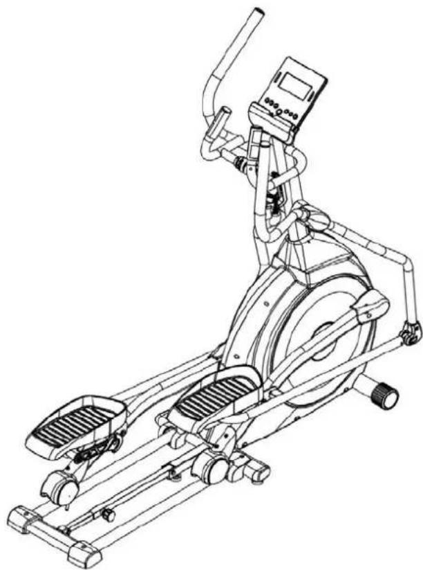
Unfolded position.
natural_image
Line drawing of an outdoor fitness equipment with levers and control panel (no text or symbols)COMPUTER INSTRUCTIONS

text_image
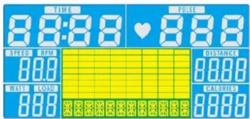
skandika 0:00 P 0:00 0:00 0:00 MANUAL MODE BODY FAT RECOVERY DOWN UP RESET START/ STOPFunctions
| TIME Computer shows actual exercise time (max. 99:59 Min.). | |
| SPEED The computer shows the current speed in the display (max. 99,9 km/h) | |
| DISTANCE The workout distance is displayed here (max. 99,99 km) | |
| CALORIES The currently burned calories are displayed here (max.9999 kcal) | |
| PULSE | The computer is showing the user's heart rate in beats per minute. For a correct display please ensure that you fully grasp the hand sensors. It may last up to 2 minutes before the pulse frequency will be measured correctly. |
| RPM Displays the rounds per minute (max. 999 rpm) | |
| WATTS Computer shows the actual watt value (max. 350 Watt) | |
| MANUAL Manual Mode | |
| BEGINNER Beginner program mode (4 programs) | |
| ADVANCE Advance program mode (4 programs) | |
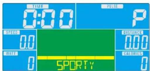
| SPORTY Expert program mode (4 programs) | |
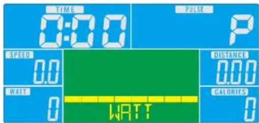
| WATT PROGRAM Watt-controlled training mode. | |
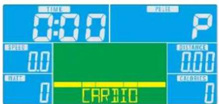
| CARDIO Automatically controlled training depending on your pulse frequency. | |
COMPUTER INSTRUCTIONS
Button functions
| Up | Press this button to increase the resistance during exercise or to increase a setting value. |
| Down | Press this button to decrease the resistance during exercise or to decrease a setting value. |
| Mode Press this | button to confirm any input or selection. |
| Reset | Press and hold button for min. 2 seconds to reset all data.Go back to main menu. |
| Start/ Stop Start | or Stop exercise. |
| Recovery Press | this button to start the heart recovery measurement. |
| Body fat Startet | eine Körperfettmessung. |
COMPUTER | USE
This computer has an automatic on/off function so that it switches on when the pedals move or when any button is pressed, and turns into stand-by mode automatically if no signal has been received for approx. 4 minutes. The computer gets its power supply by the included adaptor. The adaptor will be connected to a normal mains plug (European standard, please check the specifications resp. please use a fitting mains adaptor for your power system).
text_image
TIME 8:8:8 PULSE SPEED RPM 80.0 DISTANCE 80.00 WATI LOAD 800 CALORIES 8000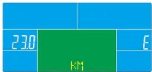
text_image
230 KM EWORKOUT SELECTION
Press UP and DOWN to select workout mode:
Manual → Beginner → Advance → Sporty → Cardio → Watt
Manual Mode
In manual mode you can adjust the load manually.
After selecting „Manual“ (confirm with „MODE“-button) you are in manual mode. Start exercise by pressing “START/STOP”. You may change the tension level at any time during exercise with “UP” and “DOWN”. You may also input target values for the following function values:
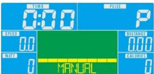
text_image
TIME 0:00 PULSE P SPEED 0.0 WATT 0 DISTANCE 0.00 CALORIES 0 MANUALa. TIME, b. DISTANCE, c. CALORIE, d. PULSE
To input a target value, do not press "START/STOP" after selecting mode, but instead use "UP", "DOWN" and "MODE" to input the target values. After your input, press "START/STOP". To pause exercise, press the „START/STOP“-button at any time. If you press the Reset-button (only possible during pause mode), you may return to main menu.
COMPUTER INSTRUCTIONS
Beginner Mode
In beginner mode you can adjust the load manually and you may preset TIME value. After your input, press "START/STOP". To pause exercise, press the „START/STOP“-button at any time. If you press the Reset-button (only possible during pause mode), you may return to main menu.
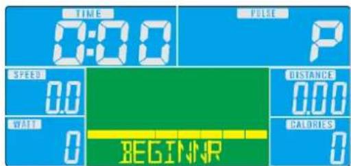
text_image
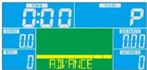
TIME 0:00 PULSE P SPEED 0.0 DISTANCE 0.00 WAIT 0 CALORIES 0 BEGINNRAdvance Mode
In advance mode you can adjust the load manually and you may preset TIME value. After your input, press "START/STOP". To pause exercise, press the „START/STOP“-button at any time. If you press the Reset-button (only possible during pause mode), you may return to main menu.
In sporty mode you can adjust the load manually and you may preset TIME value. After your input, press "START/STOP". To pause exercise, press the „START/STOP“-button at any time. If you press the Reset-button (only possible during pause mode), you may return to main menu.
text_image
TIME 0:00 PULSE P SPEED 0.0 DISTANCE 0.00 WATT 0 CALORIES 0 SPORTYCardio Mode
You can do an automatically steered training depending on your pulse frequency. After selecting this mode and pressing MODE you are in heart frequency controlled modus. Use the „UP/DOWN“-buttons to select your age (default value = 25). Afterwards, please select the target pulse (55%, 75%, 90% of the maximum pulse and direct input of the target pulse).
It is also possible to enter a target time during the program training. Use the „UP/DOWN“-buttons and “MODE” to enter a target time. Start exercise by pressing START/STOP. To pause exercise, press the „START/STOP“-button at any time. If you press the Reset-button (only possible during pause mode), you may return to main menu.
text_image
TIME 0:00 PULSE P SPEED 0.0 DISTANCE 0.00 HATR 0 CALORIES CARTO 0
text_image
PAGE : 25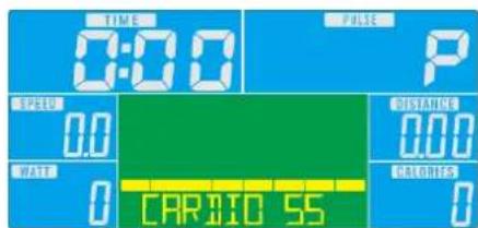
text_image
TIME 0:00 PULSE P SPEED 0.0 WATR 0 CARBIO 55 DISTANCE 0.00 CALORIES 0COMPUTER INSTRUCTIONS
WATT Mode
This is the watt-controlled mode. If you preset a watt value, it is not possible to change the tension during exercise with "UP" and "DOWN" as usual because the computer will control the intensity automatically according to the target value entered. Preset a watt value with the "UP" and "DOWN" buttons ("MODE" for confirmation). It is also possible to enter a target time during the program training. Use the „UP/DOWN“-buttons and "MODE" to enter a target time. Start exercise by pressing START/STOP. To pause exercise, press the „START/STOP“-button at any time. If you press the Reset-button (only possible during pause mode), you may return to main menu.
text_image
TIME 0:00 PULSE P SPEED 0.0 WATT 0 DISTANCE 0.00 CALORIES 0 WATT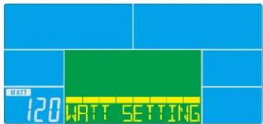
text_image
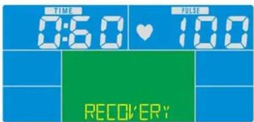
WATT 120 WATT SETTINGRecovery
With this special function, you can check your hearts recovery rate after a training session. This is a very important indication for the physical condition of your body. Try to improve your recovery rate with regular training sessions. The aim is, to calm down to a normal pulse frequency (frequency, when you are not in motion) as quickly as possible. To check your recovery rate, you need to keep your hands onto the hand pulse-sensors after your exercise. Now press the button “RECOVERY”. The computer will start to countdown 60 seconds. During this period the computer will constantly measure your heart rate through the hand sensors. After this minute, your recovery rate will be displayed on the display. The range is F1.0 to F6.0, whereby F1.0 is very good and F6.0 is insufficient. Improve your value by intense and regular training! Press the button “RECOVERY” once again to return to main menu.
| 1.0 outstanding | |
| 1.0 < F < 2.0 excellent | |
| 2.0 < F < 2.9 good | |
| 3.0 < F < 3.9 fair | |
| 4.0 < F < 5.9 below average | |
| 6.0 poor |
text_image
TIME 0:50 ♥ 100 RECOVERY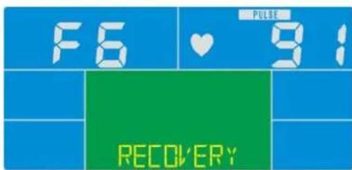
text_image
F6 ♥ 9: RECOVERYCOMPUTER INSTRUCTIONS
Body Fat
- Press this button to start the body fat measurement (works only in STOP mode).
- Enter the values for GENDER, HEIGHT, WEIGHT with "UP", "DOWN" and "MODE".
- Grasp the sensors on both sides fully. The measurement will take about 8 seconds. During measuring you see “=” “==” on the display.
- After the measurement has ended the computer will display the results: BMI, body fat percentage and a symbol will be shown on the display.

text_image
SEX = MALE
text_image
FRT 149
text_image
BODY FAT
text_image
BODY FAT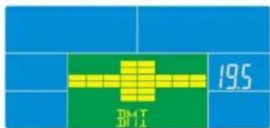
text_image
19.5 Dk4 T 2011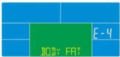
text_image
BODY FAT E-4Error messages
- if the display shows“==”“==”, the contact to the handpulse sensors was not sufficiently for a measurement. The reason for this can be that you have not grasped the two sensors correctly. Start a new measurement with correctly placed hands!
- if "E1" appears, no pulse was detected.
- if "E4" appears, bodyfat and / or BMI value is below 5 or above 50
NOTES
- If computer shows any unusual behavior, disconnect from mains and retry after some minutes.
- if the measured heart rate is below 30 or over 230, "P" will be displayed instead of the heart symbol.
iConsole+ APP
Turn on Bluetooth on phone / tablet device, search for computer device and press connect.
Start iconsole+ app on phone / tablet, and press connect to start workout with phone / tablet. (password: 0000).
NOTE
The computer will power off when console is successfully connected to phone/tablet via Bluetooth.

text_image
iConsole+ iconsole

text_image
iConsole+ iconsole®
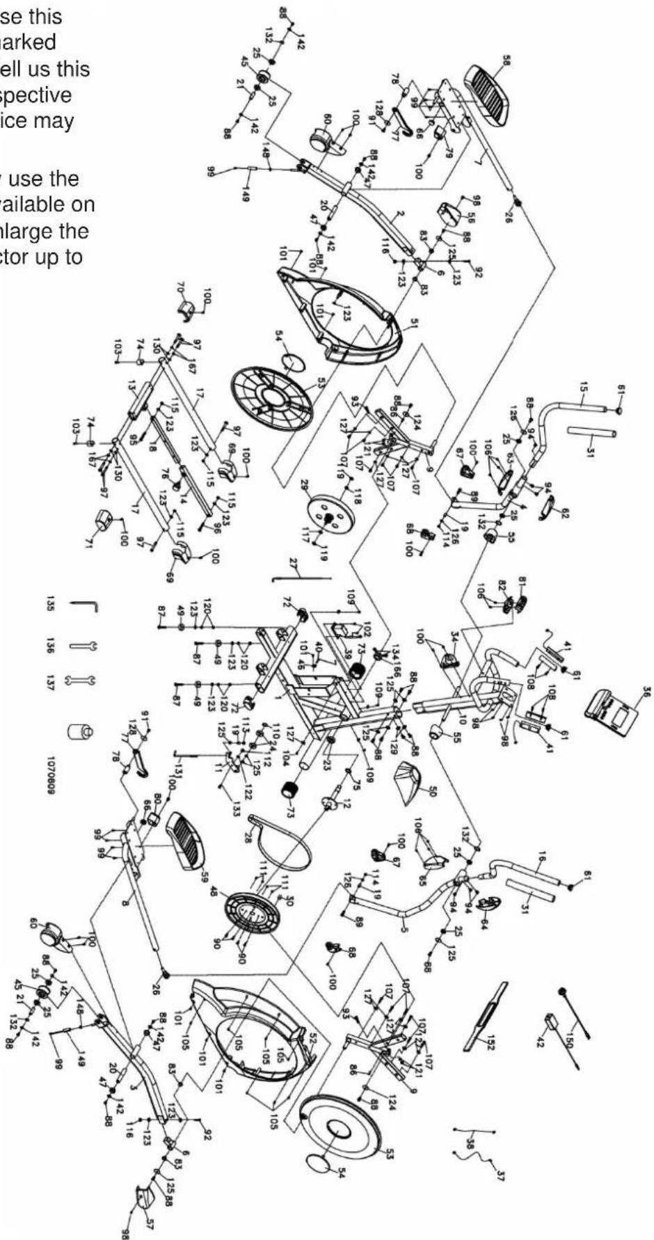
EXPLODED DIAGRAM
In case of mechanical problems use this explosion drawing. All parts are marked with a specific part number in it. Tell us this number in order to replace the respective part (within warranty time this service may be free of charge).
If necessary, you may additionally use the free user manual in pdf-format, available on www.skandika.com. You may enlarge the explosion drawing there with a factor up to 500 %.
text_image
Technical schematic diagram of a mechanical assembly with numbered components and Chinese explanatory text on the left.PARTS LIST
| Part # | Description Qty Part # Description Qty | ||||
| 1 Main frame 1 29 Flywheel 1 | |||||
| 2 Pedal arm (L) 1 30 Magnet 1 | |||||
| 3 Pedal arm (R) 1 31 Handgrip foam | |||||
| 4 Bottom handle bar tube (L) 1 34 Drinking bottle holder | 1 | ||||
| 5 Bottom handle bar tube (R 1 36 Computer 1 | |||||
| 6 Bushing housing 2 37 1100mm_Computer cable | 1 | ||||
| 7 Connecting arm (L) | 1 38 600 mm_DC Power cord 1 | ||||
| 8 Connecting arm (R) | 1 39 Gear motor | 1 | |||
| 9 Cross bar | 2 40 250 mm_Sensor w/cable 1 | ||||
| 10 Front post | 1 41 | 850mm_Upper pulse cable assembly | 2 | ||
| 11 | Idler wheel assembly | 1 | 42 | Power adaptor | 1 |
| 12 Crank axle | 1 45 Slide wheel , Urethane 2 | ||||
| 13 Connecting bar | 1 46 Sensor rack | 1 | |||
| 14 Outer slide | 1 47 | ∅31 × ∅25.5 × ∅19 × 16+3T_Bushing | 4 | ||
| 15 Swing arm (L) 1 48 Drive pulley | 1 | ||||
| 16 Swing arm (R) | 1 49 Rubber foot | 3 | |||
| 17 Bottom tube | 2 50 Decorative cover 1 | ||||
| 18 Inner slide | 1 51 Side case (L) 1 | ||||
| 19 Rod end sleeve | 3 52 Side case (R) 1 | ||||
| 20 Axle for pedal | 2 53 Round disk 2 | ||||
| 21 Axle for slide wheel | 2 54 Round disk cover 2 | ||||
| 55 Cover for swing arm axle | 2 | ||||
| 23 6005_Bearing 1 56 Pedal arm cover (L) | 1 | ||||
| 24 6203_Bearing 2 57 Pedal arm cover (R) | 1 | ||||
| 25 6003_Bearing 8 58 Pedal (L) | 1 | ||||
| 26 Rod end bearing 2 59 Pedal (R) | 1 | ||||
| 27 Steel cable | 1 60 Wheel cover 2 | ||||
| 28 Drive belt | 1 61 Button head plug 4 | ||||
| Part # | Description Qty Part # Description Qty | ||||
| 62 | Front handle bar cover (L) 1 92 3/8" × 2-1/4" _Bolt 2 | ||||
| 63 | Rear handle bar cover (L) 1 93 M8 | × 40mm_ Bolt 2 | |||
| 64 | Front handle bar cover (R) 1 94 5/1 | 6" × 15m m_Bolt 6 | |||
| 65 | Rear handle bar cover (R) 1 95 3/8" × 1-1/2" _Bolt 1 | ||||
| 66 | Round cap 2 96 3/8" × 2" _Bolt 1 | ||||
| 67 | Left cover 2 97 3/8" × 2-1/4" _Bolt 6 | ||||
| 68 | Right cover 2 98 M5 × 10mm_Screw 6 | ||||
| 69 | Middle stabilizer cover 2 99 M5 × 10mm_Screw 10 | ||||
| 70 | Rear stabilizer cover (L) | 1 | 100 | M5 × 15mm_Screw | 16 |
| 71 | Rear stabilizer cover (R) | 1 | 101 | 5 × 16mm_Tapping screw | 7 |
| 72 | Oval end cap | 2 | 102 | 5 × 19mm_Tapping screw | 2 |
| 73 | Transportation wheel | 2 | 103 | 5 × 25mm_Tapping screw | 2 |
| 74 | Rubber foot | 2 | 104 4.8 | × 38mm_Screw 1 | |
| 75 | Spacer bushing | 1 | 105 | 3.5 × 16mm_Screw | 7 |
| 76 | Locking knob | 1 | 106 | ∅3.5 × 12mm_Screw | 8 |
| 77 | Hook | 2 | 107 | 5 × 16mm_Tapping screw | 12 |
| 78 | Hook sleeve | 2 | 108 | ∅3 × 20mm_Tapping screw | 4 |
| 79 | Hook fixing block (L) | 1 | 109 | 3.5 × 16mm_Tapping screw | 3 |
| 80 | Hook fixing block (R) | 1 | 110 | ∅17_C-Ring | 1 |
| 81 | Hook hanging cap (Top) | 1 | 111 | 1/4" × 8T_Nylon nut | 4 |
| 82 | Hook hanging cap (Bottom) | 1 | 112 | M8 × 7T_Nylon nut | 1 |
| 83 | WFM-1719-12_Bushing | 4 | 113 | M8 × 9T_Nylon nut | 1 |
| 86 | 25 × 7 × 7mm_Woodruff key | 2 | 114 | 5/16" × 7T_Nylon nut | 2 |
| 87 | 3/8" × 2" Flat bolt | 3 | 115 | 3/8" × 7T_Nylon nut | 4 |
| 88 | 5/16" × 15mm_Hex head bolt | 20 | 116 | 3/8" × 11T_Nylon nut | 2 |
| 89 | 5/16" × 32mm_Hex head bolt | 2 | 117 | 3/8" -UNF26 × 4T_nut | 1 |
| 90 | 1/4" × 3/4" _Hex head bolt | 4 | 118 | 3/8" -UNF26 × 6T_nut | 1 |
| 91 | M6 × 15mm_Hex head bolt | 2 | 119 | 3/8" -UNF26 × 11T_nut | 2 |
PARTS LIST
| Part # | Description Qty | |
| 120 3/8" × 7T_nut 6 | ||
| 121 M8 × 6.3T_nut 4 | ||
| 122 ∅17 × ∅23.5 × 1T_Flat washer 2 | ||
| 123 3/8" × 19 × 1.5T_Flat washer 12 | ||
| 124 5/16" × 35 × 1.5T_Flat washer 2 | ||
| 125 5/16" × 23 × 1.5T_Flat washer 10 | ||
| 126 5/16" × 20 × 1.5T_Flat washer 2 | ||
| 127 1/4" × 19mm_Flat washer 13 | ||
| 128 ∅6.5 × ∅25 × 1.5T_Flat washer 2 | ||
| 129 5/16" × 23 × 2T_Curved washer 2 | ||
| 130 3/8" × 23 × 2T_Curved washer 4 | ||
| 131 M8 × 170mm_J Bolt 1 | ||
| 132 ∅17 × 0.3T_Wave washer 4 | ||
| 133 M8 × 20mm_Carriage bolt 1 | ||
| 135 Combination M5 Allen Wrench & Screw Driver | 1 | |
| 136 12mm_Wrench | 1 | |
| 137 13/14mm_Wrench | 1 | |
| 142 5/16" × 23 × 3.0T_Flat washer 4 | ||
| 148 E-Clip | 8 | |
| 149 ∅15 × ∅8.5 × 50L_Sleeve 2 | ||
| 150 Transformer power cord | 1 | |
| 152 Chest strap (optional) | 1 | |
| 166 6005-2RS_Bearing | 1 | |
| 167 3/8" × 2T_Split Washer | 4 | |
| 257 Spacer Bushing | 2 | |
GUARANTEE CONDITIONS
For our devices we provide a warranty as defined below.
- In accordance with the following conditions (numbers 2-5) we repair defect or damage to the device free of charge, if the cause is a manufacturing defect. Therefore, these defects / damages need to be reported to us without delay after appearance and within the warranty period of 24 months after delivery to the end user. The warranty does not cover parts, which easily break (e.g. glass or plastic). The warranty does not cover slight deviations of the product, which are insignificant for usability and value of the device and damage caused by chemical or electrochemical effects and damages caused by penetration of water or generally force majeure damage.
- The warranty achievement is the replacement or repair of defective parts, depending on our decision. The cost of material and labor will be borne by us. Repairs at customer site cannot be demanded. The proof of purchase along with the date of purchase and / or delivery is required. Replaced parts become our property.
- The warranty is void if repairs or adjustments are made, which are not authorized by us or if our devices are equipped with additional parts or accessories that are not adapted to our devices. Furthermore, the warranty is void if the device is damaged or destroyed by force majeure or due to environmental influences and in case of improper handling / maintenance (e.g. due to non-observance of the instruction manual) or mechanical damages. The customer service may authorize you to replace or repair defective parts after telephone consultation. In this case, the warranty is not void.
- Warranty services do not extend the warranty period nor do they initiate a new warranty period.
- Further demands, especially claims for damages which occurred outside the device, are excluded as long as a liability is not obligatory legal.
- Our warranty terms - which cover the requirements and scope of our warranty conditions - do not affect the contractual warranty obligations of the seller.
- Parts of wear and tear are not included in the warranty.
- The warranty is void if not used properly or if used in gyms, rehabilitation centers and hotels. Even if most of our units are suitable for a professional use, this requires a separate agreement.
Environmental protection
At the end of its life cycle, this product must not be disposed of with household waste but must be taken to a collection unit for the recycling of electric and electronic equipment. The symbol on the product, the instructions for use or the packaging express mention of this. The basic materials can be recycled as specified on the labelling.
When recycling the materials and finding other utilisation for used equipment, you are making a significant contribution towards protecting our environment. Ask at your council about the respective local disposal sites.
For service, accessories and spare parts, please contact: service@skandika.com
Service centre: MAX Trader GmbH, Wilhelm-Beckmann-Straße 19, 45307 Essen, Germany
INFORMATION DESÉCURITÉ IMPORTANTES
ATTENTION!
Boulon hexagonal (6pcs)
natural_image
Technical line drawing of a bolt with threaded end and flat head (no text or symbols)97. 3/8" x 2-1/4"
Boulon (6pcs)
98. M5 x10 mm
Vis (4pcs)
115. 3/8" x 7T
Rondelle fendue (4pcs)
123. 3/8" x 19 x1.5T
Rondelle plate (2pcs)
125. 5/16" × 23 × 1.5T
Rondelle plate (4pcs)
129. 5/16" × 23 × 2T
text_image
#100. M5 x 15mm Vis (12pcs) #106. Ø3.5 x 12mm Vis (6pcs)LISTE DE CONTRÔLE DU SAC DE PETITES PIÈCES
Outils

natural_image
Line drawing of a bent tool with a pointed tip (no text or symbols)135. Combinaison M5
Clé Allen & Tournevis (1pc.)
natural_image
Simple line drawing of a wrench (no text or symbols)136. 12mm
Clé (1pc.)
natural_image
Simple line drawing of a double-ended wrench (no text or symbols)137. 13/14mm
Clé (1pc.)
INSTRUCTIONS DE MONTAGE
DÉBALLAGE DE L'UNITÉ
text_image
Technical diagram of a stationary exercise machine with numbered components and labeled partsINSTRUCTIONS DE MONTAGE
Étape 2
text_image
Technical diagram of an exercise machine with numbered components and labeled partsINSTRUCTIONS DE MONTAGE
Étape 3
text_image
Technical diagram of an stationary exercise machine with numbered components for identification.INSTRUCTIONS DE MONTAGE
Étape 4
text_image
Technical diagram of an stationary exercise machine with numbered components and safety featuresGRAISSAGE & TRANSPORT
Schmierung
natural_image
Close-up of a hand holding a bottle next to a car seatbelt, no visible text or symbols
Transport
natural_image
Person using a stationary exercise machine with arms extended, no visible text or symbolsPLIAGE
Étape 1
text_image
Technical diagram of an exercise machine with labeled components and motion arrows indicating rotation or movement.Étape 2
text_image
Technical line drawing of an exercise machine with labeled components and motion indicatorsÉtape 3
text_image
Technical diagram of an exercise machine with labeled components and motion arrows indicating rotational movement.Étape 4
Position pliée.
natural_image
Line drawing of a person using an exercise bike with adjustable arms and legs (no text or symbols)DÉPLIAGE
Étape 1
text_image
Technical line drawing of an stationary exercise machine with labeled components and motion arrowsÉtape 4
Position déployée.

natural_image
Line drawing of an outdoor fitness equipment with levers and control panel (no text or symbols)ORDINATEUR | OPÉRATION

text_image
skandika 0:00 P 0:00 0:00 0:00 MANUAL MODE BODY FAT RECOVERY DOWN UP RESET START/ STOPFonctionnalités
text_image
WATT 120 WATT SETTINGRecovery
text_image
SEX = MALE
text_image
BODY FAT
text_image
FRT 149
text_image
19.5 DM T 01.1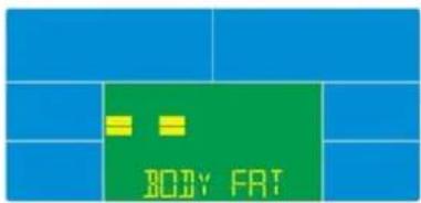
text_image
BODY FAT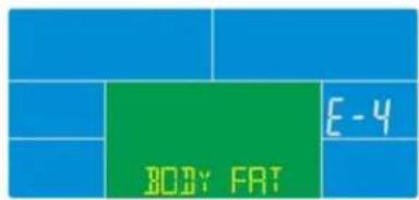
text_image
BODY FAT E-4Messages d'erreur
text_image
iConsole+ iconsole

text_image
iConsole+ iconsole+