PPS11810 - Laboratory power supply VOLTCRAFT - Free user manual and instructions
Find the device manual for free PPS11810 VOLTCRAFT in PDF.
Document temporarily unavailable
The manual is currently being transferred to our new server. It will be accessible again in a few hours. Thank you for your patience.
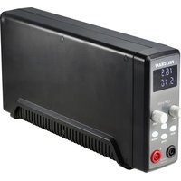
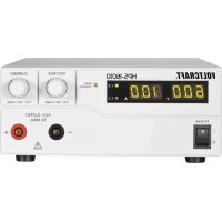
| Product type | Adjustable laboratory power supply |
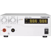
| Brand | Voltcraft |
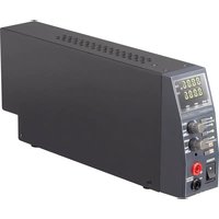
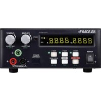
| Model | PPS11810 |
| Input voltage | 100-240 V~, 50/60 Hz |
| Max. input current | 1.2 A (230 V~) / 2.4 A (100 V~) |
| Max. output power | 180 W |
| Output voltage | 1-18 V DC |
| Output current | 0-10 A (front output limited to 5 A) |
| Display accuracy | ±0.2% + 3 digits |
| Overvoltage protection (OVP) | Yes, programmable trigger level |
| Overload protection (OLP) | Yes |
| Overtemperature protection (OTP) | Yes, with temperature-controlled fan |
| Display | 2-line LED (voltage, current) with CV/CC indicators |
| Adjustment | Digital potentiometers (coarse/fine) for voltage and current |
| Operating modes | Normal, Preset (3 memories), Remote Ctrl (external), Set (programming) |
| Remote control | Via external voltage (0-5 V DC) or potentiometer (5 kOhm) and on/off contact |
| PC interface | USB, software included (Windows XP to 8) |
| Software functions | Time programming (20 sequences, up to 999 cycles), data logging |
| Outputs | Front: 4 mm safety sockets (5 A max); Rear: screw terminals (rated current) |
| Protection class | 1 (with earth grounding) |
| Mains fuse | 5 x 20 mm, F6AL250V |
| Cooling | Temperature-controlled fan (0-100%) |
| Operating temperature | 0 to +45 °C |
| Dimensions (W x H x D) | 200 x 90 x 208 mm |
| Weight | 2.4 kg |
Frequently Asked Questions - PPS11810 VOLTCRAFT
User questions about PPS11810 VOLTCRAFT
0 question about this device. Answer the ones you know or ask your own.
Ask a new question about this device
Download the instructions for your Laboratory power supply in PDF format for free! Find your manual PPS11810 - VOLTCRAFT and take your electronic device back in hand. On this page are published all the documents necessary for the use of your device. PPS11810 by VOLTCRAFT.