Carmig - Welding machine GYS - Free user manual and instructions
Find the device manual for free Carmig GYS in PDF.
| Features | Details |
|---|---|
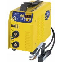
| Device type | MIG/MAG welding machine |
| Power supply | 230 V |
| Welding current | From 30 to 150 A |
| Weight | Approximately 15 kg |
| Dimensions | 400 x 300 x 500 mm |
| Usage | Welding of ferrous and non-ferrous metals, ideal for DIY work and repairs. |
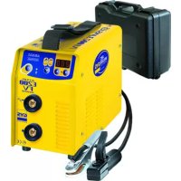
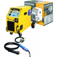
| Included accessories | MIG torch, ground clamp, earth cable, user manual |
| Maintenance | Regularly check connections, clean the torch nozzle, and replace electrode wires if necessary. |
| Safety | Use personal protective equipment (gloves, welding mask), work in a well-ventilated area. |
| Warranty | 2 years |
| General information | Device designed for amateur and professional users, with good value for money. |
Frequently Asked Questions - Carmig GYS
Download the instructions for your Welding machine in PDF format for free! Find your manual Carmig - GYS and take your electronic device back in hand. On this page are published all the documents necessary for the use of your device. Carmig by GYS.
USER MANUAL Carmig GYS
INSTALLATION – FONCTIONNEMENT PRODUIT
ANOMALIES, CAUSES, REMÈDES
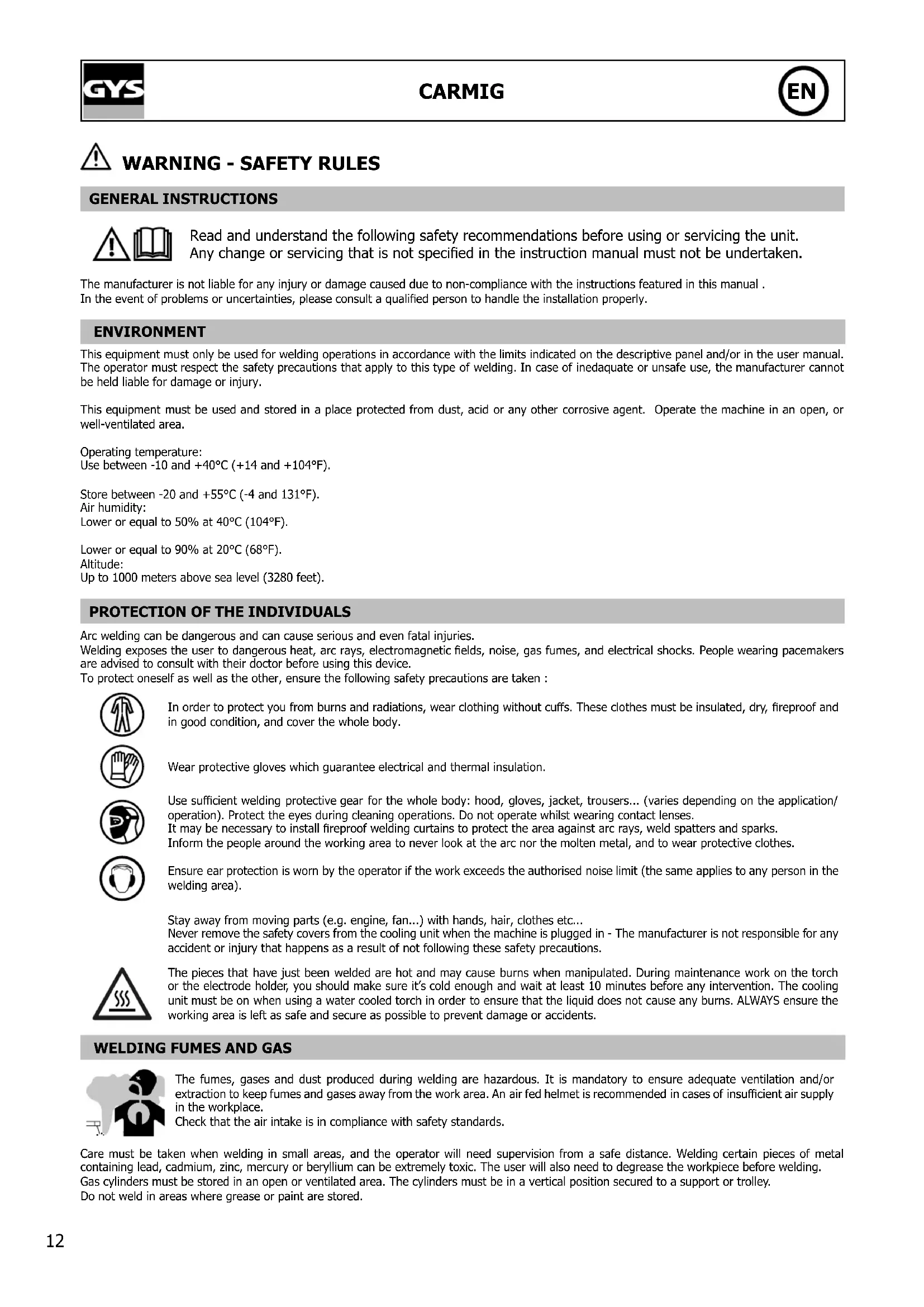
GENERAL INSTRUCTIONS Read and understand the following safety recommendations before using or servicing the unit. Any change or servicing that is not specied in the instruction manual must not be undertaken. The manufacturer is not liable for any injury or damage caused due to non-compliance with the instructions featured in this manual . In the event of problems or uncertainties, please consult a qualied person to handle the installation properly. ENVIRONMENT This equipment must only be used for welding operations in accordance with the limits indicated on the descriptive panel and/or in the user manual. The operator must respect the safety precautions that apply to this type of welding. In case of inedaquate or unsafe use, the manufacturer cannot be held liable for damage or injury. This equipment must be used and stored in a place protected from dust, acid or any other corrosive agent. Operate the machine in an open, or well-ventilated area.Operating temperature:Use between -10 and +40°C (+14 and +104°F).Store between -20 and +55°C (-4 and 131°F).Air humidity:Lower or equal to 50% at 40°C (104°F).Lower or equal to 90% at 20°C (68°F).Altitude:Up to 1000 meters above sea level (3280 feet).
PROTECTION OF THE INDIVIDUALS
Arc welding can be dangerous and can cause serious and even fatal injuries. Welding exposes the user to dangerous heat, arc rays, electromagnetic elds, noise, gas fumes, and electrical shocks. People wearing pacemakers are advised to consult with their doctor before using this device.To protect oneself as well as the other, ensure the following safety precautions are taken : In order to protect you from burns and radiations, wear clothing without cus. These clothes must be insulated, dry, reproof and in good condition, and cover the whole body.Wear protective gloves which guarantee electrical and thermal insulation. Use sucient welding protective gear for the whole body: hood, gloves, jacket, trousers... (varies depending on the application/ operation). Protect the eyes during cleaning operations. Do not operate whilst wearing contact lenses.It may be necessary to install reproof welding curtains to protect the area against arc rays, weld spatters and sparks.Inform the people around the working area to never look at the arc nor the molten metal, and to wear protective clothes. Ensure ear protection is worn by the operator if the work exceeds the authorised noise limit (the same applies to any person in the welding area).Stay away from moving parts (e.g. engine, fan...) with hands, hair, clothes etc... Never remove the safety covers from the cooling unit when the machine is plugged in - The manufacturer is not responsible for any accident or injury that happens as a result of not following these safety precautions. The pieces that have just been welded are hot and may cause burns when manipulated. During maintenance work on the torch or the electrode holder, you should make sure it’s cold enough and wait at least 10 minutes before any intervention. The cooling unit must be on when using a water cooled torch in order to ensure that the liquid does not cause any burns. ALWAYS ensure the working area is left as safe and secure as possible to prevent damage or accidents.
WELDING FUMES AND GAS
The fumes, gases and dust produced during welding are hazardous. It is mandatory to ensure adequate ventilation and/or extraction to keep fumes and gases away from the work area. An air fed helmet is recommended in cases of insucient air supply in the workplace.Check that the air intake is in compliance with safety standards. Care must be taken when welding in small areas, and the operator will need supervision from a safe distance. Welding certain pieces of metal containing lead, cadmium, zinc, mercury or beryllium can be extremely toxic. The user will also need to degrease the workpiece before welding. Gas cylinders must be stored in an open or ventilated area. The cylinders must be in a vertical position secured to a support or trolley. Do not weld in areas where grease or paint are stored.13 CARMIG
Protect the entire welding area. Compressed gas containers and other inammable material must be moved to a minimum safe distance of 11 meters. A re extinguisher must be readily available. Be careful of spatter and sparks, even through cracks. It can be the source of a re or an explosion. Welding of sealed containers or closed pipes should not be undertaken, and if opened, the operator must remove any inammable or explosive materials (oil, petrol, gas...). Grinding operations should not be directed towards the device itself, the power supply or any ammable materials. GAS BOTTLE Gas leaking from the cylinder can lead to suocation if present in high concentrations around the work area. Transport must be done safely: Cylinders closed and product o. Always keep cylinders in an upright position securely chained to a xed support or trolley. Close the bottle after any welding operation. Be wary of temperature changes or exposure to sunlight. Cylinders should be located away from areas where they may be struck or subjected to physical damage. Always keep gas bottles at a safe distance from arc welding or cutting operations, and any source of heat, sparks or ames. Be careful when opening the valve on the gas bottle, it is necessary to remove the tip of the valve and make sure the gas meets your welding requirements. ELECTRIC SAFETY The machine must be connected to an earthed electrical supply. Use the recommended fuse size. An electrical discharge can directly or indirectly cause serious or deadly accidents . Do not touch any live part of the machine (inside or outside) when it is plugged in (Torches, earth cable, cables, electrodes) because they are connected to the welding circuit. Before opening the device, it is imperative to disconnect it from the mains and wait 2 minutes, so that all the capacitors are discharged. Do not touch the torch or electrode holder and earth clamp at the same time. Damaged cables and torches must be changed by a qualied and skilled professional. Make sure that the cable cross section is adequate with the usage (extensions and welding cables). Always wear dry clothes in good condition, in order to be insulated from the electrical circuit. Wear insulating shoes, regardless of the environment in which you work in. EMC CLASSIFICATION These Class A devices are not intended to be used on a residential site where the electric current is supplied by the public network, with a low voltage power supply. There may be potential diculties in ensuring electromagnetic compatibility on these sites, because of the interferences, as well as radio frequencies. This equipment CARMIG complies with IEC 61000-3-12, provided that the power of the short-circuit Ssc is equal to or greater than 1.4 MVA at the interface between the machine and the mains power network. It is the responsibility of the installer or user of the equipment to ensure if necessary by consulting the operator of the mains electricity, that the equipment is only connected to a power supply where the power of short-circuit ssc is equal to or greater than 1.4 MVA. This equipment complies with the IEC 61000-3-11 standard. ELECTROMAGNETIC INTERFERENCES The electric currents owing through a conductor cause electrical and magnetic elds (EMF). The welding current generates an EMF eld around the welding circuit and the welding equipment. The EMF elds may disrupt some medical implants, such as pacemakers. Protection measures should be taken for people wearing medical implants. For example, access restrictions for passers-by or an individual risk evaluation for the welders. All welders should take the following precautions in order to minimise exposure to the electromagnetic elds (EMF) generated by the welding circuit::
- position the welding cables together – if possible, attach them;
- keep your head and torso as far as possible from the welding circuit;
- never enroll the cables around your body;
- never position your body between the welding cables. Hold both welding cables on the same side of your body;
- connect the earth clamp as close as possible to the area being welded;
- do not work too close to, do not lean and do not sit on the welding machine
- do not weld when you’re carrying the welding machine or its wire feeder. People wearing pacemakers are advised to consult their doctor before using this device. Exposure to electromagnetic elds while welding may have other health eects which are not yet known.14 CARMIG
RECOMMANDATIONS TO ASSES THE AREA AND WELDING INSTALLATION Overview The user is responsible for installing and using the arc welding equipment in accordance with the manufacturer’s instructions. If electromagnetic disturbances are detected, it is the responsibility of the user of the arc welding equipment to resolve the situation with the manufacturer’s technical assistance. In some cases, this remedial action may be as simple as earthing the welding circuit. In other cases, it may be necessary to construct an electromagnetic shield around the welding power source and around the entire piece by tting input lters. In all cases, electromagnetic interferences must be reduced until they are no longer bothersome. Welding area assessment Before installing the machine, the user must evaluate the possible electromagnetic problems that may arise in the area where the installation is planned. . In particular, it should consider the following: a) the presence of other power cables (power supply cables, telephone cables, command cable, etc...)above, below and on the sides of the arc welding machine. b) television transmitters and receivers ; c) computers and other hardware; d) critical safety equipment such as industrial machine protections; e) the health and safety of the people in the area such as people with pacemakers or hearing aids; f) calibration and measuring equipment g)The isolation of the equipment from other machinery. The user will have to make sure that the devices and equipments that are in the same room are compatible with each other. This may require extra precautions; h) make sure of the exact hour when the welding and/or other operations will take place. The surface of the area to be considered around the device depends on the the building’s structure and other activities that take place there. The area taken in consideration can be larger than the limits determined by the companies. Welding area assessment Besides the welding area, the assessment of the arc welding systems intallation itself can be used to identify and resolve cases of disturbances. The assessment of emissions must include in situ measurements as specied in Article 10 of CISPR 11. In situ measurements can also be used to conrm the eectiveness of mitigation measures. RECOMMENDATION ON METHODS OF ELECTROMAGNETIC EMISSIONS REDUCTION a. National power grid : The arc welding machine must be connected to the national power grid in accordance with the manufacturer’s recommendation. If interferences occur, it may be necessary to take additional preventive measures such as the ltering of the power suplly network. Consideration should be given to shielding the power supply cable in a metal conduit. It is necessary to ensure the shielding’s electrical continuity along the cable’s entire length. The shielding should be connected to the welding current’s source to ensure good electrical contact between the conduct and the casing of the welding current source.. b. Maintenance of the arc welding equipment : The arc welding machine should be be submitted to a routine maintenance check according to the manufacturer’s recommendations. All accesses, service doors and covers should be closed and properly locked when the arc welding equipment is on.. The arc welding equipment must not be modied in any way, except for the changes and settings outlined in the manufacturer’s instructions. The spark gap of the arc start and arc stabilization devices must be adjusted and maintained according to the manufacturer’s recommendations. c. Welding cables : Cables must be as short as possible, close to each other and close to the ground, if not on the ground. d. Electrical bonding : consideration shoud be given to bonding all metal objects in the surrounding area. However, metal objects connected to the workpiece increase the riskof electric shock if the operator touches both these metal elements and the electrode. It is necessary to insulate the operator from such metal objects. e. Earthing of the welded part : When the part is not earthed - due to electrical safety reasons or because of its size and its location (which is the case with ship hulls or metallic building structures), the earthing of the part can, in some cases but not systematically, reduce emissions It is preferable to avoid the earthing of parts that could increase the risk of injury to the users or damage other electrical equipment. If necessary, it is appropriate that the earthing of the part is done directly, but in some countries that do not allow such a direct connection, it is appropriate that the connection is made with a capacitor selected according to national regulations. f. Protection and plating : The selective protection and plating of other cables and devices in the area can reduce perturbation issues. The protection of the entire welding area can be considered for specic situations. TRANSPORT AND TRANSIT OF THE WELDING MACHINE Do not use the cables or torch to move the machine. The welding equipment must be moved in an upright position. Do not place/carry the unit over people or objects. Never lift the machine while there is a gas cylinder on the support shelf. A clear path is available when moving the item. The removal of the wire reel from the machine is recommended before undertaking any lifting operation. Stray welding currents/voltages may destroy earth conductors, damage electrical equipment or cause components to warm up which may cause a re.
- All welding connections must be rmly secured, check regularly !
- Check that the metal piece xation is strong and without any electrical problems !
- Attach or hang all the electrically conductive elements, such as the trolley and slinging equipment, in order to insulate them
- Do not place any electrical equipment, such as drills or grinders, on top of the welding machine without insulating them !
- Always place welding torches or electrodes holders on an insulated surface when they’re not in use !15 CARMIG
- Ensure the work area has sucient ventillation for welding, and that there is easy access to the control panel.
- The machine must be placed in a sheltered area away from rain or direct sunlight.
- The machine must not be used in an area with conductive metal dusts.
- The machine protection level is IP21, which means : - Protection against acess to dangerous parts from solid bodies of a ≥12.5mm diameter and, - Protection against vertically falling drops.
- The power cables, extensions and welding cables must be fully uncoiled to prevent overheating. The manufacturer does not incur any responsability regarding damages to both objects and persons that result from an incorrect and/or dangerous use of the machine . MAINTENANCE / RECOMMENDATIONS
- Maintenance should only be carried out by a qualied person. Annual maintenance is recommended.
- Ensure the machine is unplugged from the mains, and wait for two minutes before carrying out maintenance work. DANGER High Voltage and Currents inside the machine.
- Remove the casing 2 or 3 times a year to remove any excess dust. Take this opportunity to have the electrical connections checked by a qualied person, with an insulated tool.
- Regularly check the condition of the power supply cable. If the power cable is damaged, it must be replaced by the manufacturer, its after sales service or an equally qualied person.
- Ensure the ventilation holes of the device are not blocked to allow adequate air circulation.
- Do not use this equipment to thaw pipes, to charge batteries, or to start any engine. RISK OF INJURY DUE TO MOVING PARTS! The wire feeders contain moving parts that may catch hand, hair, clothes or tools which can lead to injuries! Take extra care.
- Do not place your hand on mobile/pivoting/wire feeding parts of the machine!
- Make sure that all panels remain closed when in use !
PRESENTATION The CARMIG is a traditional machine for welding semi-automatic MIG/MAG (DC current). This machine can weld all types of wire : Steel, Stainless Steel and Aluminium. ELECTRICITY SUPPLY The welders are tted with a 16 A socket type EN 60309-1 which must be connected to a three-phase 400V (50 - 60 Hz) power supply tted with four wires and one earthed neutral. The absorbed eective current (I1e) is displayed on the machine, for optimal use. Check that the power supply and its protection (fuse and/or circuit breaker) are compatible with the current needed by the machine. In some countries, it may be necessary to change the plug to allow the use at maximum settings. The Carmig has to be plugged on a 400 V (50Hz) power socket WITH earth and protected by a circuit breaker 10A and a dierential 30mA. This device should only be used with a three-phase power supply system with four wires and an earthed neutral one. DEVICE PRESENTATION (FIGURE II, PAGE 2)
2- Power Settings - 1 switches with 7 positions: for ad-
justment of the welding voltage output. The adjustment of the output voltage is proportional to the thickness of the work piece.
3- Control panel and table for SMART feature
4- European standard torch connection.
5- Thermal Protection light: Indicates when a cool-down
period is necessary following intensive use.
9- Gas bottle support (max 1 bottle of 10m3).
10- Fastening chain for bottles. Warning: fasten the
chain securely (see V-1)
14- Torch Cable support16
SEMI-AUTOMATIC WELDING FOR STEEL / STAINLESS STEEL (MAG MODE) These machines can weld Steel and Stainless Steel wires of 0.6/0.8 or 1.0mm (g III - A) The machine is delivered equipped to operate with Ø0.8mm Steel/Stainless steel wire: contact tip, roller throat and sleeve of the torch are suitable for this application. Should you wish to use 0.6mm wire, you will need to change the contact tip. The wire reel is reversible (0.6 / 0.8 mm) and will need to be inserted into the machine so that the gure 0.6 is visible. For welding with Ø 1.0 mm wire, you will need to use a specic roller and contact tip. For welding with Steel or Stainless Steel we recommend to use Argon + CO2 (Ar+CO2). The proportion of CO2 required will vary depending on the use. For specic gas requirements, please contact your gas distributor. The gas ow in steel is between 12 and 18 Litres/minute depending on the environment and experience of the welder. SEMI-AUTOMATIC WELDING FOR ALUMINIUM (MIG MODE) This device can also weld Ø0.8 mm aluminium wire (g III-B) Welding on aluminium needs a specic gas: Argon (Ar). When welding aluminium, the gas ow-rate should be tuned between 15 and 25l/min according to the environment and the welder experience. Here are the dierences between use with steel and use with aluminium : - Rollers: use specic rollers for aluminium welding. - Pressure of motor pressure rolls on the wire: put a minimum of pressure in order not to squash the wire. - Use the capillary tube (designed to guide the wire between the drive rolls and the euro connector) only when welding in MIG/MAG. - Torch: use a special aluminium torch which is equipped with a Teon (not included) sheathing in order to reduce fric- tion. DO NOT cut the sheathing close to the joint! The sheathing is needed to guide the wire from the rolls. - Contact tube: use a Ø0.8 mm special aluminium contact tube (ref.: 041509 – not included). PROCESS OF REELS AND TORCHES ASSEMBLY (FIGURE V, PAGE 3)
- Remove the Nozzle from the torch by turning clockwise and then remove the contact tip, leaving the support and the spring on the torch. This product takes Ø 200/300 mm wire reel (compatible coil with plastic carcass and ecological wire carcass) Open the door of the machine.
- Place the reel on the driving pin (3) of the reel support. To install a 200mm wire reel, t an adaptor on the support (ref. 042889). - Adjust the reel brake (4) to avoid the reel inertia tangling the wire when welding stops. Do not overtighten! Tighten the xing screw (2).
- The electrical rollers (7) are double groove rollers (Ø 0,8/ Ø 1 or Ø 1/ Ø 1,2). The indication on the visible side of the roller is the diameter in use. For a Ø1 mm wire, use the Ø1 groove.
- For the rst use : - Release the xing screw which guides the wire - Fit the rollers, then tighten the screw retainer (8). - Put the wire guide in place (6) as close as possible to the roller without contact, then tighten the xing screw.
- To set the adjusting knob of the drive rollers (5), proceed as follows: Loosen the knob fully, start the motor by pres- sing the torch trigger, tighten the adjustment knob whilst pressing the trigger. Bend the wire where it comes out of the nozzle. Put a nger on the bended wire to avoid any movement. The setting is correct when the guide roller slides over the wire even when it is blocked at the end of the torch.
- Adjustment of the tension on the wire (5): on the scale 3-4 for steel and 2-3 for aluminium. GAS COUPLING Connect a pressure regulator to the gas bottle. Connect the welding machine using the pipes, and place the two clamps to avoid leakages. Set the gas ow by adjusting the dial located on the pressure regulator. NB : to help facilitate the adjustment of the gas ow, operate the drive rollers by pressing the trigger of the torch (ensure that the drive roller is completely loose so the wire is not fed through).17 CARMIG
The CARMIG machines can accommodate reels of 200 or 300 mm diameter. Below are the dierent combinations possible: Reel type Torch Gaz Steel Ø 300 Steel torch included Argon + CO2 or Pure CO2 Ø 200 INOX Ø 200 CuSi3 Ø 200 Pure argon CuAl8 Ø 200 Alu AlMg5* Ø 300 Alu torch not included Ø 200
2- Wire speed regulator.
3- « SMART » settings table MIG/MAG.
4- Thermal Protection light.
CARMIG feature allows you to adjust the voltage and the wire speed. Use the SMART table to nd the correct settings based on the type of wire, and the thickness of the metal work piece. Then based on the recommendation indicated, simply select:
- The voltage (rotating witch with 7 positions)
- Wire speed - adjust the regulator (2) to the colour zone indicated. Examples: To weld 0.8 mm thick steel, using 0.8 mm diameter steel wire:
- Move the rotating switch (1) to the position 1.
- Move the regulator (2) to the zone of lightest blue colour and adjust “by sound” if required.
ADVICE AND THERMAL PROTECTION
- Respect the normal rules of welding
- Leave the machine plugged in after welding to allow it to cool
- Thermal Protection : The LED will illuminate. Cooling will take between 10 and 15 minutes depending on the ambient temperature. MAINTENANCE
- Maintenance should only be carried out by a qualied person.
- Switch the machine o, ensure it is unplugged, and that the ventilator inside has stopped before carrying out mainte- nance work. (DANGER High Voltage and Currents).
- GYS France recommends removing the steel cover 2 or 3 times a year to remove any excess dust. Take this opportunity to have the electrical connections checked by a qualied person with an insulated tool.
- Regularly check the condition of the power supply cord. If damaged, it will need to be replaced by the manufacturer, its’ after sales service or a qualied person.
- Ensure the ventilation holes of the device are not blocked to allow adequate air circulation. OUR ADVICE
- Ensure the ventilation holes of the device are not blocked to allow adequate air circulation.
- Change the contact tip and the nozzle of the torch on a regular basis.
- Ensure the torch and sheath are free from aluminium and steel dust.
- Avoid MIG/MAG welding in draftee areas.18 CARMIG
The welding wire speed is not constant. Cracklings blocking up the ope- ning. Clean out the contact batch or change it and replace the anti-adherence product. The wire skids in the rollers. - Control the roller pressure or replace it. - Wire diameter non-consistent with roller - Covering wire guide in the torch not consistent with wire. The unwinding motor doesn’t operate. Reel or roller brake too tight. Release the brake and rollers. Electrical supply problem. Check that the running button is on the position on. Bad wire unwinding. Covering wire guide dirty or damaged. Clean or replace Reel brake too tight Release the brake No welding current Bad connection to the mains supply. Check the branch connection and ensure it is fed by 3 phases. Bad earth connection. Control the earth cable (connection and clamp condition). Power contactor inoperative. Control the torch trigger. The WIRE rubs down after the rollers. Covering WIRE guide crushed. Check the covering and torch body. Locking of the wire in the torch Clean or replace. No capillary tube. Check the presence of capillary tube. Wire speed too fast Reduce the wire speed The welding cord is porous. The gas ow is not sucient. Adjusting range 15 to 20 L / min. Clean the working metal. Gas bottle empty. Replace it. Gas quality non-satisfying. Replace it. Air ow or wind inuence. Avert air blast, protect welding area. Gas nozzle too full. Clean or replace the gas nozzle. Bad wire quality. Use adapted WIRE for MIG-MAG welding. Surface to weld in bad condition. (rust, etc…) Clean the working parts before welding. Very signicant ashing parti- cules. Arc voltage too low or too high. See welding settings. Bad earth connection. Check and place the earth cable to have a better connec- tion. Protecting gas insucient. Adjust the gas ow. No gas at the torch output. Bad gas connection. See if the gas coupling beside the engine is well connec- ted. WARRANTY The warranty covers faulty workmanship for 2 years from the date of purchase (parts and labour). The warranty does not cover:
- Damages due to misuse (power supply error, dropping of equipment, disassembling).
- Environment related failures (pollution, rust, dust). In case of failure, return the unit to your distributor together with: - The proof of purchase (receipt etc ...) - A description of the fault reported19 CARMIG
WAARSCHUWING - VEILIGHEIDSINSTRUCTIES
) / Rate current output (I
) / Conventional voltage output (U