— Motorcycle — Mode d'emploi PDF")
RR 4T 400 (2008) - Motorcycle Beta - Free user manual and instructions
Find the device manual for free RR 4T 400 (2008) Beta in PDF.

| Technical Specifications | Single-cylinder 4-stroke engine, 398 cc, liquid-cooled |
|---|---|
| Power | Approximately 40 hp at 8,000 rpm |
| Transmission | 6-speed gearbox |
| Front Suspension | 48 mm inverted fork, 300 mm travel |
| Rear Suspension | Adjustable shock absorber, 300 mm travel |
| Front Brakes | 260 mm disc, 2-piston caliper |
| Rear Brakes | 240 mm disc, 1-piston caliper |
| Weight | Approximately 120 kg dry weight |
| Fuel Tank Capacity | 9.5 liters |
| Recommended Use | Enduro, off-road touring |
| Maintenance | Oil change every 1,500 km, regular brake and tire checks |
| Safety | Helmet and protective gear recommended |
| General Information | 2008 model, designed for experienced riders |
Frequently Asked Questions - RR 4T 400 (2008) Beta
User questions about RR 4T 400 (2008) Beta
0 question about this device. Answer the ones you know or ask your own.
Ask a new question about this device
Download the instructions for your Motorcycle in PDF format for free! Find your manual RR 4T 400 (2008) - Beta and take your electronic device back in hand. On this page are published all the documents necessary for the use of your device. RR 4T 400 (2008) by Beta.
USER MANUAL RR 4T 400 (2008) Beta
Pirelli MT 21 Rallycross Tube Type
cerchio anteriore 21x1,6
cerchio posteriori 18x2,15
DIMENSIONI RUOTE (MOTARD) Trasm. secondaria 15/43
copertura anteriore 120/70-17 58W o 58H
copertura posteriori 150/60-17 66W o 66H
cerchio anteriore 17x3,5
Thanks for you preference, and have a good time! This handbook contains the information you need to properly operate and maintain your motorcycle.
The data and specifications provided in this manual does not constitute an engagement on the part of BETAMOTOR S.p.A. BETAMOTOR reserves the right to make any changes and improvements to its models at any moment and without notice.
IMPORTANT
We recommend you to check all the tightenings after the first one or two hours' ride over rough ground. Special attention should be paid to the following parts:
- rear sprocket
- ensure that the footrests are properly fixed
front/rear brake levers/calipers/discs - check that the plastics are properly fastened
- engine bolts
- shock absorber bolts/swingarm
- wheel hubs/spokes
rear frame - pipe connections
- tensioning the chain
IMPORTANT
For any servicing requirements, please get in contact with Betamotor's authorized service network.
Operating instructions 81
Ecologic guide 81
Riding safety 82
CHAPTER 1 GENERAL INFORMATION 83
Vehicle identification data 84
Delivery 84
Load 85
Tyres. 85
Steering lock 86
Familiarizing with your vehicle 87
Controls 88
94
Wiring diagrams 98
Electrical devices 100
Euro 3 devices 101
Checks to be performed before each ride 104
Recommended lubricants 105
Running-in 105
Starting the engine 106
Choke and ldling settin 107
Refuelling. 108
CHAPTER 3 CHECKS AND MAINTENANCE 109
Motor oil level check 110
Motor oil and oil filter substitution 111
Check the level of the front and rear brake fluid and bleeding 114
Check the front and rear brake pads 116
Check the oil level in the hydraulic clutch and bleeding 117
Fork oil 118
Air filter 119
Spark plug 120
Carburetor 121
Coolant 124
Removing the plastics 125
Drive chain maintenance and wear 129
Suspensions: telescopic fork and shock absorber 130
Charging the battery 132
Cleaning and checking the vehicle 133
Scheduled maintenance 134
Prolonged inactivity 135
CHAPTER 4 ADJUSTMENTS. 137
Brake adjustment: front lever and brake pedal 138
Adjusting the home position of the clutch lever 139
Adjusting the handlebars 139
Adjusting the throttle control cable 140
Checking and adjusting the steering play 140
Tensioning the chain 141
Adjusting the headlight 142
CHAPTER 5 REPLACEMENTS 143
Replacing the brake pads: front and rear 144
Replacing the headlight bulbs 146
Replacing the rear light bulb. 146
Replacing the exhaust-pipe 147
CHAPTER 6 TROUBLESHOOTING 149
INDEX 151
OPERATING INSTRUCTIONS
- The vehicle must be accompanied by: number-plate, registration document, tax disc and insurance.
- Do not carry animals, pets or loose objects that can stick out from the vehicle.
- Riding without a crash helmet is forbidden.
Always ride with the low beam on. - Any modifications of the engine or other parts resulting in a power and/or speed increase are punishable by severe sanctions including the confiscation of the vehicle.
- To protect your safety and that of others, always drive carefully and with your helmet on.
WARNING
Any modifications and tampering with the vehicle during the warranty period exempt the manufacturer from all responsibility and invalidate warranty.
ECOLOGIC GUIDE
- Every vehicle powered by an internal combustion engine produces an amount of noise (noise pollution) and gases (air pollution) which varies with the riding style.
- The abatement of noise and air pollution levels is the duty of everybody. Avoid full throttle starts, sudden acceleration and abrupt braking. This will reduce noise emission as well as the wear and tear of the tyres and mechanical parts, and will also allow a considerable reduction in fuel consumption.
RIDING SAFETY
- Observe the Highway Code.
- Always put on and fasten a homologated helmet.
- Always ride with the low beam on.
Always keep the crash helmet visor clean. - Avoid wearing garments with hanging ends.
- Do not keep sharp or brittle objects in your pockets while riding.
- Properly adjust the rearview mirrors.
- Always ride in a seated position, with both hands on the handlebars and both feet on the footrests.
- Always pay attention and do not allow anything to distract you while riding.
- Do not eat, drink, smoke, use a mobile phone, etc. while riding.
- Do not wear headphones to listen to music while riding.
- Never ride abreast with other vehicles.
- Do not tow and avoid being towed by other vehicles.
- Always keep a safe distance from other vehicles.
- Do not sit on the vehicle when it is on its stand.
- Do not start off while the vehicle is on its stand.
- Do not pull out the stand when the vehicle is facing downhill.
- Avoid swaying and wheelies as they are extremely dangerous for your own and other people's safety as well as for your vehicle.
- Always apply both brakes on dry roads with no gravel and sand. Using one brake may be dangerous and cause uncontrolled skidding.
- To reduce the braking distance, always apply both brakes.
- On wet roads and in off-road riding, drive with care and at moderate speed. Take special care in applying the brakes.
- Do not start the engine in closed places.
CONTENTS
CHAPTER 1 GENERAL INFORMATION
Vehicle identification data
Delivery
Load
Tyres
Steering lock
Familiarizing with your vehicle
Controls
Specifications
Wiring diagram
Electrical devices
1
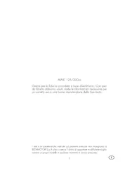
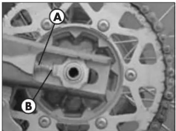
VEHICLE IDENTIFICATION DATA
FRAME IDENTIFICATION
Frame identification data A are stamped on the right side of the steering head tube.
GENERAL INFORMATION
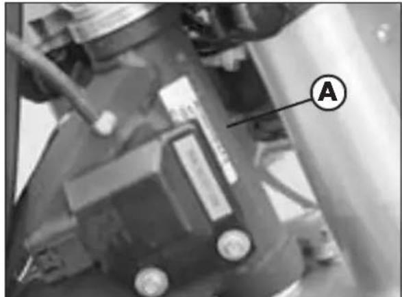
ENGINE IDENTIFICATION
Engine identification data B are stamped in the area shown in the figure.
WARNING:
Tampering with the identification numbers is severely punished by law.
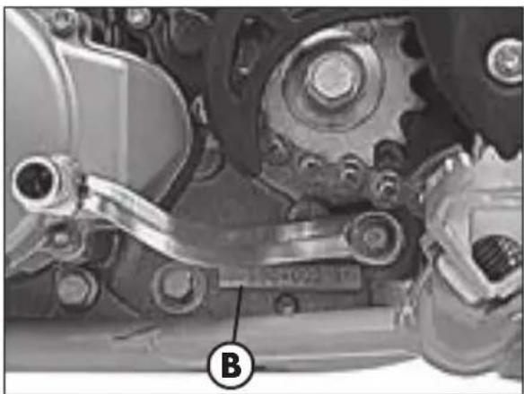
DELIVERY
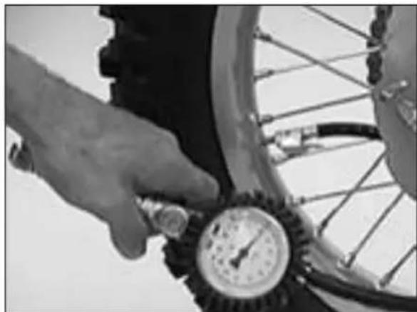
The vehicle is supplied ready for use. However, it is advisable to conduct a few simple checks before riding:
-Check the tyre pressures.
-Check the oil level in the engine.
The following items are supplied as standard: operation and maintenance manual, tool kit (see photo).
LOAD
- To avoid to let the vehicle be unstable, do not carry bulky or heavy objects.
- Do not carry objects that stick from the vehicle or cover the lighting and signalling devices.
TYRES
- Only fit tyres approved by BETAMOTOR. Unsuitable tyres can adversely affect the road holding of the vehicle.
To protect your safety, immediately replace any damaged tyres. - Slick tyres adversely affect the road holding of the vehicle, especially on wet roads and in off-road riding.
Insufficient pressure results in abnormal wear and overheating of the tyres.
The front and rear tyres must have the same tread design.

TYRES PRESSION ENDURORR 400 - 450 - 525
| TYRE | front | rear |
| Offroad | 1,0 bar | 1,0 bar |
| Road | 1,5 bar | 1,8 bar |
| Size | 90/90-21" | 140/80-18" |


Note
The type, condition and pressure of the tyres affect the road holding of the vehicle. For this reason it is essential to check them before each journey.
The size of the tyres is shown in the technical specifications and in the vehicle handbook.
- Check the condition of the tyres before each journey. Inspect the tyres for cuts and for nails or other pointed objects sticking out of them. Regarding the minimum allowable thickness of the tread, observe the regulations in force in your country. We recommend replacing the tyres at the latest when the tread is 2mm thick.
- Check the inflating pressure on a regular basis while the tyres are cold. Proper pressure ensures optimum riding comfort and prolongs the life of the tyres.

STEERING LOCK
The vehicle is supplied with one key and a spare to be used for the steering lock.
WARNING:
Do not keep the spare keys in the vehicle. Keep the keys in a safe and easy-to-reach place. The code number stamped on the keys should be copied on this manual (or elsewhere) so it can be used to ask for duplicates should both keys be lost.
To engage the steering lock, fully turn the handlebars to the right, insert the key, press and turn it fully anticlockwise and then release it.
FAMILIARIZING WITH THE VEHICLE
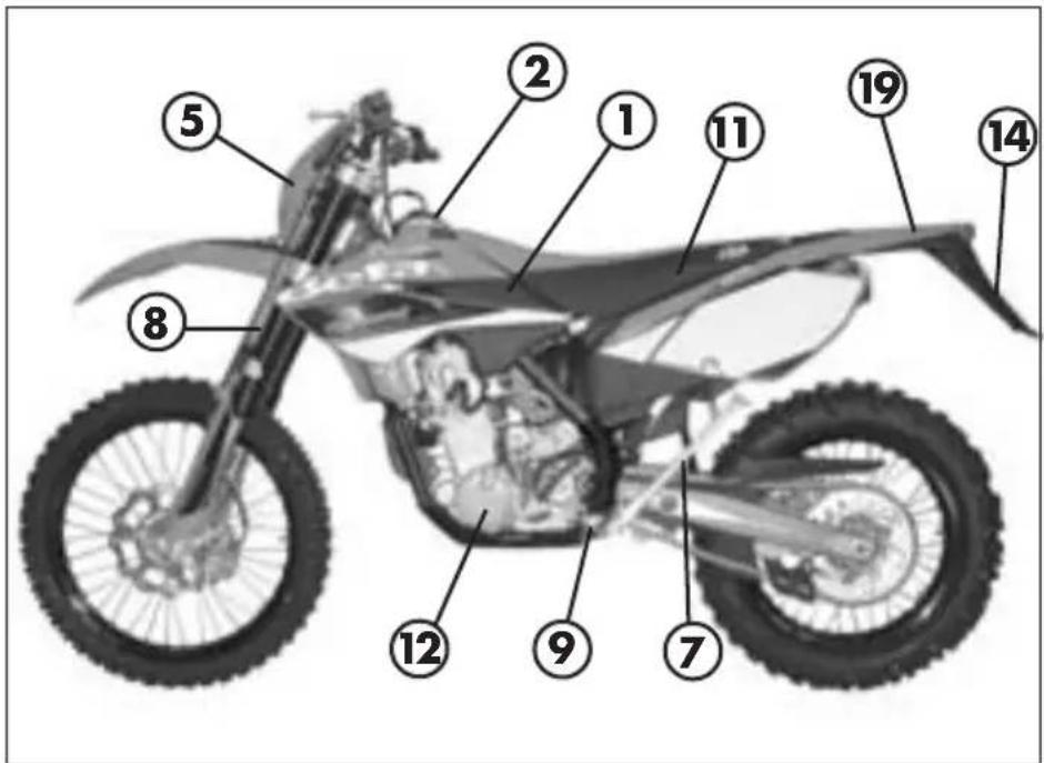
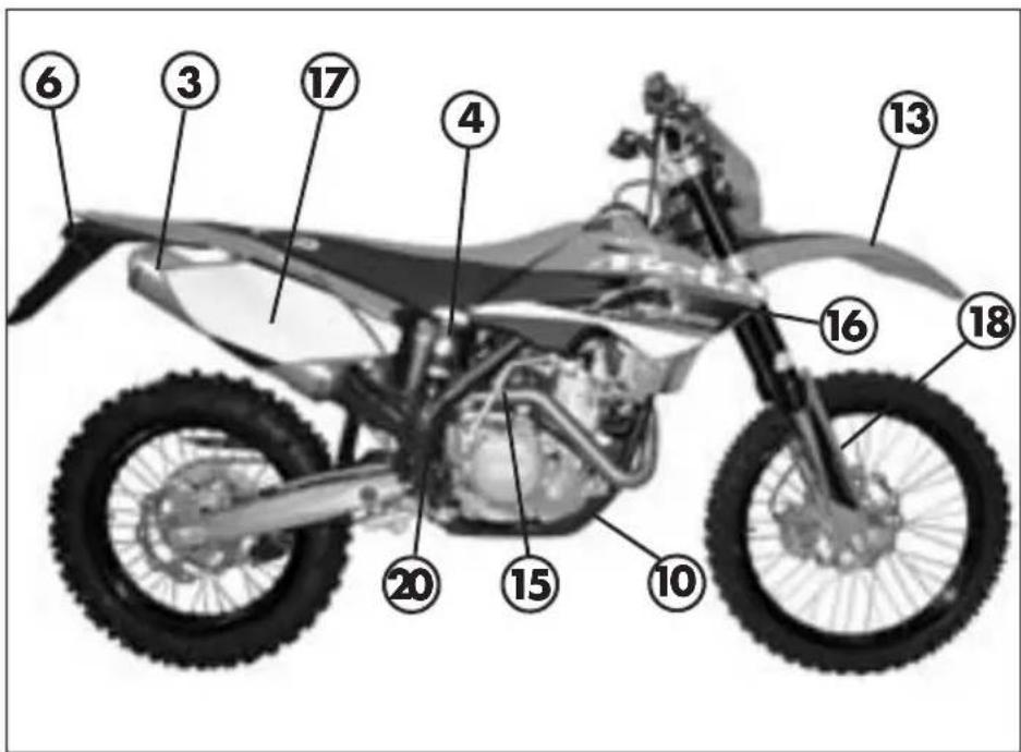
Main parts:
1 - Fuel tank
2 - Tank cap
3 - Silencer
4 - Rear shock absorber
5-Headlight
6 - Rear light
7 - Side stand
8-Fork
9 - Rider's footrests
10 - Lower bumper
(Bumper kit)
11 - Saddle
12 - Engine
13 - Front mudguard
14 - Number-plate holder
15 - Kick-start
16 - Front side panel
17 - Rear side panel
18 - Fork covers
19 - Rear mudguard
20 - Lateral bumper (Bumper kit)
1
CONTROLS
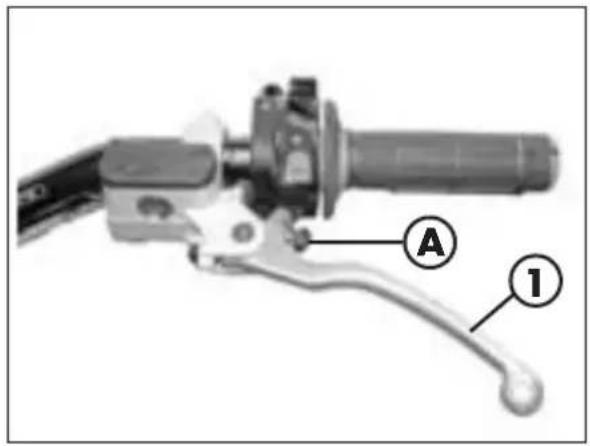
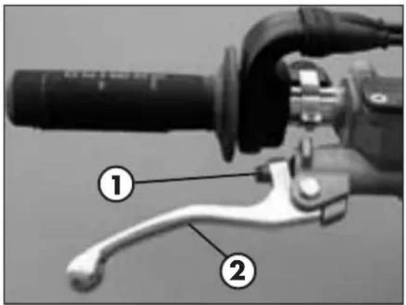
CLUTCH LEVER
Clutch lever 1 is fitted to the left-hand side of the handlebars. Screw A can be used to alter the home position of the lever (see Adjustments).
GENERAL INFORMATION
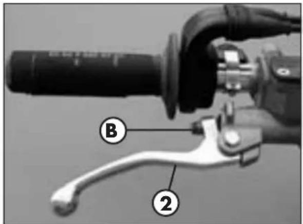
FRONT BRAKE LEVER
Front brake lever 2 is fitted to the right-hand side of the handlebars. Screw B can be used to adjust the home position of the lever (see Adjustments).
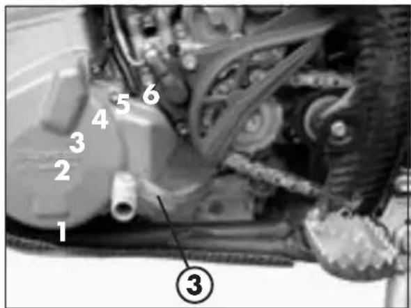
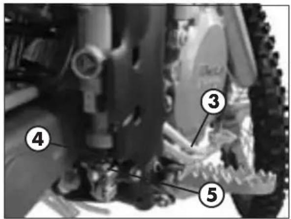
GEARCHANGE LEVER
Gearchange lever 3 is fitted to the left side of the engine. The positions corresponding to the different gears are shown in the figure. The neutral position is between the 1^st and 2^nd gears.
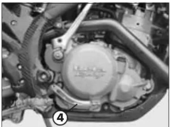
BRAKE PEDAL
Brake pedal 4 is located in front of the right-hand footrest. The position of the pedal can be adjusted to suit the requirements of the driver (see Adjustments).
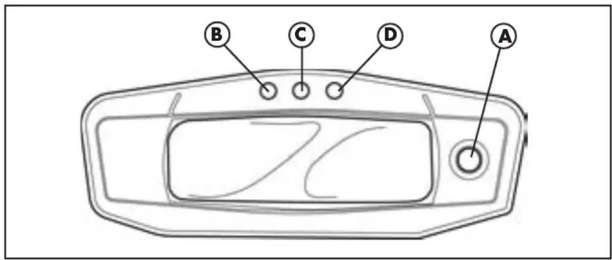
DIGITAL RPM INDICATOR
SCROLL PUSHBUTTON
The instrument panel has a pushbutton A which changes and sets the main functions.
WARNING LIGHTS
The instrument panel has three warning lights. Warning light B, GREEN, indicates turn indicators have been activated.
Warning light C, BLUE, indicates when the high-beam light is ON.
Warning light D, YELLOW, indicates the reserve (not activated)
Important:
When cleaning operation using a high-pressure water jet cleaner, avoid aiming the jet to the digital instrument panel.
CHECK
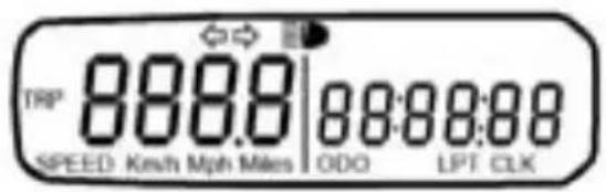
1 screen

2^a screen
3^ screen

4^a screen

Every time the battery is connected, the instrument panel checks all the functions. Once the CHECK phase is complete (around 2 seconds), the last preset operation is displayed.
Every time the vehicle is turned off, the instrument panel stops showing the current information.
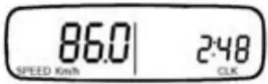
If the SCROLL pushbutton is pushed repeatedly, the functions are displayed in sequenced screens in the following order:
1stscreen
- SPEED rpm indicator
- Odometer ODO
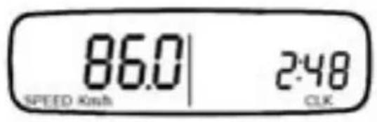
2nd screen
SPEED rpm indicator
- Clock CLK
3rd screen
- SPEED rpm indicator
- Trip odometer TRIP
4th screen
- SPEED rpm indicator
- STP chronometer
1stscreen
- SPEED rpm indicator
- Odometer ODO ...and so on.
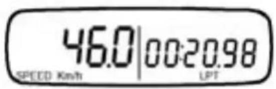
SPEED RPM INDICATOR FUNCTIONS
It indicates the vehicle speed in km/h or mph.
Maximum value: 199 km or mph
CONVERSION PROCEDURE Km/h - Mph and wheel selection
In order to convert km/h to mph, proceed as follows:
- Set the instrument panel on the 1st screen, turn off the vehicle and press the SCROLL pushbutton.
- Start the vehicle keeping the SCROLL pushbutton pushed until the symbol "Km/h" is displayed.
- "Km/h" and "Mph Miles" will be displayed alternately. Press the SCROLL key when the intended unit of measurement is displayed.
- After the conversion, and for a short period of time, the two wheel circumferences available will be shown. Confirm the value to be saved by pressing the SCROLL key at the moment it is shown on the display.
ODOMETER ODO FUNCTIONS
The ODO function saves the kilometres travelled by the vehicle, even with the instrument panel is OFF.
Saving interval: every 2 km
Maximum indication: 99999 km


CLOCK CLK FUNCTIONS
It indicates hours and minutes from 0:00 to 23:59 :59
In order to set the clock, it is necessary to select the screen 2 and hold down the SCROLL pushbutton for approximately three seconds. After this time has elapsed, the desired hour can be selected by pressing the SCROLL key.
When the pushbutton is released after three seconds, the instrument panel will automatically shift to the minutes. Select the minutes by pressing repeatedly the SCROLL pushbutton.
TRIP ODOMETER TRIP FUNCTION
It indicates the distance travelled from the last resetting.
Maximum indication: 999.9km
This parameter can be reset on screen 3 by pushing and holding down the SCROLL key for approximately 3 seconds.
Remark:
The information from this function is lost when the battery is disconnected or tension drops below 6V.
STP CHRONOMETER FUNCTION
It indicates a range from 0 to 99:59.99 (Minutes:Seconds.Hundredths of a second) This counter is controlled by pressing (once the function is displayed) the SCROLL key for approximately 0.5 second.
1stPush: function activation
2nd Push: counters are stopped
3rd Push: STP reset
4th Push: function activation
5th Push: counters are stopped
and so on ....
Remark:
The information from this function is lost when the battery is disconnected or tension drops below 6V.
STARTER BUTTON
Starte button 1 is located on the right-hand side of the handlebars and operate the electri engine starter. Push the button until the engine sterts.
Do not press the button 1 while the engine is running.
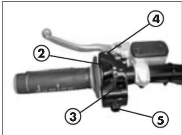
LH SWITCH
Dip switch 2 has three positions:
A' = lights off
B = low beam on
C = high beam on
Button 3 operates the horn.
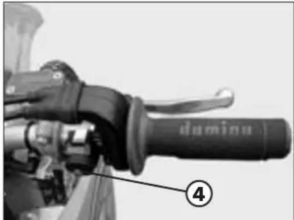
Switch 4 is used to stop the engine. Press the button until the engine stops.
INDICATOR SWITCH
Shifting lever 5 left or right activates the left or right indicators (if installed). When released, the lever returns to the central position. Press it to turn the indicators off.
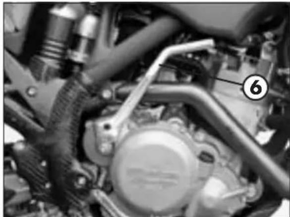
KICKSTART
Kickstart 6 is fitted to the right-hand side of the engine.
The upper part of the kickstart can be oriented.
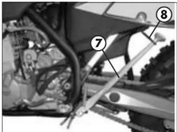
SIDE STAND
Press down side stand 7 with the foot and lean the vehicle against it.
Ensure that the ground is solid and the vehicle stands steadily.
If the vehicle is used off-road, the closed stand can be further fastened by means of rubber band 8.
SPECIFICATIONS
Dry weight - RR 400 - 450 115 kg (front 53 Kg; rear 62 Kg)
Dry weight - RR 525 115,5 kg (front 53,5 Kg; rear 62 Kg)
DIMENSIONS - RR 400 - 450 - 525
maximum length 2270 mm
maximum width 813 mm
overall height 1255 mm
wheelbase 1500 mm
saddle height 940 mm
ground clearance. 320 mm
footrest height 405 mm
FRAME............molybdenum steel with double cradle split above exhaust port
TYRES
pressure bar (off-road) front 1,0 / rear 1,0
pressione bar (road) front 1,5 / rear 1,8
WHEEL DIMENSION (ENDURO) secondary clutch gear 15/45
front cover 90/90-21 54R o 54M
rear cover... 140/80-18 70R o 70M or 130/90-18 70R only
Pirelli MT 21 Rallycross Tube Type
front rim 21x1,6
rear rim 18x2,15
WHEEL DIMENSION (MOTARD) secondary clutch gear 15/43
front cover 120/70-17 58W o 58H
rear cover. 150/60-17 66W o 66H
front rim 17x3,5
rear rim 17x4,25
N.B: Potential tyre change from ENDURO to MOTARD also implies replacing the 15/45 secondary clutch gear with a 15/43 secondary clutch gear (motard Kit option).
CAPACITIES
fuel tank 8 liter
fuel type . . . . . . . . . . . . . . . . . . . . . . . . . . . . . . . . . . . . . . . . . . . . . . . . . . . . . . . . . . . . . . . . . . . . . . . . . . . . . . . . . . . . . . . . . . . . . . . . . . petrol unleaded, with a minimum octane number of 95 (R.O.N.)
including reserve 1 liter
coolant circuit 1,3 liter
motor oil type . synthetic oil (MOTOREX COBRA 15W40)
FRONT SUSPENSION
"Marzocchi" hydraulic upside-down fork (Ø45 mm shafts)
Oil content in the gearshift fork stem:
right 610 cc
left 610 cc
Oil type EB-H16 SAE 7,5
Oil level 90 ±2 mm
Trail 108,5 mm
front wheel travel 290 mm
fork angle 26,5°
REAR SUSPENSION
Single shock absorber with compound lever
shock absorber travel 105 mm
rear wheel travel 300 mm
FRONT BRAKE
255 ~mm floating disc and dual-piston floating caliper
REAR BRAKE
240 mm disc and single-piston floating caliper
ENGINE
Type Single cylinder, 4-stroke, liquid-cooled with countershaft and electric starting
Bore x stroke RR 400 89 x 64 mm
Bore x stroke RR 450 89 x 72 mm
Bore x stroke RR 525 95 x 72 mm
Displacement (cm^3) RR 400 398 cm
Displacement (cm^3) RR 450 448 cm
Displacement (cm^3) RR 525 510 cm
Compression ratio RR 400 - RR 450 - RR 525 11:1
Carburetor see table
| RR 400 | RR 450 | RR 525 | |
| Type Keihin FCR-MX 39 Keihin FCR-MX 39 Keihin FCR-MX 39 | |||
| Carburator-setting number 3900A 3900A 3900B | |||
| Main jet 178 178 178 | |||
| Jet needle OBDVR OBDVR OBDVT | |||
| Idling jet 42 42 42 | |||
| Main air jet 200 200 200 | |||
| Idling air jet | 100 100 | 100 | |
| Needle position | 3. rd from top | 3. rd from top | 3. rd from top |
| Starting jet | 85 | 85 85 | |
| Mixture control screw open 1,25 | 1,25 1,25 | ||
| Slide | 15 15 | 15 | |
| Performance restrictor | slide stop | slide stop | slide stop |
| Stop pump membrane | 858/2,15 mm | 858/2,15 mm | 858/2,15 mm |
| Hot start device | - | - | - |
Lubrication 2 oil pumps
Fuel system . carburettor
Cooling system . forced liquid circulation by pump
Spark plug .NGK DCPR 8 E
Clutch wet, multidisc
Transmission 6-speed with front claw clutch
| RR 400 RR 450 | RR 525 | ||
| Gear ratio 1st gear 14:34 14: | 34 | 14:34 | |
| Gear ratio 2st gear 17:31 17: | 31 | 17:31 | |
| Gear ratio 3st gear 19:28 19: | 28 | 19:28 | |
| Gear ratio 4st gear 22:26 22: | 26 | 22:26 | |
| Gear ratio 5st gear 24:23 24: | 23 | 24:23 | |
| Gear ratio 6st gear 26:21 26: | 21 | 26:21 | |
Valve gear 4 valves
Primary drive. 33/76
Final drive. chain
Chain 135 ZRDK/007
Pinion 215
Rear sprocket 245
Play of valves . intake 0,12 mm
exhaust 0,12 mm
Ignition. DC-CDI without trembler,
with digital variable spark advance, Kokusan-type
Starting electric starter and kickstart
1
WIRING DIAGRAM
GENERAL INFORMATION
WIRING DIAGRAM
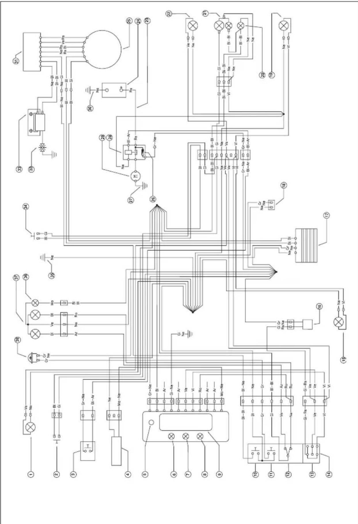
1) RIGHT-HAND FRONT TURN INDICATOR (12V-10W BULB)
2) FRONT BRAKE LIGHT BUTTON
3) START BUTTON
4) WHEEL REVOLUTION SENSOR
5) SCROLL BUTTON
6) TELL TALE LAMP (NO CONNECT)
7) HEADLIGHT TELL TALE LAMP
8) TRAFFICATOR LIGHTS TELL TALE LAMP
9) DISPLAY
10) ENGINE STOP BUTTON
11) HORN BUTTON
12) HEADLIGHT SELECTOR
13) TURN SIGNAL LAMPS SWITCH
14] L.H. SWITCH
15) LH FRONT TURN SIGNAL (BULB 12V-10W)
16) UNIT TURN SIGNAL LAMPS
17) REGULATOR 12V
18) ELECTRIC FAN KIT (option)
19) LEFT-HAND REAR TURN INDICATOR (12V-10W BULB)
20) NUMBER-PLATE LIGHT (1 2V-5W BULB)
21) REAR LIGHT (12V-5/21W BULB)
22) RIGHT-HAND REAR TURN INDICATOR (12V-10W BULB)
23] BATTERY POSITIVE TERMINAL
24) BATTERY 12V-5Ah
25) GENERATOR
261 10A FUSE
271 EARTH BRAID
28) STARTER RELAY
29) STARTER MOTOR
30) BATTERY NEGATIVE TERMINAL
31) ELECTRONIC CONTROL UNIT
32) SPARK.PLUG
33) AT COIL
34) REAR BRAKE LIGHT BUTTON
35) FRAME EARTH
36) PARKING LIGHT BULB, 12V-3W
37) HEADLIGHT WITH 12V-25/25W
38] 12V HORN
Key to colours
Bi = White
Ve = Green
Ma= Brown
Vi = Purple
Bl = Blue
Ne = Black
Gi = Yellow
Rs = Red
Ar = Orange
Az = Sky-blue
R0 = Pink
Gr = Grey
1
ELECTRICAL DEVICES
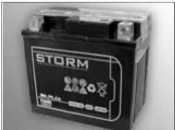
BATTERY
Battery 1 is located under the saddle and requires no maintenance.
It is not necessary to check the level of the electrolyte or top up with water.
Keep the battery terminals clean and, if necessary, protect them with a small quantity of acid-free grease.
Removing the battery
Remove the saddle and disconnect the battery. Be sure to disconnect the negative terminal first and then the positive terminal.
Release rubber band 2.
Remove the battery.
When fitting the battery, insert it with the terminals at the front (see figure). Lastly connect the negative terminal to the battery.
WARNING
To avoid damaging rubber band 2, take care not to pass it over the edge of the battery.
WARNING
Extreme caution should be exercised if the electrolyte (sulphuric acid) should spill out of the battery. The electrolyte can cause severe burns. In case of contact with the skin, rinse generously with water.
Should the electrolyte come into contact with the eyes, rinse with water for at least 15 minutes and immediately seek medical assistance.
Although the battery is sealed, there is a possibility that explosive gases might leak out.
Keep sparks and open flames away from the battery.
Keep exhausted batteries out of the reach of children and dispose of them as prescribed by law.
Do not remove the protections.
When installing the battery, take care to observe the polarity of the connections.
INACTIVITY
If the vehicle is left unused for a long period, remove the battery and charge it with a suitable charger every 15 days. Keep the battery in a dry place at a temperature of 5 - 35^ and out of the reach of children.
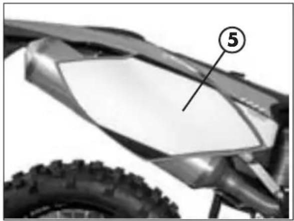
FUSE
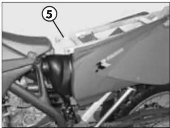
Fuse 3 is located in starting relay 4 underneath right-hand side panel 5. To gain access to the fuse, remove the saddle and lift tilting support 6, where the battery is contained.
The fuse protects the following devices:
- electric starter
- horn
indicators - instrument panel
The starting relay also contains spare fuse 7 (10 amperes).
Always replace a blown fuse with another of the same type.
If the new fuse should also burn out when fitted, immediately contact a specialized BETAMOTOR workshop.
The fuse has a capacity of 10 amperes.
WARNING
Do not on any account fit a larger capacity fuse or attempt to fix a broken fuse.
Unskilled operations could cause a breakdown of the entire electrical system.
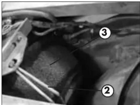
DEVICES FOR E3 VERSION
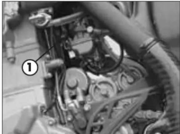
The latest models are E3 type-approved and they differ from prior approvals in that three devices have been introduced:
AIS valve
It is called AIS 1 and it is an air intake system which allows to complete the combustion of some unburned fuels remaining from the thermodynamic cycle.
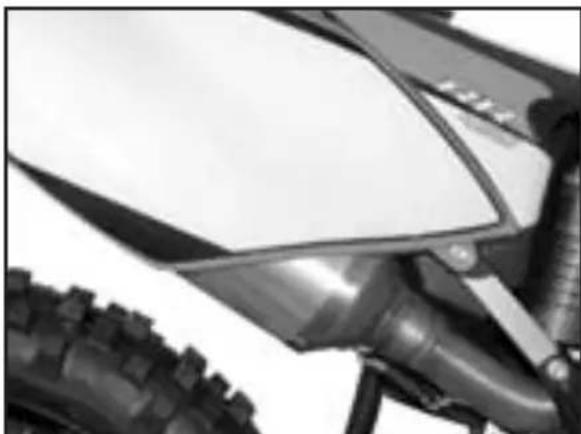
The catalytic converter
The catalytic converter is located at the end of the exhaust pipe and is part of the muffler, fixed to the exhaust pipe by spot welding in two places.
Its function is to reduce the harmful substances present in the exhaust fumes, specifically CO (carbon monoxide), the HC (unburned fuel) and the Nox (nitrogen oxide).
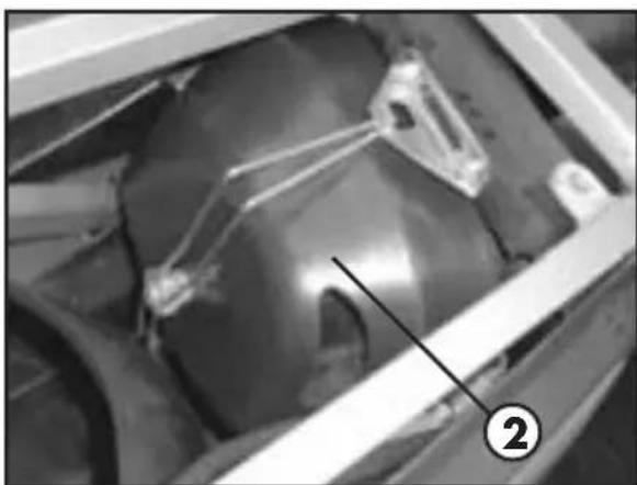
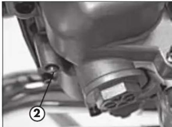
Soundproof shell
This last device 2 located above the air filter, has the function of reducing the emission of polluting gases and sound thus minimising noise pollution.
CONTENTS
CHAPTER 2 OPERATION
Checks to be performed before each ride
Recommended lubricants
Running-in
Starting the engine
Refuelling
CHECKS TO BE PERFORMED BEFORE EACH RIDE
The vehicle can be used only if it is in perfect condition from a technical point of view. To ensure maximum safety, it is advisable to carry out a general inspection of the motorcycle before each ride. The checks to be performed are described below.
1 CHECK THE ENGINE OIL LEVEL
Insufficient oil levels lead to early wear and, in the long run, to engine damage.
2 FUEL
Check the level of the fuel in the tank, arrange the breather pipe so that it has no kinks and fit the fuel tank cap.
3 DRIVE CHAIN
A slack chain can come out of the chainring and sprocket. An overtight chain can break or damage the other components of the final drive. A dirty or poorly lubricated chain can cause premature wear of the parts.
4 TYRES
Thoroughly check the tyre tread. If a tyre presents cuts or bulges, replace it. The thickness of the tread must be as prescribed by law. Check the tyre pressure.
Wear and unsuitable pressure adversely affect road holding.
5 BRAKES
Check the operation of the brakes and the level of the brake fluid. If the brake fluid level falls below the minimum, check the brake pads for wear and the braking system for possible leaks. If an oil leak is found, have the braking system overhauled by a specialized BETAMOTOR workshop.
6 CABLE CONTROLS
Check the adjustment and the operation of all the cable controls.
7 COOLANT
Check the level of the coolant when the engine is cold.
8 ELECTRICAL SYSTEM
With the engine running, check the operation of the headlight, the rear and brake lights, the indicators, the warning lights and the horn.
9 SPOKES
Check that the spokes are properly tightened.
1ONUTS AND BOLTS
Inspect all the nuts and bolts.
Note
Check the presence of the vehicle identification papers.
In cold weather, it is advisable to warm up the engine by letting it idle a few minutes before starting it off. Each time the vehicle is used cross-country, it is necessary to wash carefully, dry it and then lubricate.
RECOMMENDED LUBRICANTS
To maximize the vehicle's performance and ensure many years of trouble-free operation, we recommend using the following products:
| PRODUCT TYPE SPECIFICATION | NS |
| ENGINE OIL BARDAHL XTM15W 50 | W 50 |
| BRAKE OIL BARDAHL BRAKE FLUID DOT4 | |
| FORK OIL EB-H16 SAE 7,5 | |
| TIE ROD GREASE BARDAHL MPG2 | |
| CLUTCH OIL ARAL VITAM LS (mineral oil) | |
| LIQUID COOLANT IP ECOBLU |
Note
It is essential that all renewals should be performed with the products listed in the table above.
RUNNING-IN
The running-in period lasts approximately 15 hours, during which it is advisable to:
1 During the first 3 hours of operation the engine should only be used to approximately 50 percent of its power. In addition, the engine speed should not exceed 7,000 rpm.
2 For the next 12 hours of operation the engine should only be used to about 75 percent of its power.
3 Use the vehicle after properly warming up the engine.
4 Avoid travelling at constant speed (changing the speed causes the different components to bed in evenly and more quickly).
WARNING
After the first 3 hours or 20 litres of petrol change the engine oil.
- Always use high-octane unleaded petrol.
After using the vehicle on rough ground for the first time, carefully check the tightening of all nuts and bolts.
2
STARTING THE ENGINE
COLD STARTING
1 Open fuel cock 1.
2 Take the vehicle off the stand.
3 Shift into neutral.
4 Operate choke 3.
5 WITHOUT opening the throttle, firmly and FULLY operate kickstart 2 or use the electric starter.
HOT STARTING
1 Open fuel cock 1
2 Take the vehicle off the stand.
3 Shift into neutral.
4 WITHOUT opening the throttle, firmly and FULLY operate kickstart 2 or use the electric starter.

WHAT TO DO IF THE ENGINE IS FLOODED
After a fall, the engine may receive more fuel than is needed. Actuate the kickstart 5-10 times or press the electric starter button twice for 5 seconds. Subsequently start the engine as described previously. If necessary, remove the spark plug and dry it.
WARNING
The carburettor is equipped with an accelerating pump.
When starting the engine, do not open the throttle fully more than once as the engine might get flooded.
CHoke
When choke 3 is pulled out completely, a hole is opened in the carburettor through which the engine can suck in extra fuel. This makes it possible to obtain a rich fuel-air mixture suitable for cold starting. To deactivate the choke, push it in to its starting position.
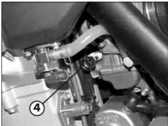
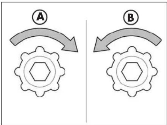
IDLING SETTING
The knob 4 on the carburettor can be used to the set the idle speed.
Turn the knob clockwise A to increase, turn the knob anticlockwise B to decrease.
2
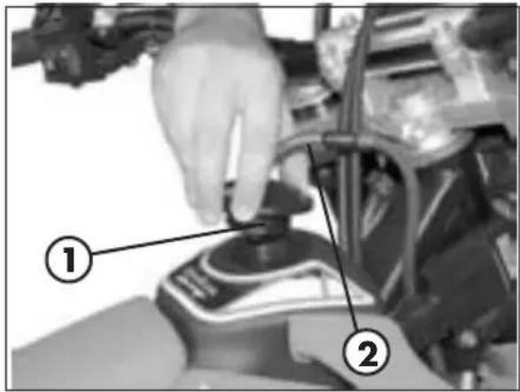
REFUELLING
FUEL TANK CAP
Open: Turn tank cap 1 anticlockwise.
Close: Replace the tank cap and turn it clockwise.
Arrange tank breather pipe 2 so that it forms no kinks.
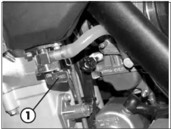
FUEL COCK
OFF Fuel cock 3 is closed.
ON Before using the vehicle, turn the knob to ON. This allows the fuel to flow to the carburettor. When the fuel cock is in the ON position the fuel tank empties until only the reserve fuel is left.
RES The reserve fuel is used only if the knob is in the RES position. Do not forget to bring the knob back to the ON position after refuelling.
Reserve fuel 1 litre
The fuel tank capacity is approximately 8 litres, including 1 litre reserve.
Immediately wipe off any fuel spills from the bodywork and other parts of the vehicle.
Stop the engine before refuelling.
Petrol is highly flammable. Take care not to spill it from the tank while refuelling.
Keep open flames and lighted cigarettes away from the tank filler: danger of fire.
Avoid inhaling harmful vapours.
Fuel expands under the action of heat. It is therefore recommended not to fill the tank to the brim.
CONTENTS
CHAPTER 3 CHECKS AND MAINTENANCE
Motor oil level check
Motor oil and oil filter substitution
Check the level of the front and rear brake fluid and bleeding
Check the front and rear brake pads
Check the oil level in the hydraulic clutch and bleeding
Fork oil
Air filter
Spark plug
Carburetor
Coolant
Removing the plastics
Drive chain maintenance and wear
Suspensions: telescopic fork and shock absorber
Charging the battery
Cleaning and checking the vehicle
Scheduled maintenance
Prolonged inactivity
3
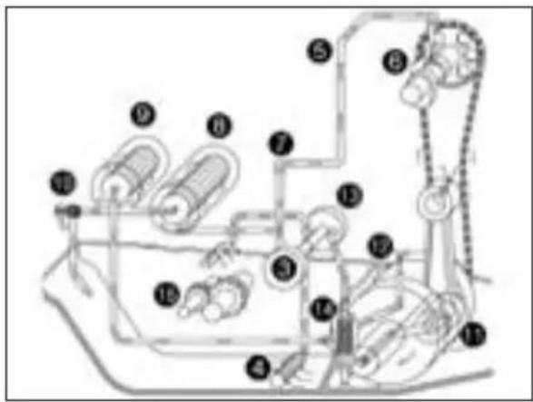
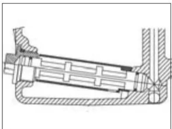
OIL CIRCUIT
Oil pump 3 sucks engine oil from the oil sump through long oil unit 4. Oil pipe 5 conveys the oil to the cylinder head up to camshaft lubrication point 6. The oil quantity is adjusted by means of oil passage screw 7. An oil pipe branches off towards long oil unit 8, where the coarser particles are filtered out. The oil then comes to short oil unit 9, which filters out the smaller particles. The filtered oil is then pumped through bypass valve 10 to small-end bearing 11 and sprayed from below through jet 12 onto the piston. A second oil pump 13 sucks oil from the crankcase through short oil unit 14 and lubricates gears 15.
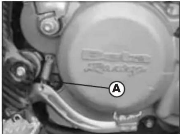
CHECKING THE ENGINE OIL LEVEL
The engine oil level can be checked when the engine is cold or hot. Place the vehicle in an upright position (not on the side stand) on level ground. When the engine is cold, the oil should reach the lower edge of sight A. When the engine is hot, the oil should reach the upper edge of the sight. Top up as necessary.
WARNING
The use of insufficient quantities of oil or of oil of inferior quality results in premature wear of the engine.
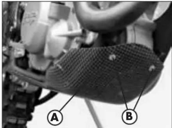
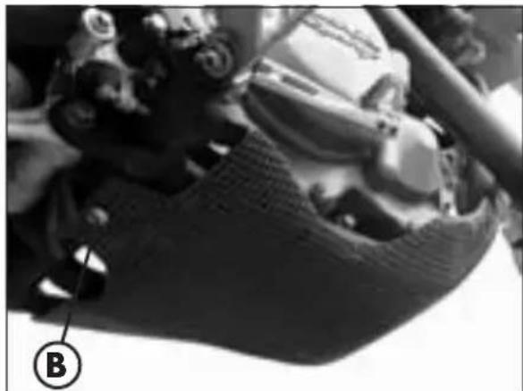
CHANGING THE ENGINE OIL AND THE OIL FILTER
Before performing this operation, if lower bumper A is present, remove it after unscrewing the three screws B as shown in the figure.
Whenever the oil is changed, the long and short oil units need to be cleaned and both oil filters replaced.
The oil must be changed when the engine is at operating temperature.
WARNING
When at operating temperature, the engine and the oil it contains are very hot. Take special care to avoid burns.
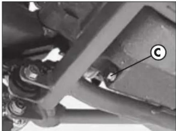
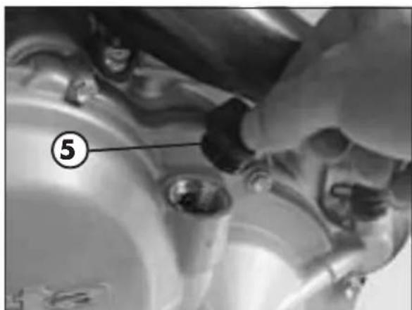
Park the motorcycle on level ground, remove screw C and let the oil drain in a container.
Thoroughly clean the screw (with a magnet). After the oil has drained completely, clean the sealing surface, replace screw C with the seal ring and tighten at 20Nm
3
CHECKS AND MAINTENANCE
CLEANING THE SHORT OIL UNIT
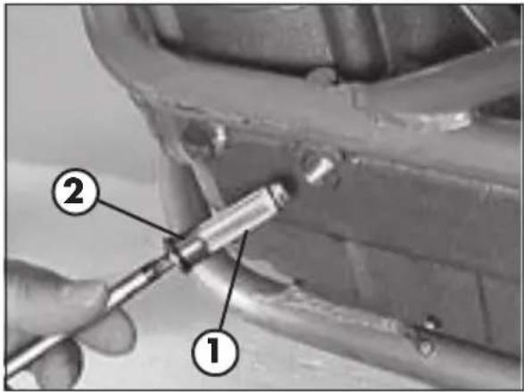
Short oil unit 1 is inserted in Allen screw 2 on the lower side of the engine. Insert an Allen wrench into the screw socket and loosen the oil drain screw.
Remove the oil unit, thoroughly clean its components and blow them with low-pressure compressed air. Check the O-rings for damage and if necessary replace them.
Replace the oil unit with the screw and tighten the screw at 10 Nm.
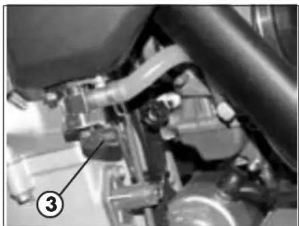
CLEANING THE LONG OIL UNIT
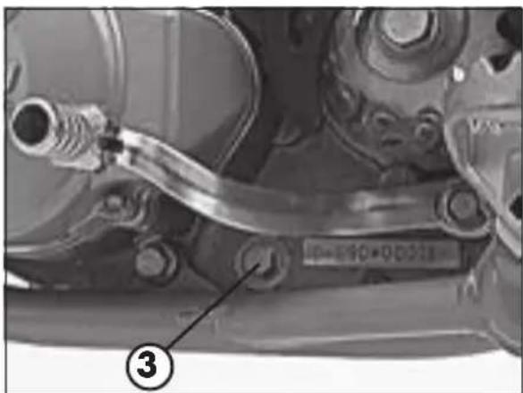
The long oil unit is inserted in hexagonal head screw 3 next to the engine serial number. Remove the screw with the oil unit, thoroughly clean the components and blow them with low-pressure compressed air. Check the O-rings for damage and if necessary replace them.
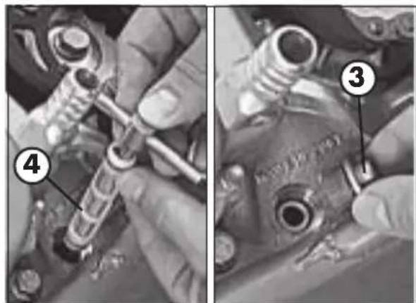
To replace long oil unit 4, use a 300mm spanner as shown in the figure, then insert the spanner through the opening in the hole on the opposite side of the crankcase. Push the oil unit in the crankshaft until it stops and then remove the spanner. Replace screw 3 and tighten at 15Nm .
The oil unit is fitted in a tilted position (see diagram). To avoid malfunctions, be sure to observe this position.
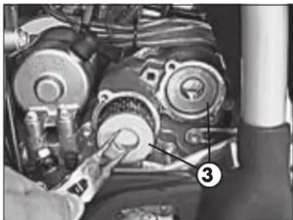
REPLACING THE OIL FILTER
Remove screw 1 and allow the oil to drain into a container placed under the engine. Remove the four screws 2 and take off the two oil filter covers.
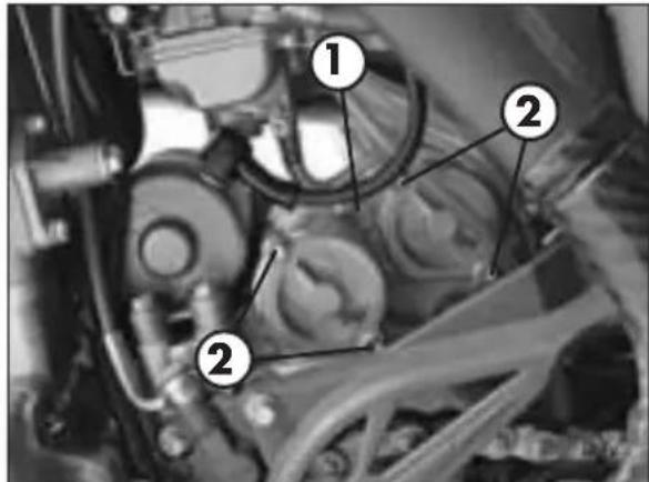
Using special seeger ring pliers, pull the two filter elements 3 out of the crankcase. Clean the oil filter covers, the sealing surfaces of the O-rings and the crankcase. Check the oil filter cover O-rings for damage and if necessary replace them.
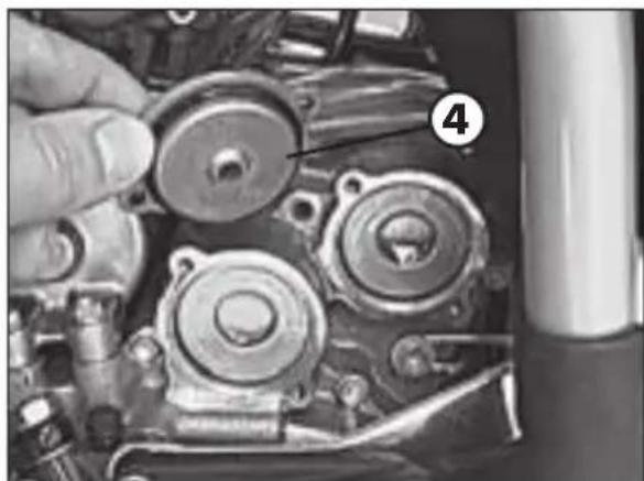
Insert the long filter unit at the front and the short filter unit at the back of the crankcase. Grease the oil filter cover O-rings and fit covers 4. Fit screws 2 and tighten them at 6 Nm. Tighten screw 1 at 8 Nm.
Remove screw fastener 5 from the clutch cover and pour in 1.25 litres of fully synthetic engine oil (MOTOREX COBRA 15W40).
WARNING
Before starting the engine, it is advisable to rotate the engine (using the kickstart) to allow the oil to spread evenly throughout the system.
Start the engine and check the tightening of all the screw fasteners and of the oil filter covers.
Finally check the engine oil level and if necessary top up.
3
CHECKS AND MAINTENANCE

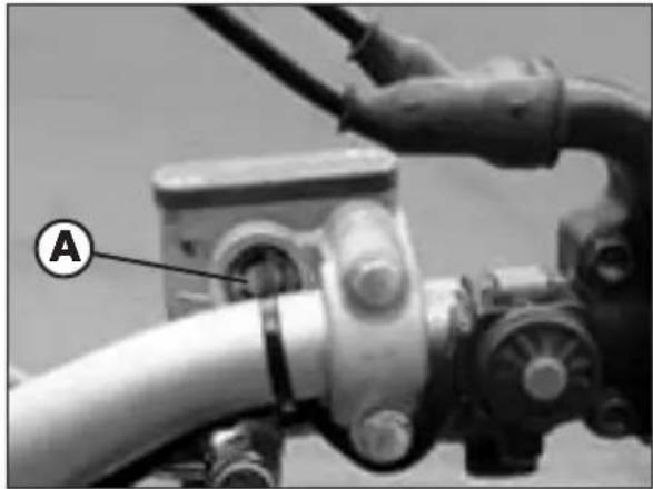
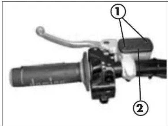
Check the level of the brake fluid through sight A. The level of the fluid should never fall below the mark in the sight.
To restore the level of the brake fluid, loosen the two screws 1, lift cap 2 and add brake fluid (IP DOT 4) until its level is 5mm below the upper rim of the reservoir.
WARNING
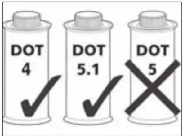
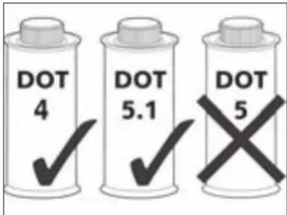
We recommend using DOT 4 brake fluid. Should this fluid be unavailable, use DOT 5.1 fluid instead. Do not on any account use DOT 5 brake fluid. This is a purple fluid with a base of silicone oil which requires special seals and tubes.
WARNING
The brake fluid is extremely corrosive. Take care not to spill it on the paintwork.
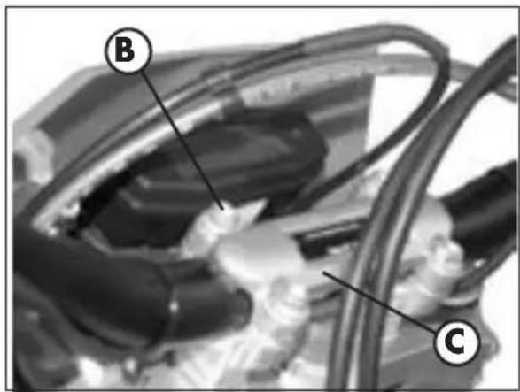
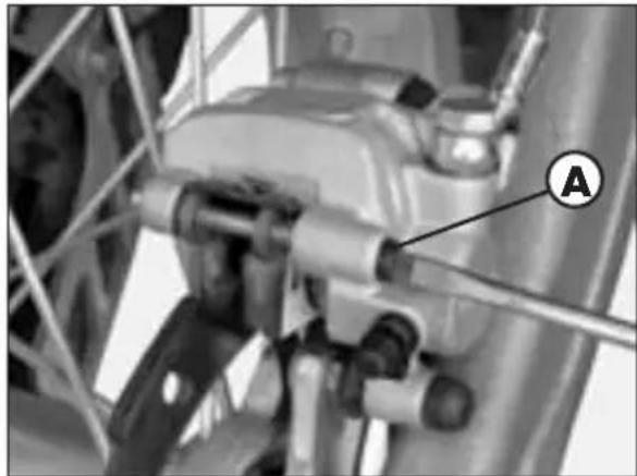
BLEEDING THE FRONT BRAKE
Follow these steps to bleed the front brake circuit:
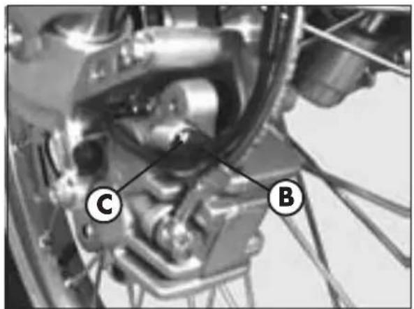
- Remove rubber cap B from valve C.
- Remove the oil reservoir cap.
Insert one end of a small tube into valve C and place the other end in a container. - Unscrew valve B (while pulling the brake lever) and then pump by repeatedly actuating the brake lever until oil starts flowing out continuously with no air bubbles. During this operation, it is important that the lever should not be released completely and that the brake pump reservoir should be continuously refilled to make up for the oil that is flowing out.
- Tighten the valve and extract the tube.
Replace the cap. - Replace the fluid reservoir cap on the brake pump.
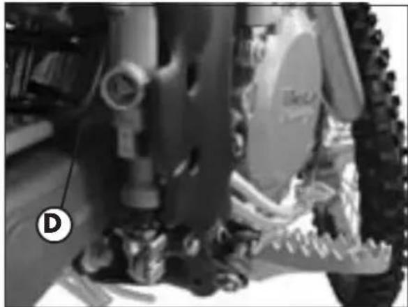
Check the level of the brake fluid through sight D. The level of the fluid should never fall below the mark in the sight.
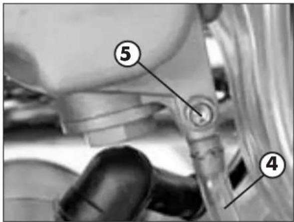
RESTORING THE LEVEL OF THE REAR BRAKE FLUID
To restore the level of the brake fluid, unscrew cap 3 and pour in brake fluid (IP DOT 4) until the level reaches the mark in sight D.
WARNING
We recommend using DOT 4 brake fluid. Should this fluid be unavailable, use DOT 5.1 fluid instead. Do not on any account use DOT 5 brake fluid. This is a purple fluid with a base of silicone oil which requires special seals and tubes.
WARNING
The brake fluid is extremely corrosive. Take care not to spill it on the paintwork.
BLEEDING THE REAR BRAKE
Follow these steps to bleed the rear brake circuit:
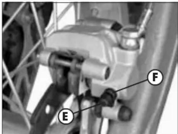
- Remove rubber cap E from valve F.
- Unscrew the brake fluid reservoir cap.
- Insert one end of a small tube into valve F and place the other end in a container.
- Unscrew valve F (while pulling the lever) and repeatedly operate the brake pedal until the fluid comes out smoothly with no air bubbles. During this operation, be sure to never release the pedal completely and keep pouring fresh fluid into the brake pump reservoir so as to replace the fluid that comes out.
- Tighten the valve and extract the tube.
- Replace the cap.
- Replace the screw cap on the brake pump.
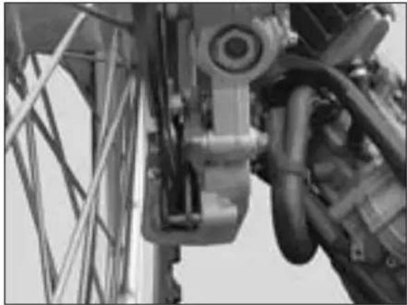
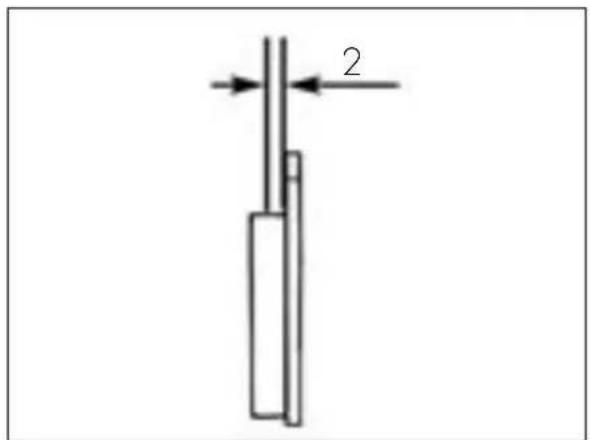
In order to verify the wear condition of front brake is enough to view the plincer from the bottom, where is possible to glimpse the brake lining tails which will have to show a brake of 2mm in thickness. If the stratum is lesser let's start replacing them.
Note
Perform the check according to the times shown in the table on page 134.
WARNING
Failure to promptly replace the brake pads can result in a considerable reduction of the braking action and in damage to the brake disc.
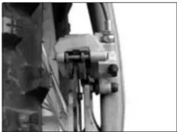
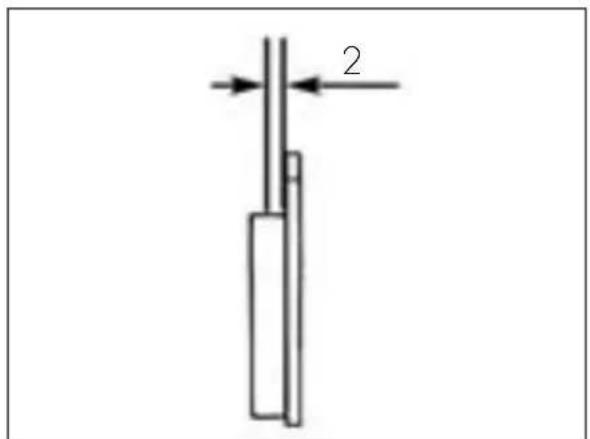
In order to verify the wear condition of rear brake is enough to view the plincer from the back side, where is possible to glimpse the brake lining tails which will have to show a brake of 2mm in thickness. If the stratum is lesser let's start replacing them.
Note
Perform the check according to the times shown in the table on page 134.
WARNING
Failure to promptly replace the brake pads can result in a considerable reduction of the braking action and in damage to the brake disc.
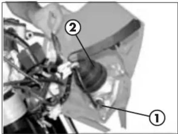
CHECKING THE OIL LEVEL IN THE HYDRAULIC CLUTCH
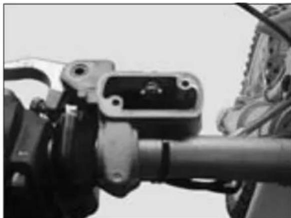
To check the oil level in the clutch pump, first remove cover 2.
Remove the two screws 1 and take off cover 2 together with the rubber bellows.
With the clutch pump in a horizontal position, the level of the oil should be 4mm below the upper rim.
If necessary top up with ARAL VITAM LS hydraulic oil, which is available from your BETAMOTOR dealer.
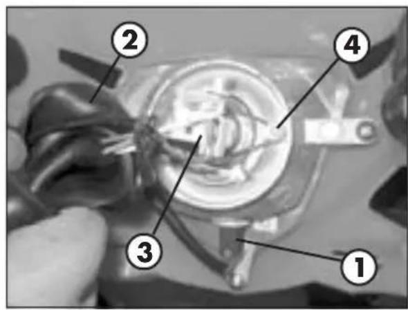
BLEEDING THE HYDRAULIC CLUTCH
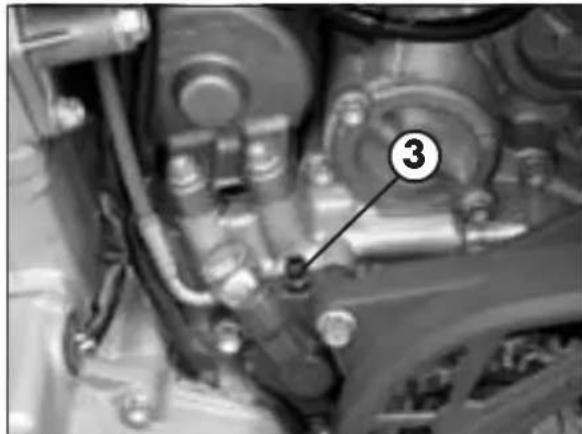
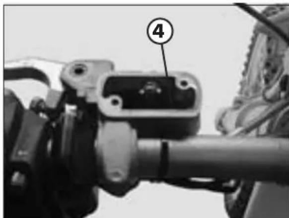
To bleed the hydraulic clutch, first remove the clutch pump cover. To do this, remove the two screws 1 and take off cover 2 together with the rubber bellows. Remove the breather valve from clutch pump cylinder 3. Fit the bleed syringe filled with SAE 10 hydraulic oil in the breather valve socket. Pump in oil until it comes out of clutch pump hole 4 with no air bubbles. Ensure that no oil overflows. The bleed syringe is available from BETAMOTOR dealers. Once the bleeding is complete, check the oil level in the clutch control cylinder.
If necessary top up with ARAL VITAM LS hydraulic oil, which is also available from your BETAMOTOR dealer.
3
FORK OIL
Right/left-hand rod
The procedure for changing the oil in the forks is provided only for information. We recommend having the operation performed by a BETAMOTOR authorized workshop.
- Remove the handlebars after unscrewing the four screws B fixing clevis C.
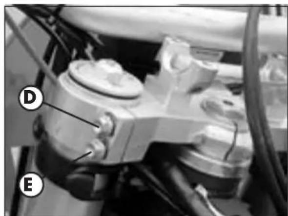
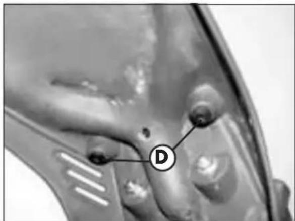
- Unloosen the stem clamping screws D and E.
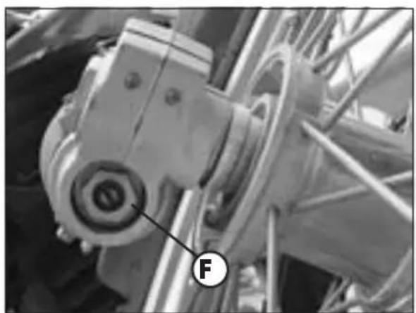
-
Remove lower plug F and upper plug A (pay attention to the spring).
-
Let all the oil drain from the rod.
-Replace fork lower plug F.
- Pour in fresh oil of the type shown in the table on page 105.
- Fit and tighten upper plug A.
- Tighten in sequence, first the D screw, then the E screw and aging the D screw.
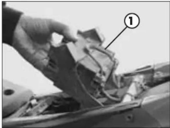
AIR FILTER
A dirty air filter hinders the passage of air, reduces engine power and increases fuel consumption. For these reasons it is essential to clean the air filter on a regular basis.
Follow these steps to gain access to the air filter.
- Remove the saddle.
- Lift and rotate battery 1 (see figure).
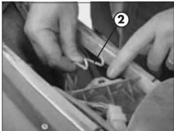
- Release filter fastener 2
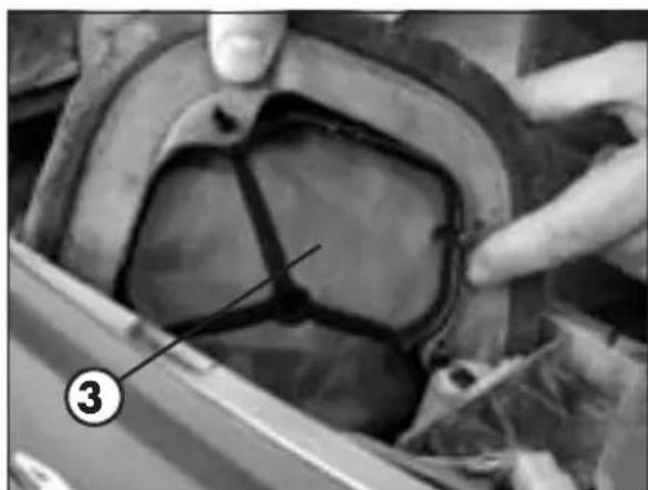
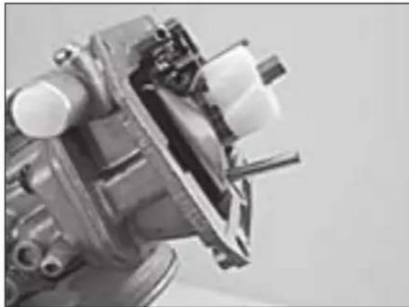
Soundproof shell removal - Pull out air filter 3.
- Carefully wash the filter with soap (or special detergent) and water.
- Dry the filter.
Wet the filter with filter oil and then remove the excess oil to prevent it from dripping.
WARNING
To avoid corroding the filter, do not clean it in foam containing petrol or petroleum. Never use the vehicle if the air filter is not in place. The infiltration of dust and dirt can cause damage and considerable wear.
If necessary clean the inside of the filter box.
- Replace the filter taking special care to ensure the seal of the rubber gasket.
- Attach filter fastener 2.
WARNING:
After each operation check that no object is left in the filter box.
Clean the filter every time the vehicle is used over rough ground.
SPARK PLUG
Keeping the spark plug in good condition makes for reduced consumption and optimum engine performance.
It is advisable to remove the spark plug when the engine is hot (and naturally off) because the carbon formation and the colour of the insulator provide important information on carburetion, lubrication, and the general condition of the engine.
Note
Black spark plug = mixture is rich
Light brown spark plug = mixture is correct
White spark plug = mixture is lean
This operation must be performed with the utmost care to avoid severe hand burns.
Always wear protective gloves.
To carry out the check, simply remove the current cap and then unscrew the spark plug using the spanner provided.
Carefully clean the electrodes using a wire brush. Blow the spark plug with compressed air to prevent any residues from getting into the engine.
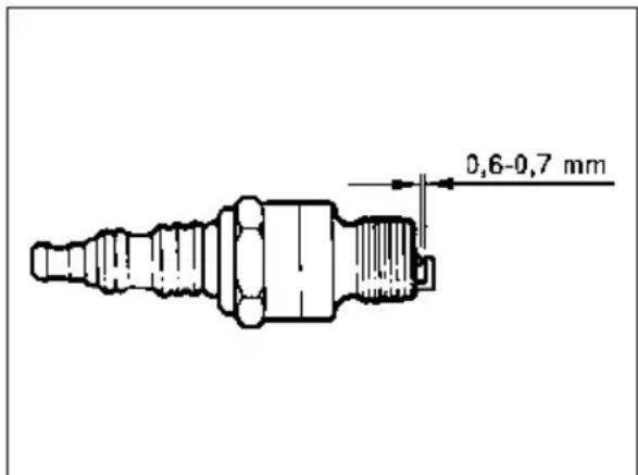
Measure the spark gap with a thickness gauge. The gap should be 0.6 - 0.7mm . If the gap is not as specified, restore the proper gap by bending the earth electrode.
Check that the insulator is not cracked and that the electrodes are not corroded, in which case the spark plug should be immediately replaced.
Conduct the check by referring to the table on page 134.
Lubricate the spark plug thread, and then (when the engine is cold) screw in the spark plug by hand to its abutting end. Finally tighten the spark plug with the spanner.
Note:
- Always use NGK DCPR 8 E spark plugs.
CARBURETTOR - ADJUSTING THE IDLE SPEED
Engine starting is strongly affected by the idle speed adjustment. In other words, an engine whose slow running is properly adjusted is easier to start than an engine with an unsuitably tuned up engine.
The idle speed is adjusted by means of adjusting wheel 1 and mixture adjusting screw 2. The adjusting wheel regulates the idling mixture, which reaches the engine through the idling system. Rotating the wheel clockwise decreases the quantity of fuel (lean mixture); rotating it anticlockwise increases the quantity of fuel (rich mixture).
To properly adjust the idle speed, follow these steps:
- Turn in mixture adjusting screw 2 until it stops, then turn it until you obtain the basic adjustment recommended by BETAMOTOR (see engine specifications on page 96).
Warm up the engine. - Turn adjusting wheel 1 to obtain the standard idle speed (1400-1500 rpm).
- Slowly turn mixture adjusting screw 2 clockwise until the idle speed begins to lower. Remember this position, then slowly turn the mixture adjusting screw anticlockwise until the engine speed lowers again. Determine the point between the two positions where the highest idle speed is obtained. Should the engine speed increase considerably, decrease the engine speed to the standard level and repeat the above procedure. If you make a markedly sporting use of your vehicle, which increases the heating of the engine, choose a leaner mixture by turning the adjusting screw approximately 1/4 of a turn clockwise from the ideal setting.
NOTE
Failure to successfully complete the above procedure can be the result of an improperly sized idling jet.
a) If the mixture adjusting screw is turned until it stops and no changes in the idle speed are observed, a smaller idling jet is required.
b) If the engine stalls when the adjusting screw is still two turns open, a larger idling jet is needed.
Naturally, after replacing the jet the adjusting procedure will have to be restarted from the beginning.
- Turn the adjusting wheel until you obtain the desired idle speed.
- The idle speed will have to be adjusted again in case of marked changes in the outside temperature and riding altitude.
CARBURETTOR WEAR GUIDELINES
The throttle valve, the needle valve and the needle jet are subject to heavy wear due to engine vibrations.
This can result in carburettor malfunctions (e.g. mixture enrichment).
CHECKING THE FLOAT LEVEL (float height)
Remove the carburettor and the float chamber. Tilt the carburettor so that the float touches the float needle valve without pressing it too hard.
In this position the float edge should be parallel with the float chamber sealing surface (see figure).
If the float height does not correspond to the nominal value, check the float needle valve and if necessary replace it.
If the needle valve is in working order, adjust the float height by bending float lever 3.
Fit the float chamber, install the carburettor and adjust the idle speed.
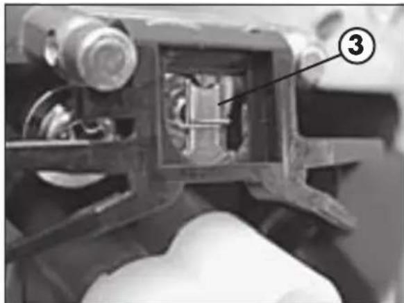
DRAINING THE CARBURETTOR FLOAT CHAMBER
The carburettor float chamber can be drained by following the procedure described below while the engine is cold. Close the fuel cock and place tube 4 in a container to gather the fuel that flows out. Open drain screw 5 and drain the fuel. Close the drain screw, open the fuel cock and check the seal of the system.
WARNING
Fuel is flammable and toxic and must be handled with great care. Never work on the fuel system near heat sources or open flames. Always allow the engine to cool down before working on the fuel system. Wipe off any excess fuel with a rag. Materials soaked in fuel are also flammable. In case of ingestion or contact with sensitive parts of the body immediately seek medical attention. Fuel is to be disposed of as prescribed by law.
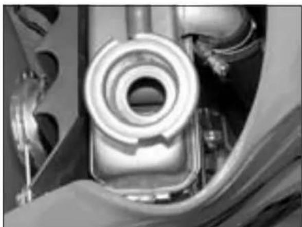
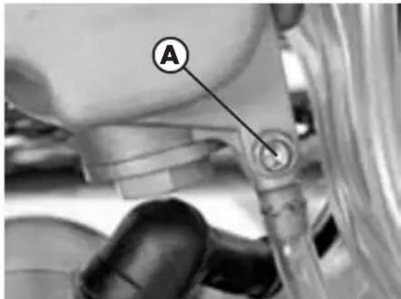
COOLANT
The level of the coolant must be checked when the engine is cold. Use the following procedure:
- Unscrew cap A and visually check the level of the liquid. When the engine is cold, the radiator fins should be immersed in the liquid for about 10 mm.
- Top up if the coolant does not cover the radiator fins (see chart on page 105).
The capacity of the circuit is shown in the table on page 95.
WARNING
To avoid scalds, never unscrew the radiator filler cap when the engine is hot.
REMOVING THE PLASTICS
To facilitate checks and operations in certain areas of the vehicle, it is essential to remove the bodywork sections as described below.
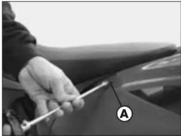
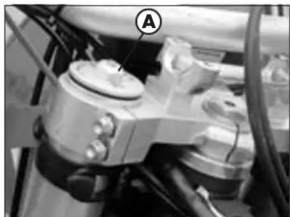
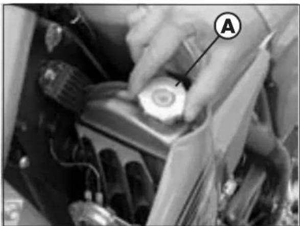
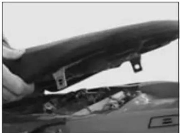
Removing the saddle
Remove the two fixing screws A (one on each side), lift the saddle as shown in the figure and pull it off from the back of the vehicle.
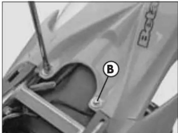
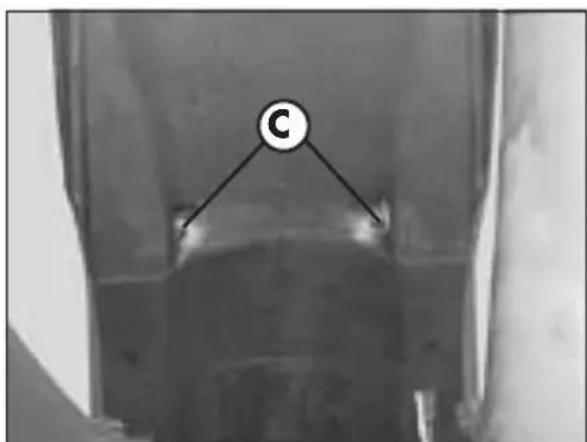
Removing the rear mudguard
Remove the two fixing screws B and then the two fixing screws C and D from under the rear mudguard.
3
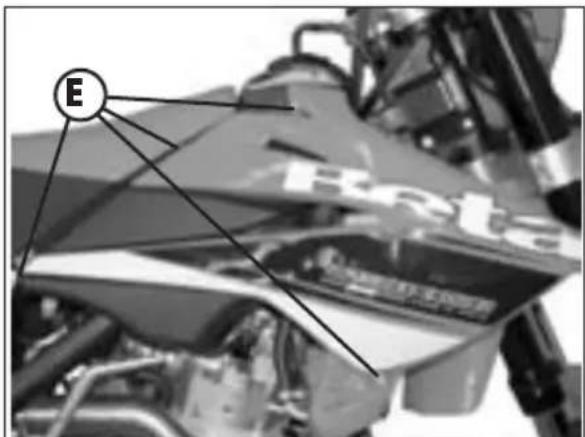
Removing the front side panels Unscrew the eight fixing screws E (four on each side) and remove the panels.
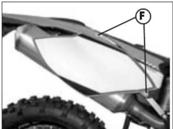
Removing the rear side panels Unscrew the four fixing screws F (two on each side) and remove the panels. The upper screw fixes the saddle as well as the rear panel.
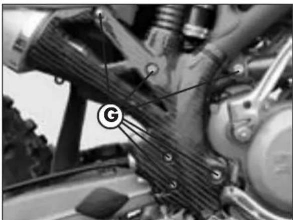
Removing the right-hand side bumper
Unscrew the six fixing screws G, remove the plastic strap and take off the side bumper (if present).
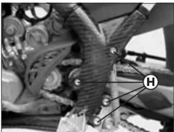
Removing the left-hand side bumper Unscrew the four fixing screws H,remove the two plastic straps and take off the side bumper (if present).
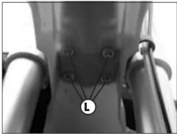
Removing the front mudguard Remove the four screws L from underneath the front mudguard.
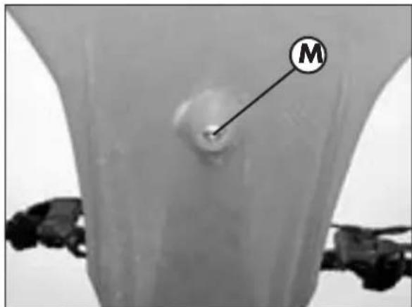
Remove screw M (also located under the mudguard) fixing the mudguard backing plate.
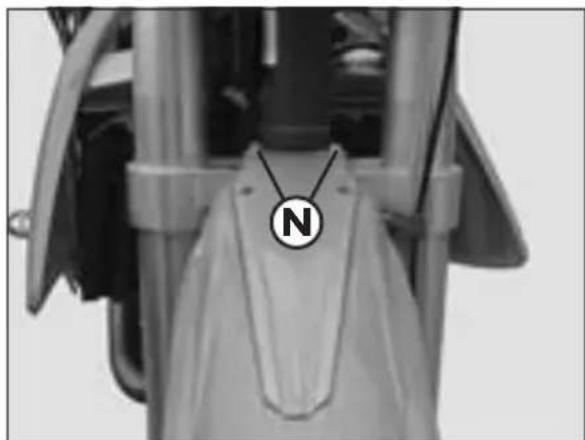
Remove the two mudguard backing fixing screws N from the top of the backing plate.
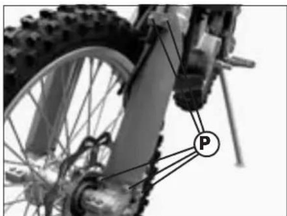
Removing the fork covers Unscrew the eight fixing screws P (five on the left side and three on the right side) and take off the fork covers.
3
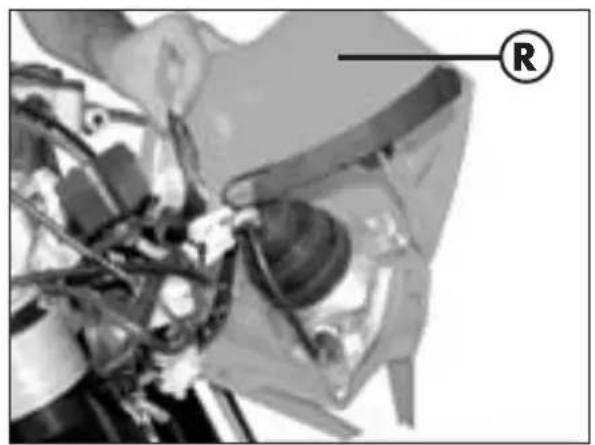
Removing the headlight fairing Release the two rubber bands as shown in the figure, pull out the headlight insert and take off fairing R.
DRIVE CHAIN MAINTENANCE
The life of the drive chain largely depends on its maintenance. Chains without X-rings must be periodically cleaned in petroleum and then immersed in hot chain oil or treated with a chain spray.
X-ring chains require very little maintenance. The best way to clean them is rinsing them generously with water. Never use brushes or solvents to clean an X-ring chain. Once the chain has dried, you can use a chain spray specially designed for X-ring chains.
Take special care in preventing the lubricant from coming into contact with the rear tyre or brake disc, otherwise the tyre grip and the action of the brake would be greatly reduced, making it very difficult to control the vehicle.
DRIVE CHAIN WEAR
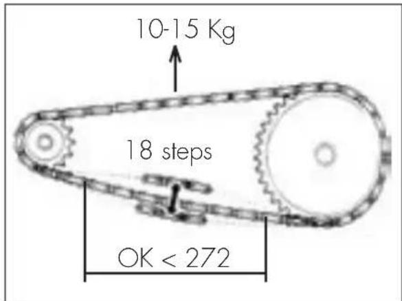
To check the wear of the drive chain use the procedure described below.
Shift into neutral, pull up the upper stretch of the chain with a force of 10-15 kg (see figure). Measure the length of 18 links on the lower stretch of the chain. If the length is ≥ 272mm , replace the chain. Chains do not always wear evenly. For this reason it is important that the measurement is taken at different points along the chain.
When fitting a new chain, be sure to replace the chainring and sprocket as well. New chains wear more quickly if fitted on old and worn sprockets. After replacing the chain, adjust its tension as described on page 141.
3
SUSPENSIONS
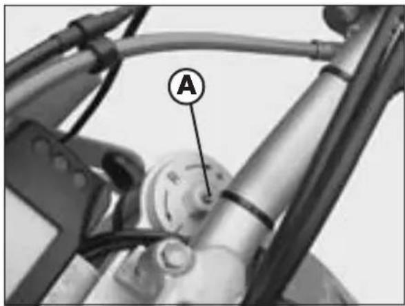
TELESCOPIC FORK
The hydraulic rebound damper determines the behaviour of the telescopic fork during extension and can be adjusted by means of screw A. Turning the screw clockwise (towards the + sign) increases the action of the rebound damper; turning it anticlockwise (towards the - sign) decreases the action of the rebound damper.
Standard adjustment:
12 clicks from the completely closed position
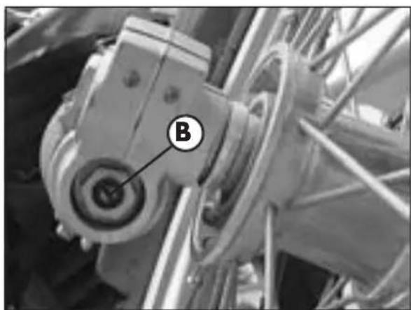
The hydraulic compression damper determines the behaviour of the telescopic fork during compression and can be adjusted by means of screw B located at the lower end of the fork legs. Turning the screw clockwise increases the action of the compression damper; turning it anticlockwise decreases the action of the compression damper.
Standard adjustment:
12 clicks from the completely closed position
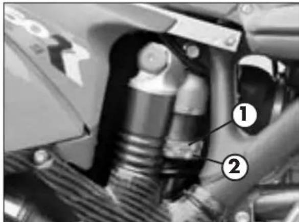
SHOCK ABSORBER
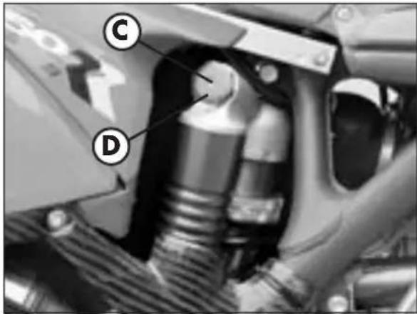
ADJUSTING THE HYDRAULIC COMPRESSION DAMPER (high and low speeds)
The shock absorber can be adjusted for both high and low speeds.
The terms 'high' and 'low' refer to the compression speed of the shock absorber, not to the speed of the vehicle.
The low-speed adjustment affects the behaviour of the shock absorber during low-speed compression; conversely the high-speed adjustment affects its behaviour during high-speed compression.
Low-speed adjustment
- Using a screwdriver, loosen screw C by turning it clockwise to decrease the hydraulic compression damper.
Standard adjustment:
Screw completely open, 21/21 clicks
High-speed adjustment
- Turn knob D anticlockwise to decrease the hydraulic compression damper.
Standard adjustment
Knob completely open, 24/24 clicks
WARNING
Starting from the standard position, turn the knob anticlockwise (with a closing action). The central screw will move along with the knob. This is normal, as the screw will be in completely open position anyway.
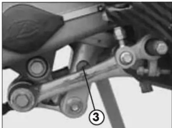
ADJUSTING THE SPRING PRELOAD
To adjust the spring preload, use the procedure described below.
Loosen countering 1. Rotate ring 2 clockwise to increase the spring preload (and consequently the shock absorber preload) or anticlockwise to decrease it.
After obtaining the desired preload, turn counterring 1 until it stops against adjusting ring 2.
Spring preload: 260 mm
ADJUSTING THE HYDRAULIC REBOUND DAMPER
Turn screw 3 to adjust the hydraulic rebound damper.
Tuming the screw anticlockwise (out) decreases the damping effect.
Standard adjustment:
25 clicks from the completely closed position
3
CHARGING THE BATTERY
Remove the battery and check its charge. Using an open-circuit multimeter (10-12 hours after the activation), check that the voltage is greater than 12.6V . If it is lower, it is advisable to recharge the battery. Based on the type of charger available, charge the battery using either of the following procedures:
- Constant voltage (14.4-15 V) - Charge the battery for about 12 hours. Check the voltage 10-12 hours after the end of recharge as described above.
- Constant current: Charge battery at 0.5-0.8 A until the voltage between the terminals stabilizes at 14.5V .
WARNING
The battery is sealed. When recharging it, do not remove the seal nor add any liquid.
WARNING
When recharging, first connect the battery to the battery charger and then turn on the charger.
If the battery is charged in a closed room, take care to ensure proper ventilation as during the charge the battery produces explosive gases.
CLEANING AND CHECKING THE VEHICLE
Use water jet to soften the dirt and mud accumulated on the paintwork, then remove them with a soft bodywork sponge soaked in water and shampoo (2-4 percent shampoo in water). Subsequently rinse well with water, and dry with air and cloth or suede leather. For the outside of the engine use a brush soaked in petroleum and clean rags. Petroleum damages the paintwork. Always wash the vehicle before waxing it with silicon waxes.
Important:
When cleaning using a high-pressure water jet cleaner, avoid aiming the jet to the digital instrument panel.

Detergents pollute water. Always wash the vehicle in areas equipped for collection and purification of the washing liquids.

Never wash the vehicle in the sun, particularly during the summer when the bodywork is hot. The shampoo would dry before being rinsed off and cause damage to the paintwork. Do not clean the plastic surfaces with cloths soaked in petrol or naphtha as they would lose their shine and mechanical properties.
CHECKS AFTER CLEANING
After cleaning the motorcycle, it is advisable to:
- Clean the air filter (refer to the procedure described on page 119).
- Empty the fuel container by loosening the fuel emptying screw in order (as described on page 124) to check for the presence of water.
- Add grease to the chain.
SCHEDULED MAINTENANCE
| Item\Interval | hour (h) 3 fuel (litre) 20 | after/every 15 100 | |
| Air filter (after off-road use) P P | |||
| Valves I I | |||
| Spark plug (replace every 30 hours) - I | |||
| Idle speed I I | |||
| Throttle cable play I I | |||
| Clutch I I | |||
| Engine oil S S | |||
| Engine oil filter S S | |||
| Motor oil net filter | P P | ||
| Exhaust pipe bolts | - | T | |
| Brakes | I I | ||
| Brake lines (replace every 4 years) | I I | ||
| Brake fluid (replace every 2 years) | I I | ||
| Tyres | - | I | |
| Steering | I I | ||
| Fork | - I | ||
| Rear suspension | - I | ||
| Frame nuts / bolts and oil tubes | T T | ||
| Chain tension | I I |
l = Check and if necessary adjust, clean, lubricate or replace.
P = C l e a n
S = Replace/renew
T = T i g h t e n
Note:
For any service requirements, please contact Betamotor's Authorized Service Network.
PROLONGED INACTIVITY
A few simple operations should be performed to keep the vehicle in good condition whenever it is to remain inactive for a long period (e.g. during the winter):
- Thoroughly clean the vehicle.
- Reduce the tyre pressures by approximately 30 percent, and if possible raise the tyres off the ground.
- Remove the spark plug and pour a few drops of engine oil into the spark plug hole. Make the engine turn a few times by operating the kick-start (where available) and then replace the spark plug.
- Cover the unpainted parts, excepting the brakes and the rubber parts, with a film of oil or spray silicone.
- Remove the battery and keep it in a dry place. Charge the battery every 15 days.
-
Protect the vehicle with a dust cover.
-
Drain the carburetor float chamber by loosening screw A. The fuel drained from the chamber through a suitable pipe must be collected in a container and poured into the fuel tank. Do not dispose of the fuel in the environment.
-
Ret fighten the screw.
AFTER PROLONGED INACTIVITY
- Reinstall the battery.
- Restore the tyre inflating pressures.
- Check the tightening of all the screws having an important mechanical function.
Note:
Periodically check the tightening of the screws.
- Start the vehicle for the first time by means of the kick-start
CONTENTS
CHAPTER 4 ADJUSTMENTS
Brake adjustment: front lever and brake pedal
Adjusting the decompressor lever control cable
Adjusting the home position of the clutch lever
Adjusting the handlebars
Adjusting the throttle control cable
Checking and adjusting the steering play
Tensioning the chain
Adjusting the headlight
4
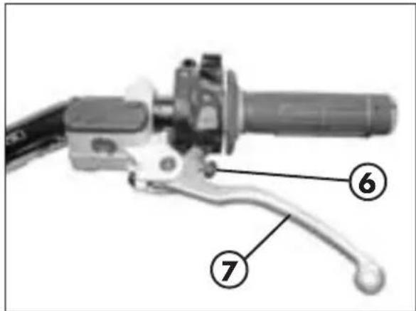
The home position of brake lever 2 can be adjusted by means of screw 1.
The home position of brake pedal 3 can be altered by turning adjusting screw 5 after loosening the counternut located under dust cap 4. Loosen the counternut and turn the adjusting screw until the desired height is obtained. Retighten the counternut after completing the operation.
The idle travel of clutch lever 7 can be adjusted by means of screw 6.
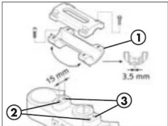
ADJUSTING THE HANDLEBARS
The handlebars can be fastened in one of four positions.
Lower clevis 1 can be positioned on holes 2 and 3 respectively and can be rotated 180 degrees to allow four different adjustments capable of suiting different driver's requirements.
Note:
The fuor positions make it possible to move the handle-bar axis as to the vertical axis of the steering-wheel
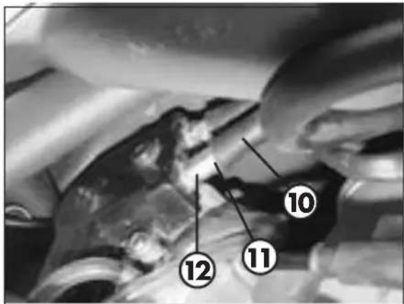
ADJUSTING THE THROTTLE CONTROL CABLE
The throttle control cable should always have a 3-5 mm play. In addition, the idle speed should not change when the handlebars are fully rotated to the left or right. Push back protective cap 10. Loosen counternut 11 and turn adjusting screw 12. Turning the screw anticlockwise decreases the idle travel; turning it clockwise increases it. Tighten the counternut and check that the throttle twist grip turns smoothly.
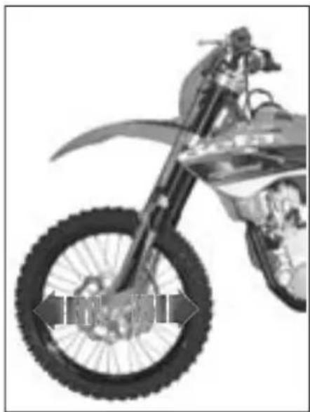
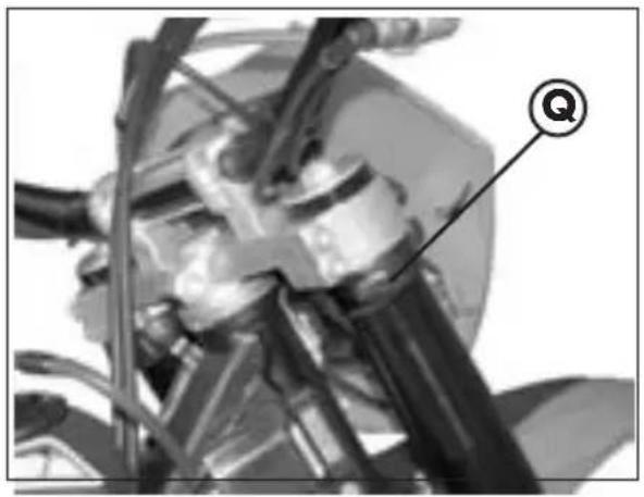
CHECKING AND ADJUSTING THE STEERING PLAY
Periodically check the play of the steering head tube by moving the forks backwards and forwards as shown in the figure. If any play is felt, carry out the adjustment by following these steps:
- Unscrew the five screws 13.
- Pull out the handlebars paying special attention to the clevises.
Loosen nut 14 - Reduce the play by turning ring Torefit the parts, follow the reverse procedure.
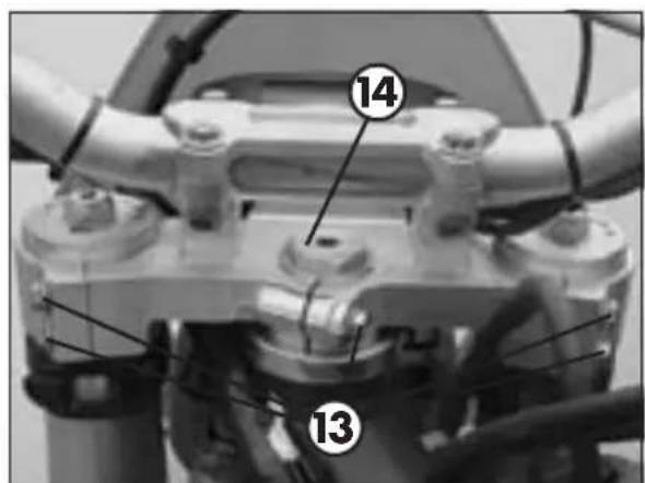
Note: Proper adjustment must leave no play and cause no stiffness, and allow the steering to rotate smoothly. Check the fitting direction of the clevises as it can alter the geometry of the handlebar.
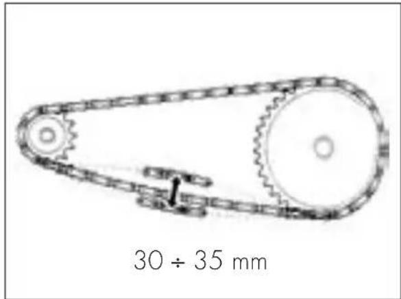
TENSIONING THE CHAIN
To ensure the drive chain a longer life, it is advisable to periodically check its tension. Always maintain the chain clean and lubricated.
If the chain play exceeds 30 ÷ 35 ~mm , tension the chain by following these steps:
-
Loosen wheel spindle nut 1.
-
Loosen counternuts A on either side of the fork.
-
Turn adjusting screws B on either side until the desired chain tension is obtained.
-
Tighten counternuts A on either side of the fork.
-
Tighten nut 1.

4
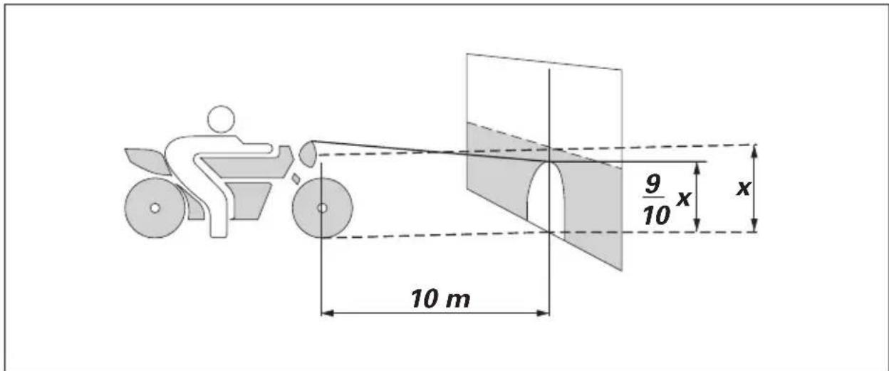
ADJUSTING THE HEADLIGHT
- The light beam is adjusted manually by turning the headlight fixing screws on the headlight fairing.
- Periodically check the direction of the beam. The beam can only be adjusted vertically.
- Place the vehicle on level ground (but not on the stand) 10 metres from a vertical wall.
- Measure the height of the headlight centre above the ground and then draw a cross on the wall at 9/10 of the height of the headlight centre.
- Turn on the low beam, get on the motorbike and check that the headlight beam on the wall is slightly lower than the cross drawn previously.
CONTENTS
CHAPTER 5 REPLACEMENTS
Replacing the brake pads: front and rear
Replacing the headlight bulbs
Replacing the rear light bulb
Replacing the exhaust-pipe
5
REPLACING THE BRAKE PADS
The procedure for replacing the brake pads is provided only for information. We recommend having the operation performed by a BETAMOTOR authorized workshop.
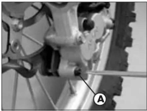
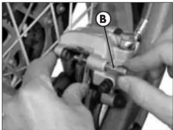
FRONT
Follow these steps to replace the pads:
- Push the brake caliper towards the disc so that the pistons reach their home positions.
- Unscrew dowel A.
Pull out pin B while supporting the two pads as shown in the figure. - Remove the brake pads taking care not to drop the leaf spring located under the pads.
- To reassemble, follow the reverse procedure. When fitting the pads, ensure that the leaf spring is properly in place.
WARNING
The brake disc must always be kept free from oil and grease. An oily or greasy disc strongly reduces the braking action.
After work has been carried out on the braking system, pull the brake lever to bring the pads into contact with the disc. This will allow the correct pressure point to be restored, thus ensuring proper operation of the braking system.
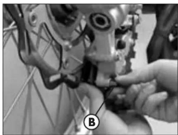
REAR
Follow these steps to replace the pads:
- Push the brake caliper towards the disc so that the pistons reach their home positions.
- Unscrew dowel A.
Pull out pin B while supporting the two pads as shown in the figure. - Remove the brake pads taking care not to drop the leaf spring located above the two pads.
- To reassemble, follow the reverse procedure. When fitting the pads, ensure that the leaf spring is properly in place.
WARNING
The brake disc must always be kept free from oil and grease. An oily or greasy disc strongly reduces the braking action.
After work has been carried out on the braking system, pull the brake lever to bring the pads into contact with the disc. This will allow the correct pressure point to be restored, thus ensuring proper operation of the braking system.
5
REPLACEMENTS
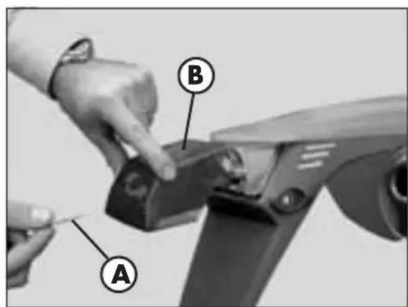
REPLACING THE HEADLIGHT BULBS
Release both spring washers and move forward the lamp holder front cowl.
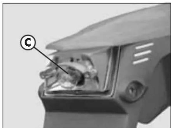
Carefully remove the tail light bulb together with lamp holder 1 from the parabola. Lift the rubber cover 2, release connector 3 and undo the screw 4. Lift the lamp holder parabola and replace the light bulb with a new one. Be careful not to touch the bulb so as not to compromise its efficiency.
Torefit, follow the procedure above but in reverse order.
When necessary, in order to replace the tail light bulb, simply slide it off the lamp holder and slide in a new one.
Fasten the lamp holder front cowl to the supporting pins and fix it with the two elastics.
REPLACING THE REAR LIGHT BULB
To replace the brake light bulb, follow these steps:
- Remove the two fixing screws A and lens B.
-Replace faulty bulb C.
- Refit lens B and fasten it with the two fixing screws A.
The bulbs have bayonet bases. To remove them, press them lightly, rotate them 30^ anticlockwise and then extract them.
REPLACING THE EXHAUST-PIPE
The description of the exhaust-pipe substitution is purely informative; actually is advisable to turn to a BETAMOTOR shop in order to make this.
As for substitution you must proceed in the following way:
- Put the motor-cycle on the stand under the motor
- Remove the saddle (vedi pag. 125)
- Remove the right and the left lateral bumper (vedi pag. 126).
- Remove the right back side (vedi pag. 126)
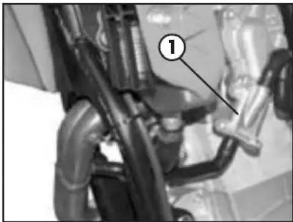
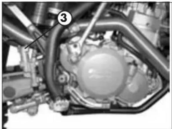
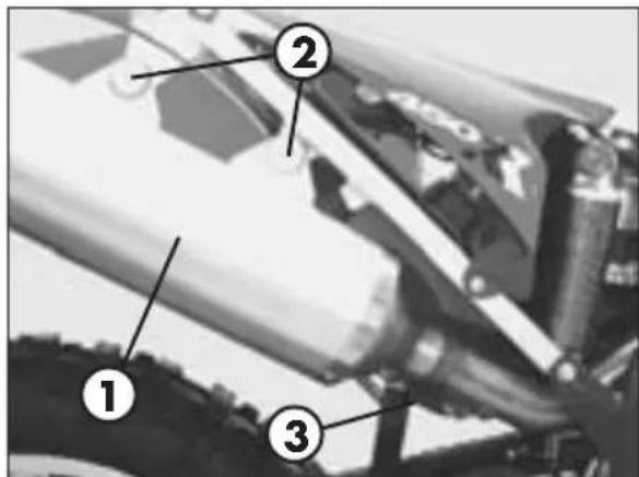
- Remove the silencer 1 unscrewing the two fixing screws 2 and the spring 3 united to the exhaust-pipe
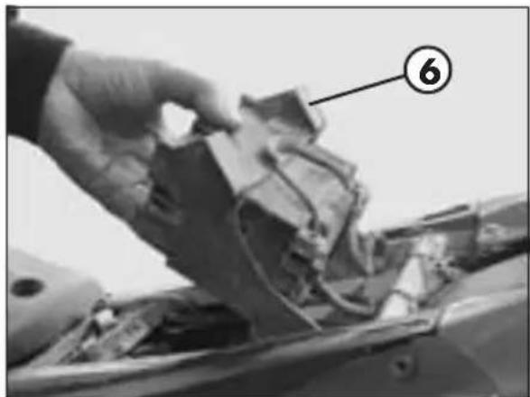
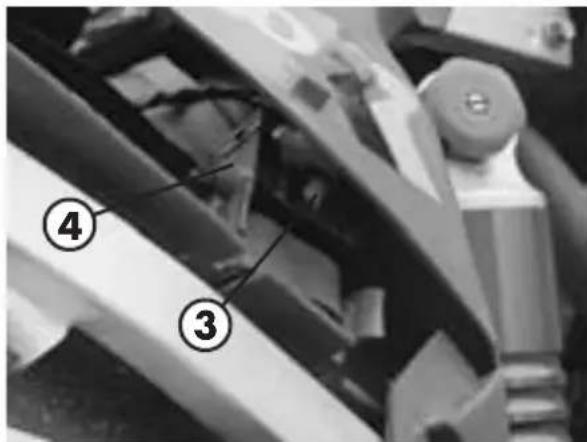
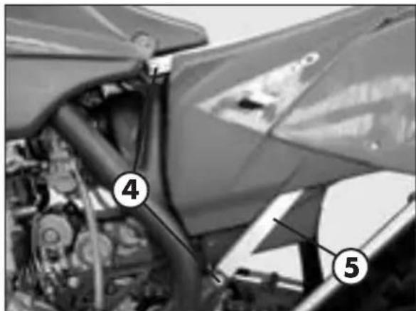
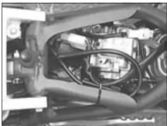
- Remove all the four fixing screws 4 (two on the right and two on the left) of the loom5
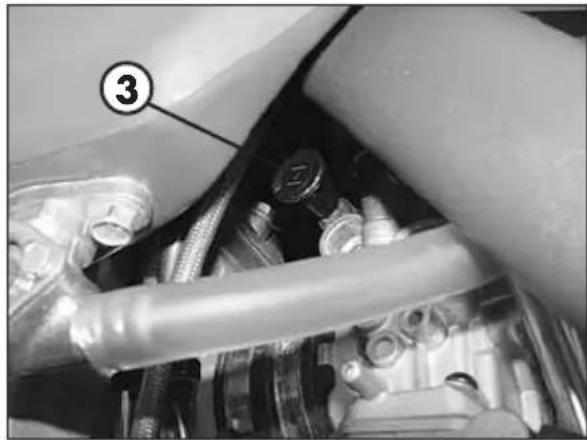
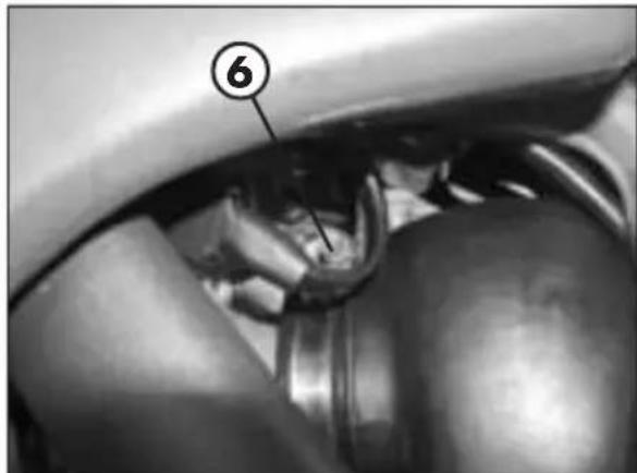
- Release with a screwdriver the coupling-box filter fixing clamp 6
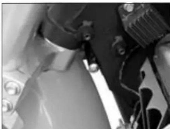
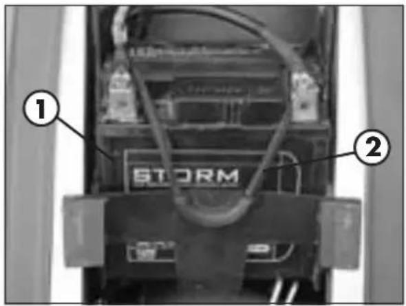
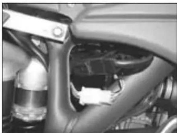
- Disconnect the back plant connectors and the starting relé cutting the clamp (the picture on the bottom shows the connectors disposition under the tank)
5
- Unthread the loom 5 toward the back
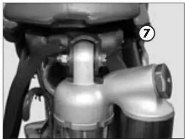
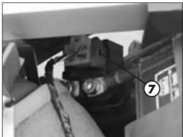
- Remove the upper fixing bolt of the damper 7 in order to make it possible for the exhaust-pipe to pass
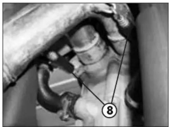
- Remove the two springs attacked to the cylinder 8.
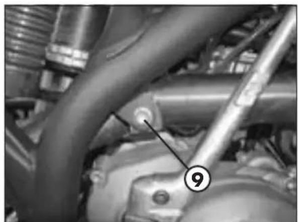
- Unscrew the bolt 9 over the lever set in motion and remove the tube running it from the back.
In order to reassemble it follow the inverted procedure
CONTENTS
CHARTER 6 TROUBLESHOOTING
INDEX
| PROBLEM CAUSE | REMEDY |
| Engine does not start | - Fuel system clogged (fuel lines, fuel tank, fuel cock). Clean the system. |
| - Air filter dirty. Proceed as described on page 119. | |
| - No current supplied to spark plug. Clean or replace the spark plug. If the problem persists, contact a BETAMOTOR dealer. | |
| - Engine flooded. Operate the startup pedal 5-10 times or the electrical starter pushbutton 2 times every 5 seconds. If the vehicle does not start, remove and dry the spark plug. | |
| Engine misfires | - Spark gap wrongly adjusted. Restore the spark gap. |
| - Spark plug dirty. Clean or replace the spark plug. | |
| Engine knocks | - Spark advance excessive. Check the ignition timing. |
| - Carbon formation in cylinder or on spark plug. Contact a BETAMOTOR dealer. | |
| Engine overheats and loses power | - Silencer partly clogged. Contact a BETAMOTOR dealer. |
| - Exhaust port clogged. Contact a BETAMOTOR dealer. | |
| - Ignition delayed. Check the timing. | |
| Front braking poor | - Brake pads worn. Follow the procedure described on page 144. |
| - Air or humidity in the hydraulic circuit. Follow the procedure described on page 114. | |
| Rear braking poor | - Brake pads worn. Follow the procedure described on page 145. |
| - Air or humidity in the hydraulic circuit. Follow the procedure described on page 115. |
Adjusting decompressor 138
Air filter 119
Bleeding clutch 117
Bleeding the brakes: front and rear 114
Brakes, adjustment: front and rear 138
Carburetor 121
Checks to be performed before each ride. 104
Clutch, adjustment 139
Clutch oil: check the level 117
Controls 88
Coolant 124
Engine oil: check 110
Engine oil: renewal 111
Fork oil: right/left rod. 118
Front and rear brake: check pads. 116
1 Front and rear brake: check the level 114
Handlebars, adjustment 139
Recommended lubricants 105
Refuelling 108
Replacing exhaust-pipe 147
Replacing the brake pads: front and rear 144
Replacing the bulbs 146
Running-in 105
Scheduled maintenance 134
Spark plug 120
94
Starting 106
Steering, check and adjustment 140
Steering lock 86
Suspensions: telescopic fork and shock absorber 130
Tensioning the chain 141
Throttle play, adjustment 140
Troubleshooting 150
Vehicle identification data 84
Wiring diagrams 98

RR 400 - 450 - 525
Pression bar (tou-terrain) avant 1,0 / arriere 1,0
6 COMMANDES A CABLE FLEXIBLE