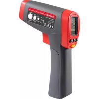
IR712 - Infrared thermometer Amprobe - Free user manual and instructions
Find the device manual for free IR712 Amprobe in PDF.


| Product type | Infrared thermometer |
| Brand | Amprobe |
| Model | IR712 |
| Temperature range | -18 °C to 550 °C (0 °F to 1022 °F) |
| Accuracy (at 21-25°C) | ±1.8% or ±1.8°C (±4°F), whichever is greater |
| Resolution | 0.1 °C / 0.1 °F |
| Distance to spot ratio (D:S) | 12:1 |
| Minimum spot size | 25 mm |
| Spectral response | 8 μm to 14 μm |
| Emissivity | Adjustable from 0.10 to 1.00 in 0.01 steps (preset 0.95) |
| Targeting laser | Class 2, <1 mW, 630-670 nm |
| Response time (95%) | 250 ms |
| Display | Dual LCD with backlight |
| Memory functions | MAX, MIN, DIF, AVG |
| Display hold | 8 seconds after trigger release |
| Auto power off | 8 seconds of inactivity |
| Power supply | 9V alkaline battery (type 6F22) |
| Battery life | Approximately 10 h (laser + backlight on) / 30 h (off) |
| Dimensions (H x W x D) | 169 x 138 x 53 mm |
| Weight | Approximately 290 g (with battery) |
| Operating temperature | 0 °C to 50 °C (32 °F to 120 °F) |
| Operating humidity | 0% to 75% non-condensing |
| Storage temperature | -20 °C to 65 °C (without battery) |
| Tripod mounting | Yes |
| Package contents | Thermometer, carrying case, installed 9V battery, instruction manual |
| Lens care | Dry compressed air, soft brush, cotton swab with alcohol (no solvent) |
| Housing care | Soft cloth with soapy water (do not immerse) |
| Warranty | 1 year (except batteries, fuses, misuse) |
Frequently Asked Questions - IR712 Amprobe
User questions about IR712 Amprobe
0 question about this device. Answer the ones you know or ask your own.
Ask a new question about this device
Download the instructions for your Infrared thermometer in PDF format for free! Find your manual IR712 - Amprobe and take your electronic device back in hand. On this page are published all the documents necessary for the use of your device. IR712 by Amprobe.
USER MANUAL IR712 Amprobe
Limited Warranty and Limitation of Liability
Your Amprobe product will be free from defects in material and workmanship for one year from the date of purchase, unless local laws require otherwise. This warranty does not cover fuses, disposable batteries or damage from accident, neglect, misuse, alteration, contamination, or abnormal conditions of operation or handling. Resellers are not authorized to extend any other warranty on the behalf of Amprobe. To obtain service during the warranty period, return the product with proof of purchase to an authorized Amprobe Service Center or to an Amprobe dealer or distributor. See Repair Section for details. THIS WARRANTY IS YOUR ONLY REMEDY. ALL OTHER WARRANTYES - WHETHER EXPRESS, IMPLIED OR STATUTORY - INCLUDING IMPLIED WARRANTY OF FITNESS FOR A PARTICULAR PURPOSE OR MERCHANTABILITY, ARE HEREBY DISCLAIMED. MANUFACTURER SHALL NOT BE LIABLE FOR ANY SPECIAL, INDIRECT, INCIDENTAL OR CONSEQUENTIAL DAMAGES OR LOSSES, ARISING FROM ANY CAUSE OR THEORY. Since some states or countries do not allow the exclusion or limitation of an implied warranty or of incidental or consequential damages, this limitation of liability may not apply to you.
Repair
All test tools returned for warranty or non-warranty repair or for calibration should be accompanied by the following: your name, company's name, address, telephone number, and proof of purchase. Additionally, please include a brief description of the problem or the service requested. Non-warranty repair or replacement charges should be remitted in the form of a check, a money order, credit card with expiration date, or a purchase order made payable to Amprobe.
In-Warranty Repairs and Replacement - All Countries
Please read the warranty statement and check your battery before requesting repair. During the warranty period any defective test tool can be returned to your Amprobe distributor for an exchange for the same or like product. Please check the "Where to Buy" section on www.Amprobe.com for a list of distributors near you. Additionally, in the United States and Canada, in-warranty repair and replacement units can also be sent to a Amprobe Service Center.
Non-Warranty Repairs and Replacement - US and Canada
Non-warranty repairs in the United States and Canada should be sent to an Amprobe Service Center. Call Amprobe or inquire at your point of purchase for current repair and replacement rates.
In USA In Canada
Amprobe Amprobe
Everett, WA 98203 Mississauga, ON L4Z 1X9
Tel: 877-AMPROBE (267-7623) Tel: 905-890-7600
Non-Warranty Repairs and Replacement - Europe
European non-warranty units can be replaced by your Amprobe distributor for a nominal charge. Please check the "Where to Buy" section on www.Amprobe.com for a list of distributors near you.
European Correspondence Address*
Amprobe® Europe
In den Engematten 14
79286 Glottertal, Germany
Tel.: +49 (0) 7684 8009 - 0
*Correspondence only - no repair or replacement available from this address. European customers please contact your distributor.)
CONTENTS
SYMBOL 2
SAFETY INFORMATION 3
UNPACKING AND INSPECTION 3
FEATURES 4
HOW THE THERMOMETERS WORK 4
OPERATING THE THERMOMETER 4
Temperature Measurement 4
Locating a Hot or Cold Spot 7
Distance and Spot Size 7
Field of View. 8
Emissivity 8
Reminders 8
TYPICAL MEASUREMENTS 9
SPECIFICATION 12
MAINTENANCE 12
TROUBLE SHOOTING 13
BATTERY REPLACEMENT 13
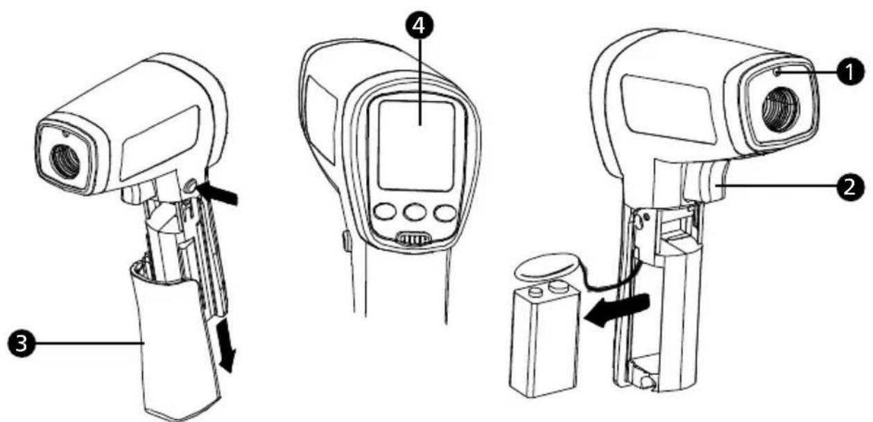
Laser Aperture
Trigger
3 Battery Cover
4 Display
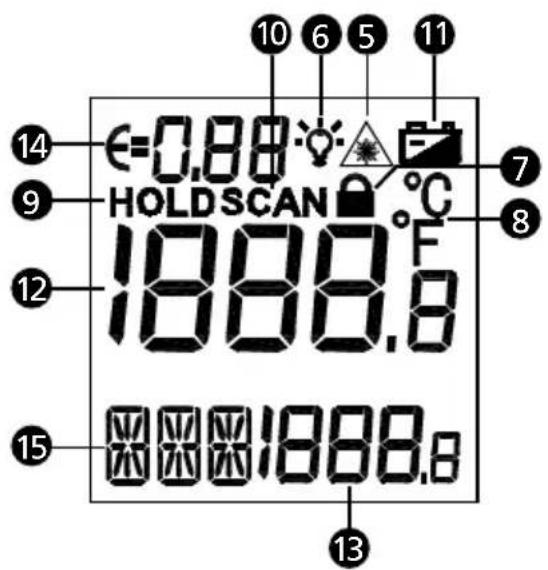
Laser "ON" symbol
Display backlight
Measurement lock (Continuous measurement)
8 Temperature unit (Celsius / Fahrenheit)
9 8 seconds auto display hold
10 Making measurement (Pulling the trigger)
11 Battery indicator
Primary display
Secondary display
14 Emissivity (Adjustable from 0.10 to 1.00)
15 MAX, MIN, DIF, AVG temperature values
SYMBOLS
| A | Caution! Refer to the explanation in this manual. |
| A | Warning! Laser light. Do not stare into laser beam. |
| °C | Celsius. |
| °F | Fahrenheit. |
| Battery indication. | |
| CE | Complies with European directives. |
| Do not dispose of this product as unsorted municipal waste.Contact a qualified recycler. |
The instrument complies with:
EN 61010-1 General Safety
EN 60825-1 Laser Safety
EN 61326-1 Electromagnetic Emissions and Susceptibility
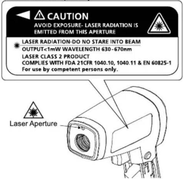
Warning
- Do not stare into laser beam.
- Do not point laser directly at eye or indirectly off reflective surfaces.
For use by competent persons only. - Replace the batteries as soon as the low-battery indicator appears.
- Do not use the thermometer if it operates abnormally.
- Do not operate the thermometer around explosive gas, vapor, or dust.
- To avoid a burn hazard or fire, know that reflective objects may be much hotter than the indicated temperature reading.
- Do not leave the thermometer on or near objects of high temperature.
- If the thermometer is used in a manner not specified by this manual, the protection provided by the thermometer may be impaired or may result in hazardous laser radiation exposure.
Cautions
To avoid damaging the thermometer under measurement, protect them from the following:
EMF (electro-magnetic fields) from arc welders, induction heaters
Static electricity
- Thermal shock (caused by large or abrupt ambient temperature changes — allow 30 minutes for instrument to stabilize before use)
- Do not leave the thermometer on or near objects of high temperature
UNPACKING AND INSPECTION
Your shipping carton should include:
1 Thermometer (IR-712 / IR-712-EUR or IR-720 / IR-720-EUR or IR-730 / IR-730-EUR)
1 Carrying case
1 9V battery (installed)
1 Users manual
If any of the items are damaged or missing, return the complete package to the place of purchase for an exchange.
The Amprobe IR-712 / IR-712-EUR, a 12:1 distance to spot ratio infrared thermometer, offers best in class accuracy and response time with a temperature measurement range of 0^ to 1022^ or -18^ to 550^ . The IR-712 / IR-712-EUR is specifically designed for HVAC/R, electrical, industrial maintenance, automotive as well as quality control and fire prevention applications.
12:1 Distance to Spot ratio
- Temperature range of 0^ to 1022^ or -18^ to 550^
- Precision accuracy and rapid response time
- Laser pointer, backlit dual LCD Display
- Auto display hold and MAX/MIN memory
- Adjustable emissivity for measuring a variety of materials
The Amprobe IR-720 / IR-720-EUR, a 20:1 distance to spot ratio infrared thermometer, offers best in class accuracy and response time with a temperature measurement range of -26^ to 1922^ or -32^ to 1050^ . The IR-720 / IR-720-EUR is specifically designed for HVAC/R, electrical, industrial maintenance, automotive as well as quality control and fire prevention applications.
20:1 Distance to Spot ratio
- Temperature range of -26^ to 1922^ or -32^ to 1050^
- Precision accuracy and rapid response time
- Laser pointer, backlit dual LCD Display
- Auto display hold and MAX/MIN memory
- Adjustable emissivity for measuring a variety of materials
The Amprobe IR-730 / IR-730-EUR, a 30:1 spot to distance ratio infrared thermometer, offers best in class accuracy and response time with a temperature measurement range of -26^ to 2282^ or -32^ to 1250^ . The IR-730 / IR-730-EUR is specifically designed for HVAC/R, electrical, industrial maintenance, automotive as well as quality control and fire prevention applications.
30:1 Distance to Spot ratio
- Temperature range of -26^ to 2282^ or -32^ to 1250^
- Precision accuracy and rapid response time
- Laser pointer, backlit dual LCD Display
- Auto display hold and MAX/MIN memory
- Adjustable emissivity for measuring a variety of materials
HOW THE THERMOMETERS WORK
Infrared thermometers measure the surface temperature of an object. The thermometer's optics sense emitted, reflected, and transmitted energy, which is collected and focused onto a detector. The unit's electronics translate the signal into a temperature reading which the unit displays.
OPERATING THE THERMOMETER
Temperature Measurement
The thermometer will turn on when you pull the trigger and also features an auto-off function that automatically powers down the thermometer after 8 seconds of inactivity.
To measure temperature, point the thermometer at an object and pull the trigger. You can use the laser pointer to help aim the thermometer. Pull and hold the trigger when measuring the target surface. When the trigger is released, the display will hold the reading for 8 seconds. Be sure to consider distance-to-spot size ratio and field of view. The laser is used for aiming only and is not related to temperature measurement.
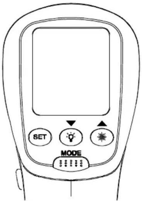
Rotary Switch Positions
| Button Description | |
| MODE | Press MODE button to toggle between MAX, MIN, DIF, and AVG options. When the thermometer goes into sleep mode, press MODE to turn the thermometer ON again and it displays the last measurement result. |
| SET | Press to enter set-up mode stepping through Emissivity, Trigger Lock and Switching °C/°F set-up. Details refer to the below Emissivity, Trigger Lock and °C / °F set-up. |
| /▼ | Press to turn the display backlight ON or OFF. When the thermometer enters the setup up mode, press to select a set-up option (Emissivity, Trigger lock, Switching °C / °F). |
| /▲ | Press to turn the laser light ON or OFF. When the thermometer enters the setup up mode, press to select a set-up option (Emissivity, Trigger lock, Switching °C / °F). |
Emissivity set-up
- Press SET button to select Emissivity set-up, icon is blinking on the display
- Press to increase the value by 0.01. Press and hold or quick setting. The maximum value is 1.00.
- Press to decrease the value by 0.01. Press and hold or quick setting. The minimum value is 0.01.
- Press MODE button to complete the setting and exit Emissivity set-up, or press SET button to complete the setting and continue setting for Trigger Lock.
Note: Default emissivity is 0.95.
Table of Surface Emissivity
| Measure Surface Switch Setting | |
| METALS | |
| Aluminum | |
| Oxidized 0.2 – 0.4 | |
| Alloy A3003 | |
| Oxidized 0.3 | |
| Roughened 0.1 – 0.3 | |
| Brass | |
| Burnished 0.3 | |
| Oxidized 0.5 | |
| Cooper | |
| Oxidized 0.4 – 0.8 | |
| Electrical Terminal Blocks 0.6 | |
| Haynes | |
| Alloy 0.3 – 0.8 | |
| Inconel | |
| Oxidized 0.7 – 0.95 | |
| Sandblasted 0.3 – 0.6 | |
| Electoropolished 0.15 | |
| Iron | |
| Oxidized 0.5 – 0.9 | |
| Rusted 0.5 – 0.7 | |
| Iron Cast | |
| Oxidized 0.6 – 0.95 | |
| Unoxidized 0.2 | |
| Molten 0.2 – 0.3 | |
| Iron Wrought | |
| Dull 0.9 | |
| Lead | |
| Rough 0.4 | |
| Oxidized 0.2 – 0.6 | |
| Molydbenum | |
| Oxidized 0.2 – 0.6 | |
| Nickel | |
| Oxidized 0.2 – 0.5 | |
| Platinum | |
| Black | 0.9 |
| Steel | |
| Cold-Rolled 0.7 – 0.9 | |
| Ground Sheet | 0.4 – 0.6 |
| Polished Sheet | 0.1 |
| Zinc | |
| Oxidized 0.1 | |
| Measure Surface | Switch Setting |
| NON-METALS | |
| Asbestos | 0.95 |
| Asphalt 0.95 | |
| Basalt 0.7 | |
| Carbon | |
| Unoxidized | 0.8 – 0.9 |
| Graphite | 0.7 – 0.8 |
| Carborundum | 0.9 |
| Ceramic | 0.95 |
| Clay | 0.95 |
| Concrete | 0.95 |
| Cloth | 0.95 |
| Glass | |
| Plate | 0.85 |
| Gravel | 0.95 |
| Gypsum | 0.8 – 0.95 |
| Ice | 0.98 |
| Limestone | 0.98 |
| Paper (any colour) | 0.95 |
| Plastic | |
| Opaque | 0.95 |
| Soil | 0.9 – 0.98 |
| Water | 0.93 |
| Wood, (natural) | 0.9 – 0.95 |
Trigger Lock
The thermometer trigger can be locked on for continuous measurement. To lock the trigger:
- Press SET button to select Trigger Lock set-up, icon is blinking on the display
- Press or to select ON or OFF.
- Press MODE button to complete the setting and exit Trigger Lock set-up, or press SET button to complete the setting and continue setting for ^ C / ^ F
^ C / ^ Set-up
- Press SET button to select ^ C / F set-up, icon ^ C or ^ F is blinking on the display
- Press or to select ^ C or ^ F .
- Press MODE button to complete the setting and exit ^ C / ^ F set-up.
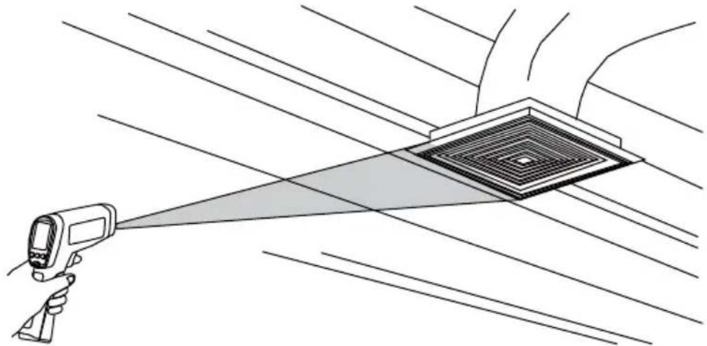
Locating a Hot or Cold Spot
To find a hot or cold spot, aim the thermometer outside the target area. Then, slowly scan across the area with an up and down motion until you located the hot or cold spot.
Distance and Spot Size
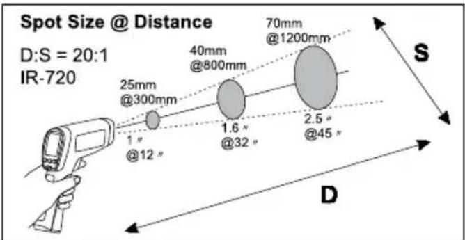
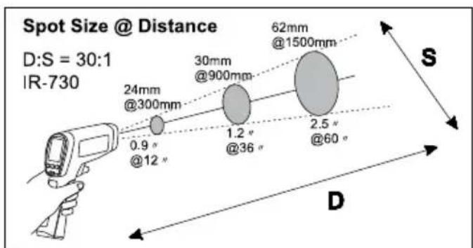
As the distance (D) from the target being measured increases, the spot size (S) of the area measured by the instrument becomes larger. The spot size indicates 90% encircled energy.

Field of View
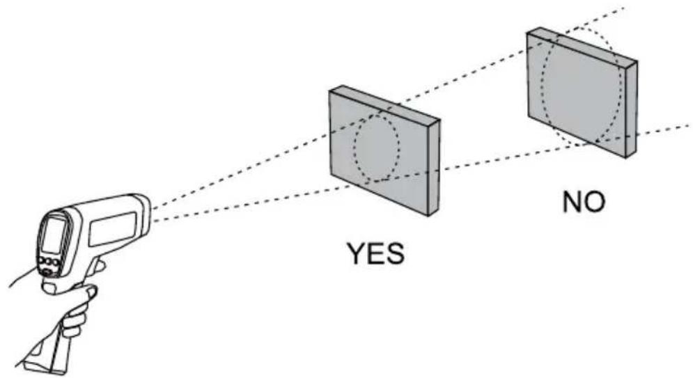
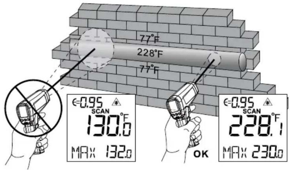
Make sure that the target is larger than the spot size. The smaller the target, the closer you should be to it.
Emissivity
Emissivity describes the energy-emitting characteristics of materials. Most organic materials and painted or oxidized surfaces have an emissivity of about 0.95.
If possible, to compensate for inaccurate readings that may result from measuring shiny metal surfaces, cover the surface to be measured with masking tape or flat black paint (<150^ / 302^) and use the high emissivity setting. Allow time for the tape or paint to reach the same temperatures as the surface beneath it. Measure the temperature of the tape or painted surface.
If you cannot use paint or use tape, then you could improve the accuracy of your measurements with the emissivity selector. Even with emissivity selector, it can be difficult to get a completely accurate infrared measurement of a target with a shiny or metallic surface.
The thermometer allows you to adjust the emissivity setting for the type of surface before taking measurements. To determine the adjustment setting please refer to Table of Surface Emissivity.
Reminders
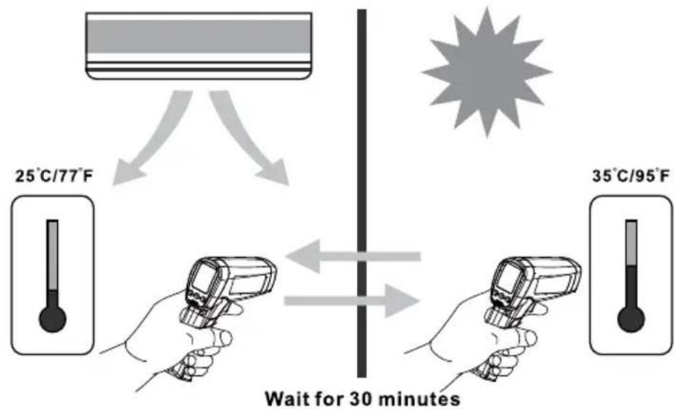
- Changes of surrounding ambient temperature can result in inaccurate readings, allow time for the instrument to adopt the change of ambient temperatures before use. Specified accuracy applies after 30 minutes when the instrument changes to a different environment ambient temperatures.
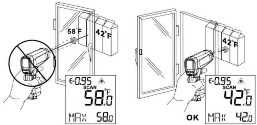
- The instrument cannot measure through transparent surfaces such as glass. It will measure the surface temperature of the glass instead.
- See Table of Surface Emissivity for use in measuring shiny or polished metal surfaces (stainless steel, aluminum, etc.).
- Steam, dust, smoke, etc., can prevent accurate measurements by obstructing the instrument's optics.
TYPICAL MEASUREMENTS
This section describes a variety of measurements often performed by technicians.
Reminder:
- User may select to turn on or off the backlight and laser whenever you are making readings with the thermometer.
- Relatively high emissivity normally means emissivity setting of about 0.95.
- Relatively low emissivity normally means emissivity setting of about 0.30.
- When user cannot identify the emissivity of the object to be measured, user could cover the surface to be measured (temperature >150^ ) with black electric tape (emissivity of about 0.95). Allow time for the tape to reach the same temperature as the object to be measured. Measure and record the temperature of the tape.
Aim the thermometer at the object to be measured, adjust the emissivity setting to make it as the same temperature as the tape. At this time, the thermometer emissivity setting is close to the emissivity of the object to be measured, measurement may be taken.
Testing Contactors (Starters)
- Press SET to select emissivity. Press / to select relatively low emissivity for bright contacts, or 0.7 mid level for darkened contacts.
- Press MODE to select MAX.
- Measure line and load side of one pole without releasing trigger.
- A temperature difference between the line and load sides of a pole indicate increased resistance of one point and a contactor may be failing.
Testing Enclosed Relays
- Press SET and then press / to set emissivity to relatively low for un-insulated connectors or relatively high for plastic encased relays or for Bakelite enclosed relays or insulated connectors.
- Press MODE to select MAX.
- Start to scan.
- Measure the relay casing, looking for hot spots.
- Measure electrical connections on relay terminals looking for hot spots.
Testing Fuses and Buss Connections
- Press SET and then press / to set emissivity to relatively high for paper covered fuse body or insulated connections.
- Press MODE to select MAX.
- Scan the paper covered length of fuse.
- Without releasing the trigger, scan each fuse. Unequal temperatures between fuses may indicate voltage or amperage imbalance.
- Press SET and then press / to set emissivity to relatively low, for metal fuses and caps and insulated buss connections.
- Press MODE to select MAX.
- Scan each end cap on each fuse.
Note: Unequal temperatures or a high temperature indicates loose or corroded connection through the fuse buss spring clip
Scanning Walls for Air Leaks or Insulation Deficiencies
- Turn off heating, cooling, and blower.
- Press SET to select emissivity. Press / to select emissivity relatively high for painted surfaces or window surfaces.
- Press MODE to select MIN when opposite the side of the wall is at a lower temperature and/or select MAX when the opposite side of the wall is at a higher temperature.
- Measure an interior partition wall surface temperature.
- Do not release the trigger. Record this temperature as your baseline (or benchmark) for a "perfectly" insulated wall.
- Face the wall to be scanned. Stand 1.5m away to scan a 6cm spot on the wall (D:S=30:1). Also refer to "Field of View" section for D:S=12:1 and D:S=20:1 Distance to Spot ratio.
- Scan horizontal rows of wall from top to bottom, or horizontal rows of ceiling from wall to wall. Look for greatest deviations from baseline temperature to identify problems. This completes the insulation test scan.
Turn on the blower (no heat, no cooling) and retest. If test results with the blower on are different than results with the blower off, this may indicate air leaks in conditioned envelope walls. The air leaks are caused by duct leaks that create a pressure differential across the conditioned space envelope.
Testing Bearings
Warning - To avoid injury when testing bearings:
- Do not wear loose clothing, jewelry, or anything around neck when working around moving parts such as motors, belts, blower, and fans.
- Make sure an electrical disconnect is within reach and operating correctly and freely.
- Do not work alone.
Note: It works best to compare two similar motors operating similar loads
- Press SET and then press / to select relatively high emissivity.
- Press MODE to select MAX.
- Enable motor and allow it to reach steady state operating temperatures.
- Disable the motor if possible.
- Measure the two motor bearing temperatures.
- Compare the two motor bearing temperatures. Unequal temperatures or a high temperature can indicate a lubrication or other bearing problem that is resulting from excess friction.
- Repeat the sequence for the blower bearings.
Testing Belts and Sheaves
- Press SET and then press / to select relatively high emissivity.
- Press MODE to select MAX.
- Enable the motor and allow it to reach a steady state operating temperatures.
- Aim the thermometer at the surface to be measured.
- Start recording temperature.
- Slowly move the thermometer up the belt toward second sheave.
If belt is slipping, sheave temperature will be high from friction.
- If belt is slipping, belt temperature will remain high between sheaves.
- If belt is not slipping, belt temperature will reduce between sheaves.
- If inner surfaces of sheaves are not a true "V" shape, this indicates belt slippage and will continue to operate at elevated temperatures until sheave is replaced.
- Sheaves must be properly aligned (include "pitch & yaw") for belt and sheaves to operate at appropriate temperatures. A straight edge or taut string, can be used to check alignments.
- Motor sheave should operate at a temperature consistent with blower sheaves.
- If motor sheave is at a higher temperature at motor shaft than at outer circumference, belt is probably not slipping.
- If outer circumference of sheave is at a higher temperature than sheave at motor shaft, then the belt is probably slipping and sheaves may be misaligned.
Checking for Blockage in Air-To-Air Evaporator or Condensers
- Remove panels to gain access to coil return bends or hairpins.
- Press SET and then press / to select relatively high emissivity for copper tube.
- Start the refrigeration system.
- Aim the thermometer at coil turn bends/hairpins.
- Start recording temperature.
-
Take temperature of each return bend/hairpin.
-
All evaporator return bends/hairpins should be at or slightly above evaporator saturation temperature from the pressure/temperature chart.
- All condenser return bend/hairpins should be at or slightly less than condenser saturation temperature.
- If a group of return bends/hairpins do not conform to expected temperatures, that indicates a blocked or restricted distributor or distributor tube.
DETAILED SPECIFICATIONS
| Feature IR-712 / IR-712-EUR IR-720 / IR-720 | EUR IR-730 / IR-730-EUR | ||
| Temperature Range | -18°C to 550°C (0°F to 1022°F) | -32°C to 1050°C (-26°F to 1922°F) | -32°C to 1250°C (-26°F to 2282°F) |
| Accuracy (Assumes ambient operating temperature of 21°C to 25°C (70°F to 77°F) | ±1.8% or ±1.8°C (±4F), whichever is greater (Typical) | >0°C to 1250°C (>32°F to 2282°F): ±1.8% or ±1.8°C (±4F), whichever is greater (Typical) -32°C to 0°C (-26°F to 32°F): ±1.8%+1°C (2°F) or ±2.8°C (±6F), whichever is greater (Typical) | |
| Repeatability ±0.5% of reading or ±0.5°C (±1°F), whichever is greater (Typical) | |||
| Display Resolution 0.1°C / 0.1°F | |||
| Spectral Response 8μm to14μm | |||
| Laser Sighting Single point laser | |||
| Laser Power Output >1 mW Class 2, wavelength 630 to 670nm | |||
| Response Time (95%) 250ms | |||
| Distance to Spot (D:S) 12:1 | 20:1 30:1 | ||
| Minimum Spot Size 25mm | 25mm 24mm | ||
| Emissivity | digitally adjustable from 0.10 to 1.00 by 0.01. Pre-set emissivity is 0.95 | ||
| Ambient Operating Temperature | 0°C to 50°C / 32°F to 120°F | ||
| Relative Humidity | 0% to 75% non-condensing | ||
| Storage Temperature | -20°C to 65°C / -4°F to 150°F (Battery not installed) | ||
| Temperature Display °C or °F selectable | |||
| Display Hold | 8 seconds | ||
| MAX/MIN Temperature Display | ✓ | ✓ | ✓ |
| DIF/AVG Temperature Display | ✓ | ✓ | ✓ |
| Dual LCD Display | ✓ | ✓ | ✓ |
| LCD Backlit | ✓ | ✓ | ✓ |
| Low Battery Indication | ✓ | ✓ | ✓ |
| Tripod mount | ✓ | ✓ | ✓ |
| Power | 9V 6F22 alkaline battery or equivalent | ||
| Battery Life | 10 hours with laser and backlight on30 hours with laser and backlight off | ||
| Dimension (H x L x W) | Approximately 169 x 138 x 53 mm (6.7 x 5.4 x 2.1 in) | ||
| Weight | Approximately 290 g (0.64 lb) with battery installed | ||
MAINTENANCE
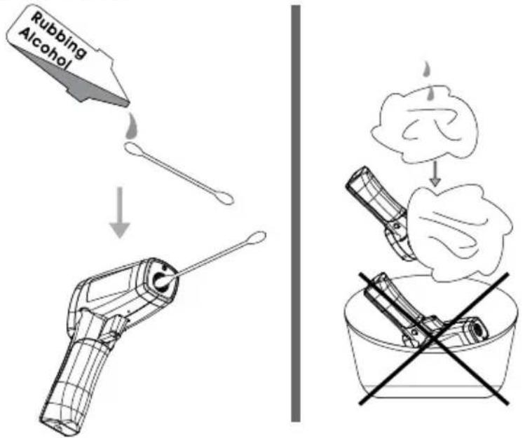
Lens Cleaning: Blow off loose particles using clean compressed air. Gently brush remaining debris away with a camel hair brush. Carefully wipe the surface with a moist cotton swab. The swab may be moistened with water or rubbing alcohol.
NOTE: DO NOT use solvents to clean the plastic lens.
Case Cleaning: Use soap and water on a damp sponge or soft cloth.
Do not submerge the unit in water.
TROUBLE SHOOTING
| Code Problem Action | ||
| OL Target temperature is over range Select target within specifications | ||
| -OL Target temperature is under range Select target within specifications | ||
| Battery indication | Low battery Check and/or replace battery | |
| Blank display Possible dead battery Check and/or replace battery | ||
| Laser does not work | 1. Low or dead battery2. Ambient temperature above 40°C (104°F) | 1. Replace battery2. Use in area with lower ambient temperature |
BATTERY REPLACEMENT
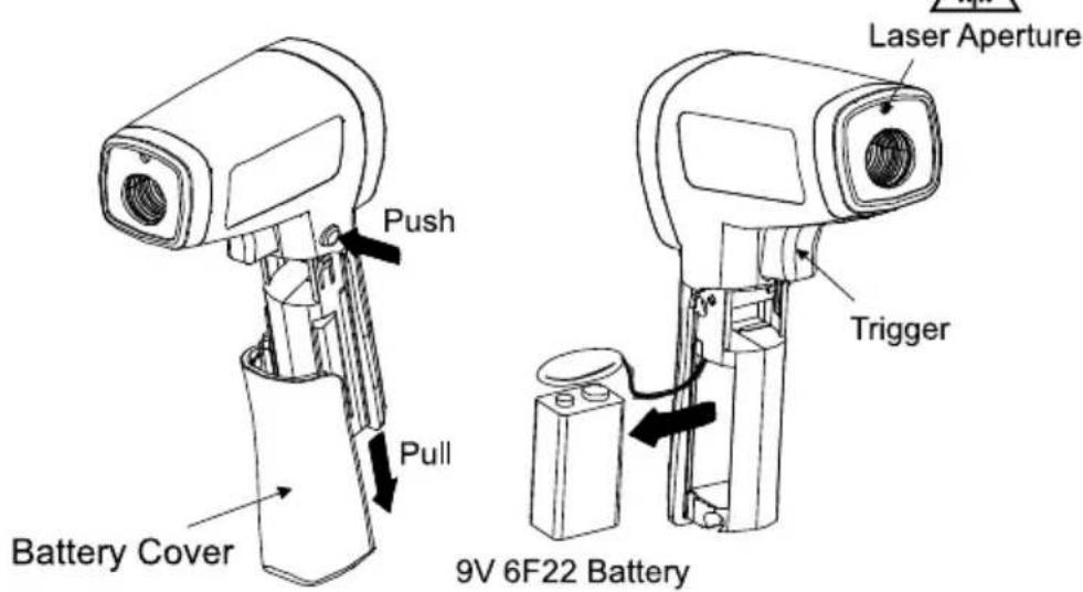
To install or change one 9V battery (see below):
- Push the button and pull the handle downward to open battery cover.
- Install the battery noting its correct polarity.
- Re-install the battery cover.
Battery: 9V 6F22 alkaline battery or equivalent
IR-712
IR-712-EUR
Thermomètre IR 12:1
IR-720
IR-720-EUR
Thermomètre IR 20:1
IR-730
IR-730-EUR
Thermomètre IR 30:1
Mode d'emploi
CÓM OFU NCFIONA EL TERMOMETRO
ANVANDA TERMOMETERN 4
Temperaturmätning 4
Visit www.Amprobe.com for
Catalog
Application notes
Product specifications
- User manuals
Amprobe
www.Amprobe.com
info@amprobe.com
Everett, WA 98203
Tel: 877-AMPROBE (267-7623)
Amprobe® Europe
Beha-Amprobe
In den Engematten 14
79286 Glottertal, Germany
Tel.: +49 (0) 7684 8009 - 0

Please
Recycle
- Limited Warranty and Limitation of Liability
- Repair
- In-Warranty Repairs and Replacement - All Countries
- Non-Warranty Repairs and Replacement - US and Canada
- Non-Warranty Repairs and Replacement - Europe
- CONTENTS
- Warning
- Cautions
- UNPACKING AND INSPECTION
- HOW THE THERMOMETERS WORK
- OPERATING THE THERMOMETER
- Temperature Measurement
- Rotary Switch Positions
- Emissivity set-up
- Trigger Lock
- ° C / °F Set-up
- Locating a Hot or Cold Spot
- Distance and Spot Size
- Field of View
- Emissivity
- Reminders
- TYPICAL MEASUREMENTS
- Reminder:
- Testing Contactors (Starters)
- Testing Enclosed Relays
- Testing Fuses and Buss Connections
- Scanning Walls for Air Leaks or Insulation Deficiencies
- Testing Bearings
- Testing Belts and Sheaves
- Checking for Blockage in Air-To-Air Evaporator or Condensers
- MAINTENANCE
- BATTERY REPLACEMENT
- CÓM OFU NCFIONA EL TERMOMETRO
- Visit www.Amprobe.com for
- Amprobe
- Amprobe® Europe
Brand : Amprobe
Model : IR712
Category : Infrared thermometer