(LA) — Lawn mower — Mode d'emploi PDF")
CG31EBS(P)(LA) - Lawn mower HITACHI - Free user manual and instructions
Find the device manual for free CG31EBS(P)(LA) HITACHI in PDF.
| Technical Specifications | 2-stroke engine, 31 cc displacement, 0.9 kW power |
|---|---|
| Cutting Width | 40 cm |
| Cutting Height | Adjustable from 25 to 75 mm |
| Starting Type | Manual start |
| Tank Capacity | 0.65 L |
| Weight | Approximately 15 kg |
| Usage | Ideal for medium-sized gardens, easy to maneuver |
| Maintenance | Regularly check oil, clean air filter, sharpen blades |
| Safety | Wear safety glasses and gloves, do not use in rain |
| General Information | 2-year warranty, spare parts available |
Frequently Asked Questions - CG31EBS(P)(LA) HITACHI
User questions about CG31EBS(P)(LA) HITACHI
0 question about this device. Answer the ones you know or ask your own.
Ask a new question about this device
Download the instructions for your Lawn mower in PDF format for free! Find your manual CG31EBS(P)(LA) - HITACHI and take your electronic device back in hand. On this page are published all the documents necessary for the use of your device. CG31EBS(P)(LA) by HITACHI.
USER MANUAL CG31EBS(P)(LA) HITACHI
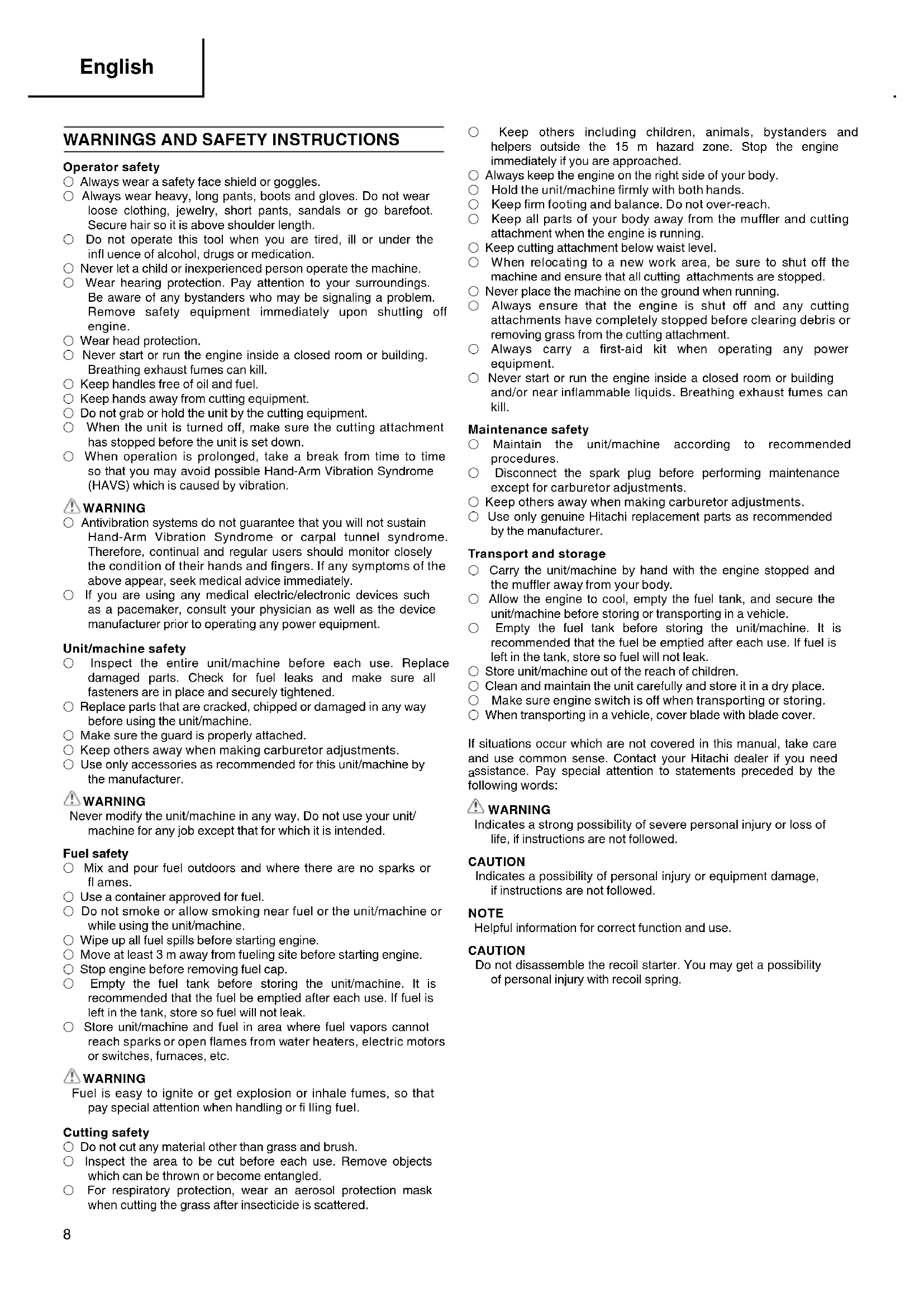
Brush Cutter Motorsense Debroussailleuse Decespugliatore Motor bosmaier Desbrozadoras Roçadora
CG 31EBS (P)/CG 31EBS (LP)


Read the manual carefully before operating this machine.
Lesen Sie vor der Verwendung diese Anleitung sorgfältig durch.
Lire attentivement le manuel avant d'utiliser la machine.
Leggere attentamente il manuale prima di mettere in funzione esta apparecchiatura.
Lees de handleiding zorgvuldig door voordat u de machine bedient.
Antes de utiliser estaquina, lea cautadosamente el manual.
Leia o manual atentamente antes de operar estaquina.
Handling instructions Bedienungsanleitung Mode d'emploi Istruzioni per l'uso Gebruiksaanwijzing Instrucciones de manejo Instruções de uso


1215

13 14 16


17 18 19


MEANINGS OF SYMBOLS
NOTE: Some units do not carry them.
| Symbols WARNING The following show symbols used for the machine. Be sure that you understand their meaning before use. | |||
| It is important that you read, fully understand and observe the following safety precautions and warnings. Careless or improper use of the unit may cause serious or fatal injury. | Max 9,900rpm | Shows maximum shaft speed. Do not use the cutting attachment whose max rpm is below the shaft rpm. | |
| Read, understand and follow all warnings and instructions in this manual and on the unit. | Gloves should be worn when necessary, e.g., when assembling cutting equipment. | ||
| Always wear eye, head and ear protectors when using this unit. | Use anti-slip and sturdy footwear. | ||
| Be careful of the engine. Engine gets hot by running engine. | Blade thrust may occur when the spinning blade contacts a solid object in the critical area. A dangerous reaction may occur causing the entire unit and operator to be thrust violently. This reaction is called blade thrust. As a result, the operator may lose control of the unit which may cause serious or fatal injury. Blade thrust is more likely to occur in areas where it is difficult to see the material to be cut. | ||
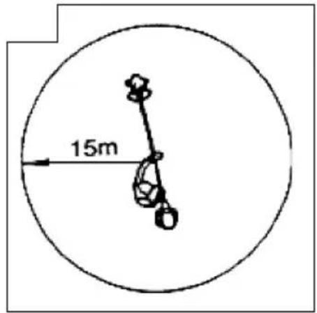
| Keep all children, bystanders and helpers 15 m away from the unit. If anyone approaches you, stop the engine and cutting attachment immediately. | |||
| Be careful of thrown objects. | Do not attach handle above this point | Indicate handle location. Do not attach handle above this point. | |
Contents
WHATIS WHAT
WARNING AND SAFETY INSTRUCTIONS 8
SPECIFICATIONS 9
ASSEMBLY PROCEDURES 10
OPERATING PROCEDURES 10
MAINTENANCE 12
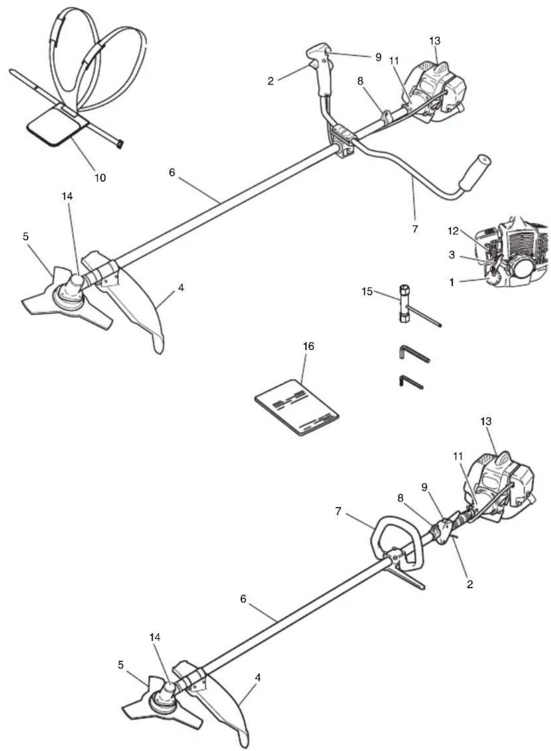
WHAT IS WHAT
Since this manual covers several models, there may be some difference between pictures and your unit. Use the instructions that apply to your unit.
- Fuel cap
- Throttle lever
- Starter handle
- Blade guard
- Cutting attachment
- Drive shaft tube
- Handle
- Suspension eyelet
- Ignition switch
- Harness
- Clutch case
- Choke lever
- Engine
- Angle transmission
- Combi box spanner
- Handling instructions
WARNING AND SAFETY INSTRUCTIONS
Operator safety
Always wear a safety face shield or goggles.
Always wear heavy, long pants, boots and gloves. Do not wear loose clothing, jewelry, short pants, sandals or go barefoot. Secure hair so it is above shoulder length.
Do not operate this tool when you are tired, ill or under the influence of alcohol, drugs or medication.
Never let a child or inexperienced person operate the machine.
- Wear hearing protection. Pay attention to your surroundings.
- Be aware of any bystanders who may be signaling a problem.
- Remove safety equipment immediately upon shutting off engine.
Wear head protection.
- Never start or run the engine inside a closed room or building. Breathing exhaust fumes can kill.
Keep handles free of oil and fuel.
Keep hands away from cutting equipment.
Do not grab or hold the unit by the cutting equipment.
- When the unit is turned off, make sure the cutting attachment has stopped before the unit is set down.
When operation is prolonged, take a break from time to time so that you may avoid possible Hand-Arm Vibration Syndrome (HAVS) which is caused by vibration.
WARNING
Antivibration systems do not guarantee that you will not sustain Hand-Arm Vibration Syndrome or carpal tunnel syndrome. Therefore, continual and regular users should monitor closely the condition of their hands and fingers. If any symptoms of the above appear, seek medical advice immediately.
If you are using any medical electric/electronic devices such as a pacemaker, consult your physician as well as the device manufacturer prior to operating any power equipment.
Unit/machine safety
Inspect the entire unit/machine before each use. Replace damaged parts. Check for fuel leaks and make sure all fasteners are in place and securely tightened.
Replace parts that are cracked, chipped or damaged in any way before using the unit/machine.
Make sure the guard is properly attached.
Keep others away when making carburetor adjustments.
Use only accessories as recommended for this unit/machine by the manufacturer.
WARNING
Never modify the unit/machine in any way. Do not use your unit/ machine for any job except that for which it is intended.
Fuel safety
Mix and pour fuel outdoors and where there are no sparks or flames.
Use a container approved for fuel.
- Do not smoke or allow smoking near fuel or the unit/machine or while using the unit/machine.
Wipe up all fuel spills before starting engine.
Move at least 3 m away from fueling site before starting engine.
Stop engine before removing fuel cap.
Empty the fuel tank before storing the unit/machine. It is recommended that the fuel be emptied after each use. If fuel is left in the tank, store so fuel will not leak.
- Store unit/machine and fuel in area where fuel vapors cannot reach sparks or open flames from water heaters, electric motors or switches, furnaces, etc.
WARNING
Fuel is easy to ignite or get explosion or inhale fumes, so that pay special attention when handling or fliling fuel.
Cutting safety
Do not cut any material other than grass and brush.
Inspect the area to be cut before each use. Remove objects which can be thrown or become entangled.
For respiratory protection, wear an aerosol protection mask when cutting the grass after insecticide is scattered.
- Keep others including children, animals, bystanders and helpers outside the 15m hazard zone. Stop the engine immediately if you are approached.
Always keep the engine on the right side of your body.
Hold the unit/machine firmly with both hands.
Keep firm footing and balance. Do not over-reach. - Keep all parts of your body away from the muffler and cutting attachment when the engine is running.
- Keep cutting attachment below waist level
- When relocating to a new work area, be sure to shut off the machine and ensure that all cutting attachments are stopped.
Never place the machine on the ground when running.
Always ensure that the engine is shut off and any cutting attachments have completely stopped before clearing debris or removing grass from the cutting attachment.
Always carry a first-aid kit when operating any power equipment. - Never start or run the engine inside a closed room or building and/or near inflammable liquids. Breathing exhaust fumes can kill.
Maintenance safety
Maintain the unit/machine according to recommended procedures.
Disconnect the spark plug before performing maintenance except for carburetor adjustments.
Keep others away when making carburetor adjustments.
Use only genuine Hitachi replacement parts as recommended by the manufacturer.
Transport and storage
- Carry the unit/machine by hand with the engine stopped and the muffler away from your body.
Allow the engine to cool, empty the fuel tank, and secure the unit/machine before storing or transporting in a vehicle.
Empty the fuel tank before storing the unit/machine. It is recommended that the fuel be emptied after each use. If fuel is left in the tank, store so fuel will not leak.
Store unit/machine out of the reach of children.
Clean and maintain the unit carefully and store it in a dry place.
Make sure engine switch is off when transporting or storing.
When transporting in a vehicle, cover blade with blade cover.
If situations occur which are not covered in this manual, take care and use common sense. Contact your Hitachi dealer if you need assistance. Pay special attention to statements preceded by the following words:
WARNING
Indicates a strong possibility of severe personal injury or loss of life, if instructions are not followed.
CAUTION
Indicates a possibility of personal injury or equipment damage, if instructions are not followed.
NOTE
Helpful information for correct function and use.
CAUTION
Do not disassemble the recoil starter. You may get a possibility of personal injury with recoil spring.
SPECIFICATIONS
| Model | CG31EBS (P) | CG31EBS (LP) | ||
| Engine Size (ml) 30.8 | ||||
| Spark Plug NGK BMR7A | or equivalent | |||
| Fuel Tank Capacity (l) 0 | 67 | |||
| Dry Weight (kg) 6.7 6.3 | ||||
| Sound pressure level LpA (dB (A)) (EN27917) | 98.6 | 98.4 | 98.6 | 98.4 |
| Measured sound power level LwA (dB (A)) | 105.6 | 106.5 | 105.6 | 106.5 |
| Guaranteed sound power level LwA (dB (A)) | 108 | 108 | 108 | 108 |
| Vibration level (m/s2) (ISO7916) | ||||
| Front handle | - | - | 6.3 | 4.9 |
| Rear handle | - | - | 4.7 | 6.1 |
| Left handle | 6.4 | 6.5 | - | - |
| Right handle | 6.1 | 5.5 | - | - |
NOTE
Equivalent noise level/vibration level are calculated as the time-weighted energy total for noise/vibration levels under various working conditions with the following time distribution: 1/2 Idle, 1/2 racing.
- All data is subject to change without notice.
ASSEMBLY PROCEDURES
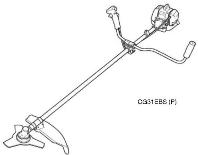
Drive shaft to engine (Fig. 1)
Loosen tube locking bolt (1) about ten turns so that the bolt point will not obstruct drive shaft tube to be inserted. When inserting drive shaft tube, hold the tube locking bolt outward preventing inside fitting from obstructing as well.
Some models may come with the drive shaft already installed.
NOTE
When it is hard to insert drive shaft up to the marked position on the drive shaft tube, turn drive shaft by the cutter mounting end clockwise or counter-clockwise. Tighten tube locking bolt lining up the hole in the shaft tube. Then tighten clamp bolt securely (1).
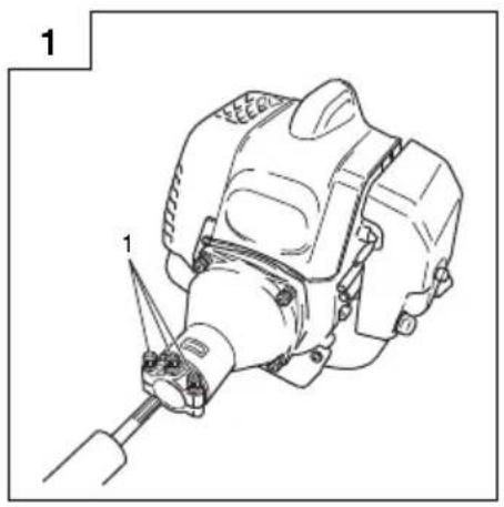
Installation of handle

When you use steel/rigid blades on straight shaft trimmers or brush cutters, always use a barrier bar (2) and shoulder harness with the loop handle. (Fig. 2)
Attach the handle to the drive shaft tube with the angle towards the engine.
Adjust the location to the most comfortable position before operation.
NOTE
If your unit has handle location label on drive shaft tube, follow indication.
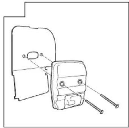
Remove the handle bracket (3) from the assembly. (Fig. 3)
Place the handles and attach the handle bracket with four bolts lightly. Adjust to appropriate position. Then attach it firmly with the bolts.
Attach the protection tube to the drive shaft or handle using cord clamps (4). (Fig. 4)
NOTE
If the protection tube is set apart from the handle or pipe, it will be caught by something during operation and it may cause serious injury. Do not set the protection tube apart from the handle or pipe.
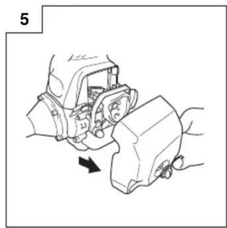
Throttle wire / stop cord
Remove air cleaner cover. (Fig. 5)
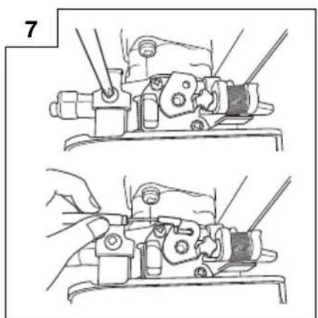
Loosen and remove the screw from the throttle wire holder. (Fig. 7)
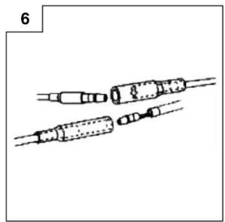
Connect the terminals of the stop cords coming out from the engine and shaft. (Fig. 6)
Hook the throttle wire end on the throttle of the carburetor.
Make sure that the throttle trigger shown in Fig. 18 has returned to the starting position.
Put the throttle outer end into the groove, and then cover it with the throttle wire holder and fix the holder with the screw. (Fig. 8)
Then, install the cleaner cover.
Fix the protection tube which the stop cords and throttle wire are passing through, on the pipe with the hip pad. Then, as shown in the figure, fix the protection tube on the pipe and handle with the bands in the bag.
After fixing, cut off the extra part of the band not to obstruct the operation. (Fig. 4)
NOTE
If the protection tube is set apart from the handle or pipe, it will be caught by something during operation and it may cause serious injury.
Do not set the protection tube apart from the handle or pipe.
Some models may come with the parts pre-installed.
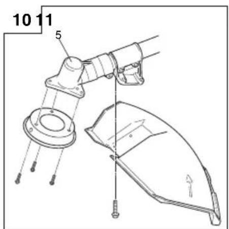
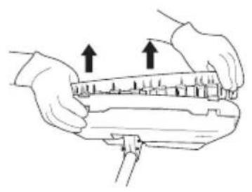
Installation of blade guard (Fig. 10)
The guard bracket already mounted to the drive shaft tube.
Attach the gear case cover with the three screws.
Install the blade guard on drive shaft tube against angle transmission (5). Tighten the guard bracket firmly so that the blade guard does not swing or move down during operation.
CAUTION
The blade guard must be in place during operation.
If the blade guard is not in place, there is a possibility of serious injury.
Blade guards are equipped with sharp line limiter. Be careful with handling it.
NOTE
- When attaching the guard extension to the blade guard, the sharp line limiter must be removed from the blade guard.
To remove the guard extension, refer to the drawings. Wear gloves as the extension has a sharp line limiter, then push the two square tabs on the guard one by one in order after removed the screw. (Fig. 12)
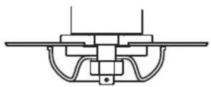
Installation of cutting blade (Fig. 13)
When installing a cutting blade, make sure that there are no cracks or any damage in it and that the cutting edges are facing the correct direction.
Align the notch hole of the cutter holder with the hole on the gear case (Top the gear case) and insert the Allen wrench to stop turning. Turn the fixing nut clockwise and remove the fixing nut, cutter holder cap, and toothed lock washers.
The installation of the cutting blade is as follows: insert the Allen wrench into the notch hole of the cutter holder and the hole on the gear case. Then, install the cutting blade (check the installing direction, as referring to Fig. 15), the cutter holder cap and toothed lock washers onto the cutter holder in this order. Finally, tighten the fi xing nut securely by turning counterclockwise with the Combi box spanner. (Fig. 13)
CAUTION
When installing the cutting blade, set its center hole to the convex part of the cutter holder and hold it with the concave surface of the cutter holder cap. Then, tighten the fixing nut to prevent the cutting blade from being eccentric. (Fig. 14)
After installing the cutting blade, be sure to remove the Allen wrench and Combi box spanner.
Before operation, make sure the blade has been properly installed.
Cutter holder cap under a cutting blade, check it for wear or cracks before operation. If any damage or wear replace it, as it is an article of consumption.
NOTE
The blade must be retained with a new cotter pin each time installed. (Fig. 13)
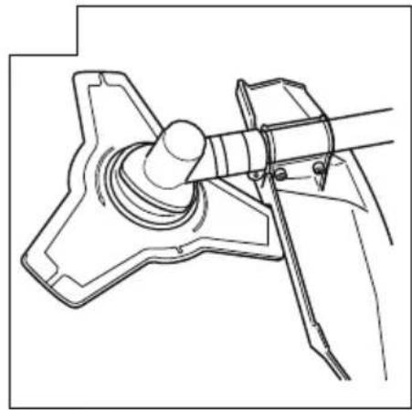
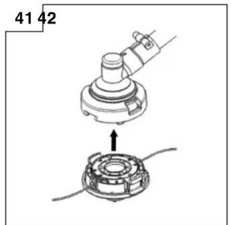
Installation of nylon head (Fig. 16)
Attach cutter holder (6) to the gear case. Insert an Allen wrench into the hole in the gear case to attach nylon head (7) by turning it clockwise.
NOTE
Since cutter holder cap is not used here, keep it for next metal blade use.
OPERATING PROCEDURES
Fuel (Fig. 17)

WARNING
The brush cutter is equipped with a two-stroke engine. Always run the engine on fuel, which is mixed with oil.
Provide good ventilation, when fueling or handling fuel.
- Fuel contains highly flammable and it is possible to get the serious personal injury when inhaling or spilling on your body. Always pay attention when handling fuel. Always have good ventilation when handling fuel inside building.
Fuel
Always use branded 89 octane unleaded gasoline.
Use genuine two-cycle oil or use a mix between 25:1 to 50:1, please consult the oil bottle for the ratio or Hitachi dealer.
If genuine oil is not available, use an anti-oxidant added quality oil expressly labeled for air-cooled 2-cycle engine use (JASO FC GRADE OIL or ISO EGC GRADE). Do not use BIA or TCW (2-stroke water-cooling type) mixed oil.
Never use multi-grade oil (10 W/30) or waste oil.
Always mix fuel and oil in a separate clean container.
Always start by filing half the amount of fuel, which is to be used. Then add the whole amount of oil. Mix (shake) the fuel mixture. Add the remaining amount of fuel.
Mix (shake) the fuel-mix thoroughly before filling the fuel tank.
Fueling
WARNING
Always shut off the engine before refueling.
Slowly open the fuel tank, when filling up with fuel, so that possible over-pressure disappears.
- Tighten the fuel cap carefully, after fueling.
Always move the brush cutter at least 3m from the fueling area before starting.
Always wash any spilled fuel from clothing soap.
Be sure to check for any fuel leakage after refueling.
Before fueling, clean the tank cap area caref no dirt falls into the tank. Make sure that the fuel is well mixed by shaking the container, before fueling.
Starting (Fig. 18)
CAUTION
Before starting, make sure the cutting attachment does not touch anything.
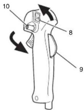
- Slide ignition switch (8) to RUN position. (Fig. 18)
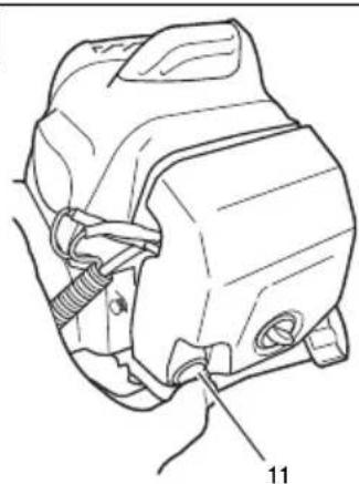
- Push priming bulb (11) several times so that fuel flows through return pipe. (Fig. 19)
- Set the throttle lever upward to the "idle" position. (Fig. 18)
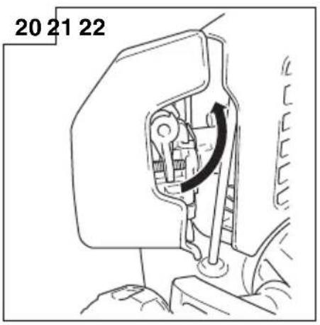
- Set choke lever to "START" position. (Fig. 20)
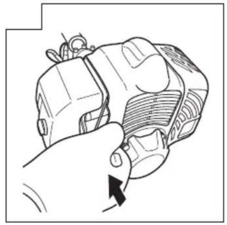
- Pull recoil starter briskly, taking care to keep the handle in your grasp and not allowing it to snap back. (Fig. 21)
- When you hear the engine want to start, return choke lever to RUN position (open). Then pull recoil starter briskly again.
NOTE
If engine does not start, repeat procedures from 2 to 5.
- After starting engine, pull throttle trigger to release throttle lock. Then allow the engine about 2-3 minutes to warm up before subjecting it to any load.
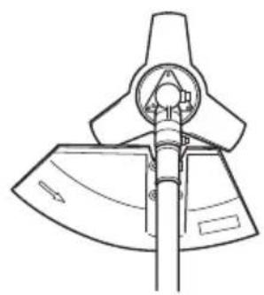
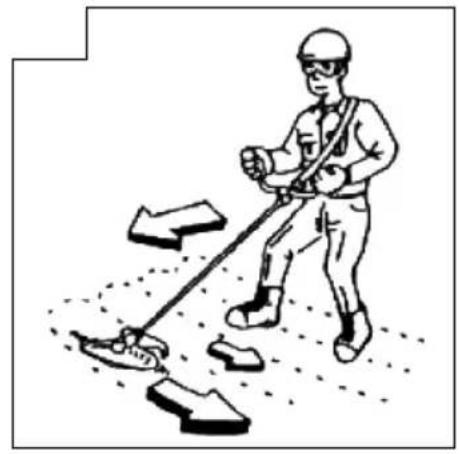
Cutting (Fig. 22, 23, 24)
- When cutting, operate engine at over 6500 rpm. Extended time of use at low rpm may wear out the clutch prematurely.
Cut grass from right to left. - Blade thrust may occur when the spinning blade contacts a solid object in the critical area.
A dangerous reaction may occur causing the entire unit and operator to be thrust violently. This reaction is called blade thrust. As a result, the operator may lose control of the unit which may cause serious or fatal injury. Blade thrust is more likely to occur in areas where it is difficult to see the material to be cut.
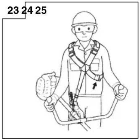
Wear the harness as shown in the figure. The blade turns counter-clockwise, therefore, be advised to operate the unit from right to left for efficient cutting. Keep onlookers out of working area at least 15m
NOTE
Press the quick release button or pull emergency release fl ap in the event of emergency. (Fig. 25)
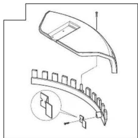
How to use the shoulder harness
Wear the shoulder harness on your shoulder as shown Fig. 23 and hook it on the hanger of the machine. Adjust the length of the shoulder harness to the most comfortable position. (Fig. 23)
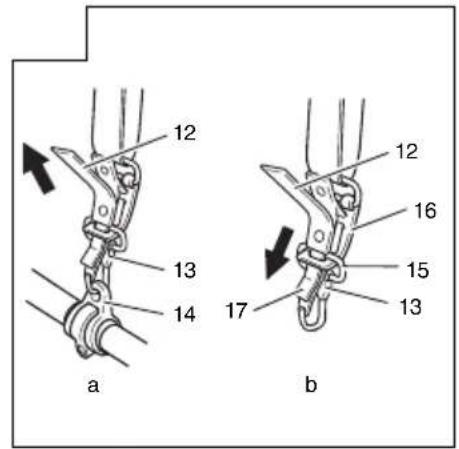
To remove the machine from the shoulder harness, hold the main pipe of the machine firmly by one hand and then remove the hook (13) of the shoulder harness from the hanger (14). (Fig. 25-a)
How to reinstall the hook after using the emergency release pinch
It needs to go through the buckle (15) of the hook (13) to the metal plate (16) on the harness and go through the plate (17) of the emergency release pinch to the metal plate (16) on the harness. (Fig. 25-b)
After installing the buckle onto the harness, pull the hook (13) and make sure the hook (13) is securely fixed on the harness, then hook it to the hanger (14). (Fig. 25-a)

WARNING
- When using the machine, wear the shoulder harness and hold the machine correctly with both hands.
If you feel that there is something dangerous, separate the brush cutter from your body by pulling the emergency release pinch (12) of the harness to the direction of the arrow shown in Fig. 25-a.
The bedding attachment should strike stones or other debris, stop the engine and make sure that the attachment and related parts are undamaged. When grass or vines wrap around attachment, stop engine and attachment and remove them.
, to ensure that
NOTE
If you pull the emergency release pinch without holding the machine, the machine will fall to your feet. Pull the emergency release pinch while holding the main pipe of the machine by one hand.
Before operation, make sure that the emergency release pinch on the shoulder harness is working properly.
Stopping (Fig. 26)
Decrease engine speed and run at an idle for a few minutes, then turn off ignition switch (8).

WARNING
A cutting attachment can injure while it continues to spin after the engine is stopped or power control is released. When the unit is turned off, make sure the cutting attachment has stopped before the unit is set down.
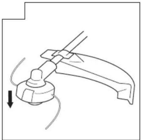
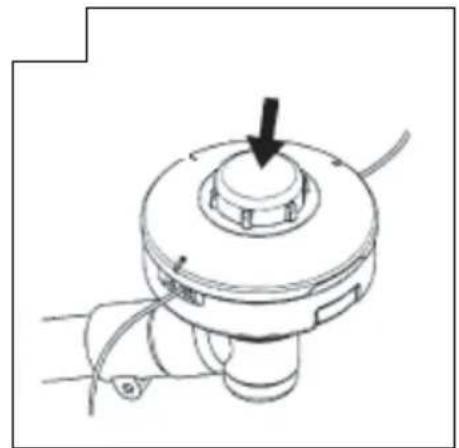
How to use nylon head
When cutting, operate engine at over 6500 rpm. Extended time of low rpm may wear out the clutch prematurely.
This product is designed so that it will stop cutting when the nylon line becomes 16 cm or longer.

WARNING
A cutting attachment can injure while it continues to spin after the engine is stopped or power control is released. When the unit is turned off, make sure the cutting attachment has stopped before the unit is set down.
Set the engine speed as low as possible and tap the Head on the ground. (Fig. 27) Also, you can extend nylon line with hands but the engine must be completely stopped. (Fig. 28)
Adjust nylon line to proper length 11-14 cm before each operation.
MAINTENANCE
MAINTENANCE, REPLACEMENT OR REPAIR OF THE EMISSION CONTROL DEVICES AND SYSTEMS MAY BE PERFORMED BY ANY NON-ROAD ENGINE REPAIR ESTABLISHMENT OR INDIVIDUAL.
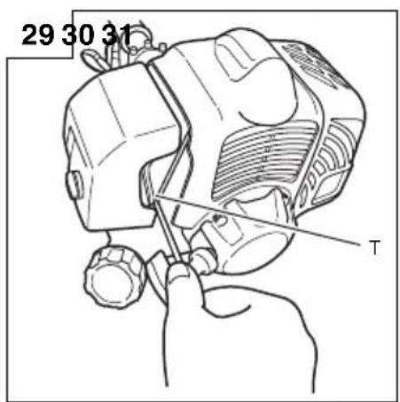
Carburetor adjustment (Fig. 29)
WARNING
The cutting attachment may be spinning during carburetor adjustments.
- Never start the engine without the complete clutch cover and tube assembled! Otherwise the clutch can come loose and cause personal injuries.
In the carburetor, fuel is mixed with air. When the engine is test run at the factory, the carburetor is basically adjusted. A further adjustment may be required, according to climate and altitude. The carburetor has one adjustment possibility:
T = Idle speed adjustment screw.
Idle speed adjustment (T)
Check that the air filter is clean. When the idle speed is correct, the cutting attachment will not rotate. If adjustment is required, close (clockwise) the T-screw, with the engine running, until the cutting attachment starts to rotate. Open (counter-clockwise) the screw until the cutting attachment stops. You have reached the correct idle speed when the engine runs smoothly in all positions well below the rpm when the cutting attachment starts to rotate.
If the cutting attachment still rotates after idle speed adjustment, contact your Hitachi dealer.
NOTE
Standard Idle rpm is 2200-2800 rpm.
WARNING
When the engine is idling the cutting attachment must under no circumstances rotate.
Air filter (Fig. 30)
The air filter must be cleaned from dust and dirt in order to avoid:
Carburetor malfunctions
Starting problems
Engine power reduction
Unnecessary wear on the engine parts
Abnormal fuel consumption
Clean the air filter daily or more often if working in exceptionally dusty areas.
Cleaning the air filter
Remove the air filter cover and the filter (18). Rinse it in warm soap suds. Check that the filter is dry before reassembly. An air filter that has been used for some time cannot be cleaned completely. Therefore, it must regularly be replaced with a new one. A damaged filter must always be replaced.
Fuel filter (Fig. 31)
Drain all fuel from fuel tank and pull fuel filter line from tank. Pull fi lter element out of holder assembly and rinse element in warm water with detergent.
Rinse thoroughly until all traces of detergent are eliminated. Squeeze, do not wring, away excess water and allow element to air dry.
NOTE
If element is hard due to excessive dirt buildup, replace it.
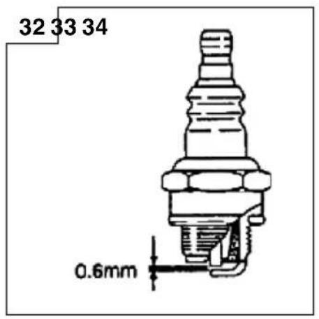
Spark plug (Fig. 32)
The spark plug condition is influenced by:
An incorrect carburetor setting
Wrong fuel mixture (too much oil in the gasoline)
A dirty air filter
Hard running conditions (such as cold weather)
These factors cause deposits on the spark plug electrodes, which may result in malfunction and starting difficulties. If the engine is low on power, difficult to start or runs poorly at idling speed, always check the spark plug first. If the spark plug is dirty, clean it and check the electrode gap. Re-adjust if necessary. The correct gap is 0.6mm . The spark plug should be replaced after about 100 operation hours or earlier if the electrodes are badly eroded.
Muffler (Fig. 33)
Remove the muffler and clean out any excess carbon from the exhaust port or muffler inlet every 100 hours of operation.
Cylinder (Engine cooling) (Fig. 34)
The engine is air cooled, and air must circulate freely around engine and over cooling fins on cylinder head to prevent overheating.
Every 100 operating hours, or once a year (more often if conditions require), clean fins and external surfaces of engine of dust, dirt and oil deposits which can contribute to improper cooling.
NOTE
Do not operate engine with engine shroud or muffler guard removed as this will cause overheating and engine damage.
Angle transmission (Fig. 35)
Check angle transmission or angle gear for grease level about every 50 hours of operation by removing the grease filler plug on the side of angle transmission.
If no grease can be seen on the flanks of the gears, fill the transmission with quality lithium based multipurpose grease up to 3/4. Do not completely fill the transmission.
Blade

WARNING
Wear protective gloves when handling or performing maintenance on the blade. (Fig. 36)
Use a sharp blade. A dull blade is more likely to snag and thrust. Replace the fastening nut if it is damaged and hard to tighten.
When replacing blade, purchase one recommended by Hitachi, with a 25.4 mm (one inch) fitting hole.
When installing a saw blade, always face the stamped side up. In the case of a 3 tooth blade, it can be used on either side.
Use the correct blade for the type of work.
When replacing blades, use appropriate tools.
When cutting edges become dull, re-sharpen or file as shown in the illustration. Incorrect sharpening may cause excessive vibration.
Discard blades that are bent, warped, cracked, broken or damaged in any way.
NOTE
When sharpening blade it is important to maintain an original shape of radius at the base of the tooth to avoid cracking.
Nylon head
Nylon line replacement
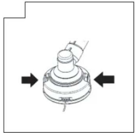
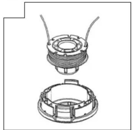
Remove the cutting body cap by pushing inward the locking tabs on the side of the nylon head (Fig. 37). Take out the spool, hook the new nylon line into the hole of the spool, then wind it around the spool in two stages (Fig. 38).
When the nylon line has been wound around the spool, temporarily fasten it in the opening of the spool at about 10cm from the end. (Fig. 39) Then thread the nylon line through the hole on the side of the nylon head and place the cutting body cap in reverse order of the cap removal. Pull the right and left nylon lines until they are secured about 11 - 14cm from the end. (Fig. 42)
NOTE
The nylon head is designed for nylon lines with an outer diameter of 2.4mm . Do not use nylon lines with a different outer diameter.
Make sure that the right and left nylon lines are of equal length since vibrations will otherwise increase.
Maintenance schedule
Below you will find some general maintenance instructions. For further information please contact your Hitachi dealer.
Daily maintenance
Clean the exterior of the unit.
Check that the harness is undamaged.
Check the blade guard for damage or cracks. Change the guard in case of impacts or cracks.
Check that the cutting attachment is properly centred, sharp, and without cracks. An off-centre cutting attachment induces heavy vibrations that may damage the unit.
Check that the cutting attachment nut is sufficiently tightened.
Make sure that the blade transport guard is undamaged and that it can be securely fitted.
Check that nuts and screws are sufficiently tightened.
Weekly maintenance
Check the starter, especially the cord and return spring.
Clean the exterior of the spark plug.
Remove it and check the electrode gap. Adjust it to 0.6mm or change the spark plug.
Clean the cooling fins on the cylinder and check that the air intake at the starter is not clogged.
Check that the angle gear is filled with grease up to 3/4.
Clean the air filter.
Monthly maintenance
Rinse the fuel tank with gasoline.
Clean the exterior of the carburetor and the space around it.
Clean the fan and the space around it.
SYMBOLBEDEUTUNGEN
WAARSCHUWINGEN EN VEILIGHEIDSINSTRUCTIES 40
SPECIFICATIONS. 41
MONTAGEPROCEDURES 42
BEDIENING 43
ONDERHOUD 44
WAT IS WAT
WAARSCHUWINGEN EN VEILIGHEIDSINSTRUCTIES
Cortar (Fig. 22, 23, 24)
| Item No. | Part Name Q'TY | |
| 1 Ball bearing, 6001 2 | ||
| 2 Oil seal TC type 12 x 28 x 7 1 | ||
| 3 Oil seal TC type 12 x 22 x 7 1 | ||
| 4 Retaining ring RTW-28 1 | ||
| 5 Crank case set 1 | ||
| 5-3 Spring type straight pin slotted 3 x 10 2 | ||
| 5A Crank Case Ass'y 1 | ||
| 6 Gasket, crankcase 1 | ||
| 7 Cross recessed pan head screw S M5 x 25 4 | ||
| 8-1 Piston 1 | ||
| 8-2 Ring, piston | 2 | |
| 8-3 Pin, piston 9 x 31 | 1 | |
| 8-4 Ring, snap | 2 | |
| 8-7 Crank shaft assy | 1 | |
| 9 | Woodruff key 3 x 3.7 x 10 | 1 |
| 10 | Cylinder | 1 |
| 11 | Gasket, cylinder | 1 |
| 12 Torx socket head cap screw M5 x 0.8 x 20 | 4 | |
| 13B | Spark plug | 1 |
| 14-1 | Rotor, magnet | 1 |
| 14-2 | Coil comp | 1 |
| 15 Conical nut M8 x P1.25 1 | ||
| 16 Washer, ig coil 4.2 x 10 x 1 | 2 | |
| 17 | Spacer, ig coil | 2 |
| 18 | Torx socket head cap screw PS M4 x 0.7 x 20 with nylok | 2 |
| 19 Wire, lead | 1 | |
| 20B | Wire, lead-ground 1 | |
| 21 | Sleeve, leadwire | 1 |
| 22 Clutch assy | 1 | |
| 23 Clutch bolt | 2 | |
| 24 | Wave washer 10 | 2 |
| 25 | Washer 8.2 x 18 x 1.2 | 2 |
| 26 | Fan cover for back pack | 1 |
| 27 | Spring type staight pin slotted 3 x 10 | 2 |
| 28 | Cross recessed pan head screw PS M5 x 25 | 4 |
| 29B | Muffler assy rear exhaust with catalyst | 1 |
| 30 Heat shield | 1 | |
| 31 | Gasket, muffler | 1 |
| 32 | Torx socket button head screw M5 x 0.8 x 60 | 2 |
| 33 | Cross recessed pan head screw PS M5 x 16 | 2 |
| 34 | Muffler cover | 1 |
| 35 Gasket, insulator | 1 | |
| 36 | Insulator for diaphragm carb. | 1 |
| 37 | Torx socket button head screw PS M5 x 0.8 x 22 | 2 |
| 38 Gasket, carburetor | 1 | |
| 39 | Carburetor assy , diaphragm | 1 |
| 40 Gasket, cleaner | 1 | |
| 41-1 | Base, cleaner | 1 |
| 41-2 | Primer pump assy. | 1 |
| 41-3 | Pipe, pump (0.045 m) | 1 |
| 41-4 | Clip, pipe | 1 |
| 41-5 | Clip, pipe | 1 |
| 41-6 | Pipe, return | 1 |
| 42 | Torx socket button head screw M5 x 0.8 x 60 | 2 |
| Item No. | Part Name Q'TY | |
| 43 Spit | back shield | 1 |
| 44 | Air filter element | 1 |
| 45-1 | Cover, cleaner | 1 |
| 45-2 | Knob, cover | 1 |
| 46 Top | cover | 1 |
| 47 Spacer, top cover | 1 | |
| 48 | Cross recessed pan head screw PS M5 x 20 | 1 |
| 49-1-1 | Fuel tank | 1 |
| 49-1-2 | Fuel filter comp | 1 |
| 49-1-3 | Pipe, suction (0.150 m) | 1 |
| 49-1-4 | Clip, pipe | 1 |
| 49-1-5 | Valve Ass'y | 1 |
| 49-1-5-1 | Valve, fuel cap | 1 |
| 49-1-5-2 | Cap, holder | 1 |
| 49-1-5-3 | Holder, valve | 1 |
| 49-1-5-4 | Element, valve | 1 |
| 49-1-5-5 | Pipe, valve assy | 1 |
| 49-2 | Fuel Cap Ass'y | 1 |
| 49-2-1 | Fuel cap | 1 |
| 49-2-2 | Gasket, fuel cap | 1 |
| 49-2-3 | Holder, Gasket 1 | |
| 49-2-4 | Strap, fuel cap | 1 |
| 50 Engine stand | 1 | |
| 51 | Torx socket flange screw M5 x 0.8 x 16 | 2 |
| 52 | Cross recessed pan head screw PS M5 x 20 | 1 |
| 53 | Recoil starter assy | 1 |
| 54 Pulley assy | 1 | |
| 55 | Cross recessed pan head screw PS M5 x 25 | 4 |
| 56 Stay,throttle cable | 1 | |
| 57 | Cross recessed pan head screw ST4.2 x 12 1 |

CG 31EBS(P)
| Item No. | Part Name Q'TY | |
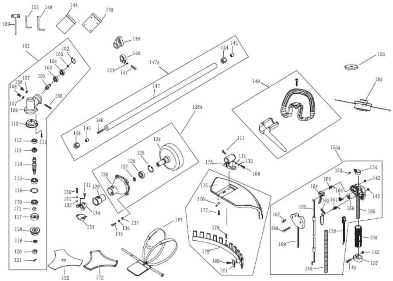
| 101 Gear case ass'y 1 | ||
| 102 Stop ring 1 | ||
| 103 Stop ring (Φ10) 1 | ||
| 104 Bearing (6000-2RS/P5) 2 | ||
| 105 Pinion 1 | ||
| 106 Screw (M5 x 25) 1 | ||
| 107 Washer 2 | ||
| 108 Bolt (M6 x 12) 2 | ||
| 109 Gear case 1 | ||
| 110 Safety guard 1 | ||
| 111 Screw (M5 x 12) 5 | ||
| 112 Bearing (6000/P5) | 1 | |
| 113 Gear | 1 | |
| 114 | Gear shaft | 1 |
| 115 | Bearing (6002-2RS/P5) | 1 |
| 116 Stop ring (Φ32) | 1 | |
| 117 | Holder A | 1 |
| 118 | Holder B | 1 |
| 119 | Nut Cover | 1 |
| 120 Washer 1 | ||
| 121 Left nut (M10 x 1.25) | 1 | |
| 122 Pin (2 x 16) | 2 | |
| 123 Washer5 1 | ||
| 124 Clutch drum comp | 1 | |
| 125 Stop ring (Φ35) | 1 | |
| 126 Bearing (6202-2RS/P5) | 1 | |
| 127 Stop ring (Φ15) | 1 | |
| 128 Clutch case | 1 | |
| 128A | Clutch case Ass'y | 1 |
| 129 Rubber cover | ||
| 130 Screw (M5 x 25) 2 | ||
| 131 S. washer (Φ5) | 4 | |
| Item No. | Part Name Q'TY | |
| 132 Washer (Φ5) | 4 | |
| 133 Clamp B | 1 | |
| 134 Clamp A | 1 | |
| 135 Screw (M6 x 20) 4 | ||
| 136 S washer (Φ6) | 4 | |
| 137 Washer (Φ6) | 4 | |
| 138 Tool kit | 1 | |
| 139 Hanger | 1 | |
| 140 Clamp | 1 | |
| 141 Screw (M5 x 20) 1 | ||
| 142 Nut (M5) | 1 | |
| 143 kit | 1 | |
| 144 Bushing cover | 6 | |
| 145 Oil-bearing (8 x 14 x 14) 6 | ||
| 146 Drive shaft (1526 mm) | 1 | |
| 147 Pipe (26 x 1.5 x 1500) | 1 | |
| 147A Pipe Ass'y 1 | ||
| 148 Belt assay | 1 | |
| 149 Wire clamp band | 2 | |
| 150 Screw (M6 x 40) 4 | ||
| 151 Cap(lower) | 1 | |
| 152 Rubber cover | 1 | |
| 153 Nut (M6) | 4 | |
| 154 Bracket 1 | ||
| 155 Nut M6 | 4 | |
| 156 Cap_upper | 1 | |
| 157 Screw x (M6 x 25) | 4 | |
| 158 Handle (Bike) | 1 | |
| 159 Grip | 1 | |
| 160 Bushing | 1 | |
| 161 inner spanner S=5 | 1 | |
| 162 Screw (ST2.9 x 10) | 1 | |
| Item No. | Part Name Q'TY | |
| 163 Buthon | 1 | |
| 164 Spring | 1 | |
| 165 Stop Switch | 1 | |
| 166 Locking pin | 1 | |
| 167 Throttle lever | 1 | |
| 168 Spring | 1 | |
| 169 Box, right | 1 | |
| 169A R Switch Ass'y | 1 | |
| 170 BOLT ST3.5 x 16 | 2 | |
| 171 Screw (M5 x 30) 3 | ||
| 172 Cable comp | 1 | |
| 173 Stop wire | 1 | |
| 174 Safety lever | 1 | |
| 175 Spring | 1 | |
| 176 Box, left | 1 | |
| 177 Blade | 1 | |
| 178 Blade cover | 1 | |
| 179 \afety guard bracket 1 | ||
| 180 Tube | 1 | |
| 181 \afety guard 1 | ||
| 182 Spacer | 2 | |
| 183 Screw (M5 x 16) 4 | ||
| 184 Screw (ST4.2 x 16) | 1 | |
| 185 Guard | 1 | |
| 186 Screw (ST4.2 x 12) | 2 | |
| 187 Blade | 1 | |
| 188 Cutting head assy | 1 | |
| 189 Nylon cutter head guard | 1 | |
| 190 Oil seal | 1 | |
| 191 Inner spanner S=4 | 1 | |
| 192 Spark plug sleeve | 1 |
CG 31EBS(LP)
| Item No. | Part Name Q'TY | |
| 101 Gear case ass'y 1 | ||
| 102 Stop ring 1 | ||
| 103 Stop ring (Φ10) 1 | ||
| 104 Bearing (6000-2RS/P5) 2 | ||
| 105 Pinion 1 | ||
| 106 Screw (M5 x 25) 1 | ||
| 107 Washer 2 | ||
| 108 Bolt (M6 x 12) 2 | ||
| 109 Gear case 1 | ||
| 110 Safety guard 1 | ||
| 111 Screw (M5 x 12) 5 | ||
| 112 Bearing (6000/P5) | 1 | |
| 113 Gear | 1 | |
| 114 | Gear shaft | 1 |
| 115 | Bearing (6002-2RS/P5) | 1 |
| 116 Stop ring (Φ32) | 1 | |
| 117 | Holder A | 1 |
| 118 | Holder B | 1 |
| 119 | Washer | 1 |
| 120 Left nut (M10 x 1.25) | 1 | |
| 121 Pin (2 x 16) | 2 | |
| 122 Blade | 1 | |
| 123 Washer5 1 | ||
| 124 Clutch drum comp | 1 | |
| 125 Stop ring (Φ35) | 1 | |
| 126 Bearing (6202-2RS/P5) | 1 | |
| 127 Stop ring (Φ15) | 1 | |
| 128 Clutch case | 1 | |
| 128A | Clutch case Ass'y | 1 |
| 129 Rubber cover | 1 | |
| 130 Screw (M5 x 25) 2 | ||
| 131 S. washer (Φ5) | 4 | |
| Item No. | Part Name Q'TY | |
| 132 Washer (Φ5) | 4 | |
| 133 Clamp B | 1 | |
| 134 Clamp A | 1 | |
| 135 Screw (M6 x 20) 4 | ||
| 136 S washer (Φ6) | 4 | |
| 137 Washer (Φ6) | 4 | |
| 138 Tool kit | 1 | |
| 139 Hanger | 1 | |
| 140 Clamp | 1 | |
| 141 Screw (M5 x 20) 1 | ||
| 142 Nut (M5) | 3 | |
| 143 kit | 1 | |
| 144 Bushing cover | 6 | |
| 145 Oil-bearing (8 x 14 x 14) 6 | ||
| 146 | Drive shaft(1526 mm Korea) | 1 |
| 147 Pipe (26 x 1.5 x 1500) | 1 | |
| 147A | Pipe Ass'y (Euro) | 1 |
| 148 inner spanner S=5 | 1 | |
| 149 Handle Ass'y | 1 | |
| 150 Nylon cutter head guard | 1 | |
| 152 Inner spanner S=4 | 1 | |
| 153 Screw (M5 x 14) 1 | ||
| 154 Clamp | 1 | |
| 155 Box, right | 1 | |
| 155A | Loop Switch Ass'y | 1 |
| 156 Rubber cover | 1 | |
| 157 Clamp | 1 | |
| 158 Stop button comp | 1 | |
| 159 Tire | 1 | |
| 160 Spring | 1 | |
| 161 Spring | 1 | |
| Item No. | Part Name Q'TY | |
| 162 | Safety lever | 1 |
| 163 | Spring | 1 |
| 164 | Throttle lever | 1 |
| 165 | Cable comp | 1 |
| 166 | Tube | 1 |
| 167 | Screw (M5 x 20) 1 | |
| 168 | Screw (M5 x 30) 3 | |
| 169 | Box, left | 1 |
| 170 | Oil seal | 1 |
| 171 | Bushing | 1 |
| 172 | Blade cover | 1 |
| 173 | Safety guard bracket 1 | |
| 175 | Safety guard 1 | |
| 176 | Spacer | 2 |
| 177 | Screw (M5 x 16) 4 | |
| 178 | Screw (ST4.2 x 16) | 1 |
| 179 | Guard 1 | |
| 180 | Screw (ST4.2 x 12) | 2 |
| 181 | Blade | 1 |
| 182 | Spark plug sleeve | 1 |
| 183 | Belt assy | 1 |
| 184 | Cutting head assy | 1 |


| English EC | DECLARATION OF CONFORMITY Nederlands EC VER | KlarING VAN | CONFORMITEIT |
| (Applies to Europe only)We declare under our sole responsibility that this product is in conformity with Council Directive 98/37/EC, 2004/108/EC and 2000/14/EC. This product also complies with the essential requirements of 2006/42/EC to be applied from 29 December 2009 instead of 98/37/EC.The following standards have been taken into consideration.ISO 7112/7113/7916/7917/7918/8380/11682 (EN ISO 12100-2, EN ISO 11806)Annex V. For information relating to noise emissions, see the chapter specifi cations.The European Standards Manager at Hitachi Koki Europe Ltd. is authorized to compile the technical fi le. | (Declaraciones del viento de la viento de la viento de la viento de la viento de la viento de la viento de la viento de la viento de la viento de la viento de la viento de la viento de la viento de la viento de la viento de la viento de la viento de la viento de la viento de la viento de la viento de la viento de la viento de la viento de la viento de La CE) | (Geldt alleen voor Europa)Wij verklaren onder eigentje verantwoordelijkheid dat dit product voldoet aan de richtlij 98/37/EC, 2004/108/EC en 2000/14/EC.Dit product voldoet ook aan de essentièle vereisten van 2006/42/ECtoegepast vanaf de 2009, inplaats van 98/37/EC.De volgende standaards zijn toegepast.ISO 7112/7113/7916/7917/7918/8380/11682 (EN ISO 12100-2, EN ISO 11806)A anvulling V. Voor informatie over de verwezen aan het hoofdstuk met de specifici caties.De manager voor Europees normen van Hitachi Koki Europe Ltd.heeft de bevoedheid tot het samenstellen van het technische bestand. | |
| Deutsch | ERKLÄRUNG ZUR KONFORMITÄT MIT CE-REGELN Espanol DECLARACION DE CONFORMIDAD DE LA CE | ||
| (Gilt nur für Europa)Wir erklären eigenverantwortlich, dass dieses Produkt den Bestimmungen der Richtlinien 98/37/EG, 2004/108/EG und 2000/14/EG des Europäischen Rates entspricht. Desses Produkt entspricht auch den wesentlichen Anforderungen der Richtlinie 2006/42/CE, die ab 29. Dezember 2009statt 98/37/CEin Kraft ist.Die nachfolgenden Standards wurden in Betracht gezogen.ISO 7112/7113/7916/7917/7918/8380/11682 (EN ISO 12100-2, EN ISO 11806)Anhang V. Informationen zur Geräuschentwicklung finden Sie im Kapitel Spezifizierungen.Der Manager für europäische Standards bei der Hitachi Koki Europe Ltd. ist zum Verfassen der technischen Daten bei betrug. | (De aplicacionsole en Europa)Declaramos bajo esta exclusiva responsabilitad que este producto es conforme con las Directivas 98/37/CE, 2004/108/CEy 2000/14/CE. Este producto también cumple con los requisitos esencias de 2006/42/CE aplicables desde el 29 de diciembre de 2009 en lugar de 98/37/CE.Se han tenido en consideracion las��entes normas.ISO 7112/7113/7916/7917/7918/8380/11682 (EN ISO 12100-2, EN ISO 11806)Anexo V. Para mayor informacion sobre la emision de ruidos, consulte la seccion de specifici caciones.El Jefe de Normas Europeas de Hitachi Koki autorizzato para recopilar ARCHivos técnicos. | ||
| Français | DECLARATION DE CONFORMITE CE Portugueses DECLARACION DE CONFORMIDADE CE | ||
| (Cocerne l'Europe uniquement)Nos déclarons sur la foit de notre seule responsabilité que ce produit est conforme aux dispositions des Directives du Conseil de l'Union europeenne 98/37/EC, 2004/108/EC et 2000/14/EC.Ce produit est également conforme aux exigencies essentielles de 2006/42/CE applicables a compter du 29 Décembre 2009 en lieu et place de celle de 98/37/CE.Les normes suivantes ont ete prises en considération.ISO 7112/7113/7916/7917/7918/8380/11682 (EN ISO 12100-2, EN ISO 11806)Annexe V. Pour les informations relatives aux émissions de bruits, reportez-vous au chapitre Caracteristiques.Le responsable des normes européennes d'Hitachi Koki Europe Ltd. est autorisé à compiler les données techniques. | (Aplica-se apenas à Europa)Declaramos para os devidos efelitos que este producto cumpre os requisitos das directivas comunitárias 98/37/CE, 2004/108/CE e 2000/14/CE. Este producto también está em conformidade com os requisitos esenciais da 2006/42/CE, a serem aplicados a partir de 29 de Dezembro de 2009 em substituicao da 98/37/CE.As segunte normas harmonizadas foram aplicadas.ISO 7112/7113/7916/7917/7918/8380/11682 (EN ISO 12100-2, EN ISO 11806)Anexo V. Para obter mais informacoes relacionadas com emissoes de ruido, consulte aspecifica caçoes do capitol.O Gestor de Normas Europeias da Hitachi Koki Europe autorizzato a compiler o fi chiero técuno. | ||
| Italiano | DICHIAZAIONE DI CONFORMITÀ CE(Si applica solo all'Europa)Dichiariamo molto la nostra esclusiva responsabilità che questo prodotto è conforme alle Dirette del Consiglio 98/37/CE, 2004/108/CE e 2000/14/CE.Qesso prodotto è conformeanche al requisiti 2006/42/CE vigentia a partire dal 29 dicembre 2009 inceve dei requisiti 98/37/CE.Sono stati presi in considerazione i seguito standard.ISO 7112/7113/7916/7917/7918/8380/11682 (EN ISO 12100-2, EN ISO 11806)Alle gato V. Per informazioni riguardo alle consultare le specifiche che del capitolo.II Responsabile delle Norme Europee di Hitachi Koki Ltd. è autorizzato a compilerare la schedea的技术ica. | emission di rumore, | |
| Representative offi ce in EuropeHitachi Power Tools Europe GmbHSiemensring 34, 47877 Willich 1, F. R. GermanyTechnical file at:Hitachi Koki Europe Ltd.Clonshaugh Business & Technology Park, Dublin 17, IrelandHead offi ce in JapanHitachi Koki Co., Ltd.Shinagawa Intercity Tower A, 15-1, Konan 2-chome,Minato-ku, Tokyo, Japan | CE31.1.2011F.TashimoF.TashimoVice-President & Director |