
SC5032 - Air Conditioning QLIMA - Free user manual and instructions
Find the device manual for free SC5032 QLIMA in PDF.
| Product type | Split air conditioner (indoor and outdoor units) |
| Brand | Qlima |
| Model | SC5032 |
| Power supply | 220-240 V ~ 50 Hz |
| Rated current | Up to 16 A (depending on power) |
| Recommended cable cross-section | 2.5 mm² |
| Required electrical protection | Residual-current circuit breaker and suitable fuse |
| Refrigerant | See nameplate (type and factory charge for 4 m of piping) |
| Pre-installed piping length | 4 m (factory pre-charged) |
| Electrical connections between units | Quick connectors (SC5xxx) |
| Main functions | Cooling, heating, ventilation, dehumidification (depending on mode) |
| Remote control included | Yes |
| Wireless smart kit included | Yes |
| Installation | Only by certified professional |
| Maintenance and cleaning | Regular filter cleaning; annual inspection by professional |
| Safety | Mandatory grounding; do not install yourself; use dedicated circuit |
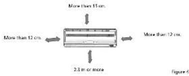
| Indoor unit clearances | 12 cm sides, 15 cm ceiling, 2.3 m minimum height |
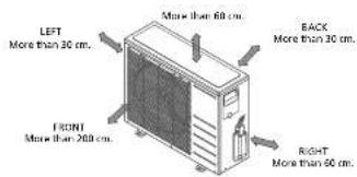
| Outdoor unit clearances | 30 cm rear/left, 200 cm front, 60 cm right side |
| Repairability | Spare parts available via after-sales service; warranty does not cover incorrect installation |
Frequently Asked Questions - SC5032 QLIMA
User questions about SC5032 QLIMA
0 question about this device. Answer the ones you know or ask your own.
Ask a new question about this device
Download the instructions for your Air Conditioning in PDF format for free! Find your manual SC5032 - QLIMA and take your electronic device back in hand. On this page are published all the documents necessary for the use of your device. SC5032 by QLIMA.
USER MANUAL SC5032 QLIMA
natural_image
Exterior view of a Qlima air conditioner unit (no visible text or symbols on the fan or background)| E | MANUAL DE INSTALACIÓN | 2 |
| F | MANUEL D'INSTALLATION | 22 |
| GB | INSTALLATION MANUAL | 44 |
| I | MANUALE DI INSTALLAZIONE | 62 |
| NL | INSTALLATIEHANDLEIDING | 82 |
| PL | INSTRUKCJA MONTAŻUW | 102 |
| P | MANUAL DE INSTALAÇÃO | 124 |
| SLO | PRIROČNIK ZA NAMESTITEV | 144 |
AVISO IMPORTANTE:

ATENCIÓN


5(C)5x32/SC4132

5(C)5x48/SC4148


ATTENTION
5(C)5x32/SC4132
5(C)5x48/SC4148


ATTENTION
Install this device only when it complies with local/national legislation, ordinances and standards. This product is intended to be used as an air conditioner in residential houses and is only suitable for use in dry locations, in normal household conditions, indoors in living room, kitchen and garage. Check the mains voltage and frequency. This unit is only suitable for earthed sockets, connection voltage 220-240 V\~/50 Hz. Model SC41xx & SC5xxx has to be connected directly to the supply source.
This installation manual is intended for use by individuals possessing adequate backgrounds of electrical, electronic, refrigerant and mechanical experience. Any attempt to install or repair the appliance may result in personal injury and property damage. The manufacturer or seller cannot be responsible for the interpretation of this information, nor can it assume any liability in connection with its use.
The information, specifications and parameter are subject to change due to technical modifications or improvement without any prior notice. The accurate specifications are presented on the nameplate label.
- Please read this installation manual completely before installing the product.
- When the power cord is damaged, replacement work shall be performed by authorized personnel only.
- Installation work must be performed in accordance with all European, national and/or local directives and standards and must be done by authorized personnel only. The guarantee is invalid for damage caused by neglect or by actions that deviate from those in this instruction booklet.
- Always make sure to wear the correct personal safety protections such as protective eyewear, gloves, mouthcaps, ear protection etc.
Internet:
For your convenience you can download the latest version of the user-, installation- and/or service manual on www.qlima.com

WARNING!
Do not install, remove and/or reinstall the unit by yourself if you do not have the adequate electrical, electronic, refrigerant, mechanical experience and authorisation.
- Improper installation can cause water leakage, electrical shock, refrigerant leakage or fire. Please consult authorized dealer or specialized air conditioner engineer for the installation work. Please note faults caused by improper installation is not covered by warranty.
- Unit must be installed in an easily accessible area. Any additional cost required to hire special equipment to service the unit will be the responsibility of the customer
CONTENT
- Safety precautions
- Items packed with the unit
2.1 items packed with the unit (for SC41xx & SC5xxx models)
2.2 items packed with the unit (for S41xx & S5xxx models) - Activities for installing the air conditioner for the SC41xx & SC5xxx models.
- Activities for installing the air conditioner for the S41xx & S5xxx models.
- Determining the location of the inside and outside unit.
5.1 Determining the location of the inside and outside unit for the S41xx, S5xxx, SC41xx & SC5xxx models.
5.2 Determining the location of the exterior unit for the S41xx, S5xxx, SC41xx & SC5xxx models. - Possibilities for installing the piping from the interior unit to The exterior unit.
- Mounting the installation plate and making the piping feedthrough.
7.1 Mounting the installation plate of the interior unit.
7.2 Drilling the piping, condensation hose and cable feed-through. - Connection the coolant pipes.
8.1 Connecting and disconnecting the coolant pipes for the SC41xx & SC5Xxx models.
8.2 Connecting the coolant pipes for the S41xx & S5xxx models. - Connection the condensation drainage hose for the S41xx, S5xxx, SC41xx & SC5xxx models.
9.1 Connection the condensation drainage hose to the interior unit.
9.2 Drain joint installation. - Electrical work.
- Connecting the electrical cables.
11.1 Connecting the electrical cables for the SC41xx & SC5xxx models.
11.2 Connecting the electrical cables for the 541xx & 55xxx models. - Evacuating the cooling system of the 541xx & 55xxx models.
- Checking the cooling system for leakage on the S41xx, S5xxx, SC41xx & SC5xxx models.
- Topping up coolant for piping lengths above 05 metres.
- Test running after installation.
GB
42
GB
43
1. SAFETY PRECAUTIONS
The following should be always observed for safety:
• Be sure to read the following WARNING before installing the airconditioner.
- Be sure to observe the cautions specified here as they include important items related to safety.
- After reading this instructions, be sure to keep it together with the owners manual in a handy place for future reference.
The air conditioner contains a refrigerant and can be classified as pressurized equipment. Therefore always contact an authorized air conditioning engineer for installation and maintenance of the air conditioner. The air conditioner must be inspected and serviced on an annual base by an authorized air conditioning engineer.

WARNING
Do not install it yourself.
- Incorrect installation could cause injury due to fire, electric shock, the unit falling or leakage of water. Consult your dealer from whom you purchased the unit or an authorised installer.
Install the unit securely in a place which can bear the weight of the unit. - When installed in an insufficiently strong place, the unit could fall causing injury.
Use the specified electrical wires to connect the indoor and outdoor units securely and attach the wires firmly to the terminal board connecting sections so the stress of the wires is not applied to the sections.
- Incorrect connection and fixing could cause a fire.
Be sure to use the provided or specified parts for the installation work.
- The use of defective parts could cause an injury due to a fire, electric shock, the unit falling, etc.
Perform the installation securely referring to the installation instruction. - Incorrect installation could cause a personnel injury due to fire, electric shock, the unit falling or leakage of water.
Perform electrical work according to the installation manual and be sure to use an exclusive circuit. - If the capacity of the power circuit is insufficient or there is incomplete electrical work, it could result in a fire or an electric shock.
Check that the refrigerant gas does not leak during installation or after installation is completed. - Leaking refrigerant is bad for the environment and could cause global warming.
Attach the electrical part cover to the indoor unit and the service panel to the outdoor unit securely. - If the electrical part covers off the indoor unit and/or the service panel of the outdoor unit are not attached securely, it could result in a fire or electrical shock due to dust, water, etc.
GB
44

CAUTIONS
- This equipment must be earthed. It can possibly cause electrical shock if grounding is not perfect. Do not use an extension cable. Otherwise it can cause electric fire or shock.
- The mains supply in the house must be equipped with an earth leak switch. If it is not equipped with an earth leak switch this could result in electrical shocks and fire.
Perform the drainage/piping work according to the installation instruction.
- If there is a defect in the drainage/ piping work, water could leak from the unit and household goods could get wet and be damaged.
2. ITEMS PACKED WITH THE UNIT
2.1 ITEMS PACKED WITH THE UNIT (for SC41xx & SC5xxx models)
| Number Name of Accessories Quantity | ||
| 1 Installation plate 1 | ||
| 2 Clip Anchor 8 | ||
| 3 Self-tapping screw 'A' ST 3.9x25 8 | ||
| 4 Seal 1 | ||
| 5 Drain joint 1 | ||
| 6 Connecting pipe assembly 1 | ||
| 7 Remote controller | 1 | |
| 8 Self-tapping screw 'B' ST 2.9x10 | 2 | |
| 9 Remote controller holder | 1 | |
| 10 | Wireless smart kit | 1 |
2.2 ITEMS PACKED WITH THE UNIT (for S41xx & S5xxx models)
| Number | Name of Accessories | Quantity | ||
| 1 | Installation plate | 1 | ||
| 2 | Clip Anchor | 8 | ||
| 3 | Self-tapping screw 'A' ST 3.9x26 | 8 | ||
| 4 | Seal | 1 | ||
| 5 | Drain joint | 1 | ||
| 6 | Connecting pipe assembly | Liquid side | ∅ 6.35 (< 6.0 kW model)∅ 9.53 (> 6.0 kW model) | Not included |
| Gas side | ∅ 9.53 (< 3.5 kW model) | |||
| ∅ 12.7 (≥ 3.5 kW model)∅ 16.0 (≥ 6.0 kW model) | ||||
| 7 | Remote controller | 1 | ||
| 8 | Self-tapping screw 'B' ST 2.9x10 | 2 | ||
| 9 | Remote controller holder | 1 | ||
| 10 | Wireless smart kit | 1 | ||

NOTE!
Except the above provided parts, the other parts needed during installation are to be purchased separately by the buyer of the air conditioner.
GB
45

ATTENTION
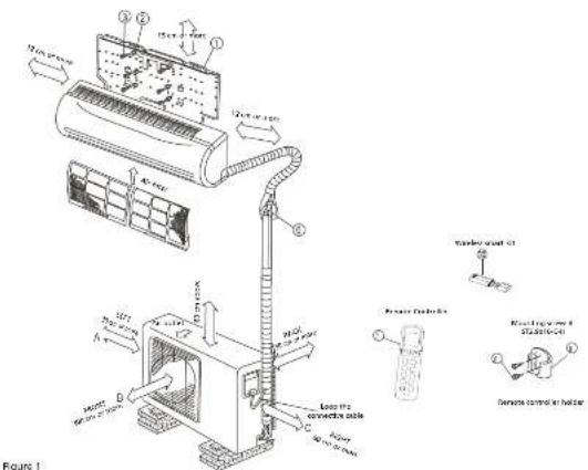
This illustration is for explanation and indication purposes only. The illustration may be different from the air conditioner you purchased.
3. ACTIVITIES FOR INSTALLING THE AIR CONDITIONER FOR THE SC41XX & SC5XXX MODELS
a. Decide where to position the indoor and outdoor unit. See chapter 5 and 6.

CAUTION
- Keep in mind where the condensation can be drained off to.
- The distance between indoor and outdoor unit can be max. 4 m (the length of the piping).
b. Fit the Installation Plate for the indoor unit. See chapter 7.1
c. Drill a hole to outside that the piping can be fed through. See chapter 7.2.
d. Feed the piping from the interior unit through the hole in the wall and hang the interior unit, using the hooks on the back, to the topmost hooks on the installation plate and confirm that the unit is properly attached. Do not click the bottom hooks in yet.

The piping package, coupled to the interior unit, is heavy. Never let the piping package hang freely from the interior unit. Support the whole piping package during installation of the interior unit. The weight of the piping package can cause the piping on the interior unit to bend and even break. Damage to the piping on the interior unit is caused by unprofessional installation and are not covered by the guarantee.
GB
46
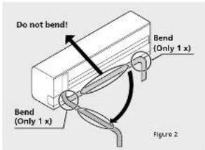
Bending the refrigerant piping at the back of the unit needs to be done with the highest care! The piping consists of copper. When bending the highlighted part more than 1 time the Copper will start cracking due to a physical process. Cracking can cause leakage refrigerant leakage and is not covered by the warranty. See picture 2.
e. Feed the condensation hose through the hole in the wall and connect it to the hose which is installed on the interior unit. See chapter 9.1.

TIP
The condensation hose can be more easily attached by pulling the bottom of the interior unit about 5 cm from the wall and putting something temporarily between it and the wall so that the gap remains open. See figure 3.
- Now click the bottom hooks to of the interior unit to the mounting plate.
g. Position the exterior unit see chapter 5.2
h. Connect the quick connector coupling with the coupling on the exterior unit. Then connect the power cable with the earth wire to the interior and exterior unit. See chapter 8.
i. Check the air conditioner for any cooler liquid leakage. See chapter 13.
j. Check that the air conditioner is properly installed.
k. Connect the plug of the power supply cable to the power supply and check that the air conditioner is working properly. See chapter 11.1.
4. ACTIVITIES FOR INSTALLING THE AIR CONDITIONER FOR THE S41XX AND S5XXX MODELS
a. Determine the location where the interior unit and exterior unit can be installed. See chapter 5 and 6.
b. Mount the mounting plate of the interior unit. See chapter 7.1.
c. Drill a hole to outside that the lines can be fed through. See chapter 7.2.
d. Hang the interior unit, by the hooks on the back, on the top hooks of the mounting plate and check that it is securely mounted. Do not click the bottom hooks in yet.

CAUTION
if the piping is exiting the unit behind on the right then the piping must be fed through the drilled hole at the same time as hanging the interior unit.
e. Feed the piping, the power cable and the condensation hose through the hole in the wall.
GB
47

TIP
The piping, power cable and condensation hose can be attached easier
by pulling the bottom of the interior unit about 5 cm from the wall and temporarily inserting something so that the gap stays open, see figure 3.
- Connect the coolant pipes, the power cables and the condensation hose to the interior unit. See chapter 8.2, 9, 10 and 11.2.
g. Position the exterior unit see chapter 5.2
h. Connect the piping and the power cable to the exterior unit. See chapter 11.2.
i. Vacuum the cooling unit. See chapter 12.
J. Check the cooling circuit for leakages. See chapter 13.
k. Check that the entire system is properly installed. - Connect the plug of the power supply cable to the power supply and check that the air conditioner is working properly. See chapter 15.
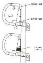
Figure 3
5. DETERMINING THE LOCATION OF THE INSIDE AND OUTSIDE UNIT.
5.1 Determining the location of the inside and outside unit for the S41xx, S5xxx, SC41xx & SC5xxx models.
- Do not expose the indoor unit to heat or steam.
- Select a place where there are no obstacles in front or around the unit.
- Make sure that condensation drainage can be conveniently routed away continuously going downwards.
- Do not install near a doorway.
- Ensure that the space on the left and right of the unit is more than 12cm.
- Use a wire detector to detect wires and/or electric cables, to locate studs to prevent unnecessary damage to the wall.
- The top of the indoor unit should be installed on the wall at a height of 2.3 metres or more from the floor.
- The indoor unit should be installed allowing a minimum clearance of 15cm from the ceiling.
- Be sure to level the indoor unit.
- When determining the location of the interior unit take the possible locations of the exterior unit into account. Interior and exterior part must be linked by piping and cables.

TAKE CARE
For the SC41xx & SC5xxx models: The length of the piping is 4 metres.
For the S41xx & S5xxx models: For units with a capacity of up to 6.0 kW, the maximum pipe length between the inside and the outside part is 20 metres. For units with a capacity > 6.0 kW, the maximum pipe length between the inside and the outside part is 30 metres. For units with a capacity of up to 6.0 kW, the maximum difference in height between the inside and the outside part is 8 metres. For units with a capacity > 6.0 kW, the maximum difference in height between the inside and the outside part is 20 metres.
5.2 Determining the location of the exterior unit for the S41xx, S5xxx, SC41xx & SC5xxx models
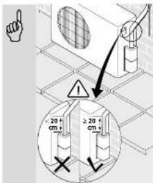
- Install the outdoor unit on a rigid base to prevent increasing noise level and vibration.

NOTE
The outdoor unit produces sound when in use, this could interfere with local legislation. It is the responsibility of the user to check and to make sure the equipment is in full compliance with local legislation.
- Determine the air outlet direction where the drainaged air is not blocked.
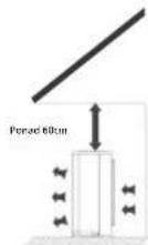
• Take the air conditioner weight into account. - If an awning is built over the outdoor unit to prevent direct sunlight or rain exposure, make sure that heat radiation from the condenser is not restricted.
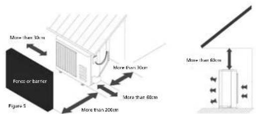
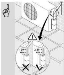
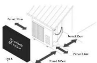
- Ensure that the clearance around the back of the unit is more than 30 cm and left side is more than 30 cm. The front of the unit should have more than 200 cm of clearance and the connection side (right side) should have more than 60 cm of clearance. See picture 5.
- Be sure to level the outdoor unit
GB
48
GB
49
- When determining the location of the exterior unit take into account the possible location of the interior unit. The interior and exterior units must be connected by pipes and cables.

TAKE CARE
For the SC41xx & SC5xxx models: The length of the piping is 4 metres.
For the S41xx & S5xxx models: For units with a capacity of up to 6.0 kW, the maximum pipe length between the inside and the outside part is 20 metres. For units with a capacity > 6.0 kW, the maximum pipe length between the inside and the outside part is 30 metres. For units with a capacity of up to 6.0 kW, the maximum difference in height between the inside and the outside part is 8 metres. For units with a capacity > 6.0 kW, the maximum difference in height between the inside and the outside part is 20 metres.
- Do not place animals and plants or other obstacles in the path of the air inlet or outlet.
• Always install the air conditioner at an easily accessible location. - Consult and follow local legislation regarding mounting and installation of air conditioner equipment.
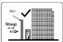
- In the case that the installation place is exposed to strong wind such as a seaside, make sure the fan is operating properly by putting the unit lengthwise along the wall or using a dust or shield plates. See picture 6.
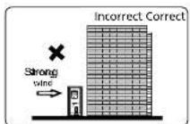
Figure 6
- If the exterior unit is installed on a roofing structure or exterior wall then it can result in bothersome noise and vibrations.
- Ensure that the exterior unit can be attached to a stable substructure.
GB
50

ATTENTION
If need suspending installation, the installation bracket should accord with all technical requirements. The installation wall should be strong enough or actions to reinforce should be taken. The connection between bracket and wall, bracket and the air conditioner should be firm, stable and reliable. In case of any doubts or uncertainty do not attempt to install the unit but have the support calculated and engineered by a skilled engineer.
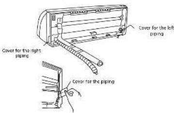
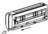
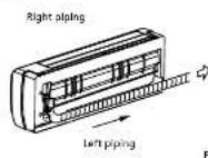
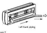
6. POSSIBILITIES FOR INSTALLING THE PIPING FROM THE INTERIOR UNIT TO THE EXTERIOR UNIT.
- The piping can be connected exiting from the left rear or right rear of the interior unit. Remove the left or right breakout plate. See figure 7.
- The piping can be connected exiting from the left rear or right rear. See figure 7.
GB
51
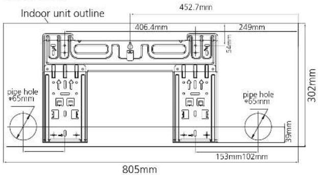
7. MOUNTING THE INSTALLATION PLATE AND MAKING THE PIPING FEEDTHROUGH.
7.1 Mounting the installation plate of the interior unit.

WARNING!
Use a pipe detector to detect electrical conduits and pipes in the wall before drilling the required holes to prevent unnecessary damage to the wall or dangerous situations.
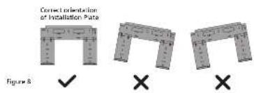
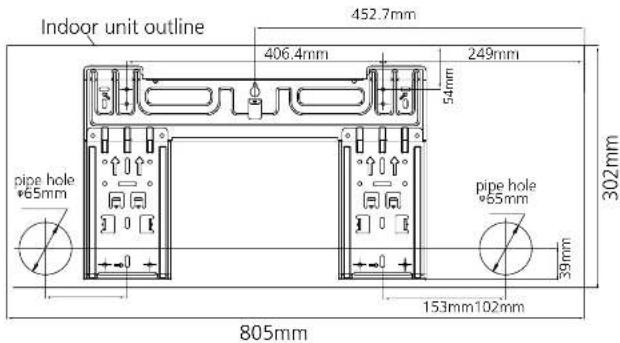
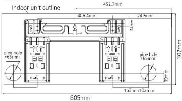
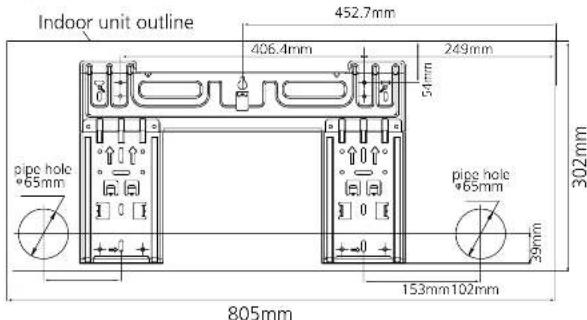
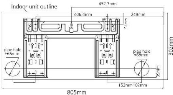
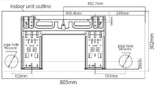
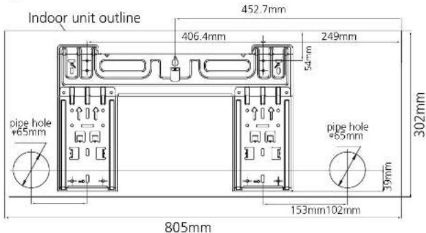
a. Fit the installation plate ① horizontally on structural parts of the wall with spaces around the installation plate. See figure 8.
b. If the wall is made of brick, concrete or the like, drill eight (8) 5mm diameter holes in the wall. Insert clip anchor ② for appropriate mounting screws ③.
c. Fit the installation plate (1) on the wall with eight (8) type "A" screws (3).

REMARK
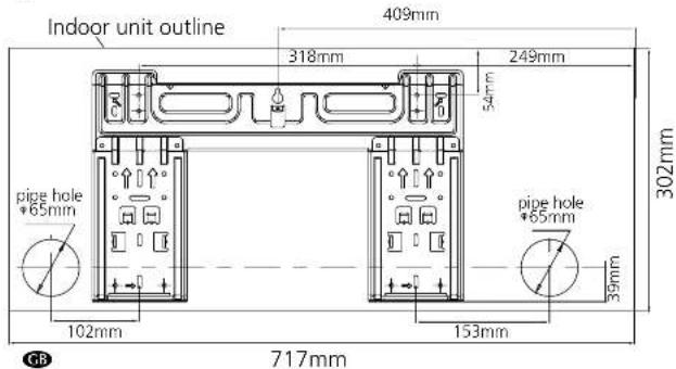
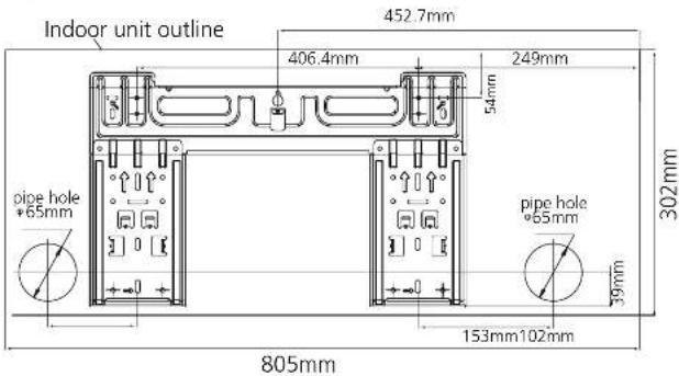
Mount the mounting plate and drill the holes in the wall corresponding to the material of the wall and the mounting points on the mounting plate in question (dimensions are in "mm" unless otherwise indicated).
S(C)5x25/SC4125
S(C)5x32/SC4132
5(C)5x48/SC4148

7.2 Drilling the piping, condensation hose and cable feed-through.
a. Determine the positions of the holes according to the diagram detailed in Fig. 9. Drill one (1) hole (≥ 85 mm for SC41xx & SC5xxx / ≥ 65 mm for S41xx & S5xxx) slanting slightly downwards to outdoor side, this will prevent water to come indoors (fig 10).
b. Always use wall hole conduit when drilling metal grid, metal plate or the like.
GB
52
53
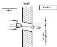
Figure 10
8. CONNECTING THE COOLANT PIPES
8.1 Connecting and disconnecting the coolant pipes for the SC41xx & SC5xxx models.

TAKE CARE
Connecting the coolant pipes of an air conditioner must be carried out in accordance with the applicable national regulations and laws. Connecting the coolant pipes may only be carried out by an authorised fitter.

TAKE CARE
The piping package, coupled to the interior unit, is heavy. Never let the piping package hang freely from the interior unit. Support the whole piping package during installation of the interior unit. The weight of the piping package can cause the piping on the interior unit to bend and even break. Damage to the piping on the interior unit due to unprofessional installation and is not covered by the guarantee.

TAKE CARE
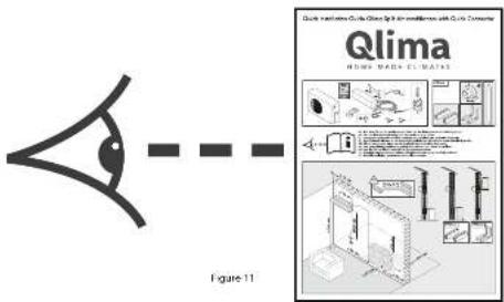
For your safety, always wear safety eye wear and work gloves when connecting the pipes. The piping is coupled the interior unit at the factory. Read through the "quick installation guide" to understand how the piping and power cable must be connected to the exterior unit.
GB
54

The last 20 cm of the refrigerant pipe, close to the connector must be kept straight. Bending can cause leakage and is not covered by the warranty.
Figure 12

ATTENTION
All refrigerant work and refrigerant piping should comply with the local legislation, standards and codes and should only be done by qualified and skilled people.
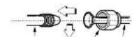
To disconnect the couplings:
Step 1: Shut down the A/C unit and unplug the electrical power cord from the wall outlet.
Step 2: Wait five minutes for the line pressure between the indoor compressor unit and outdoor condensing unit to equalize.
Step 3: Pull the male coupling handle up and toward the male coupling to the full back position.
Step 4: Retract the Release Sleeve on the female coupling to release the male coupling half from the female half.
Step 5: To seal and protect from dust, reinstall the protective cap and plug.
8.2 Connecting the coolant pipes for the S41xx & S5xxx models
a. Fit a gland nut or suchlike to the piping and make a so-called "flare" at the end of the piping.
b. Interior unit; Tighten the gland nut by hand to the piping on the interior unit and then tighten it with a spanner and torque wrench as shown in fig. 13.
c. Exterior unit: Tighten the gland nut by hand to the connections on the valves on the exterior unit and then tighten it with a spanner and torque wrench as shown in fig. 13.
Indoor unit tubing
Piprgs
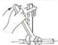
Figure 13
d. Select the correct tightening torque (shown table 1) in order to prevent the pipes, connecting pieces and nuts from being damaged.
GB
55
| Outer diam. | Tightening torque (N.cm) | Additional tightening torque (N.cm) |
| ∅ 6.35 | 1500(153kgf.cm) | 1600(163kgf.cm) |
| ∅ 9.53 | 2500(255kgf.cm) | 2600(265kgf.cm) |
| ∅ 12.7 | 3500(357kgf.cm). | 3600(367kgf.cm) |
| ∅ 16.0 | 4500(459kgf.cm). | 4700(479kgf.cm) |
e. Insulate the connection points on the interior section with insulation material to prevent condensation build-up.
1. Wind the piping, connection cable and drain hose, behind the interior unit, with tape so that a firm bundle is formed. This makes it easier to mount the interior unit to the mounting plate.

ATTENTION
Copper lines must be insulated independently from each other.

ATTENTION
Always use the highest care when bending the piping. Make sure that the piping always is bent and not buckled. In case of a buckled pipe: replace the complete piping or the buckled part, as this is a potential refrigerant leak and may cause damage to the air conditioner.
9. CONNECTION THE CONDENSATION DRAINAGE HOSE FOR THE S41XX & S5XXX, SC41XX, SC5XXX MODELS
9.1 Connection the condensation discharge hose to the interior unit.
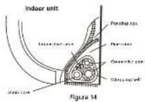
Connect the included condensation drainage hose to the interior unit by sliding the hose over the hose nipple on the interior unit. Ensure that the condensation drainage hose always runs downwards and do not hang the end in the water. See fig. 15.
Always run the condensation drainage hose under the coolant pipes to prevent that the condensation tray from overflowing.
GB
56

CAUTION
- Be sure that the drain hose is located at the lowest side of the bundle. Locating at the upper side can cause drain pan to overflow inside the unit.
- Run the drain hose sloped downward over the whole length to drain out the condensed water smoothly.
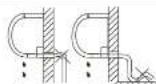
Do not block water flow by a rise.

Do not cut the end of drain how into water.
Figure 15
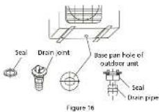
9.2 Drain joint installation
Fit the seal into the drain elbow, then insert the drain joint into the base pan hole in the bottom of the outdoor unit, rotate 90° to assemble them securely. Connect the drain joint with an extension drain hose (not included). In this way condensed water, which is produced during heating mode of the air conditioner, can be drained away. See fig. 16.
10. ELECTRICAL WORK
- Connect the air conditioner to a separate group. Ensure that this group has the correct fuse
- See following table.
- Power voltage supplied should be in the range of 95%\~105% of rated voltage on rating table.
• The power supply must have an earth leak switch installed. - Ensure the air conditioner is grounded well.
- Connect the wires according to the attached electrical connection diagram located on the panel of the outdoor unit. See chapter 11
- All wiring must comply with local and national electrical standards and codes and be installed by qualified and skilled people.
| Model Power supply | Input Rated Current (Switch/Fuse) | Power cord size |
| ≤ 3,5 kW 230V~50Hz 16A 2,5 mm | ^2 | |
| >3,5 kW 230V~50Hz 16A slow 2,5 mm | ^4 |

NOTE!
The supply voltage should be consistent with the rated voltage of the air conditioner.
GB
57
11. CONNECTING THE ELECTRICAL CABLES.
11.1 Connecting the electrical cables for the SC41xx & SC5xxx models.
a. 4,5 Meter cable for electrical connection between indoor and outdoor unit is delivered with the package and is included in the refrigerant piping sleeve (indoor unit).
B. The electrical cable is provided with an electrical quick connector.
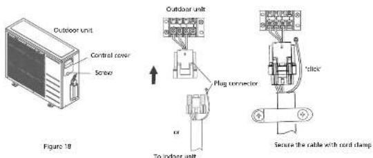
c. The outdoor unit is also provided with electrical quick connector.
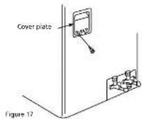
d. Remove the control cover from the outdoor unit by loosening the screw.
e. Click the connector of the interior unit into the connector of the exterior unit and secure the cable to the terminal block with the cable clamp mounted on it.
1. The earth cable must be connected directly to the metal plate on which the terminal strip is mounted. The location is indicated with the symbol
g. Only connect the power supply cable once the entire installation of the air conditioner has been completed.

TAKE CARE
For models with a capacity < 4.5 kW plug the plug into a wall socket.
For models with a capacity > 4.5 kW connect the power supply cable directly the power source.
Do not use a plug and socket as the high current can damage both the terminals of the plug and the socket and even cause a fire.
11.2 Connecting the electrical cables for the S41xx & S5xxx models.
a. Connect the cable to the indoor unit
GB
58
b. Indoor/Outdoor connection cable should be H07RN-F type, 2.5 mm².
c. To mount the cable to the interior unit: Remove the front panel and the cover plate of the terminal strip on the right hand side of the interior unit. Figure 19.
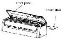
Figure 19
d. The cable can be fed through from the back of the interior unit to the terminal strip.
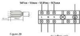
e. Connect the electrical wires to the terminal strip, for the correct location see fig 20.
f. Attach the cable of the indoor unit. Remove the cover plate of the terminal strip of the outdoor unit.
g. Connect the connection cable to the terminal strip (zie picture 21). Attach the cables so that the position of the wires matches the connection of the cables to the indoor unit (the letters L N S, the earth cable and, for the models with a capacity > 6.0 kW, the numbers 1 + 2).
h. The earth cable must be connected directly to the metal plate on which the terminal strip is mounted.
The location is indicated with the symbol
i. In models with a capacity of up to 6.0 kW, the supply cable is already preassembled on the inside part. In models with a capacity > 6.0 kW, the supply cable must be connected to the outside part (the supply cable is not included).
j. Only connect the power supply cable once the entire installation of the air conditioner has been completed.

TAKE CARE
For models with a capacity < 4.5 kW plug the plug into a wall socket.
For models with a capacity >4.5 kW connect the power supply cable directly the power source. Do not use a plug and socket as the high current can damage both the terminals of the plug and the socket and even cause a fire.
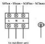

Figure 21
GB
59
12. EVACUATING THE COOLING SYSTEM OF THE S41XX & S5XXX MODELS
Air and moisture that remain in the refrigerant system, e.g. after installation, can cause undesirable effects
or damage as indicated below:
• Pressure in the system rises.
- Operating current rises.
• Cooling or heating efficiency drops.
- Moisture in the refrigerant circuit may freeze and block capillary tubing.
• Water may lead to corrosion of parts in the refrigeration system.
• Damage of the compressor.
Therefore, the indoor unit and tubing between the indoor and outdoor unit must always be leak tested and evacuated with aid of a vacuum pump to remove any noncondensables and moisture from the system.

TAKE CARE
Evacuating the coolant piping and the interior unit of the air conditioner must in accordance with the applicable national regulations and laws. Evacuating the coolant piping and the interior unit may only be carried out by a certified air conditioner fitter.
13. CHECK FOR COOLANT LEAKAGE FOR THE S41XX, S5XXX, SC41XX & SC5XXX MODELS

TAKE CARE
Evacuating the coolant piping and the interior unit of the air conditioner must be carried out in accordance with the applicable national regulations. The test for coolant leakage of the coolant piping and the interior unit may only be carried out by a certified fitter.
POSSIBILITIES FOR LEAK CHECK AIR CONDITIONER
- Soap water method: Apply a soap water or a liquid neutral detergent on the indoor unit connection or outdoor unit connections by a soft brush to check for leakage of the connecting points of the piping. If bubbles come out, the pipes have leakage.
• Dedicated special leak detector: Use the leak detector to check for leakage.
14. TOPPING UP COOLANT FOR PIPING LENGTHS ABOVE 05 METRES.

TAKE CARE
Connecting the coolant pipes of an air conditioner must be carried out in accordance with the applicable national regulations and laws. Refilling the coolant may only be carried out by an authorised fitter.
The air conditioner is filled with sufficient coolant at the factory for a pipe length of a maximum of 5 metres.
If the coolant piping is longer than 5 metres then the air conditioner must be topped up with extra coolant.
The amount of coolant to be added is shown in table 2
| Model | For piping longer than 5 metresExtra filling per meter in grams |
| 2.5 – 2.6 kW 20 | |
| 3.1 – 3.6 kW 20 | |
| 4.8 – 5.4 kW 20 |
Tabel 2
Only use coolant of the same type as stated on the type plate.
15. TEST RUNNING AFTER INSTALLATION
Perform test running after completing electrical safety check and gas leak check.
The test running time should last more than 30 minutes.
Check if all the functions works well during test running. Especially check whether the drainage of indoor unit is smooth or not.
GB
60
GB
61

ATTENZIONE
5(C)5x32/SC4132
5(C)5x48/SC4148
1
74

NL
92
5(C)5x32/SC4132

5(C)5x48/SC4148
NL
94
Rys. 1

UWAGA
5(C)5x32/SC4132
PL
112
PL
113
5(C)5x48/SC4148

ATENÇÃO
5(C)5x32/SC4132
S(C)5x48/SC4148


5(C)5x48/SC4148

7.2 Vrtanje prehoda za cevi, cev za kondenzat in kabel
Distributed in Europe by PVG Holding B.V.
Benötigen Sie weitere Informationen oder treten Probleme auf, besuchen Sie bitte unsere Website www.qlima.com, oder setzen Sie sich mit unserem Kundendienst in Verbindung (Telefonnummer auf www.qlima.com).
For alle yderligere oplysninger eller ved eventuelle problemer med apparatet henvises til www.qlima.com eller det lokale Kundecenter (telefonnumre findes i www.qlima.com).
ES Si necesita información o si tiene algún problema, visite nuestra página Web www.qlima.com, o póngase en contacto con el servicio cliente (hallará el número de teléfono en www.qlima.com).
F Si vous souhaitez obtenir des informations supplémentaires ou si vous rencontrez un problème, rendez-vous sur notre site Web (www.qlima.com) ou contactez notre service client (vous trouverez l'adresse et numéro de téléphone sur www.qlima.com).
FHN Jos haluat huoltoapua, lisätietoja tai laitteen kanssa tulee ongelmia, tutustu verkkosivustoon osoitteessa www.qlima.com tai kysy neuvoa PVG kuluttajapalvelukeskuksesta (www.qlima.com).
(6) If you need information or if you have a problem, please visit the our website (www.qlima.com) or contact our sales support (you find its phone number on www.qlima.com)
① Per informazioni e in caso di problemi, visitate il sito Web www.qlima.com oppure contattate il Centro Assistenza Clienti (per conoscere il numero di telefono, consultate www.qlima.com).
Hvis du trenger informasjon, eller hvis du har et problem med produktet, kan du gå til nettsidene www.qlima.com. Alternativt kan du kontakte med PVG' forbrukertjeneste (telefonnummeret i www.qlima.com).
Als u informatie nodig hebt of als u een probleem hebt, bezoek dan de onze website (www.qlima.com) of neem contact op met de afdeling sales support (adres en telefoon op www.qlima.com).
Se necessitar de informações ou se tiver problemas, visite o Web site www.qlima.com ou contacte o Centro de Assistência (número de telefone o www.qlima.com)
FL W przypadku problemów i w celu uzyskania szczegółowych informacji odwiedź stronę internetową Qlima dostępną pod adresem www.qlima.com lub skontaktuj się z Centrum kontaktów Qlima (www.qlima.com)
Om du behöver service eller information eller har problem med apparaten kan du besöka www.qlima.com eller kontakta Qlima kundtjänst (du hittar telefonnumret på www.qlima.com).
Slo Če želite dodatne informacije, obiščite spletno mesto podjetja na naslovu www.qlima.com ali pokličite na telefonsko (www.qlima.com).
TR Daha fazla bilgiye ihtiyaç duyarsanız veya bir sorunla karşılaşırsanız, www.qlima.com adresindeki Qlima Internet sitesini ziyaret edin veya ülkenizde bulunan Qlima müşteri merkeziyle iletişim kurun (telefon numarasını: www.qlima.com).