— Controller — Mode d'emploi PDF")
TX Racing Wheel Leather Edition (Xbox One) - Controller THRUSTMASTER - Free user manual and instructions
Find the device manual for free TX Racing Wheel Leather Edition (Xbox One) THRUSTMASTER in PDF.

| Product Type | Force Feedback Racing Wheel |
| Brand | Thrustmaster |
| Model | TX Racing Wheel Leather Edition |
| Compatible Platforms | Xbox One, PC |
| Power Supply | Internal 220-240V or 100-125V depending on version, or external 110-240V |
| Weight | 7 kg (approx.) |
| Rim Material | Leather |
| Rotation Angle | 900° (auto-calibration) |
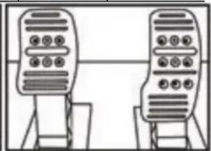
| Pedal Set Included | Yes, 3 pedals (accelerator, brake, clutch) adjustable in height, spacing and tilt |
| Sequential Paddles | Yes, 2 levers (up/down) |
| Mounting System | Clamp mounting on table/desk or M6 screws for cockpit |
| Connections | USB for console/PC, pedal connector, shifter connector (optional) |
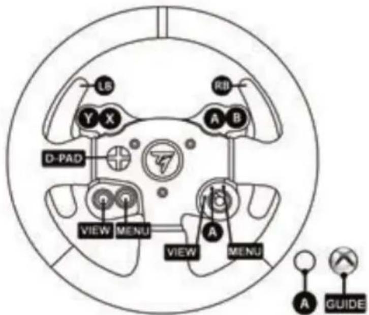
| Additional Buttons | Multidirectional D-pad, 3-position switch, MODE button, Xbox Guide button |
| Firmware Update | Via PC on Thrustmaster website |
| Operating Temperature | Internal temperature sensor; automatic shut-off in case of overheating |
| Maintenance | Clean with a dry cloth; avoid dust and humidity |
| Safety | Do not use barefoot; avoid pinching; do not expose to water |
| Warranty | 2 years in EU (according to local legislation) |
| Optional Accessories | TH8A Shifter (sold separately) |
| Repairability | No user-serviceable parts; contact technical support |
Frequently Asked Questions - TX Racing Wheel Leather Edition (Xbox One) THRUSTMASTER
User questions about TX Racing Wheel Leather Edition (Xbox One) THRUSTMASTER
0 question about this device. Answer the ones you know or ask your own.
Ask a new question about this device
Download the instructions for your Controller in PDF format for free! Find your manual TX Racing Wheel Leather Edition (Xbox One) - THRUSTMASTER and take your electronic device back in hand. On this page are published all the documents necessary for the use of your device. TX Racing Wheel Leather Edition (Xbox One) by THRUSTMASTER.
USER MANUAL TX Racing Wheel Leather Edition (Xbox One) THRUSTMASTER
natural_image
Abstract black and white geometric shape with diagonal lines (no text or symbols)TX RACING WHEEL LEATHER EDITION
TX RACING WHEEL LEATHER EDITION
FOR XBOX ONE
User Manual
natural_image
Technical line drawing of a steering wheel and three motor stators on a platform (no text or symbols)WARNING:
To ensure that your TX Racing Wheel functions correctly with games for XBOX ONE,
you may be required to install the games' automatic updates
(available when your games console is connected to the Internet).
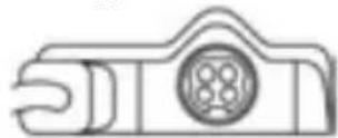
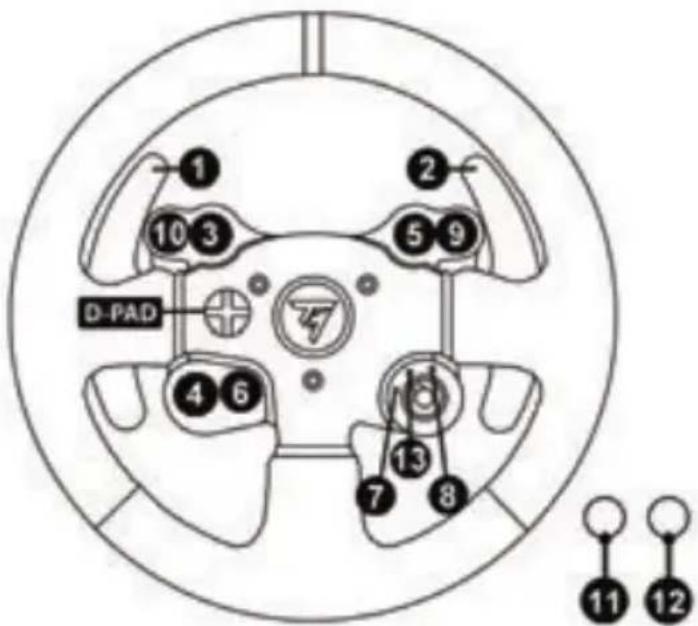
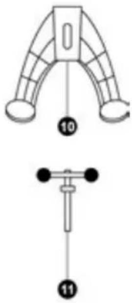
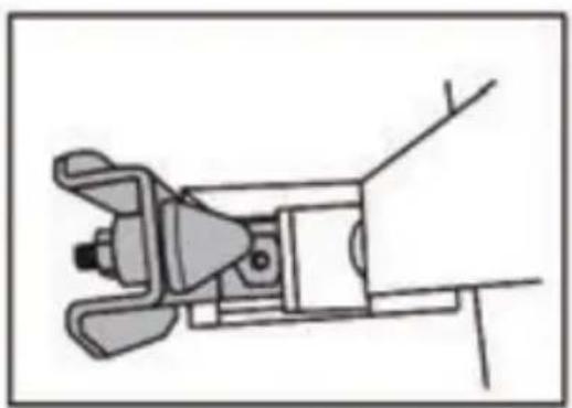
TECHNICAL SPECIFICATIONS
1 Racing wheel base
2 Racing wheel
3 2 sequential gear shift levers (Up & Down)
4 Multidirectional D-Pad
5 Switch (3 positions)
6 MODE button + Red/Green indicator light
7 Xbox Guide button
8 White indicator light
9 Large threaded hole (for attachment system and tightening screw)
10 Attachment system
11 Metal fastening screw
12 Thrustmaster Quick Release
13 Controller pairing (for Kinect™ detection)
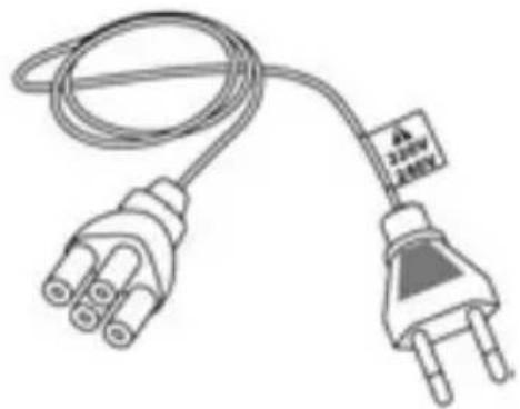
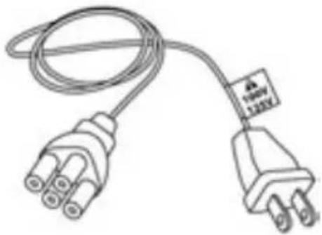
14 Mains supply connector (type A or B) (Varies from one country to another)
15 Racing wheel USB cable and connector
16 Gearbox connector
(sold separately, forthcoming release)
17 Pedal set connector
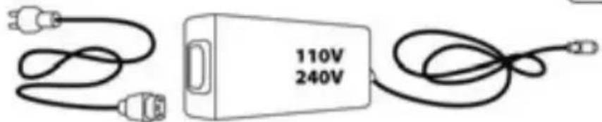
CONNECTING THE RACING WHEEL TO THE MAINS = PLEASE READ BEFORE PROCEEDING!
Your racing wheel's power supply varies according to the country where you purchased your device. The mains supply can be:
Internal, with:
* A power supply unit located directly inside the racing wheel's base, with a type A connector
*A 220-240V mains power supply cable
= compatible only with a 220-240V electrical supply.
natural_image
Line drawing of a three-pin electrical plug with a cable and terminal block (no text or symbols)
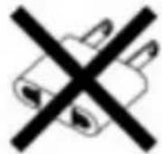
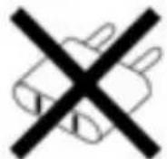
Never connect the 220-240V cable
to a 100-130V power outlet!
Never connect this cable to a mains power adapter!
Internal, with:
* A power supply unit located directly inside the racing wheel's base, with a type A connector
*A 100-125V power supply cable
= compatible only with a 100-125V electrical supply.
natural_image
Line drawing of an electrical plug with three leads and a terminal label (no text or symbols on the plug itself)
Never connect the 100-125V cable
to a 220-240V power outlet!
Never connect this cable to a mains power adapter!
IMPORTANT: if you do not know which voltage is supplied in the area in which you are using your racing wheel, please refer to your local electricity supplier.
External, with:
* An external power supply unit located on the racing wheel's base, with a type B connector
* A mains power supply cable
= compatible with all supply voltages, 110-240V.
WARNINGS
Before you use this product, please read this documentation carefully and keep it safe should you need to consult it later.

Warning – Electric shock
* Store the product in a dry location and do not expose it to dust or sunlight.
* Respect the connection direction.
* Do not twist or pull the connectors and cables.
* Do not spill any liquid on the product or its connectors.
* Do not short-circuit the product.
* Never dismantle the product; do not throw it onto a fire and do not expose it to high temperatures.
* Do not use a power supply cable other than the one provided with your racing wheel.
* Do not use the mains power supply cable if the cable or the connectors are damaged, split or broken.
* Make sure that the mains power cable is properly inserted into the power outlet and the connector located on the rear face of the racing wheel's base.
* Do not open. No user replaceable parts inside. Refer servicing to manufacturer, specified agency or qualified technician.
* Only use attachments/accessories specified by the manufacturer.
* If the steering wheel is operating unusually (if it is emitting any abnormal sounds, heat or odors), stop using it immediately, disconnect the power cable from the socket and disconnect the other cables.
* If you are not going to be using the steering wheel for an extended period, disconnect the mains adaptor from the wall socket.

Air vents
Make sure that you do not block any of the air vents on the steering wheel base. For optimum ventilation, respect the points below:
* Position the base at least 10 cm away from any wall surfaces.
* Do not place the base in any tight spaces.
* Do not cover the base.
* Do not let any dust build up on the air vents.

For safety reasons, never use the pedal set with bare feet or while wearing only socks on your feet.
THRUSTMASTER® DISCLAIMS ALL RESPONSIBILITY IN THE EVENT OF INJURY RESULTING FROM USE OF THE PEDAL SET WITHOUT SHOES.

Warning – Injuries due to force feedback and repeated movements
Playing with a force-feedback steering wheel may cause muscle or joint pain. To avoid any problems:
* Avoid lengthy gaming periods.
* Take 10 to 15 minute breaks after each hour of play.
* If you feel any fatigue or pain in your hands, wrists, arms, feet or legs, stop playing and rest for a few hours before you start playing again.

Warning – Injuries due to force feedback and repeated movements (suite)
* If the symptoms or pain indicated above persist when you start playing again, stop playing and consult your doctor.
* Keep out of children's reach.
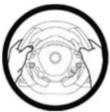
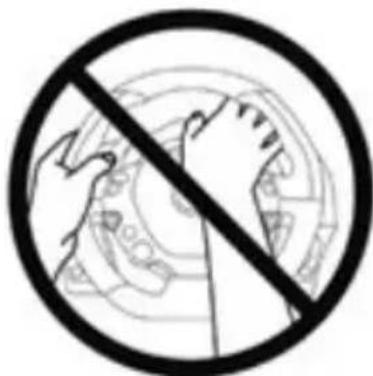
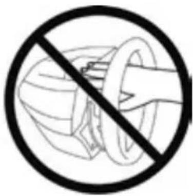
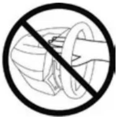
* During games, always leave both hands correctly positioned on the steering wheel without completely letting go.
* During gameplay, never place your hands or your fingers under the pedals or anywhere near the pedal set.
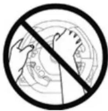
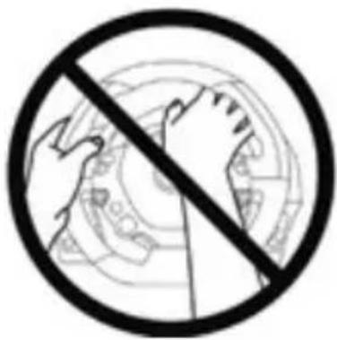
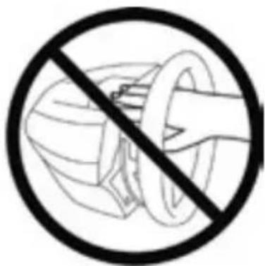
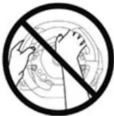
* During calibration and gameplay, never place your hand or your arm through the openings in the racing wheel.
* Check the steering wheel base is carefully clamped as per manual's instructions.
HEAVY PRODUCT

To be handled only by users 16 years of age or older

Be careful not to drop the product on yourself or on anyone else!
ALWAYS NEVER NEVER
natural_image
Symmetrical mechanical or architectural diagram with concentric circles and radial elements, enclosed in a black circular border (no text or symbols)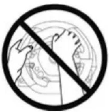
natural_image
Prohibition sign with a hand holding a globe, no text or symbols present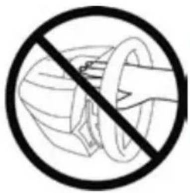
natural_image
Prohibition sign showing a hand holding a ring above a stylized object, enclosed in a circle (no text or symbols)
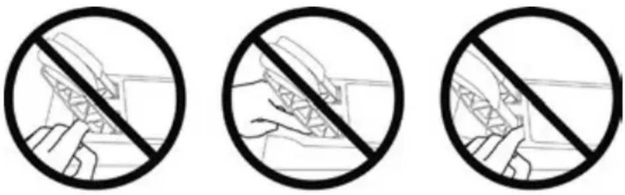
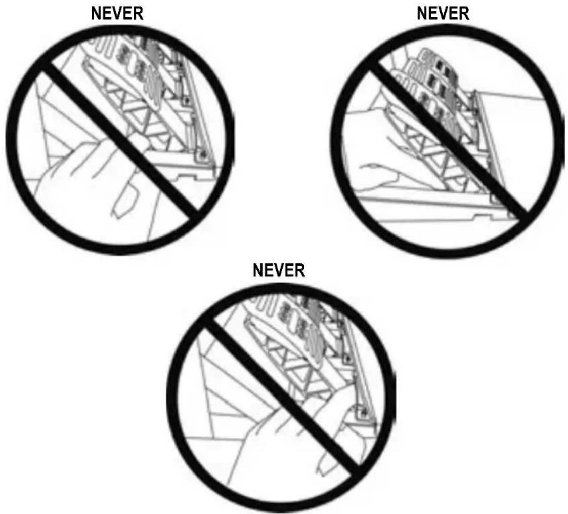
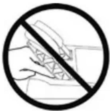
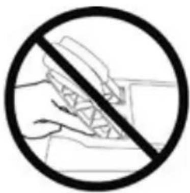
Warning – Pedal set pinch hazard when playing
* Keep the pedal set out of children's reach.
* When playing, never place your fingers on or anywhere near the sides of the pedals.
* When playing, never leave your fingers on or anywhere near the pedals' rear base.
* When playing, never place your fingers on or anywhere near the pedals' front base.
NEVER NEVER NEVER

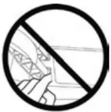
Warning – Pedal set pinch hazard when not playing
* Store the pedal set in a safe place, and keep it out of children's reach.
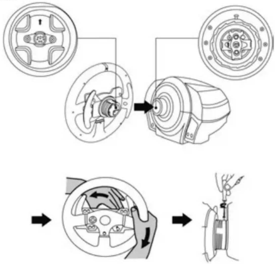
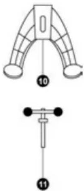
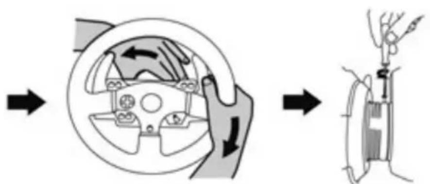
ATTACHING THE WHEEL TO ITS BASE
Align the connector locations using the arrows:
Base (1) connector: Arrow pointing upwards
Racing wheel (2) connector: Arrow pointing upwards
Once the connectors are correctly positioned, simply rotate the Thrustmaster Quick Release (12) device's ring counterclockwise, while holding the racing wheel (2) in position.
Then, tighten the ring as much as you can; to do so, hold the ring in position and rotate the racing wheel clockwise.
flowchart
graph TD
    A["Top Gear"] --> B["Left Gear"]
    B --> C["Central Gear Assembly"]
    C --> D["Right Gear Assembly"]
    D --> E["Final Assembly"]
Once you have installed the wheel, rotate it 180^ (when facing the wheel, the logo should be upside down) to access the small attachment screw located on the Thrustmaster Quick Release (12) device. Use a large cross-slot screwdriver to tighten the small attachment screw (do not use excessive force), turning it clockwise.

Do not use excessive force when screwing the small attachment screw (using a cross-slot screwdriver)!
Stop turning the screw as soon as you feel some resistance.
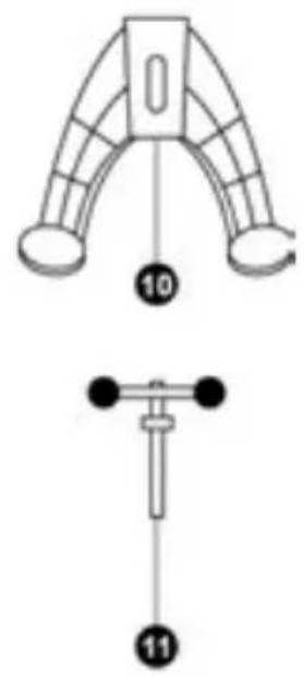
ATTACHING THE RACING WHEEL
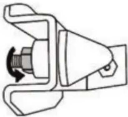
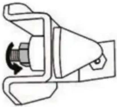
Attaching the racing wheel to a table or a desktop
- Place the racing wheel on a table or any other horizontal, flat and stable surface.
- Insert the fastening screw (11) in the attachment system (10), then tighten the device by turning the screw counterclockwise, so that it feeds into the large threaded hole (9) located beneath the racing wheel, until the device is perfectly stable.
ALWAYS NEVER
natural_image
Technical line drawing of a mechanical assembly with no visible text or symbols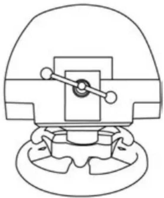
natural_image
Technical line drawing of a mechanical component with no visible text or symbolsWARNING: Never tighten the screw alone, without the attachment system!
(This could damage the racing wheel).
| ATTACHMENT / REMOVAL | DIRECTION | |
| To tighten:Turn the screw counterclockwise | 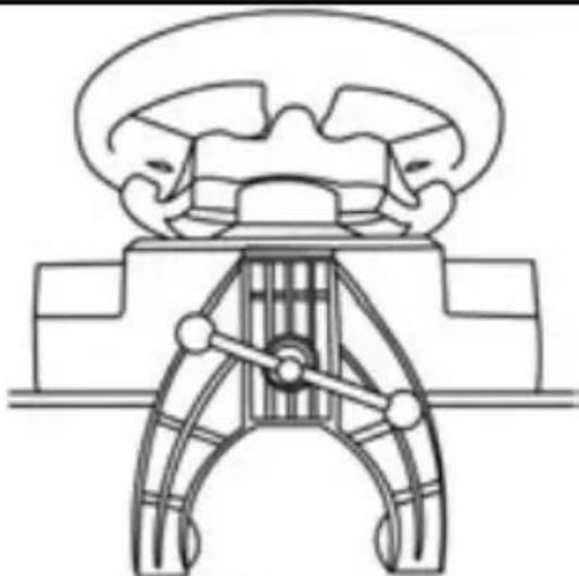 | |
 | ||
| To release:Turn the screw clockwise |  | |
Attaching the racing wheel's base to a cockpit
-
Place the racing wheel's base on the cockpit shelf.
-
Drive two M6 screws (not included) through the cockpit shelf, then feed them into the two small threaded holes located beneath the racing wheel.
Important: The length of the M6 screws should not exceed the thickness of the shelf + 12 mm; longer screws could cause damage to internal components located in the racing wheel's base.
- If required, tighten the standard attachment system by inserting the fastening screw in the large threaded hole.
XBOX ONE MAPPING
PC MAPPING
UPGRADING YOUR RACING WHEEL'S FIRMWARE
The firmware included in your racing wheel's base can be upgraded to a more recent version featuring product enhancements.
To display the firmware version that your racing wheel is currently running and upgrade it if required: on PC, connect to http://ts.thrustmaster.com. In the Updates and downloads section, click Xbox One / Wheels / TX Racing Wheel, then select Driver / Firmware and follow the instructions describing the download and setup procedure.
SETTING UP THE RACING WHEEL FOR THE XBOX ONE
- Connect the pedal set to the connector (17) located at the back of the racing wheel's base.
- Connect the power supply cable to the connector (14) located at the back of the racing wheel's base.
- Connect the power supply cable to a mains outlet with proper voltage specifications.
For more information about this, please refer to the CONNECTING THE RACING WHEEL TO THE MAINS section, on page 3 in this manual.
- Connect the racing wheel's USB connector (15) to one of the console's USB ports.
You are now ready to race!
AUTOMATIC RACING WHEEL AND PEDAL SET CALIBRATION
The racing wheel automatically self-calibrates when you connect the racing wheel to the mains and the racing wheel's USB connector to the console.
During this phase, the racing wheel will rotate quickly towards the left and the right, covering a 900 degree angle, before stopping at the center.

WARNING:
Never touch the racing wheel during the self-calibration phase! (This could cause an incorrect calibration and/or personal injuries).
AUTOMATIC CALIBRATION OF THE PEDAL SET
Never connect the pedal set to the racing wheel's base (or disconnect it from the base) when it is connected to the console or during gameplay (this could cause incorrect calibration).
Always connect the pedal set before connecting the racing wheel to the console.
Once the racing wheel's calibration is done and the game has been launched, the pedals are automatically calibrated after a few presses.

WARNING:
Never press the pedals during the racing wheel's self-calibration phase or while a game is loading! (This could cause incorrect calibration)
If your racing wheel and pedal set do not operate correctly, or if calibration seems incorrect: Turn off your console, disconnect your racing wheel entirely, reconnect all cables (using the mains power supply cable and pedal set), then restart your console and your game.
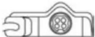
CONTROLLER PAIRING (13)
To ensure correct detection of your racing wheel, the device's controller pairing (located on the upper section of the racing wheel's base) must always remain in the KINECT™ camera's field of vision.
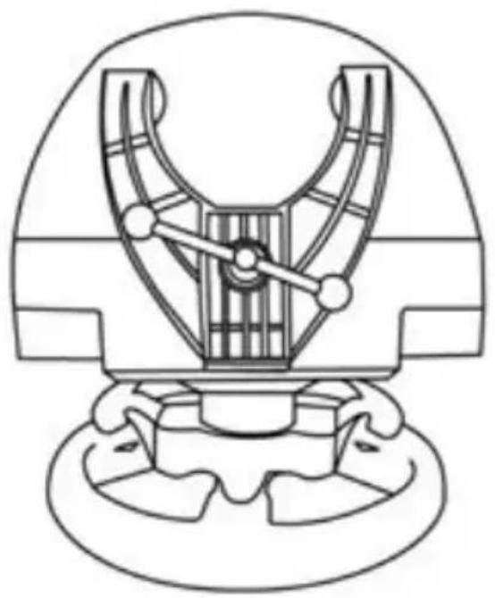
natural_image
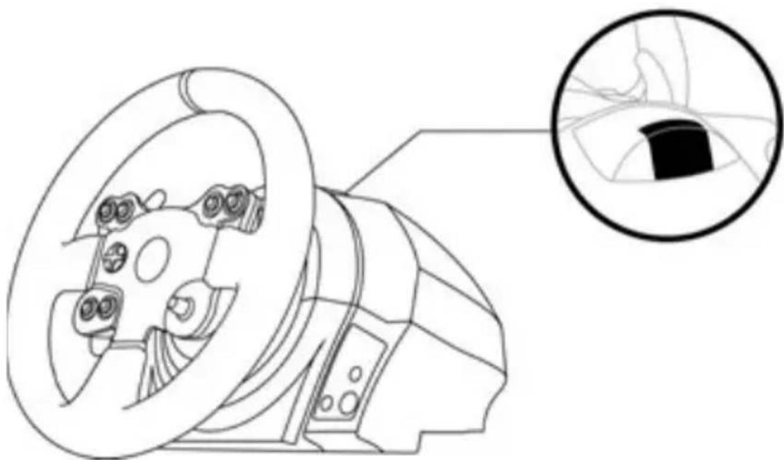
Technical line drawing of a mechanical component with an inset magnified view showing internal detail (no text or symbols)INTERNAL TEMPERATURE SENSOR
For safety reasons, the racing wheel's base features a temperature sensor. If the device's temperature becomes too high, your racing wheel can shut down suddenly. In this event:
- Unplug the mains power supply cable and the device's USB connector.
- Wait for the racing wheel's base to cool down entirely.
- Then, reconnect the device.
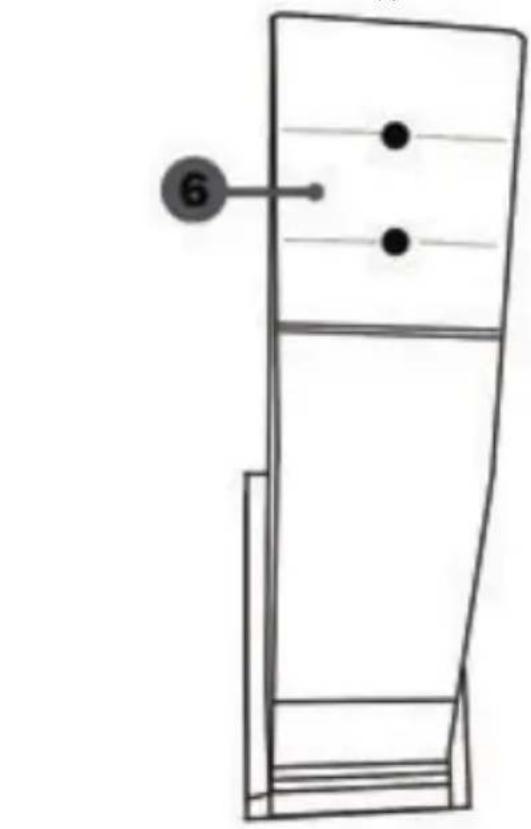
MODE BUTTON AND INDICATOR LIGHT (6)
MODE button for the pedal set
You can electronically swap the accelerator and clutch pedals.
To do so, simply press the MODE button (6) for 2 seconds.
The racing wheel's internal memory stores whether the pedals have been swapped around or not.
| ACCELERATOR AND CLUTCH PEDALS | Color of the MODE indicator light (6) |
| NORMAL | RED |
| SWAPPED AROUND | GREEN |
Other hints for the MODE button
To learn more about MODE button and indicator light, please visit http://ts.thrustmaster.com; in the Updates and downloads section, click Xbox One / Wheels / TX Racing Wheel, then select Manual / Help file.
HELP FILES AND FAQs (not stated in this manual)
Please access http://ts.thrustmaster.com; in the Updates and downloads section, click Xbox One / Wheels / TX Racing Wheel, then select Manual / Help file.
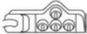
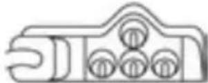
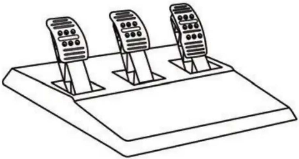
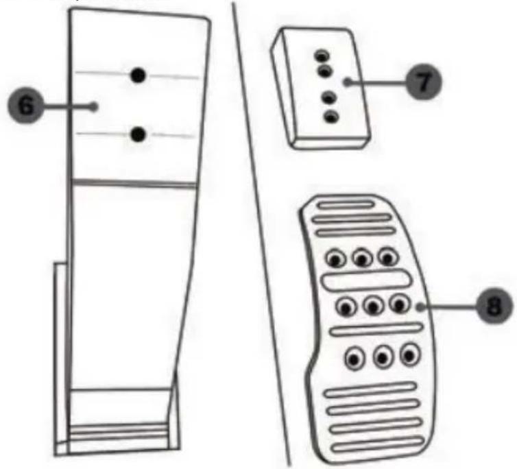
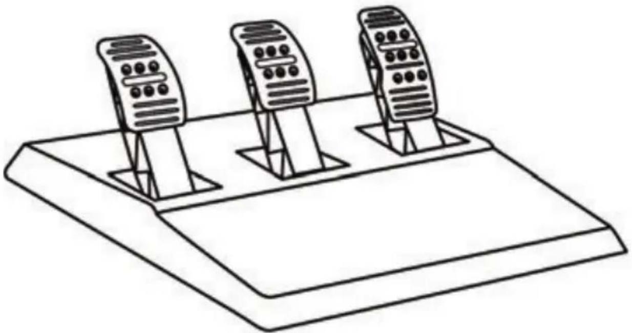
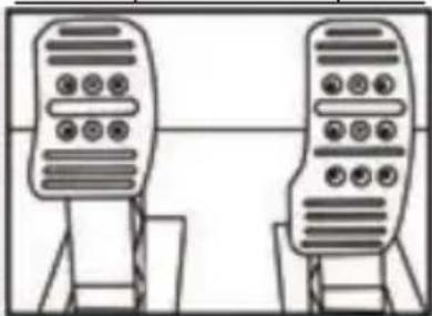
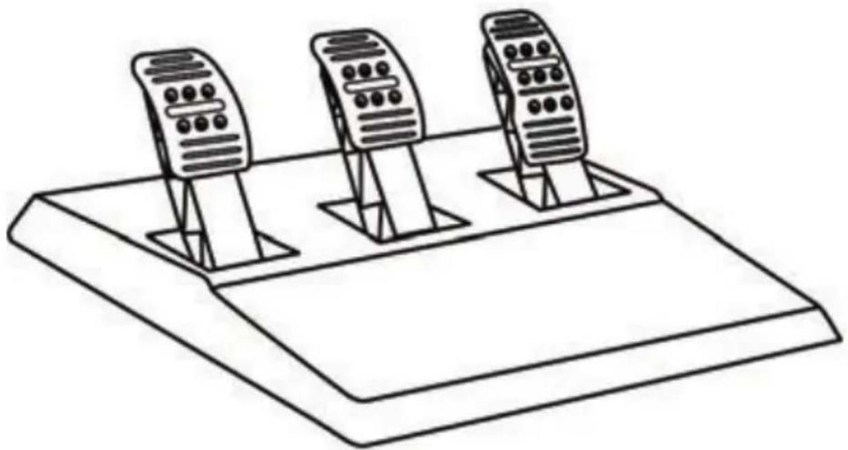
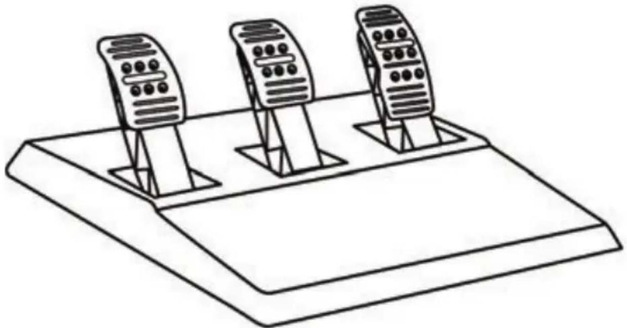
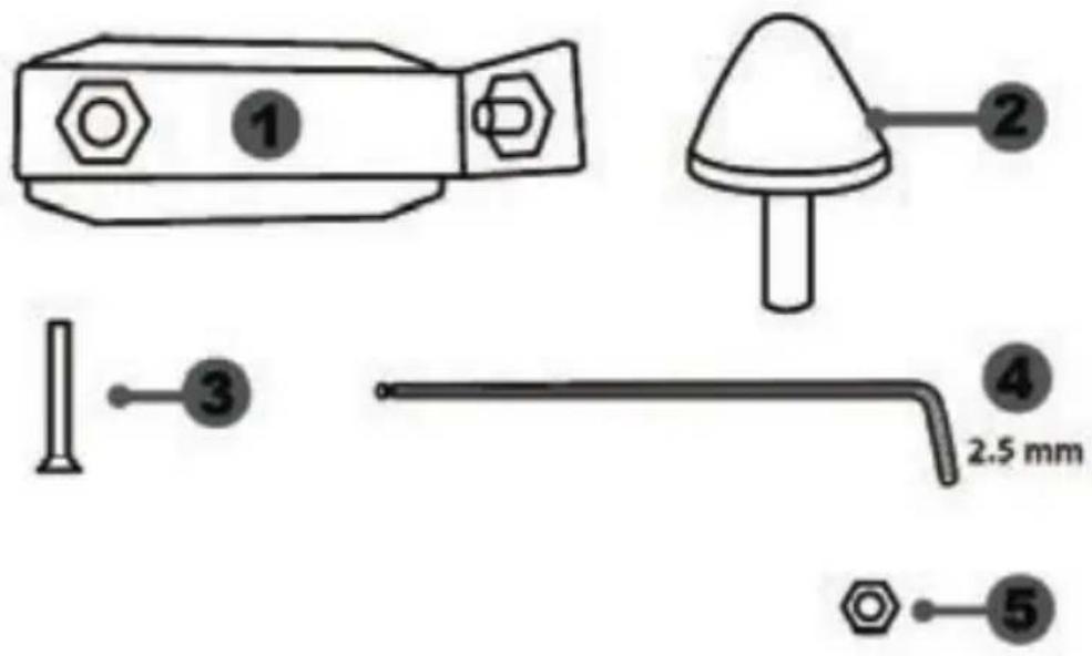
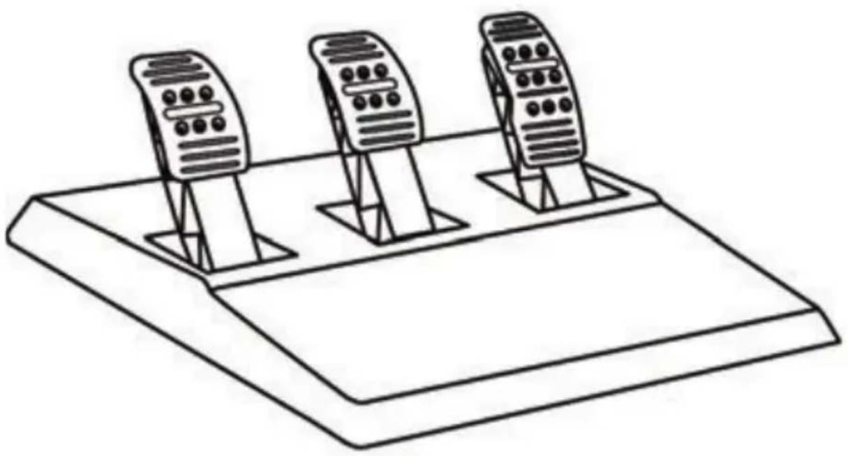
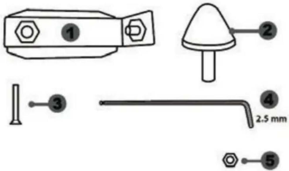
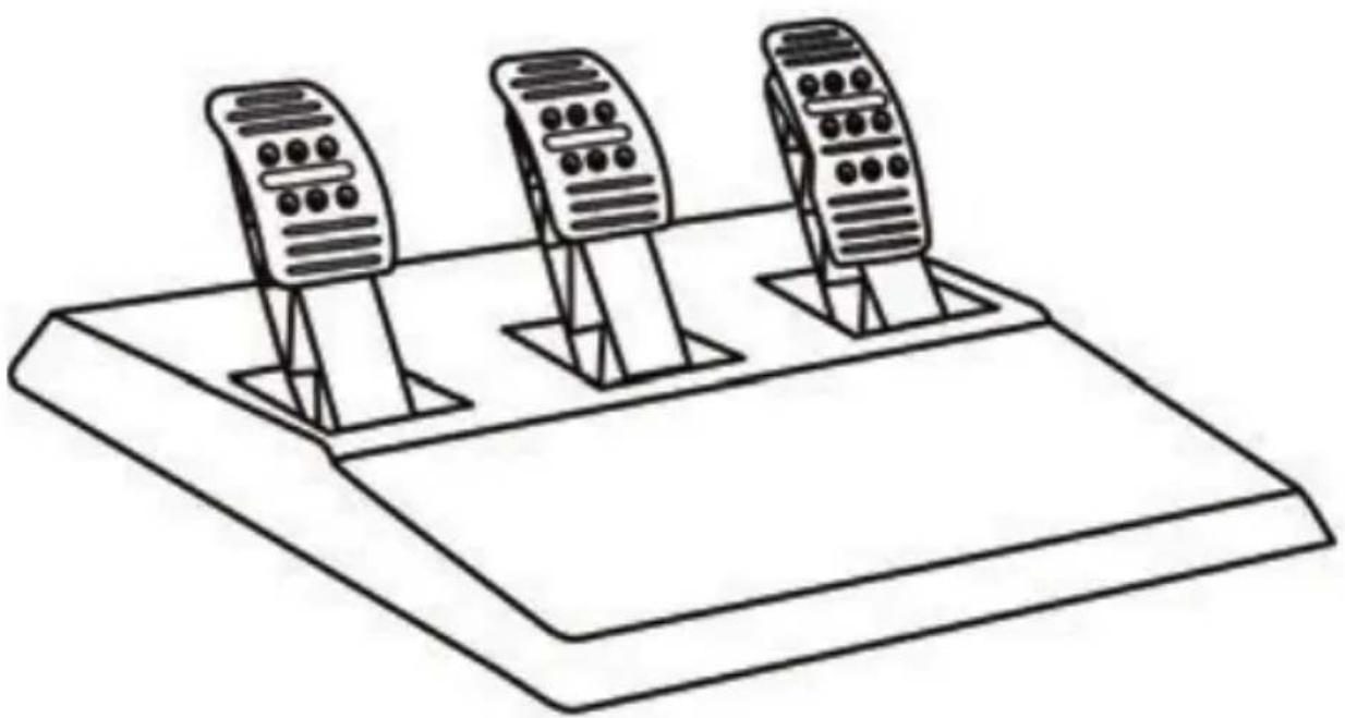
T3PA THRUSTMASTER 3 PEDALS ADD-ON
natural_image
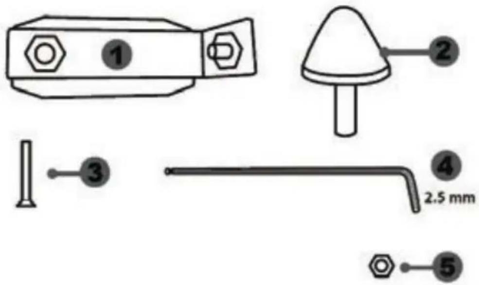
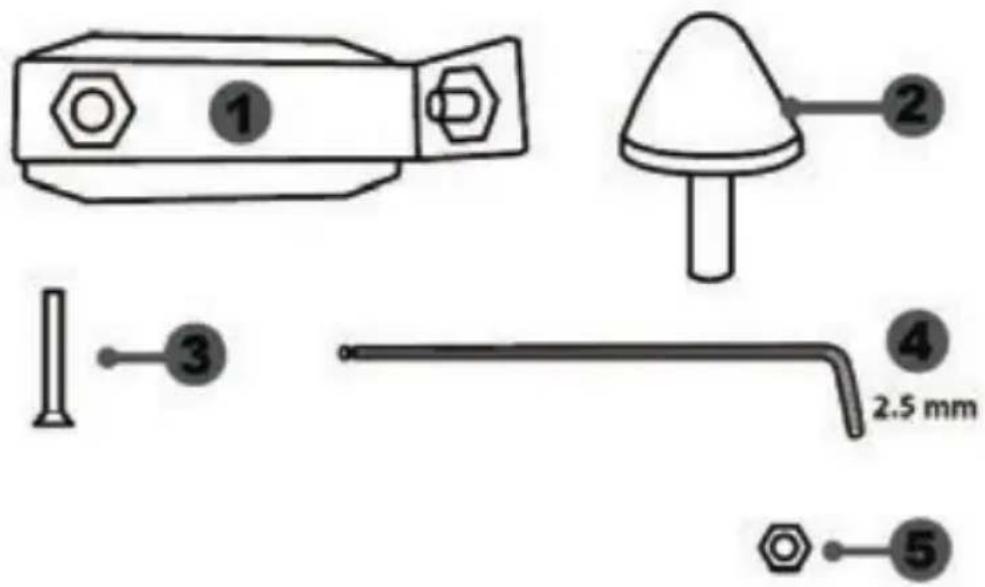
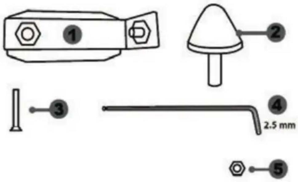
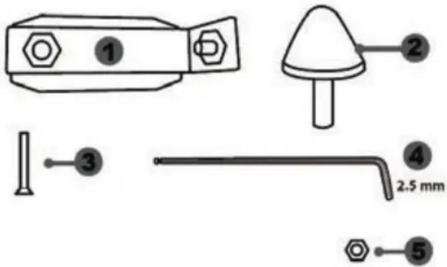
Line drawing of three speed limit switches mounted on a base (no text or symbols)TECHNICAL FEATURES

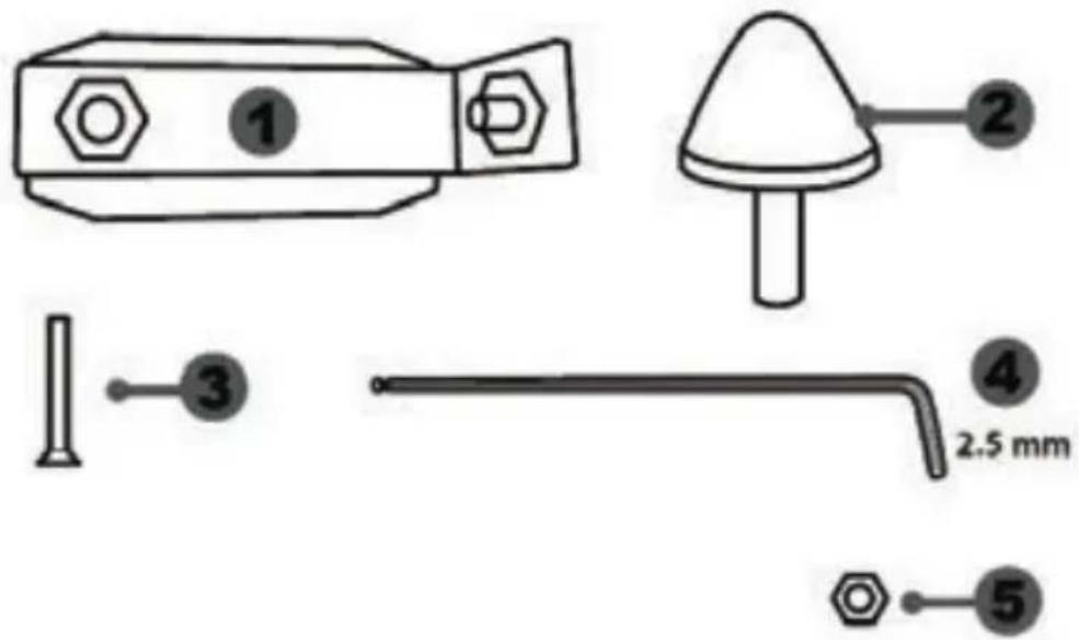
1 Metal support for conical stop (not installed by default)
2 Conical stop
3 Attachment screw for metal support
4 2.5 mm Allen key (included)
5 Position adjustment nut for conical stop
natural_image
Simple line drawing of a door with two dots and a numbered label (6) pointing to the side panel (no text or symbols on the door itself)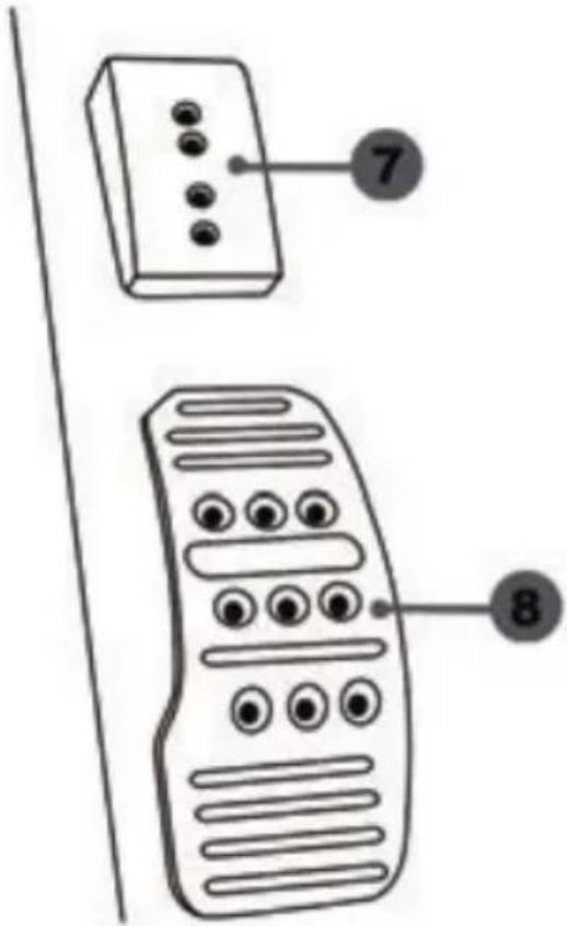
6 Pedal arm
7 Plastic head support
8 Metal pedal head
WARNING
Before using this product, be sure to read these instructions carefully and save them for future reference.

For safety reasons, never use the pedal set with bare feet or while wearing only socks on your feet.
THRUSTMASTER® DISCLAIMS ALL RESPONSIBILITY IN THE EVENT OF INJURY RESULTING FROM USE OF THE PEDAL SET WITHOUT SHOES.

Warning – Pedal set pinching hazard during gaming sessions
* Keep the pedal set out of the reach of children.
* During gaming sessions, never place your fingers or thumbs on or near the sides of the pedals.
* During gaming sessions, never place your fingers or thumbs on or near the rear base of the pedals.
* During gaming sessions, never place your fingers or thumbs on or near the front base of the pedals.
AUTOMATIC CALIBRATION OF PEDALS

- Never connect or disconnect the pedal set from the base of the wheel when the wheel is connected to the console or PC, or during gaming sessions, to avoid calibration problems.
= Always connect the pedal set to the wheel before connecting the wheel to the console or PC.
- Once the wheel has self-calibrated and the game has started, the pedals automatically calibrate themselves after being pressed a few times.
- Never press on the pedals when the wheel is self-calibrating or when your game is starting up, to avoid calibration problems.
- If the pedals are not functioning correctly or appear to be improperly calibrated, power off your console, completely disconnect your wheel, then reconnect all of the cables (including the power supply cable and the pedal set cable), power the console back on and restart your game.
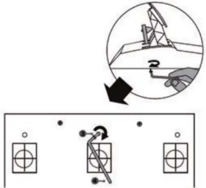
ATTACHING THE PEDAL SET TO A COCKPIT
- Attach the pedal set using the small screw threads located on the underside of the pedal set.
- Screw two M6 screws (not included) into the cockpit's pedal support plate and into the two small screw threads located on the underside of the pedal set.
Important: The length of the two M6 screws must not exceed the thickness of the cockpit's pedal support plate plus an additional 10 mm, to avoid damaging the pedal set's internal components.
ADJUSTING THE PEDAL SET
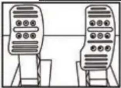
Each of the three pedals includes:
- A metal head (8) with multiple perforations (nine for the accelerator – six for the brake – six for the clutch).
- A plastic head support (7) (placed between the head and the arm) with four perforations.
- A pedal arm (6) with two perforations.
ATTENTION: To avoid any calibration problems, be sure to always disconnect your wheel's USB cable from the console or PC before making any adjustments to your pedal set.
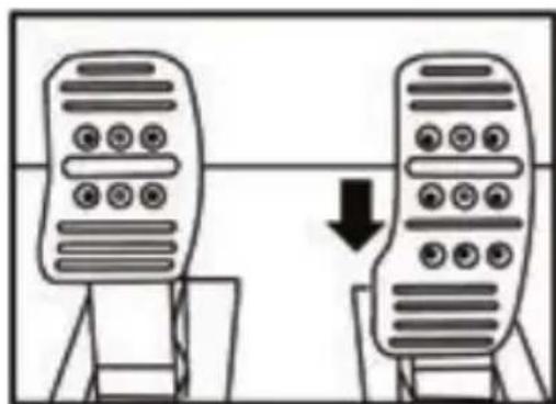
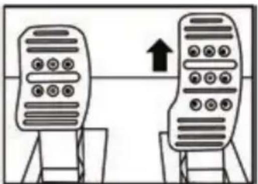
Adjusting the HEIGHT of the accelerator pedal
- Using the included 2.5 mm Allen key (4), unscrew the two screws holding the metal head (8) and its support (7) in place.
- Select your preferred height position, then replace and re-tighten the screws so that the metal head (8) and its support (7) are held firmly in place.
natural_image
Two identical server icons with circular buttons on their backs, connected by a downward arrow (no text or symbols)Low position (default)
natural_image
Two identical mobile phone icons with a bidirectional arrow between them (no text or symbols)High position
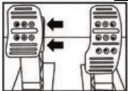
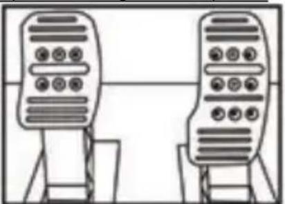
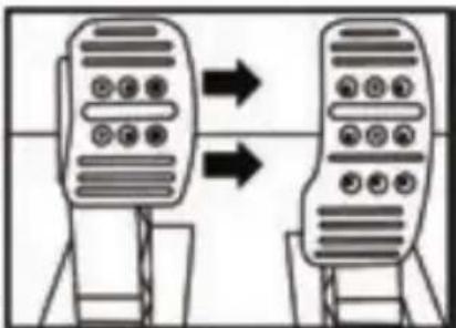
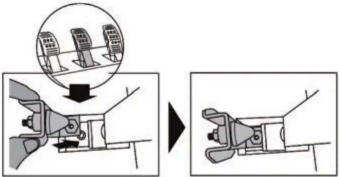
Adjusting the SPACING of the three pedals
- Using the included 2.5 mm Allen key (4), unscrew the two screws holding the metal head (8) and its support (7) in place.
- Select your preferred position (to the left, centered, or to the right), then replace and re-tighten the screws so that the metal head (8) and its support (7) are held firmly in place.
Examples illustrating the brake pedal:
flowchart
graph TD
    A["Device 1"] -->|Left Arrow| B["Device 2"]
    B -->|Right Arrow| A
Left position
natural_image
Two identical mobile phone controllers standing upright, no text or symbols visibleCentered position (default)
flowchart
graph LR
    A["Device 1"] --> B["Device 2"]
    B --> C["Device 3"]
    style A fill:#f9f,stroke:#333
    style B fill:#f9f,stroke:#333
    style C fill:#f9f,stroke:#333
Right position
Number of possible spacing positions per pedal:
- Three for accelerator pedal
- Three for brake pedal
- Three for clutch pedal
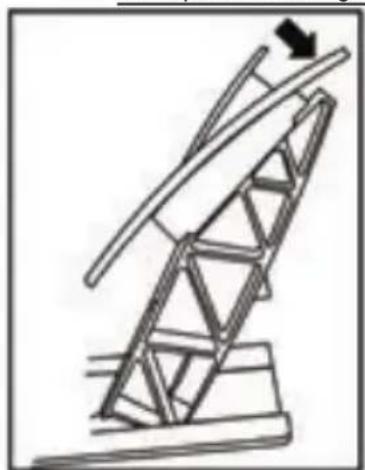
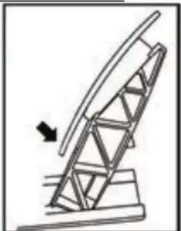
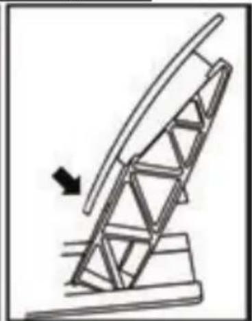
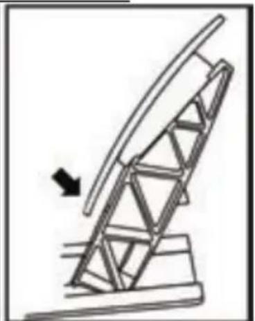
Adjusting the INCLINATION of the pedals
- Using the included 2.5 mm Allen key (4), unscrew the two screws holding the metal head (8) and its support (7) in place.
- Turn the plastic head support (7) 180°, then replace and re-tighten the screws so that the metal head (8) and its support (7) are held firmly in place.
Examples illustrating the accelerator pedal:
natural_image
Diagram of a mechanical structure with a ladder and support frame, no text or symbols presentLess inclined position
natural_image
Diagram of a mechanical structure with an arrow indicating direction, no text or symbols presentMore inclined position (default)
Number of possible inclination positions per pedal:
- Two for accelerator pedal
- Two for brake pedal
- Two for clutch pedal
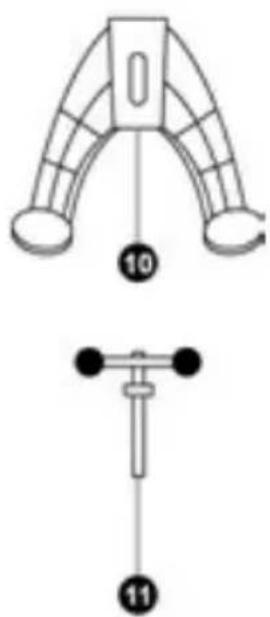
Installing the conical stop ("CONICAL RUBBER BRAKE" mod)
This modification (or "mod") is not essential, and is not installed by default. This means that the brake pedal functions perfectly even if the mod is not installed.
This mod lets you experience a different feeling and resistance when braking. It's up to you whether or not to install it, depending on your own preferences.
- Screw the conical stop (2) onto its metal support (1).
- Screw the position adjustment nut (5) onto the bottom (onto the conical stop's screw thread).
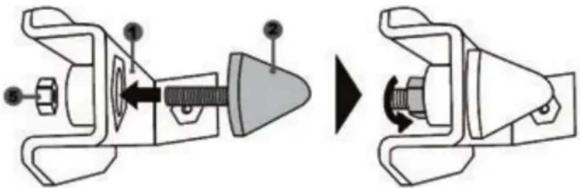
- Position the unit at the back of the brake pedal's arm.
- Using the included 2.5 mm Allen key (4), attach the unit using the attachment screw (3) and the small central screw thread located on the underside of the pedal set.
The "CONICAL RUBBER BRAKE" mod is now installed!
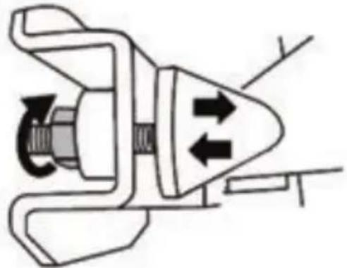
Adjusting the brake pedal's RANGE of travel and STRENGTH of resistance
By slightly unscrewing the nut (5), you can further strengthen the resistance of the brake pedal by moving the conical stop (2) closer to the back of the pedal's arm (if necessary, use a 14 mm wrench or pliers to re-tighten the nut and maintain the selected position). The closer the conical stop is positioned to the back of the pedal's arm, the greater the strength of resistance will be.
natural_image
Pure mechanical diagram of a valve or pump assembly without any text, numbers, or symbolsNote: When the conical stop is very close to the back of the brake pedal's arm, you may experience difficulties in reaching the maximum calibration value. Should that be the case:
* Slowly, press very hard on the brake pedal so as to reach the maximum value (if necessary, stand very briefly on the pedal – just for a second), then release the pressure; or else
* Move the conical stop a bit farther away from the back of the brake pedal's arm.
CONSUMER WARRANTY INFORMATION
Worldwide, Guillemot Corporation S.A., whose registered office is located at Place du Granier, B.P. 97143, 35571 Chantepie, France (hereinafter “Guillemot”) warrants to the consumer that this Thrustmaster product shall be free from defects in materials and workmanship, for a warranty period which corresponds to the time limit to bring an action for conformity with respect to this product. In the countries of the European Union, this corresponds to a period of two (2) years from delivery of the Thrustmaster product. In other countries, the warranty period corresponds to the time limit to bring an action for conformity with respect to the Thrustmaster product according to applicable laws of the country in which the consumer was domiciled on the date of purchase of the Thrustmaster product (if no such action exists in the corresponding country, then the warranty period shall be one (1) year from the original date of purchase of the Thrustmaster product).
Notwithstanding the above, rechargeable batteries are covered by a warranty period of six (6) months from the date of original purchase.
Should the product appear to be defective during the warranty period, immediately contact Technical Support, who will indicate the procedure to follow. If the defect is confirmed, the product must be returned to its place of purchase (or any other location indicated by Technical Support).
Within the context of this warranty, the consumer's defective product shall, at Technical Support's option, be either replaced or returned to working order. If, during the warranty period, the Thrustmaster product is subject to such reconditioning, any period of at least seven (7) days during which the product is out of use shall be added to the remaining warranty period (this period runs from the date of the consumer's request for intervention or from the date on which the product in question is made available for reconditioning, if the date on which the product is made available for reconditioning is subsequent to the date of the request for intervention). If permitted under applicable law, the full liability of Guillemot and its subsidiaries (including for consequential damages) is limited to the return to working order or the replacement of the Thrustmaster product. If permitted under applicable law, Guillemot disclaims all warranties of merchantability or fitness for a particular purpose.
This warranty shall not apply: (1) if the product has been modified, opened, altered, or has suffered damage as a result of inappropriate or abusive use, negligence, an accident, normal wear, or any other cause unrelated to a material or manufacturing defect (including, but not limited to, combining the Thrustmaster product with any unsuitable element, including in particular power supplies, rechargeable batteries, chargers, or any other elements not supplied by Guillemot for this product); (2) if the product has been used for any use other than home use, including for professional or commercial purposes (game rooms, training, competitions, for example); (3) in the event of failure to comply with the instructions provided by Technical Support; (4) to software, said software being subject to a specific warranty; (5) to consumables (elements to be replaced over the product's lifespan: disposable batteries, audio headset or headphone ear pads, for example); (6) to accessories (cables, cases, pouches, bags, wrist-straps, for example); (7) if the product was sold at public auction.
This warranty is nontransferable.
The consumer's legal rights with respect to laws applicable to the sale of consumer goods in his or her country are not affected by this warranty.
Additional warranty provisions
During the warranty period, Guillemot shall not provide, in principle, any spare parts, as Technical Support is the only party authorized to open and/or recondition any Thrustmaster product (with the exception of any reconditioning procedures which Technical Support may request that the consumer carry out, by way of written instructions – for example, due to the simplicity and the lack of confidentiality of the reconditioning process – and by providing the consumer with the required spare part(s), where applicable).
Given its innovation cycles and in order to protect its know-how and trade secrets, Guillemot shall not provide, in principle, any reconditioning notification or spare parts for any Thrustmaster product whose warranty period has expired.
In the United States of America and in Canada, this warranty is limited to the product's internal mechanism and external housing. In no event shall Guillemot or its affiliates be held liable to any third party for any consequential or incidental damages resulting from the breach of any express or implied warranties. Some States/Provinces do not allow limitation on how long an implied warranty lasts or exclusion or limitation of liability for consequential or incidental damages, so the above limitations or exclusions may not apply to you. This warranty gives you specific legal rights, and you may also have other rights which vary from State to State or Province to Province.
Liability
If permitted under applicable law, Guillemot Corporation S.A. (hereinafter “Guillemot”) and its subsidiaries disclaim all liability for any damages caused by one or more of the following: (1) the product has been modified, opened or altered; (2) failure to comply with assembly instructions; (3) inappropriate or abusive use, negligence, an accident (an impact, for example); (4) normal wear; (5) the use of the product for any use other than home use, including for professional or commercial purposes (game rooms, training, competitions, for example). If permitted under applicable law, Guillemot and its subsidiaries disclaim all liability for any damages unrelated to a material or manufacturing defect with respect to the product (including, but not limited to, any damages caused directly or indirectly by any software, or by combining the Thrustmaster product with any unsuitable element, including in particular power supplies, rechargeable batteries, chargers, or any other elements not supplied by Guillemot for this product).

COPYRIGHT
© 2017 Guillemot Corporation S.A. All rights reserved. Thrustmaster® is a registered trademark of Guillemot Corporation S.A. All other trademarks are the property of their respective owners. Illustrations not binding. Contents, designs and specifications are subject to change without notice and may vary from one country to another. Made in China.
FCC STATEMENT
- This device complies with Part 15 of the FCC Rules. Operation is subject to the following two conditions:
(1) This device may not cause harmful interference, and
(2) This device must accept any interference received, including interference that may cause undesired operation.
- Changes or modifications not expressly approved by the party responsible for compliance could void the user's authority to operate the equipment.
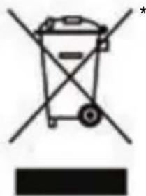
ENVIRONMENTAL PROTECTION RECOMMENDATION
natural_image
Symbol of a trash bin with crossed lines and a black rectangle below (no text or labels)In the European Union: At the end of its working life, this product should not be disposed of with standard household waste, but rather dropped off at a collection point for the disposal of Waste Electrical and Electronic Equipment (WEEE) for recycling.
This is confirmed by the symbol found on the product, user manual or packaging. Depending on their characteristics, the materials may be recycled. Through recycling and other forms of processing Waste Electrical and Electronic Equipment, you can make a significant contribution towards helping to protect the
environment.
Please contact your local authorities for information on the collection point nearest you.
For all other countries: Please adhere to local recycling laws for electrical and electronic equipment.
Retain this information. Colours and decorations may vary.
Plastic fasteners and adhesives should be removed from the product before it is used.
www.thrustmaster.com
*Applicable to EU and Turkey only


TX RACING WHEEL LEATHER EDITION
POUR XBOX ONE
natural_image
Technical line drawing of a steering wheel and three motors on a platform (no text or symbols)ATTENTION :

RELLER LE VOLANT AU SECTEUR = A LIRE IMPERATIVEMENT
natural_image
Line drawing of an electrical outlet with three leads and a terminal plug (no text or symbols)natural_image
Line drawing of an electric power plug with three leads and a terminal block (no text or symbols)natural_image
Symmetrical mechanical or electrical component diagram with concentric rings and central hub (no text or symbols)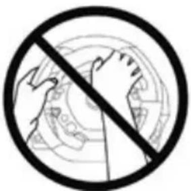
natural_image
Prohibition sign with a hand crossed out of a globe, no text or symbols present
natural_image
Prohibition sign showing a hand holding a circular object with a diagonal line (no text or symbols)
flowchart
graph TD
    A["Wheel with gear switch"] --> B["Gear shift"]
    B --> C["Motor assembly"]
    C --> D["Motor assembly"]
natural_image
Technical line drawing of a mechanical assembly with no visible text or symbols
natural_image
Technical line drawing of a mechanical component with no visible text or symbolsnatural_image
Technical line drawing of a mechanical component with an inset close-up showing internal components (no text or symbols)CAPTEUR DE TEMPERATURE INTERNE

natural_image
Line drawing of three speed limit switches mounted on a base (no text or symbols)CARACTERISTIQUES TECHNIQUES

natural_image
Two identical server icons with circular buttons on their backs, connected by a downward arrow (no text or symbols)natural_image
Two identical mobile phone controllers with one connected to a target device, no text or symbols presentPosition haute
natural_image
Two identical mobile phone controllers with left-pointing arrows indicating connection (no text or symbols)Position à gauche
natural_image
Two identical mobile phone controllers standing upright, no text or symbols visiblenatural_image
Diagram of a mechanical structure with a triangular frame and an arrow indicating upward motion (no text or symbols)natural_image
Diagram of a mechanical structure with an arrow indicating direction, no text or symbols present
natural_image
Mechanical component diagram showing a valve or connector with a rotating knob (no text or symbols)natural_image
Illustration of an oil pumpjack inside a circle with a hand holding a tool, no text or symbols present.
natural_image
Pure electrical circuit lines without any symbolsnatural_image
Pure mechanical diagram of a valve or connector without any text, numbers, or symbolsINFORMATIONS RELATIVES A LA GARANTIE AUX CONSOMMATEURS
natural_image
Symbol of a trash bin with crossed lines and a black rectangle below (no text or labels)www.thrustmaster.com
natural_image
Technical line drawing of a mechanical assembly and a multi-positioned device (no text or symbols)WARNUNG:
natural_image
Pure diagram of a symmetrical mechanical or architectural component with no text, numbers, or symbols
natural_image
Line drawing of an electrical outlet with two plug terminals and a cable (no text or symbols)
natural_image
Line drawing of an electric power plug with three leads and a terminal label (no text or symbols on the plug itself)
natural_image
Diagram of a mechanical or electrical component with concentric circular layers and directional arrows (no text or symbols)NIE
NIE


natural_image
Technical line drawing of a mechanical assembly with no visible text or symbols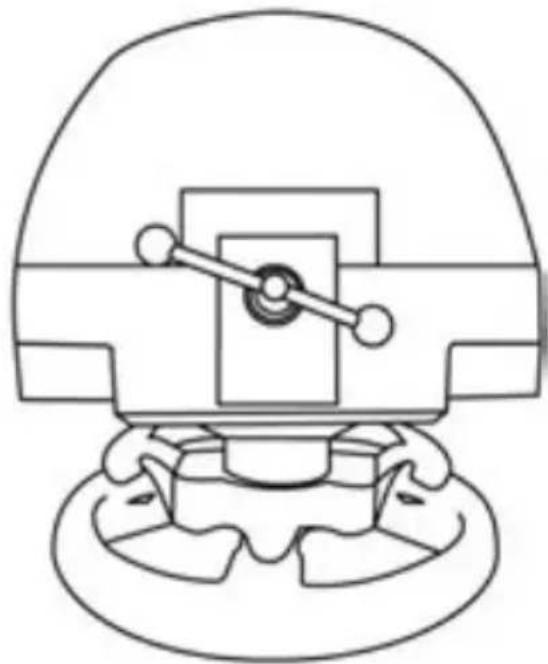
natural_image
Technical line drawing of a mechanical component with no visible text or symbolsnatural_image
Technical line drawing of a mechanical component with an inset close-up showing internal detail (no text or symbols)INTERNER TEMPERATUR-MESSFÜHLER
T3PA THRUSTMASTER 3 PEDALS ADD-ON
natural_image
Line drawing of three speed limit switches mounted on a base (no text or symbols)TECHNISCHE MERKMALE
EINBAU DES PEDALSETS IN EIN COCKPIT
ANPASSEN DES PEDALSETS
natural_image
Two identical mobile phone controllers with buttons and a downward arrow indicating interaction (no text or symbols)natural_image
Two identical mobile phone screens with circular buttons on stands, connected by a black arrow (no text or symbols)Hohe Position
natural_image
Two identical remote control devices with buttons and arrows indicating bidirectional movement (no text or symbols)Linke Position
natural_image
Two identical mobile phone controllers standing upright, no text or symbols visiblenatural_image
Diagram of a mechanical structure with a ladder and support frame, no text or symbols presentnatural_image
Diagram of a mechanical structure with an arrow indicating direction, no text or symbols presentnatural_image
Illustration of an oil pumpjack inside a circle with a hand holding a tool, no text or symbols present.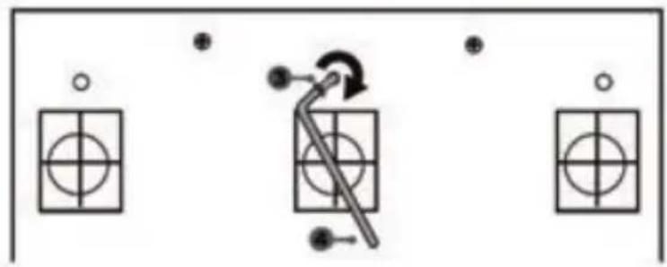
natural_image
Pure electrical circuit lines without any symbolsnatural_image
Diagram of a mechanical device with directional arrows indicating motion or force (no text or symbols)COPYRIGHT
natural_image
Symbol of a trash bin with crossed lines and a solid black rectangle below (no text or labels)www.thrustmaster.com
natural_image
Technical line drawing of a steering wheel and three control switches on a base (no text or symbols)WAARSCHUWING:

natural_image
Line drawing of an electrical outlet with two plug connectors and a cable (no text or symbols)
Steek de 220-240 V kabel
natural_image
Line drawing of an electric plug with three leads and a terminal label (no text or symbols on the plug itself)
Steek de 100-125 V kabel
natural_image
Symmetrical mechanical or electrical component diagram enclosed in a circular frame (no text or symbols)

natural_image
Prohibition sign showing a hand holding a car wheel, no text or symbols present

natural_image
Technical line drawing of a mechanical assembly with no visible text or symbols
natural_image
Technical line drawing of a mechanical component with no visible text or symbolsnatural_image
Technical line drawing of a mechanical component with an inset close-up showing internal components (no text or symbols)SENSOR VOOR INTERNE TEMPERATUUR
T3PA THRUSTMASTER 3 PEDALS ADD-ON
natural_image
Line drawing of three speed limit switches mounted on a base (no text or symbols)DE PEDAALSET AAN EEN COCKPIT BEVESTIGEN
natural_image
Two identical mobile phone controllers with a downward arrow indicating a change (no text or symbols present)natural_image
Two identical mobile phone screens with circular buttons on stands, connected by a horizontal line and an upward arrow (no text or symbols)Hoge stand
natural_image
Illustration of an oil pumpjack inside a circular frame with a hand holding a tool, no text or symbols present.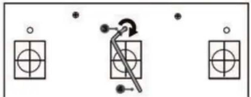
natural_image
Pure electrical circuit lines without any symbolsDe "CONICAL RUBBER BRAKE" mod is nu gemonteerd
natural_image
Diagram of a mechanical device with directional arrows indicating motion or force (no text or symbols)natural_image
Symbol of a trash bin crossed with diagonal lines, no text or labels presentwww.thrustmaster.com
natural_image
Technical line drawing of a steering wheel and three control switches on a base (no text or symbols)ATTENZIONE:
natural_image
Line drawing of an electrical plug with three leads and a terminal block, no text or symbols present
natural_image
Line drawing of an electric plug with two terminal leads and a cable (no text or symbols)
natural_image
Simple line drawing of two connected electrical plugs (no text or symbols)
ATTENZIONE
natural_image
Cross-sectional diagram of a mechanical or electrical component with concentric circles and internal components (no text or symbols)MAI

natural_image
Prohibition sign with hand holding a globe, no text or symbols presentMAI


natural_image
Technical line drawing of a mechanical assembly with no visible text or symbols
natural_image
Technical line drawing of a mechanical component with no visible text or symbolsnatural_image
Technical line drawing of a mechanical component with an inset close-up showing internal detail (no text or symbols)SENSORE TEMPERATURA INTERNA
T3PA THRUSTMASTER 3 PEDALS ADD-ON
natural_image
Line drawing of three speed limit switches mounted on a base (no text or symbols)CARATTERISTICHE TECNICHE
natural_image
Simple line drawing of a door with two dots and a numbered label (6) pointing to the side panel (no text or symbols on the door itself)natural_image
Two identical mobile phone controllers with buttons and a downward arrow indicating interaction (no text or symbols)natural_image
Two identical mobile phone screens with circular buttons on top, connected by a black arrow (no text or symbols)Posizione alta
natural_image
Two identical mobile phone controllers with left-pointing arrows indicating bidirectional connection (no text or symbols)natural_image
Two identical mobile phone controllers standing upright, no text or symbols visiblenatural_image
Diagram showing two views of a mechanical structure with arrows indicating motion direction (no text or symbols)natural_image
Pure mechanical diagram of a valve or pump assembly without any text, numbers, or symbolsnatural_image
Symbol of a trash bin crossed with no text or labels, representing waste sorting or disposal (no text present)www.thrustmaster.com
natural_image
Technical line drawing of a steering wheel and three control switches on a base (no text or symbols)AVISO:

natural_image
Line drawing of an electrical plug with three leads and a terminal block (no text or symbols)natural_image
Line drawing of an electric power plug with three leads and a terminal label (no text or symbols on the plug itself)natural_image
Symmetrical abstract diagram with concentric circles and curved lines, no text or symbols presentNUNCA
natural_image
Prohibition sign with hand holding a circular object, no text or symbols presentNUNCA

natural_image
Prohibition sign showing a hand holding a ring above a circular background (no text or symbols)
natural_image
Technical line drawing of a mechanical assembly with no visible text or symbols
natural_image
Technical line drawing of a mechanical component with no visible text or symbolsnatural_image
Technical line drawing of a mechanical component with an inset close-up showing internal components (no text or symbols)SENSOR DE TEMPERATURA INTERNO
T3PA THRUSTMASTER 3 PEDALS ADD-ON

natural_image
Line drawing of three speed limit switches mounted on a base (no text or symbols)CARACTERÍSTICAS TÉCNICAS
natural_image
Two identical server monitors connected by a double-headed arrow, no text or symbols presentnatural_image
Two identical mobile phone controllers with one up arrow, no text or symbols presentPosición alta
natural_image
Two identical mobile phone controllers standing upright, no text or symbols visiblenatural_image
Diagram of a mechanical structure with a ladder and support frame, no text or symbols presentnatural_image
Diagram of a mechanical structure with an arrow indicating direction, no text or symbols presentnatural_image
Illustration of an oil pumpjack inside a circle with a hand holding a tool, no text or symbols present.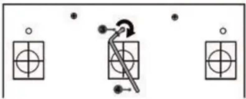
natural_image
Pure electrical circuit lines without any symbolsnatural_image
Pure mechanical diagram of a valve or pump assembly without any text, numbers, or symbolsCOPYRIGHT
natural_image
Symbol of a trash bin with cross-bracing and a black rectangle below (no text or labels)www.thrustmaster.com
natural_image
Technical line drawing of a steering wheel and three control switches on a platform (no text or symbols)ATENÇÃO:

natural_image
Line drawing of a three-pin electrical plug with a cable, showing terminal and terminal connections (no text or symbols)
Nunca ligue o cabo de 220-240 V
natural_image
Line drawing of an electrical outlet with three leads and a terminal block (no text or symbols)
natural_image
Simple line drawing of two connected electrical plugs (no text or symbols)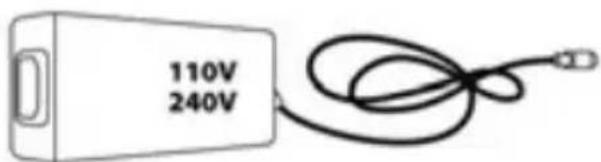
ATENÇÃO
natural_image
Abstract circular diagram with concentric rings and symmetrical patterns, no text or symbols present.NUNCA
natural_image
Prohibition sign with a hand holding a circular object, no text or symbols presentNUNCA
natural_image
Prohibition sign showing a hand holding a car wheel, no text or symbols present
flowchart
graph TD
    A["Wheel with gear assembly"] --> B["Gear assembly"]
    B --> C["Motor assembly"]
    C --> D["Motor assembly"]
natural_image
Technical line drawing of a mechanical assembly with no visible text or symbols
natural_image
Technical line drawing of a mechanical component with no visible text or symbolsnatural_image
Technical line drawing of a mechanical component with an inset close-up showing internal components (no text or symbols)SENSOR DE TEMPERATURA INTERNA
T3PA THRUSTMASTER 3 PEDALS ADD-ON

natural_image
Line drawing of three speed limit switches mounted on a base (no text or symbols)CARACTERÍSTICAS TÉCNICAS

natural_image
Simple line drawing of a domino with two dots and a numbered label (6) pointing to the side panel (no text or symbols on the diagram itself)FIXAR O CONJUNTO DE PEDAIS A UM COCKPIT
- Fixe o conjunto de pedais utilizando as pequenas roscas de parafusos situadas na parte inferior do conjunto de pedais.
- Enrosque dois parafusos M6 (não incluídos) na chapa de apoio do conjunto de pedais e nas duas pequenas roscas de parafusos situadas na parte inferior do conjunto de pedais.
natural_image
Two identical server icons with circular buttons on their backs, connected by a downward arrow (no text or symbols)natural_image
Two identical mobile phone controllers with buttons and a bidirectional arrow between them (no text or symbols)Posição alta
natural_image
Two identical mobile phone controllers standing upright, no text or symbols visiblenatural_image
Diagram of a ladder structure with an upward arrow indicating motion (no text or symbols)natural_image
Diagram of a mechanical structure with an arrow indicating direction, no text or symbols presentnatural_image
Illustration of an oil pumpjack inside a circular frame with a hand holding a tool, no text or symbols present.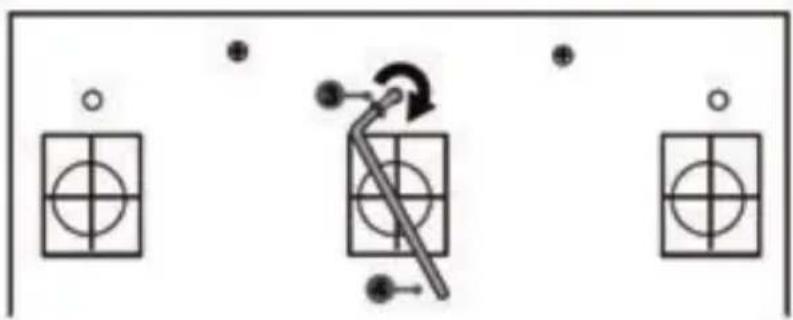
natural_image
Pure mechanical diagram showing a lever mechanism with circular components and alignment indicators (no text or symbols)natural_image
Diagram of a mechanical device with directional arrows indicating motion or force (no text or symbols)natural_image
Simple line drawing of a trash bin with cross-bracing and a blank rectangular base (no text or symbols)www.thrustmaster.com
natural_image
Technical line drawing of a steering wheel and three control switches on a platform (no text or symbols)ВНИМАНИЕ!
natural_image
Line drawing of an electrical plug with three leads and a terminal block (no text or symbols)
natural_image
Line drawing of an electrical outlet with two terminal plugs and a cable (no text or symbols)
natural_image
Simple line drawing of two connected electrical plugs (no text or symbols)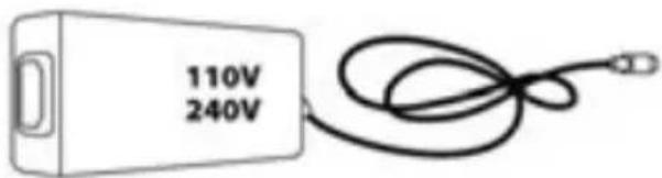
ВНИМАНИЕ!
natural_image
Pure mechanical component diagram without any text, numbers, or symbolsНЕЛЬЗЯ

natural_image
Prohibition sign with hand holding a circular diagram, no text or symbols presentНЕЛЬЗЯ

natural_image
Prohibition sign with hand holding a pen, crossed out by a diagonal line (no text or symbols)НЕЛЬЗЯ
natural_image
Prohibition sign with hand holding a pen, crossed out by a diagonal line (no text or symbols)НЕЛЬЗЯ


flowchart
graph TD
    A["Top: Gear with circular head and gear assembly"] --> B["Central gear assembly"]
    B --> C["Bottom: Gear assembly with hand and tool"]
    C --> D["Final Assembly"]
natural_image
Technical line drawing of a mechanical component with an inset close-up showing internal components (no text or symbols)T3PA THRUSTMASTER 3 PEDALS ADD-ON

natural_image
Line drawing of three speed limit switches mounted on a base (no text or symbols)6 Рычаг педали
natural_image
Two identical server monitors connected by a double-headed arrow, no text or symbols presentnatural_image
Two identical mobile phone screens with a central up arrow, no text or symbols presentВысокое положение
natural_image
Two identical mobile phone controllers standing upright, no text or symbols visiblenatural_image
Diagram of a mechanical structure with a ladder and support frame, no text or symbols presentУгол наклона меньше
natural_image
Diagram of a mechanical structure with an arrow indicating direction, no text or symbols presentnatural_image
Illustration of an oil pumpjack inside a circle with a hand holding a tool, no text or symbols present.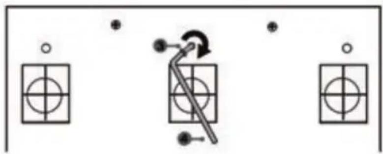
natural_image
Pure electrical circuit lines without any symbolsМодуль CONICAL RUBBER BRAKE mod установлен!
natural_image
Pure mechanical diagram of a valve or connector without any text, numbers, or symbolswww.thrustmaster.com
EAC


TX RACING WHEEL LEATHER EDITION
ΓΙΑ ΧΒΟΧ ΟΝΕ
Εγχειρίδιο χρήσης

natural_image
Technical line drawing of a steering wheel and three control switches on a platform (no text or symbols)ΠΡΟΕΙΔΟΠΟΙΗΣΗ:

natural_image
Technical line drawing of a mechanical component with two views (top: curved arms, bottom: vertical rod with circular ends), no text or symbols present.natural_image
Line drawing of a three-pin electrical plug with a cable, no text or symbols presentnatural_image
Line drawing of an electric power plug with three leads and a terminal label (no text or symbols on the plug itself)natural_image
Abstract circular diagram with concentric rings and symmetrical internal patterns, no text or symbols present.ПОТЕ

ПОТЕ

flowchart
graph TD
    A["Wheel with clockwise head"] --> B["Gear shift"]
    B --> C["Motor drive"]
    C --> D["Motor drive mechanism"]
natural_image
Technical line drawing of a mechanical assembly with no visible text or symbols
natural_image
Technical line drawing of a mechanical component with no visible text or symbolsnatural_image
Technical line drawing of a mechanical component with an inset close-up showing internal components (no text or symbols)T3PA THRUSTMASTER 3 PEDALS ADD-ON

natural_image
Line drawing of three speed limit switches mounted on a base (no text or symbols)TEXNIKA XAPAKTHPISTIKA
natural_image
Two identical server icons with circular buttons on stands, connected by a downward arrow (no text or symbols)natural_image
Two identical mobile phone screens with a black upward arrow between them, no text or symbols present.Υψηλή θέση
natural_image
Diagram showing two views of a mechanical structure with arrows indicating motion direction (no text or symbols)natural_image
Illustration of an oil pumpjack inside a circular frame with a hand holding a tool, no text or symbols present.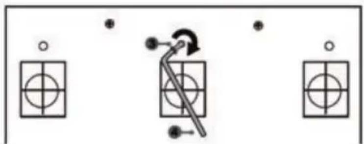
natural_image
Pure electrical circuit lines without any symbolsnatural_image
Pure mechanical diagram of a valve or connector without any text, numbers, or symbolsnatural_image
Symbol of a trash bin crossed with a diagonal line and a black rectangle below (no text or labels)www.thrustmaster.com
natural_image
Technical line drawing of a steering wheel and three control switches on a platform (no text or symbols)UYARI:
natural_image
Line drawing of an electrical outlet with three leads and a terminal plug (no text or symbols)
natural_image
Line drawing of an electrical outlet with two terminal leads and a cable (no text or symbols)
natural_image
Abstract circular diagram with concentric rings and symmetrical patterns, no text or symbols present.ASLA
natural_image
Prohibition sign with hand holding a globe, no text or symbols presentASLA

natural_image
Prohibition sign showing a hand holding a ring above a car wheel (no text or symbols)
flowchart
graph TD
    A["Top: Gear with circular head and gear assembly"] --> B["Left: Gear assembly with central hub and wheel"]
    B --> C["Right: Gear assembly with central hub and gear assembly"]
    C --> D["Bottom: Assembly with hand and tool"]
    D --> E["Final: Final assembly with hand and tool"]
natural_image
Technical line drawing of a mechanical assembly with no visible text or symbols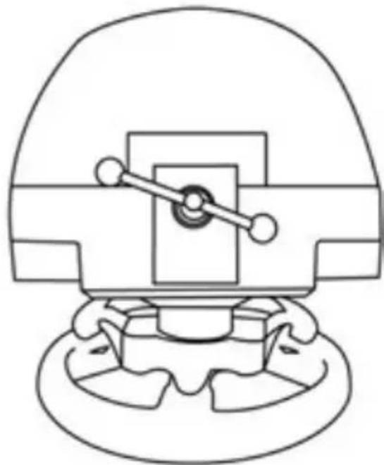
natural_image
Pure mechanical component diagram without any text, numbers, or symbolsnatural_image
Technical line drawing of a mechanical component with an inset close-up showing internal components (no text or symbols)DAHİLİ SICAKLIK SENSÖRÜ
T3PA THRUSTMASTER 3 PEDALS ADD-ON
natural_image
Line drawing of three speed limit switches mounted on a base (no text or symbols)TEKNİK ÖZELLİKLER
natural_image
Two identical mobile phone controllers with buttons and a downward arrow indicating change (no text or symbols)natural_image
Two identical mobile phone controllers with one connected to a target device (no text or symbols visible)Yüksek pozisyon
natural_image
Two identical mobile phone controllers standing upright, no text or symbols visiblenatural_image
Diagram of a mechanical structure with a ladder and support frame, no text or symbols presentAz eğimli pozisyon
natural_image
Diagram of a mechanical structure with an arrow indicating direction, no text or symbols present"CONICAL RUBBER BRAKE" mod şimdi monteli!
natural_image
Diagram of a mechanical device with directional arrows indicating motion or force (no text or symbols)www.thrustmaster.com
natural_image
Technical line drawing of a steering wheel and three control switches on a platform (no text or symbols)OSTRZEŻENIE:
natural_image
Line drawing of a three-pin electrical plug with a cable, no text or symbols present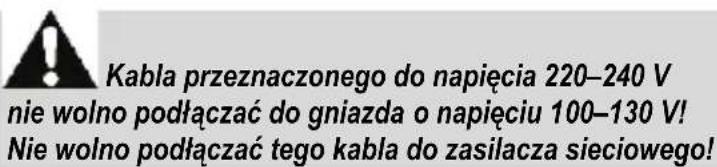
natural_image
Line drawing of an electric power plug with three leads (no text or symbols)
natural_image
Pure mechanical component diagram without any text, numbers, or symbolsNIGDY

natural_image
Prohibition sign with crossed hands forming a circular diagram (no text or symbols)NIGDY


natural_image
Technical line drawing of a mechanical assembly with no visible text or symbols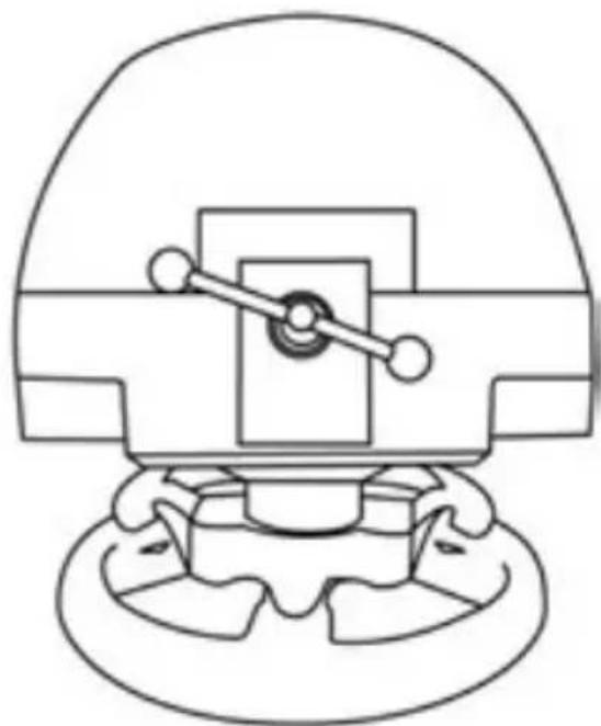
natural_image
Technical line drawing of a mechanical component with no visible text or symbolsnatural_image
Technical line drawing of a mechanical component with an inset close-up showing internal components (no text or symbols)WEWNETRZNY CZUJNIK TEMPERATURY
T3PA THRUSTMASTER 3 PEDALS ADD-ON

natural_image
Line drawing of three speed limit switches mounted on a base (no text or symbols)ELEMENTY
natural_image
Two identical server icons with circular buttons on their backs, connected by a downward arrow (no text or symbols)natural_image
Two identical mobile phone icons on stands, one with a black upward arrow between them (no text or symbols)Położenie wysokie
natural_image
Two identical mobile phone controllers standing upright, no text or symbols visiblenatural_image
Diagram of a mechanical structure with a ladder and support frame, no text or symbols presentMniejsze nachylenie
natural_image
Diagram of a mechanical structure with an arrow indicating direction, no text or symbols present
natural_image
Mechanical component diagram showing a valve or actuator with a rotating knob (no text or symbols)natural_image
Illustration of a mechanical assembly with a magnified inset showing three cylindrical components (no text or symbols present)
natural_image
Technical line drawing of a mechanical assembly (no text or symbols)natural_image
Mechanical component diagram showing a valve mechanism with directional arrows (no text or labels)www.thrustmaster.com
natural_image
Technical line drawing of a steering wheel and three control switches on a platform (no text or symbols)تحذير:
Xbox Guide 7
8 مصباح مؤشر أبيض
Thrustmaster Quick Release 12
natural_image
Diagram of a mechanical or electrical component with concentric rings and directional arrows, no text or symbols present.مطلقا

مطلاً

natural_image
Prohibition sign showing a hand holding a car wheel, no text or symbols presentnatural_image
Prohibition sign with diagonal line crossing over a hand holding a pen (no text or symbols)مطلقا
natural_image
Prohibition sign with diagonal line crossing over hands holding a pen (no text or symbols)مطلقا
flowchart
graph TD
    A["Wheel with gear switch"] --> B["Gear shift"]
    B --> C["Motor assembly"]
    C --> D["Motor assembly"]
natural_image
Technical line drawing of a mechanical component with an inset close-up showing internal detail (no text or symbols)T3PA THRUSTMASTER 3 PEDALS ADD-ON
natural_image
Line drawing of three speed limit switches mounted on a base (no text or symbols)الميزات التقنية
natural_image
Two identical mobile phone controllers with buttons and a downward arrow indicating interaction (no text or symbols)natural_image
Two identical mobile phone screens with buttons and a black upward arrow between them (no text or symbols)الوضع المرتفع
flowchart
graph TD
    A["Mobile Device 1"] -->|Bidirectional Arrow| B["Mobile Device 2"]
    B -->|Bidirectional Arrow| A
في يسار
natural_image
Two identical mobile phone controllers standing upright, no text or symbols visiblenatural_image
Diagram of a ladder structure with an arrow indicating upward motion (no text or symbols)وضعائل قليلا

natural_image
Diagram of a mechanical structure with an arrow indicating direction, no text or symbols present
natural_image
Mechanical component diagram showing a valve or connector with a rotating knob (no text or symbols)natural_image
Illustration of a mechanical device with a magnified inset showing three motor stators (no text or symbols present)
natural_image
Technical line drawing of a mechanical assembly (no text or symbols)natural_image
Illustration of an oil pumpjack inside a circular frame with a hand holding a tool, no text or symbols present.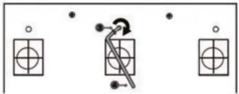
natural_image
Pure electrical circuit lines without any symbolsnatural_image
Pure mechanical diagram of a valve or connector without any text, numbers, or symbolswww.thrustmaster.com