N7 Z370 - Motherboard NZXT - Free user manual and instructions
Find the device manual for free N7 Z370 NZXT in PDF.
| Technical Specifications | Details |
|---|---|
| Motherboard Form Factor | ATX |
| Socket | Intel LGA 1151 |
| Chipset | Intel Z370 |
| Number of RAM Slots | 4 x DIMM |
| Maximum RAM Capacity | 64 GB |
| Supported RAM Type | DDR4 |
| PCIe Slots | 3 x PCIe 3.0 x16, 3 x PCIe 3.0 x1 |
| SATA Connectors | 6 x SATA III |
| USB Ports | USB 3.1 Gen 2, USB 3.1 Gen 1, USB 2.0 |
| Network | Ethernet 1 Gb/s |
| Integrated Audio | Realtek ALC1220 |
| Usage | Ideal for gaming and work setups |
| Maintenance | Regular BIOS update checks |
| Security | Surge protection, built-in security features |
| General Information | Compatible with 8th generation Intel processors |
Frequently Asked Questions - N7 Z370 NZXT
User questions about N7 Z370 NZXT
0 question about this device. Answer the ones you know or ask your own.
Ask a new question about this device
Download the instructions for your Motherboard in PDF format for free! Find your manual N7 Z370 - NZXT and take your electronic device back in hand. On this page are published all the documents necessary for the use of your device. N7 Z370 by NZXT.
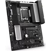
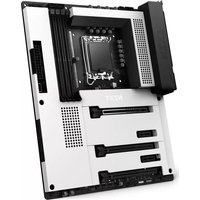
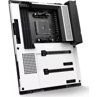
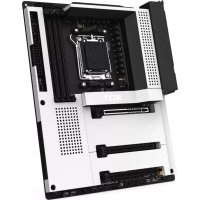
USER MANUAL N7 Z370 NZXT
Z370 ATX MOTHERBOARD
USER GUIDE
natural_image
Technical line drawing of a server rack with internal components and ventilation slots (no text or symbols)TABLE OF CONTENTS
1 PREFACE.... 1
2 PRODUCT INFORMATION
2.1 Package Contents.... 2
2.2 Specifications.... 3
3 COMPONENTS & PORTS
3.1 Covers.... 6
3.2 Ports Overview.... 8
3.3 Rear I/O.... 10
3.4 CPU Socket.... 12
3.5 DIMM Slots.... 14
3.6 PCI Express Expansion Slots.... 15
3.7 SATA Connectors.... 17
3.8 M.2 Slots.... 18
3.9 Power Connectors.... 20
3.10 USB 2.0 & 3.0 Connectors.... 21
3.11 Front Panel Audio Connector.... 22
3.12. Front Panel Connector.... 22
3.13. Fan Connectors.... 23
3.14. LED Connectors.... 23
3.15. Buttons & Switches.... 24
4 REGULATORY NOTICES...... A-1
5 SUPPORT AND SERVICE...... A-4
6 REGULATORY NOTICES...... A-6
7 BATTERY INFORMATION...... A-7
8 WEEE STATEMENT...... A-8
N7N7
1. PREFACE
A. Copyright© NZXT, Inc. All Rights Reserved.
This manual including all illustrations and screen captures, is protected under international copyright laws, with all rights reserved. Neither this manual, nor any of the material contained herein, may be reproduced without written consent of the author.
B. Disclaimer
The information in this document is subject to change without notice. The manufacturer makes no representations or warranties with respect to the contents hereof and specifically disclaims any implied warranties of merchantability or fitness for any particular purpose. The manufacturer reserves the right to revise this publication and to make changes from time to time in the content hereof without obligation of the manufacturer to notify any person of such revision or changes.
C. Trademark Recognition
Product names used in this manual are the properties of their respective owners and are acknowledged.
D. Safety Precaution
Follow these safety precautions when installing the motherboard:
- It is recommended to wear a grounding strap attached to a grounded device to avoid damage from static electricity.
- Discharge static electricity by touching the metal case of a safely grounded object before working on the motherboard.
- Leave components in the static-proof bags.
- Always remove the AC power by unplugging the power cord from the power outlet before installing or removing the motherboard or other hardware components.
2. PRODUCT INFORMATION
2.1 PACKAGE CONTENTS
• N7 Z370 Motherboard
- N7 Cover Pieces
- Motherboard User Guide
- I/O Shield
- 4x SATA Cables
• SLI Bridge Connector
- 2x LED Strips
• 2x 500mm LED Connection Cables
• 2x 300mm LED Extension Cable
2.2 SPECIFICATIONS
CPU & Socket
- LGA socket 1151 for Intel® 8th Generation Core™ i7/i5/i3 Processors
• Support Intel 14nm CPU
• Support Intel Turbo Boost Technology 2.0
Chipset
Intel® Z370
Memory
4x DIMM, Max. 64GB, DDR4
- 3866(O.C.)/ 3733(O.C.)/ 3600(O.C.)/ 3466(O.C.)/ 3400(O.C.)/ 3333(O.C.)/ 3300(O.C.)/ 3200(O.C.)/ 3000(O.C.)/ 2800(O.C.)/ 2666(O.C.)/ 2400(O.C.)/ 2133 MHz Non-ECC, Un-buffered Memory
- Dual-channel memory architecture
- Support Intel® Extreme Memory Profile (XMP)
Integrated Graphics
Multi-VGA output support: HDMI/DisplayPort 1.2 ports
- DisplayPort with max. resolution of 4096x2304@60Hz
- HDMI™ with max. resolution of 4096x2160@24Hz
• Maximum shared memory of 1024MB
Multi-GPU Support
• Supports NVIDIA® 2-Way SLI™ Technology
• Supports AMD 2-Way CrossFireX™ Technology
Storage
Intel® Z370 Express Chipset
- 1x M.2 type 2242/2260/2280 (PCIe 3.0 x4 & SATA mode)
- 1x M.2 type 2242/2260/2280 (PCIe 3.0 x4 mode only)
• 4x SATA 6Gb/s ports
Support RAID 0/1/5/10
Supports Intel® Smart Response Technology
Intel® Rapid Storage Technology
Intel® Optane Memory Ready
LAN
Intel® I219-V Gigabit LAN
Audio
Realtek® ALC1220 Codec
7.1-Channel High Definition Audio, 32-bit / 192KHz DAC
Expansion Slots
- 2x PCI-e 3.0 x16 (x16 or dual x8)
- 2x PCI-e 3.0 x4
- 1x PCI-e 3.0 x1
Rear I/O
- 5x USB 2.0 Ports
- 4 x USB 3.1 Gen 1 Ports
- 1x Display Port 1.2
• 1x HDMI™ 1.4b - 1x Clear CMOS Button
• 1x LAN (RJ45) Port
• 1x Optical S/PDIF Out Port
• 1x 7.1-Channel Audio Jacks
Operating System
Microsoft® Windows® 10 64-bit
Form Factor
ATX
Internal I/O
• 1x 24-pin EATX Power Connector
• 1x 8-pin ATX 12V Power Connector
- 1x 4-pin CPU_FAN Connector
- 1x 4-pin AIO_PUMP connector
- 1x 4-pin W_PUMP connector
- 6x 4-pin SYS_FAN Connectors
- 3x USB 2.0 Header (support up to 6 USB 2.0 ports)
- 2x USB 3.1 Gen 1 header (support up to 4 USB 3.1 Gen 1 ports)
• 4x SATA 6Gb/s Connectors
- 1x M.2 Socket 3 with M Key, (PCIe 3.0 x4 & SATA mode)
- 1x M.2 Socket 3 with M Key, (PCIe 3.0 x4 mode only)
- 2x LED Connectors
• 1x Noise Detection Module
• 1x Front Panel Audio Connector
- 1x Power Button
- 1x Reset Button
- 1x ROM Backup Button
- 1x Dual BIOS Switch
N7
3. COMPONENTS & PORTS
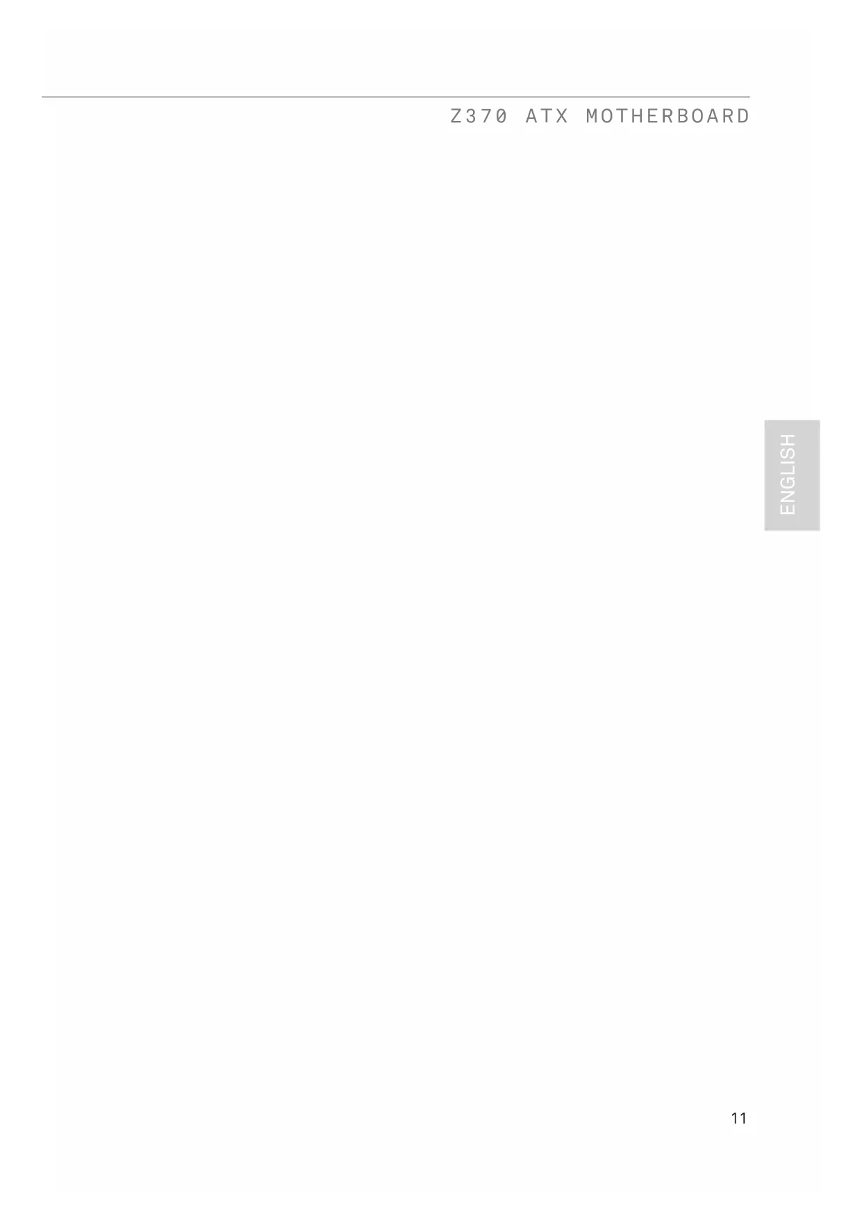
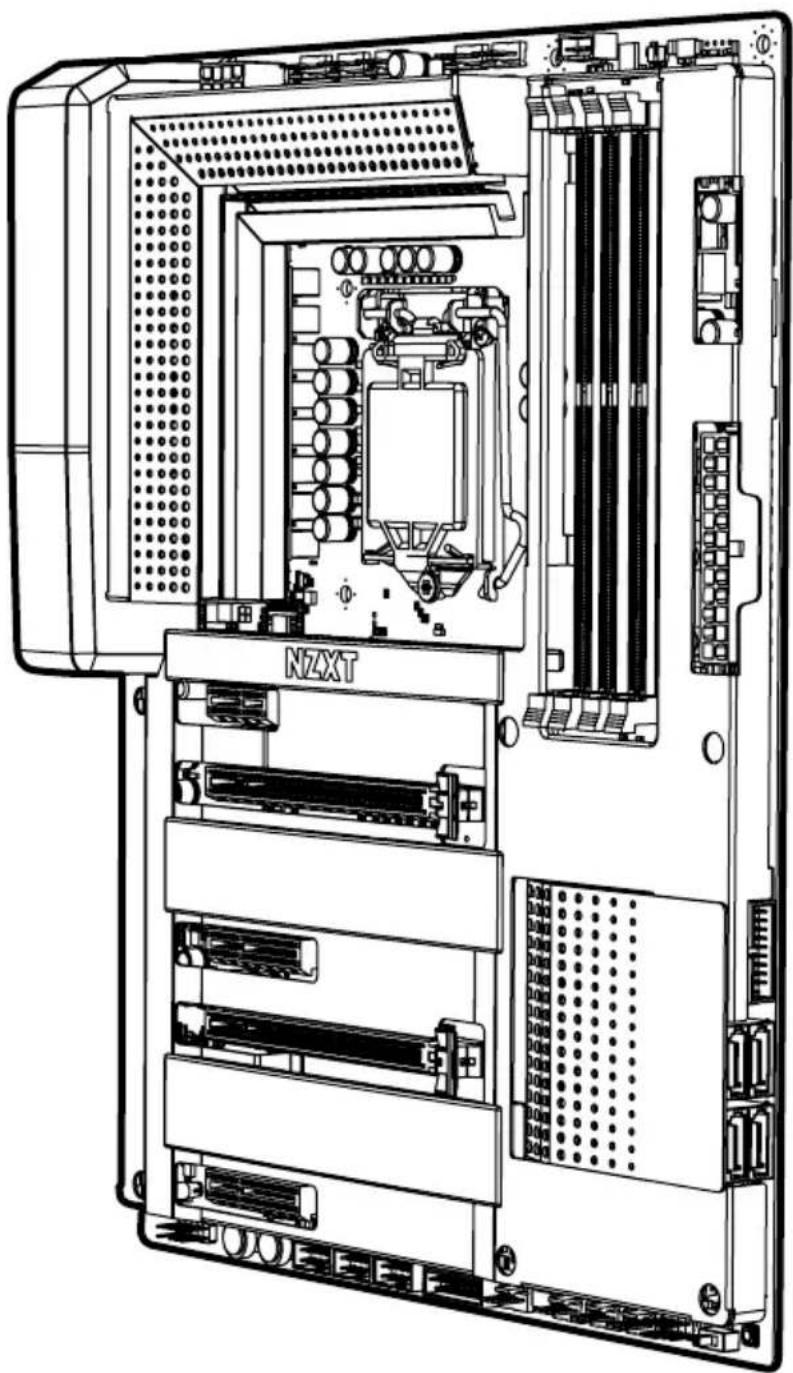
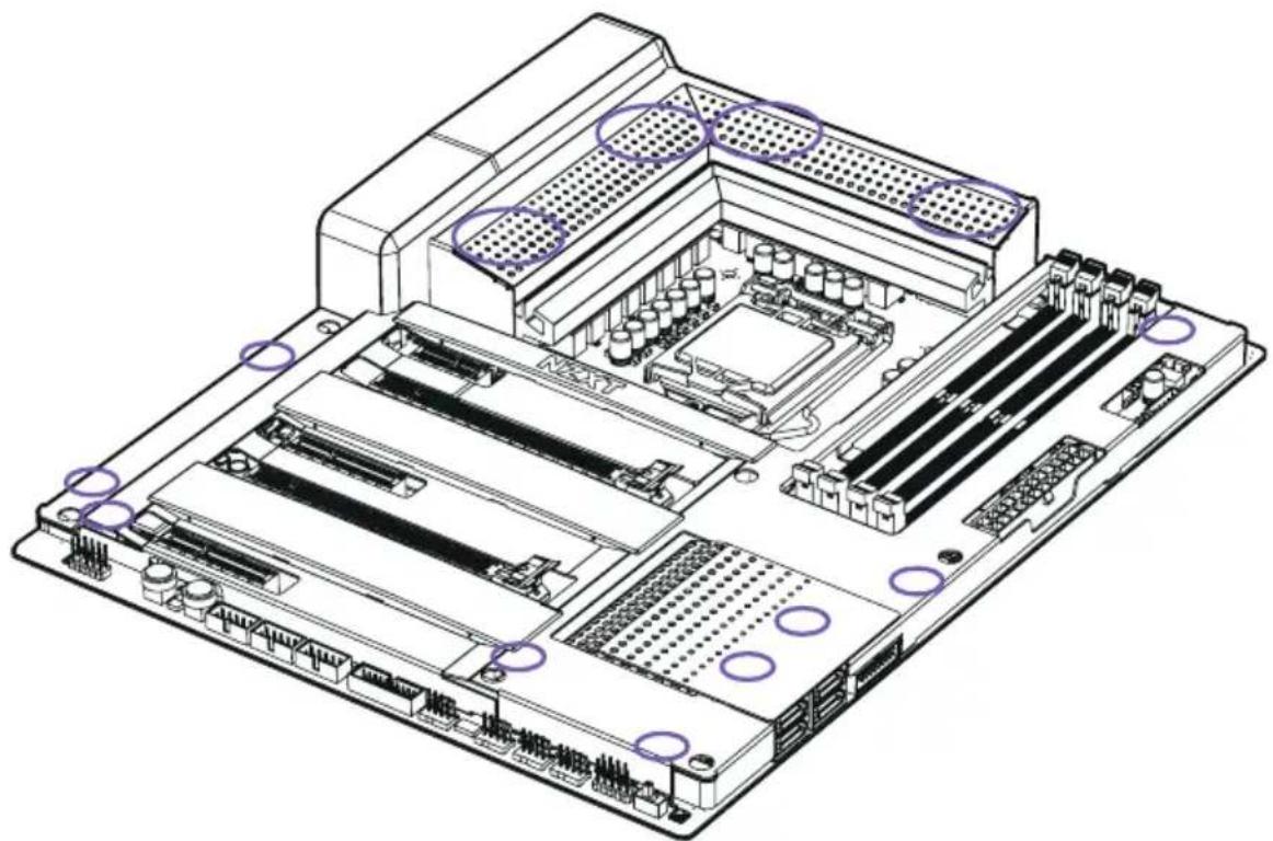
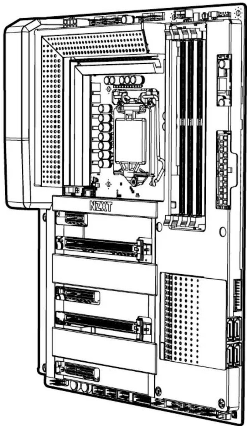
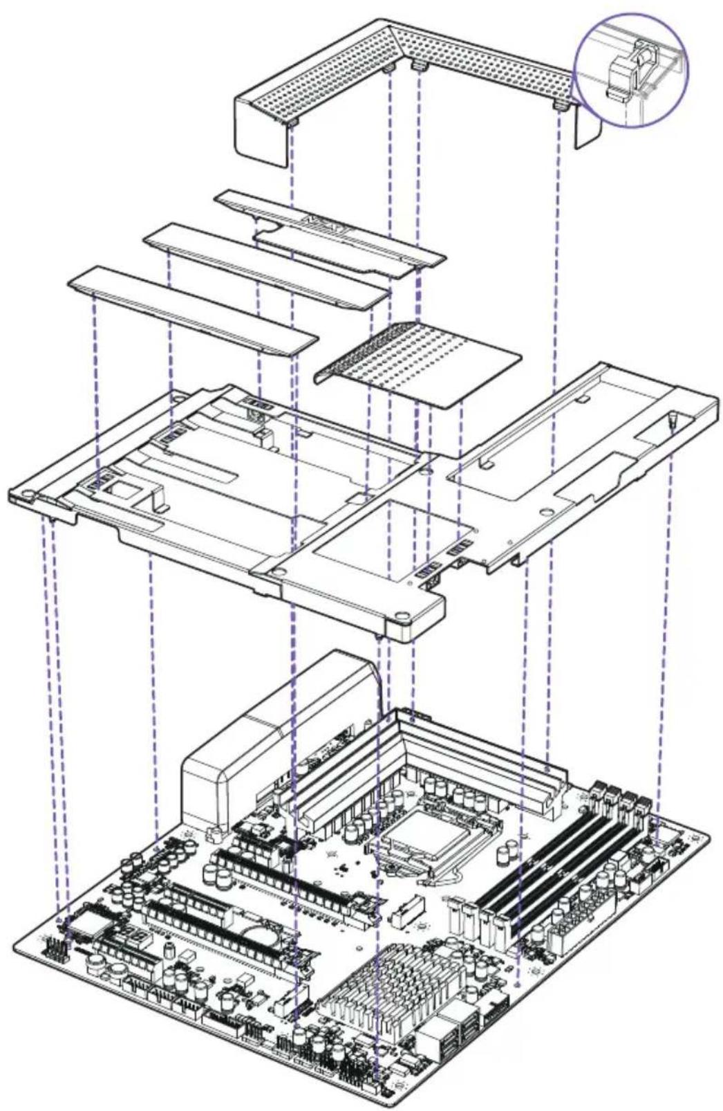
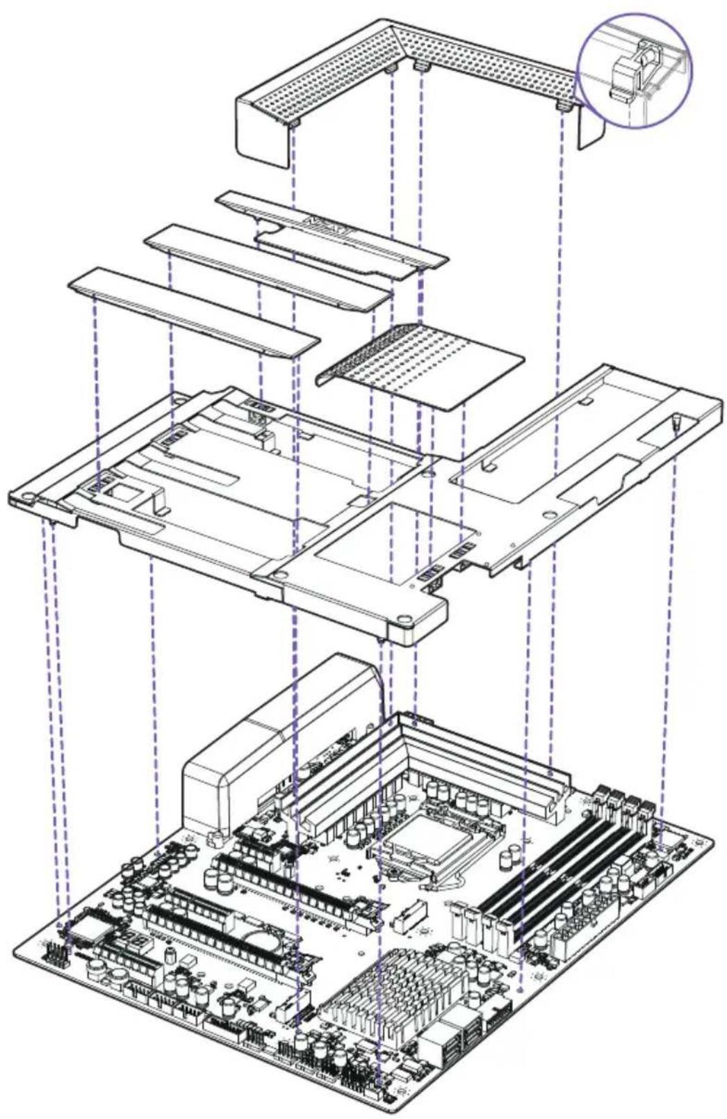
3.1 COVERS
Introduction
The cover pieces are latched onto the motherboard through multiple points. When installing and removing, please pay close attention to these points and apply an even force to prevent damage.
natural_image
Isometric technical diagram of a computer motherboard showing CPU socket, RAM slots, and ventilation ducts (no text or labels)Exploded View

natural_image
Exploded view diagram of a computer motherboard showing internal components and connections (no text or labels)3.2 PORTS OVERVIEW
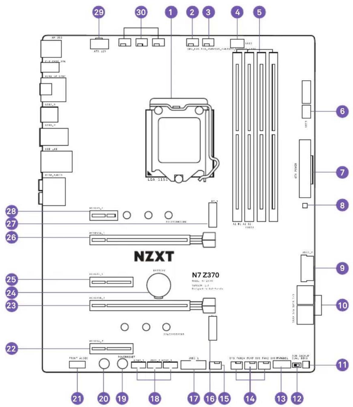
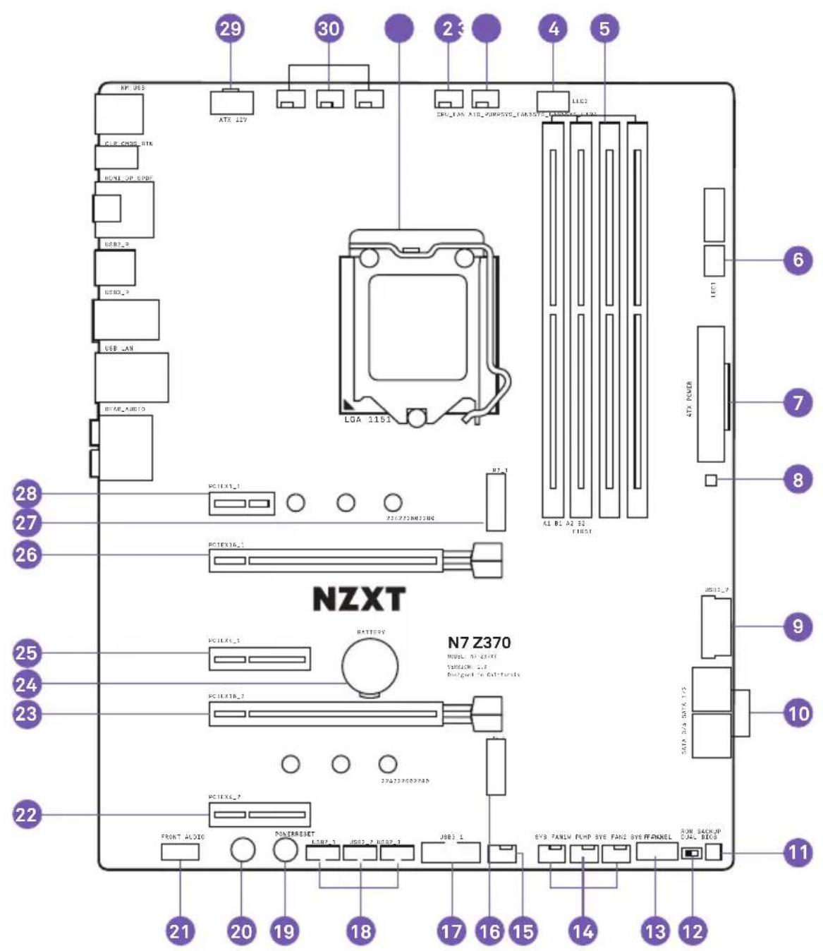
| No. | Port Name | Description |
| 1 | CPU Socket LGA 1151 socket for Intel 8th Generation processor | |
| 2 | CPU_FAN | 4-pin CPU fan connector |
| 3 | AIO_PUMP | 4-pin AIO pump connector |
| 4 | LED2 4-pin LED header | |
| 5 | DIMM A1-B2 | 288-pin DDR4 memory slots |
| 6 | LED1 4-pin LED header | |
| 7 | ATX_POWER 24-pin ATX power connector | |
| 8 | Noise Detection Module Digital noise detection module for CAM | |
| 9 | USB3_2 Front panel USB 3.1 Gen 1 header | |
| 10 | SATA 1-4 Serial ATA 6Gbps connectors | |
| 11 | ROM_BACKUP BIOS ROM backup button | |
| 12 | Dual BIOS Switch | Dual BIOS switch, toggle to the left for default |
| 13 | Front Panel Connectors | Front panel switches and LED connectors |
| 14 | SYS_FAN 1-3 | 4-pin fan connectors |
| 15 | W_PUMP | 4-pin connector for water pump |
| 16 | M2_2 | M.2 Socket 3 with M key, supports type2242/2260/2280 storage devices (SupportsPCIE & SATA mode) |
| 17 | USB3_1 Front panel USB 3.1 Gen 1 header | |
| 18 | USB2_1-3 | Front panel USB 2.0 headers |
| 19 | POWER Power button | |
| 20 | RESET Reset button | |
| 21 | FRONT_AUDIO | Front panel audio connector |
| 22 | PCIEX4_2 PCI Express x4 Gen3 slot | |
| 23 | PCIEX16_2 PCI Express x16 Gen3 slot for GPU | |
| 24 | Battery | Battery |
| 25 | PCIEX4_1 PCI Express x4 Gen3 slot | |
| 26 | PCIE16_1 | PCI Express x16 Gen3 slot for GPU |
| 27 | M2_1 | M.2 Socket 3 with M key, supports type2242/2260/2280 storage devices (Supports PCIEmode) |
| 28 | PCIEX1_1 PCI Express x1 Gen3 slot | |
| 29 | ATX_12V 8-pin +12V power connector | |
| 30 | SYS_FAN 4-6 | 4-pin fan connectors |
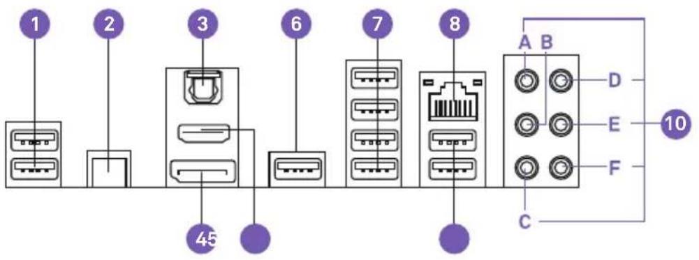
3.3 REAR I/O
text_image
1 2 3 6 7 8 45 A B D E F C 10No. Port Name
| 1 | USB 2.0 x 2 |
| 2 | Clear CMOS button |
| 3 | Optical SPDIF Out port |
| 4 | DisplayPort port |
| 5 | HDMI 1.4b port |
| 6 | USB 2.0 x 1 |
| 7 | USB 3.1 Gen 1 x 4 |
| 8 | RJ45 LAN port |
| 9 | USB 2.0 x 2 |
| 10 | Audio PortsA. Center and SubwooferB. Rear SurroundC. Side SurroundD. Line-inE. Front Left and RightF. Microphone |
Z370 ATX MOTHERBOARD
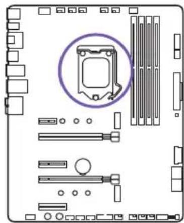
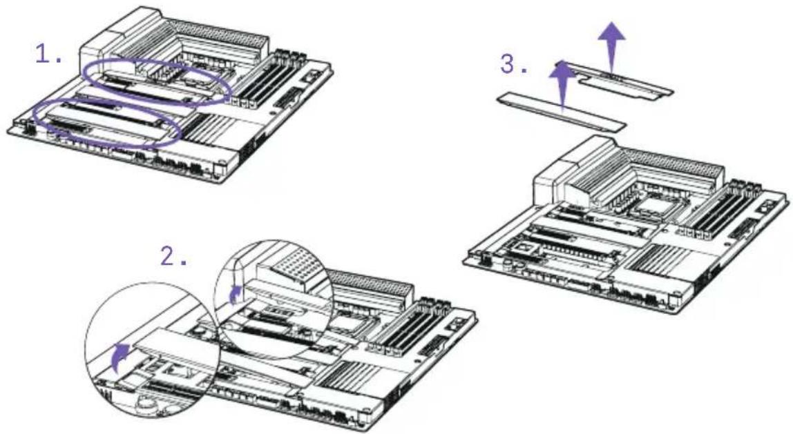
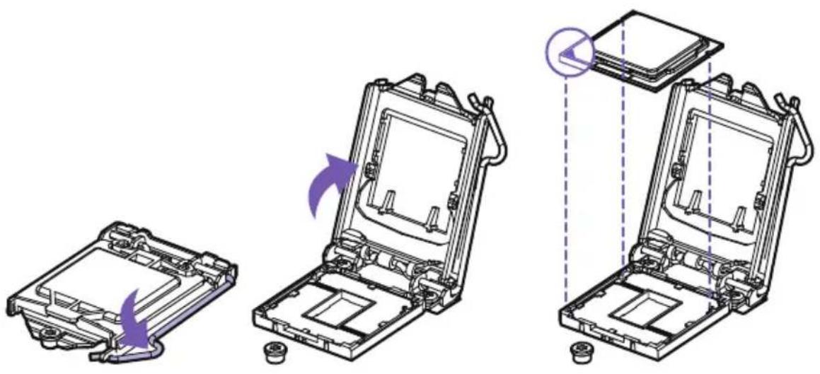
3.4 CPU SOCKET
Introduction
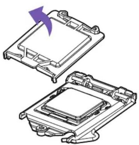
The surface of the LGA 1151 CPU has two notches and a golden triangle to assist in correctly lining up the CPU for placement within the socket.
natural_image
Top-down schematic of a computer motherboard showing slots, RAM slots, and a highlighted CPU socket (no text or labels)Installation
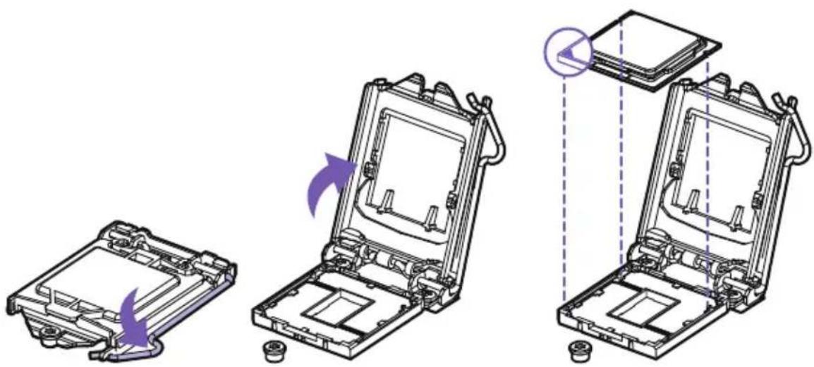
text_image
Technical diagram showing three stages of a device assembly with purple arrows indicating motion or transformation, likely illustrating a mechanical or electronic process.- Push down on the retention arm and outwards to release.
- Flip open the latch and place the CPU making sure the triangle and the notches on the CPU matches the corner as indicated.
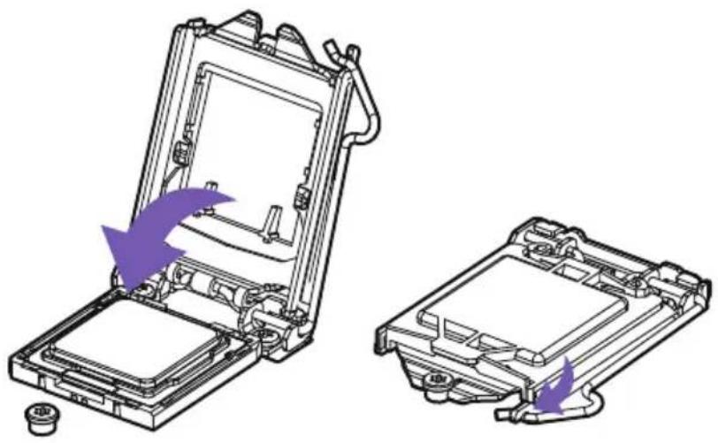
natural_image
Technical illustration of a device's internal components, showing two views with purple arrows indicating assembly or disassembly (no text or symbols present)- Close the latch and push down on the retention arm to lock it into place.
- The plastic protective cap will automatically become loosen.
natural_image
Technical line drawing of two electronic components with a purple arrow indicating rotation (no text or symbols)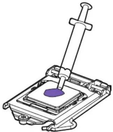
natural_image
Technical line drawing of a mechanical assembly with a purple component inserted into a housing (no text or symbols)- Apply thermal paste as needed and install your CPU cooler.

Note
• Always unplug the power cord from the power outlet before installing or removing the CPU.
- Please retain the CPU protective cap after installing the CPU.
- Confirm that the CPU heatsink has been mounted properly before booting.
- Whenever the CPU is not installed, always protect the CPU socket pins by covering the socket with the plastic protective cap.
- Please refer to the CPU cooler manufacturer's instructions to install your cooler.
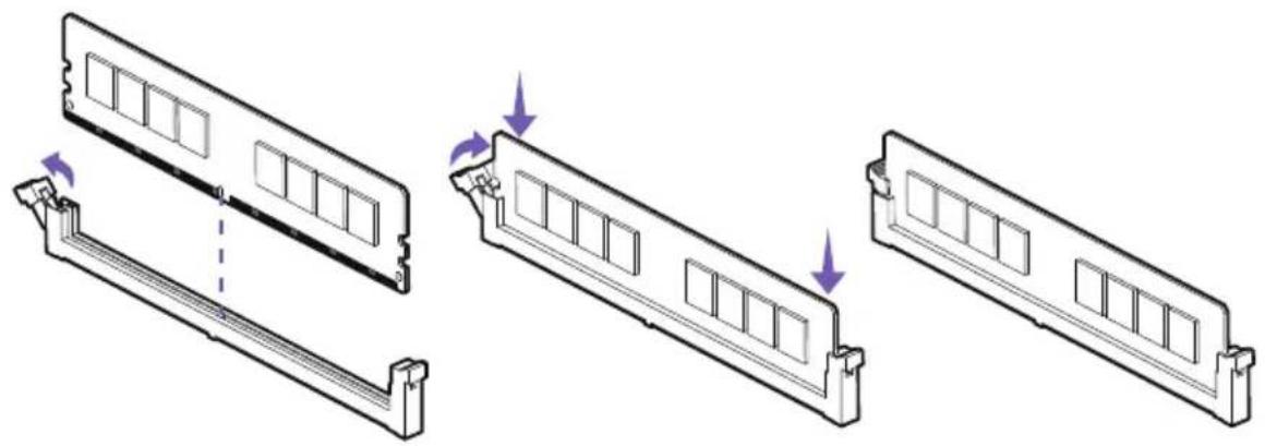
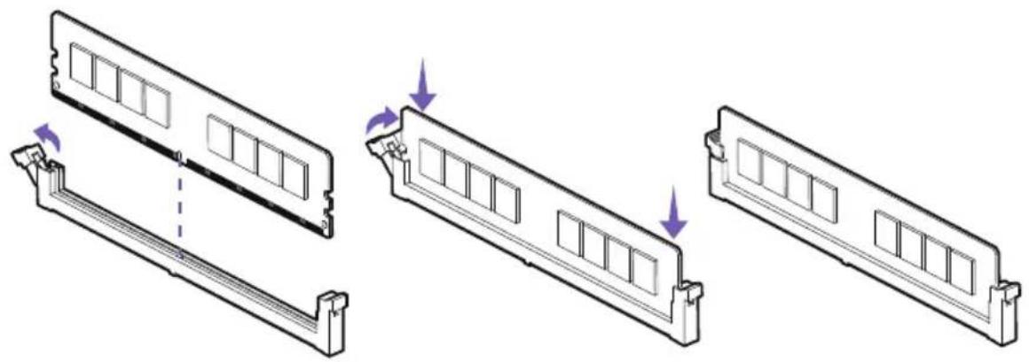
3.5 DIMM SLOTS
Introduction
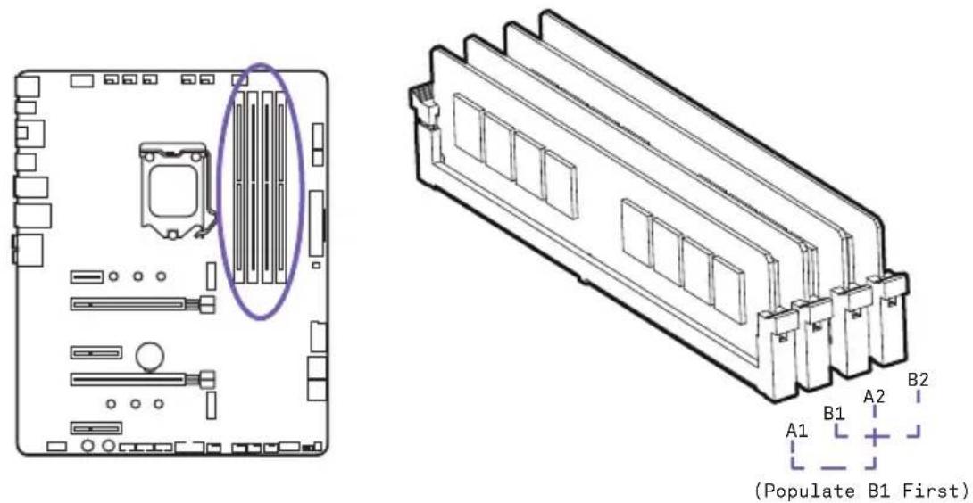
The DIMM slots are located here. Please see the diagram for recommended memory configuration.
text_image
(Populate B1 First)Installation
natural_image
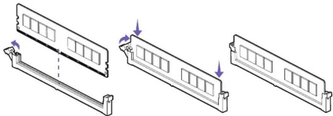
Diagram showing three views of a computer RAM module with mounting brackets and a dashed line indicating a transition point (no text or symbols present)- Push the release lever as indicated.
- Match the memory with the middle notch and align into the DIMM slots.
- Push the memory into the DIMM slot firmly until the level has been locked automatically.

Note
Insert memory modules in the B1 slot first.
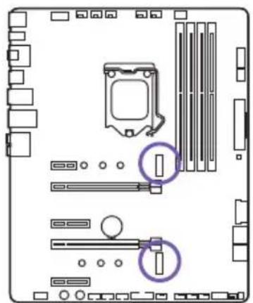
3.6 PCI EXPRESS EXPANSION SLOTS
Introduction
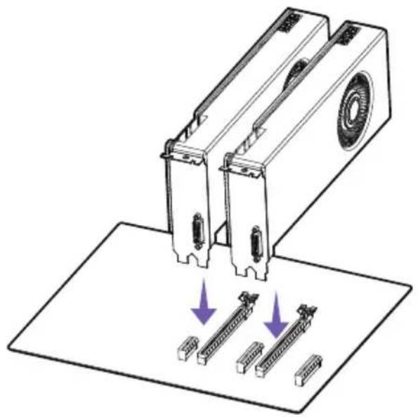
See the diagram below for the list of slots. Please install graphics cards using the PCIEX16_1 first then the PCIEX16_2.

text_image
PCIEX1_1: PCIe 3.0 x1 slot PCIEX16_1: PCIe 3.0 x16 slot PCIEX4_1: PCIe 3.0 x4 slot PCIEX16_2: PCIe 3.0 x8 slot PCIEX4_2 PCIe 3.0 x4 slotMulti-Graphic Cards Installation
For power supply recommendations for SLI configurations, please refer to the user guide of your graphics card to make sure you meet all the system requirements.
natural_image
Diagram of a mechanical device with two ports and three rows of connectors, showing directional arrows (no text or symbols)To install SLI graphics cards:
- Turn off your computer and disconnect the power cord, install two graphics cards into the PCIEX16_1 and PCIEX16_2 slots.
N7
natural_image
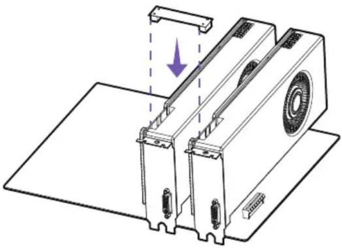
Technical line drawing of a mechanical device with no visible text or symbols- Connect the two cards together using the SLI Bridge Connector.
natural_image
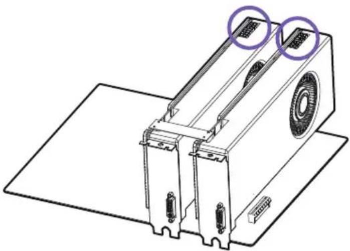
Technical line drawing of a mechanical device with two purple circular annotations highlighting features (no text or symbols present)- Connect all PCIe power connectors of the graphics cards.
- Reconnect the power cord, power up the computer and install the drivers and software included in your graphics card package.

Note
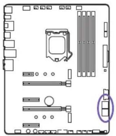
- For a single PCIe x16, please use PCIEX16_1.
- When adding or removing expansion cards, always turn off the power supply and unplug the power supply power cable from the power outlet. Read the expansion card's documentation to check for any necessary additional hardware or software changes.
3.7 SATA CONNECTORS
Introduction
These connectors are SATA 6Gb/s interface ports. Each connector can connect to one SATA device. No ports utilize the same bandwidth with any M.2.
natural_image
Diagram of a computer motherboard layout showing slots, connectors, and a highlighted component (no text or labels)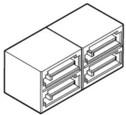
natural_image
Isometric line drawing of a two-cell electrical connector housing (no text or symbols)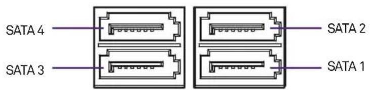
text_image
SATA 4 SATA 3 SATA 2 SATA 1
Note
- Please do not fold the SATA cable at a 90-degree angle. Data loss may result during transmission otherwise.
- SATA cables have identical plugs on either side of the cable. However, it is recommended that the flat connector be connected to the motherboard for space saving purposes.
3.8 M.2 SLOTS
Introduction
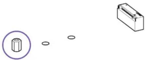
There are two M.2 slots on the N7 motherboard. You will need to remove the steel cover pieces prior to installation. The M.2 slots supports form factors up to type 2280.
natural_image
Diagram of a computer motherboard showing CPU socket, RAM slots, and indicator lights (no text or labels)Installation
- Remove the M.2 slot cover.
text_image
1. 2. 3.- Confirm the standoff is at the required position and if necessary, move the standoff.
natural_image
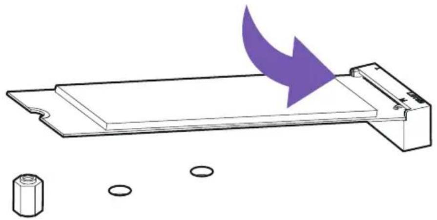
Diagram showing a hexagonal nut with a purple circle and three small circular holes, next to a rectangular block (no text or symbols)- Insert your M.2 drive into the M.2 slot at an angle.
natural_image
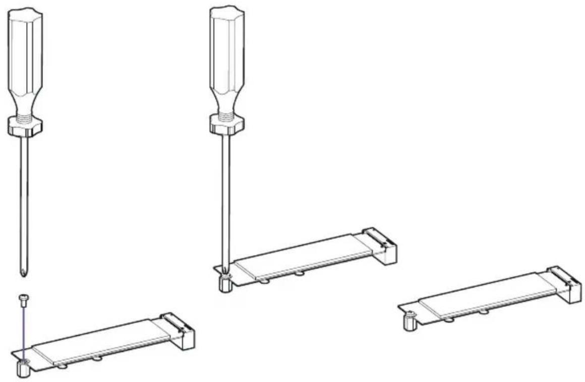
Diagram of a battery tray with an arrow indicating direction, and a separate cylindrical component below (no text or symbols)- Secure the M.2 drive using the M.2 screw onto the standoff and tighten.
natural_image
Technical line drawings of screwdriver and bracket components (no text or symbols)
Note
- If you have installed an M.2 drive, leave the steel cover off to ensure optimal cooling for your M.2 drives. The NZXT logo cover piece has a removable M.2 cover, press on the lock and slide to release.
- Intel® RST only supports PCIe M.2 SSD with UEFI ROM.
- Intel® Optane™ Memory Ready for all M.2 slots.
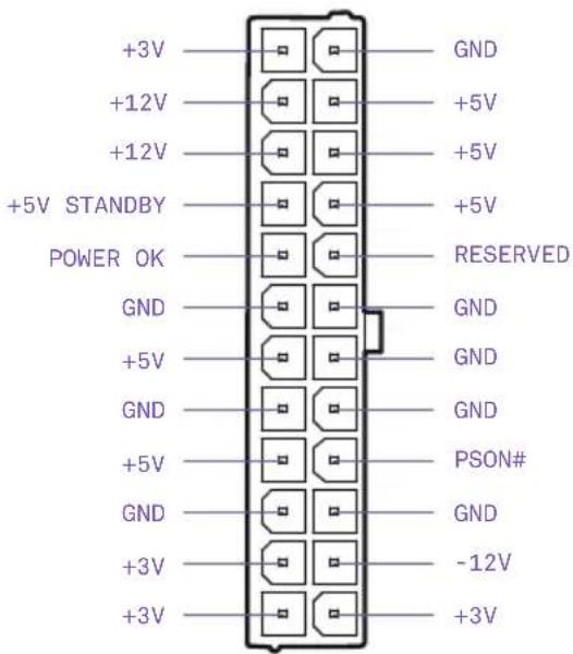
3.9 POWER CONNECTORS
Introduction
These connectors connect to an ATX power supply.
natural_image
Top-down view of a computer motherboard showing CPU socket, RAM slots, and memory card (no text or labels)24-pin ATX_POWER

You may need to remove the mosfet cover piece before connecting the 8-pin CPU power.

Note
- Make sure that all the power cables are securely connected to a proper ATX power supply to ensure stable operation of the motherboard.
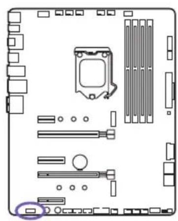
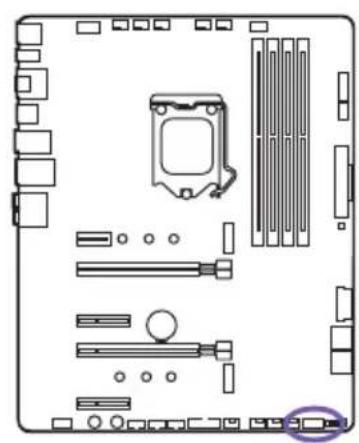
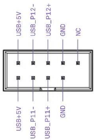
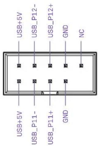
3.10 USB 2.0 & 3.0 CONNECTORS
Introduction
These connectors allow you to connect to the front panel USB ports or devices requiring internal USB ports.
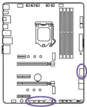
natural_image
Diagram of a computer motherboard showing CPU socket, RAM slots, and memory drive components (no text or labels)USB 3.0USB 2.0

text_image
USB+5V USB_P12- USB_P12+ GND NC USB+5V USB_P11- USB_P11+ GND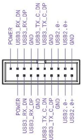
text_image
POWER USB3_RX_DN USB3_RX_DP GND USB3_TX_C_DN USB3_TX_C_DP GND USB2.0- USB2.0+ GND POWER USB3_RX_DN USB3_RX_DP GND USB3_TX_C_DN USB3_TX_C_DP GND USB3_TX_C_DP GND USB2.0- USB2.0+3.11 FRONT PANEL AUDIO CONNECTOR
Introduction
This connector connects to the front panel audio on the case.
natural_image
Top-down schematic of a computer motherboard showing CPU socket, RAM slots, and drive components (no text or labels)
text_image
FRONT L SENSE_SEND FRONT R MIC R MIC L SENSE2_RETURN SENSE1_RETURN PRESENCE# GND3.12 FRONT PANEL CONNECTOR
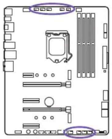
Introduction
These connectors connect to the switches and indicator LEDs on the case.
natural_image
Diagram of a computer motherboard layout showing slots, connectors, and memory components (no text or labels)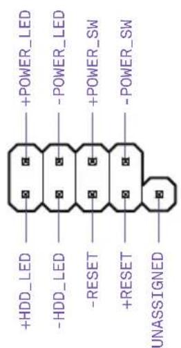
text_image
+HDD_LED -HDD_LED -RESET +RESET UNASSIGNED +POWER_LED -POWER_LED +POWER_SW -POWER_SW
Important
Please check the polarity of the pins to ensure your LEDs work properly.
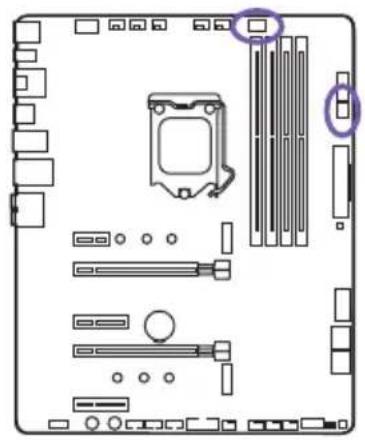
3.13 FAN CONNECTORS
Introduction
The CPU_FAN, AIO_PUMP, W_PUMP and the six SYS_FAN connectors support both PWM(Pulse Width Modulation) and voltage modes. The fan speeds can be adjusted within the BIOS or CAM.
natural_image
Top-down view of a computer motherboard showing CPU socket, RAM slots, and hardware components (no text or labels)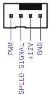
text_image
PWM SPEED SIGNAL +12V GND
Important
CAM is required to control the fans within Windows.
3.14 LED CONNECTORS
Introduction
There are two LED ports located here and is used to attach to HUE+ LED strips or the Aer RGB LED fans. Each port supports up to 4 LED strips or 5 Aer RGB fans.
natural_image
Top-down view of a computer motherboard showing CPU socket, RAM slots, and drive bays (no text or labels)
text_image
5V DATA IN GND DETECT
Important
- Use the connection cable included in the HUE+ Extension Kit or Aer RGB.
- CAM is required to control the lighting within Windows.
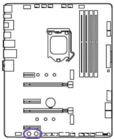
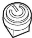
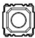
3.15 BUTTONS & SWITCHES
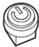
Introduction
The power and reset button allows you to power on or reset the motherboard without connecting to a switch which is useful when testing.
natural_image
Top-down schematic of a computer motherboard showing CPU socket, RAM slots, and memory card (no text or labels)
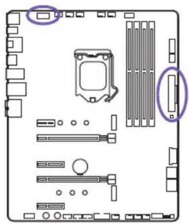
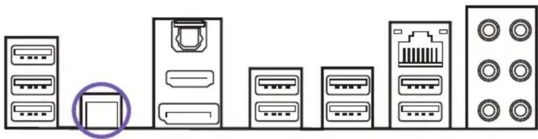
Clear CMOS Button
The Clear CMOS button located on the rear I/O can be used to revert BIOS settings to default. To clear CMOS, turn off the power and remove the AC power to the power supply. Allow 30 seconds to ensure no standby power exists. Press and hold the Clear CMOS button for 3 seconds.
natural_image
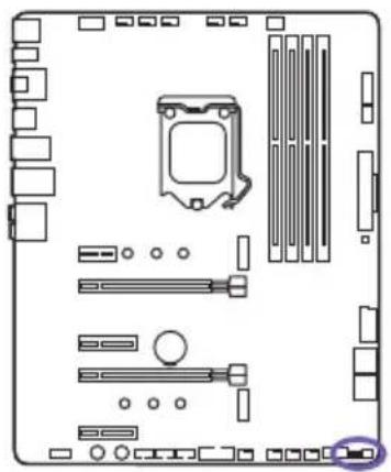
Diagram showing various electronic devices including server racks, connectors, and a central device with a purple circle highlighting a specific component (no text or labels present)Dual BIOS Switch & ROM Back Up
Located here is the "Dual BIOS switch" and "ROM_BACKUP" button. The N7 has two built-in BIOS ROMs with the Primary set to A. If the Primary fails, you can switch to B to load the Secondary BIOS ROM and revert the Primary BIOS back to factory (see BIOS Back Up).
natural_image
Diagram of a computer motherboard layout showing slots, RAM slots, and a highlighted CPU socket (no text or labels)

BIOS Back Up
When the Primary BIOS fails, perform the following steps to revert to the factory BIOS.
- Turn off the power and remove the AC power to the power supply. Allow 30 seconds to ensure no standby power exists.
- Flip the “Dual BIOS switch” to B and reconnect power to the power supply. The ROM LED will glow indicating the Secondary BIOS has been loaded.
- Boot into BIOS and navigate to Power Management under the Advanced Menu. Disable EUP Function then proceed to save changes and reboot.
- Power off the PC and press and hold the "ROM_BACKUP" button for 5 seconds.
- The ROM LED will blink indicating it is currently loading the Secondary BIOS ROM into the Primary BIOS ROM.
- Back up is finished if the ROM LED remains on.
- Turn off the power and remove the AC power to the PC. Allow 30 seconds to ensure no standby power exists.
- Flip the switch to side A to load the Primary BIOS.
natural_image
Technical line drawing of a server rack with internal components and ventilation ducts (no text or symbols)CONTENIDO
Intel® Z370 Express Chipset
- 1 tipo M.2 2242/2260/2280 (PCIe 3.0 x4 y modo SATA)
- 1 tipo M.2 2242/2260/2280 (solo en modo PCIe 3.0 x4)
• 4 puertos SATA de 6 Gbps
Intel® I219-V Gigabit
Audio
Codificador Realtek® ALC1220
natural_image
Technical line drawing of a computer motherboard with visible slots, connectors, and ventilation grilles (no text or labels)Vista detallada
natural_image
Exploded view diagram of a computer motherboard showing internal components and connections (no text or labels)Z370 ATX MOTHERBOARD
3.4 ZÓCALO DE CPU
Introducción
natural_image
Diagram of a computer motherboard showing CPU socket, RAM slots, and hardware components (no text or labels)Instalación

text_image
Technical diagram showing three stages of a device assembly with purple arrows indicating motion and alignment, including a magnified inset view.natural_image
Technical illustration of a device's internal components, showing two views with purple arrows indicating assembly or disassembly (no text or symbols present)natural_image
Technical line drawing of two electronic components with a purple arrow indicating rotation (no text or symbols)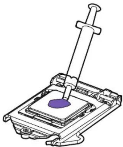
natural_image
Technical line drawing of a mechanical assembly with a purple component inserted into a housing (no text or symbols)text_image
Technical diagram showing a computer motherboard with labeled ports and an exploded view highlighting the internal structure.Instalación
natural_image
Diagram showing three views of a RAM module with arrows indicating assembly or adjustment (no text or symbols present)natural_image
Diagram of a mechanical device with two ports and three connectors, showing alignment or assembly (no text or symbols)natural_image
Technical line drawing of a mechanical device with no visible text or symbolsnatural_image
Technical line drawing of a mechanical device with two purple circular annotations highlighting features (no text or symbols present)natural_image
Top-down schematic of a computer motherboard showing CPU socket, RAM slots, and memory card (no text or labels)
natural_image
Isometric line drawing of a two-chamber electrical connector housing (no text or symbols)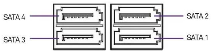
text_image
SATA 4 SATA 3 SATA 2 SATA 1
Nota
natural_image
Diagram of a computer motherboard showing CPU socket, RAM slots, and drive bays (no text or labels)Instalación
natural_image
Diagram showing a hexagonal nut with a purple circle and three small circular holes, next to a rectangular block (no text or symbols)natural_image
Diagram of a battery tray with an arrow indicating direction, and a separate cylindrical component below (no text or symbols)natural_image
Technical line drawings of screwdriver and bracket components (no text or symbols)
Nota
natural_image
Top-down view of a computer motherboard showing CPU socket, RAM slots, and memory card (no text or labels)ATX_POWER de 24 patillas

natural_image
Diagram of a computer motherboard showing CPU socket, RAM slots, and memory drive components (no text or labels)USB 3.0USB 2.0
text_image
USB+5V USB_P12- USB_P12+ GND NC USB+5V USB_P11- USB_P11+ GND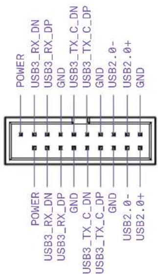
text_image
POWER USB3_RX_DN USB3_RX_DP GND USB3_TX_C_DN USB3_TX_C_DP GND USB2.0- USB2.0+ GND POWER USB3_RX_DN USB3_RX_DP GND USB3_TX_C_DN USB3_TX_C_DP GND USB3_TX_C_DP GND USB2.0- USB2.0+3.11 CONECTOR DE AUDIO DEL PANEL FRONTAL
Introducción
natural_image
Top-down schematic of a computer motherboard showing CPU socket, RAM slots, and memory card (no text or labels)
text_image
FRONT L SENSE_SEND FRONT R MIC R MIC L SENSE2_RETURN SENSE1_RETURN PRESENCE# GND3.12 CONECTOR DEL PANEL FRONTAL
Introducción
natural_image
Diagram of a computer motherboard layout showing CPU socket, RAM slots, and memory components (no text or labels)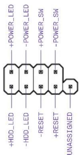
text_image
+HDD_LED -HDD_LED -RESET +RESET UNASSIGNED +POWER_LED -POWER_LED +POWER_SW -POWER_SW
Importante
natural_image
Top-down view of a computer motherboard showing CPU socket, RAM slots, and connectors (no text or labels)
text_image
PWM SPEED SIGNAL +12V GND
Nota
natural_image
Top-down view of a computer motherboard showing CPU socket, RAM slots, and drive bays (no text or labels)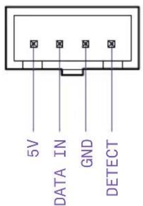
text_image
5V DATA IN GND DETECT
Nota
natural_image
Top-down schematic of a computer motherboard showing CPU socket, RAM slots, and memory card (no text or labels)
natural_image
Diagram showing various server and port icons arranged in rows, with one device highlighted (no text or labels present)natural_image
Diagram of a computer motherboard layout showing slots, RAM slots, and a highlighted CPU socket (no text or labels)
natural_image
Technical line drawing of a server rack with labeled components (no readable text or symbols)TABLE DES MATIERES
1 PREFACE.... 1
2 INFORMATIONS SUR LE PRODUIT
2. INFORMATIONS SUR LE PRODUIT
2.1 CONTENU DE L'EMBALLAGE
Chipset Intel® Z370 Express
- 1 x type M.22242/2260/2280 (mode PCIe 3.0 x4 et SATA)
- 1 x type M.2 2242/2260/2280 (mode PCIe 3.0 x4 uniquement)
• 4 x ports SATA 6 Gbit/s
Prise en charge de RAID 0/1/5/10
Prise en charge de la technologie Intel® Smart Response
Technologie Intel® Rapid Storage
Compatibilité mémoire Intel® Optane
LAN
LAN Intel® I219-V Gigabit
Audio
Codec Realtek® ALC1220
natural_image
Technical line drawing of a computer motherboard showing internal components like CPU socket, RAM slots, and drive bays (no text or labels)Vue éclatée
natural_image
Exploded view diagram of a computer motherboard showing internal components and connections (no text or labels)3.2 PRÉSENTATION DES PORTS
text_image
29 30 23 4 5 RP USB ATR 129 CPU_TAN ATIL_SURP/SYS_TARE/SYTH/SPR/SPR LED2 CLR_CODG BITK HDMI_OP_SPDF USB7_2 USB8_2 USB9_2 USB_LAN BYAR_AUDIO LGA 1151 6 7 8 NZZXT N7 Z370 MODEL: N7 Z370 TERRAGON 2.3 Budget to Cattercrafts PCIEX1_1 PCIEX1_1 PCIEX1_1 PCIEX1_1 PCIEX1_1 PCIEX1_1 PCIEX1_1 PCIEX1_1 PCIEX1_1 PCIEX1_1 PCIEX1_1 PCIEX1_1 PCIEX1_1 PCIEX1_1 PCIEX1_1 PCIEX1_1 PCIEX1_1 PCIEX6_7 FRONT ALOIO POWERRESET USB2_1 USB2_2 USB2_3 JBB3_1 SYS_FANW_PUMP_SYS_FANZ_SYS_FRANKEL ROM_BACKUP_COAL_BIOS 20 19 18 17 16 15 14 13 12 28 27 26 25 24 23 22 21No. Nom description du port
Z370 ATX MOTHERBOARD
3.4 SOCKET POUR PROCESSEUR
Introduction
natural_image
Diagram of a computer motherboard showing CPU socket, RAM slots, and hardware components (no text or labels)Installation

text_image
Technical diagram showing three stages of a device assembly with purple arrows indicating motion and alignment, including a magnified inset view.natural_image
Technical illustration of a device's internal components, showing two views with purple arrows indicating assembly or disassembly (no text or symbols present)natural_image
Technical illustration of a mechanical assembly with two views showing internal components and a needle inserted (no text or symbols)text_image
Technical diagram showing a computer motherboard with labeled ports and a populate indicator for B1 First.Installation
natural_image
Diagram showing three views of a RAM module with internal slots and mounting brackets, no text or symbols presenttext_image
figuration requise.natural_image
Technical line drawing of a mechanical device with no visible text or symbolsnatural_image
Technical line drawing of a mechanical device with two purple circular annotations highlighting features (no text or symbols present)natural_image
Diagram of a computer motherboard layout showing slots, connectors, and a highlighted component (no text or labels)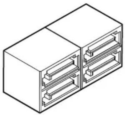
natural_image
Isometric line drawing of a two-port electrical connector housing (no text or symbols)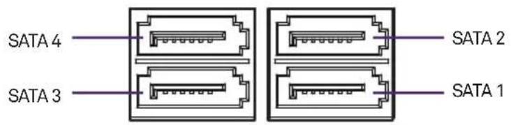
text_image
SATA 4 SATA 3 SATA 2 SATA 1
Remarque
natural_image
Diagram of a computer motherboard showing CPU socket, RAM slots, and indicator lights (no text or labels)Installation
natural_image
Diagram showing a hexagonal nut with a purple circle and three small circular holes, next to a rectangular block (no text or symbols)natural_image
Diagram of a battery holder with a purple arrow indicating flow direction, and a separate cylindrical component below (no text or symbols)natural_image
Technical line drawings of screwdriver and bracket components (no text or symbols)
Remarque
natural_image
Diagram of a computer motherboard showing CPU socket, RAM slots, and memory compartment (no text or labels)natural_image
Diagram of a computer motherboard showing CPU socket, RAM slots, and memory drive components (no text or labels)USB 3.0USB 2.0

text_image
USB+5V USB_P12- USB_P12+ GND NC USB+5V USB_P11- USB_P11+ GND
text_image
POWER USB3_RX_DN USB3_RX_DP GND USB3_TX_C_DN USB3_TX_C_DP GND USB2.0- USB2.0+ GND POWER USB3_RX_DN USB3_RX_DP GND USB3_TX_C_DN USB3_TX_C_DP GND USB3_TX_C_DP GND USB2.0- USB2.0+3.11 CONNECTEUR AUDIO POUR PANNEAU AVANT
Introduction
natural_image
Top-down schematic of a computer motherboard showing CPU socket, RAM slots, and memory card (no text or labels)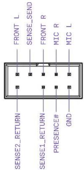
text_image
FRONT L SENSE_SEND FRONT R MIC R MIC L SENSE2_RETURN SENSE1_RETURN PRESENCE# GND3.12 CONNECTEUR PANNEAU AVANT
Introduction
natural_image
Top-down schematic of a computer motherboard showing CPU socket, RAM slots, and memory components (no text or labels)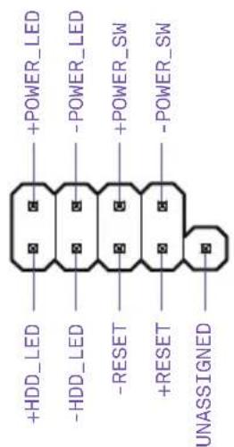
text_image
+HDD_LED -HDD_LED -RESET +RESET UNASSIGNED +POWER_LED -POWER_LED +POWER_SW -POWER_SW
Important
natural_image
Top-down view of a computer motherboard showing CPU socket, RAM slots, and connectors (no text or labels)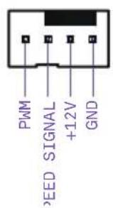
text_image
PWM SPEED SIGNAL +12V GND
Remarque
natural_image
Top-down view of a computer motherboard showing CPU socket, RAM slots, and drive bays (no text or labels)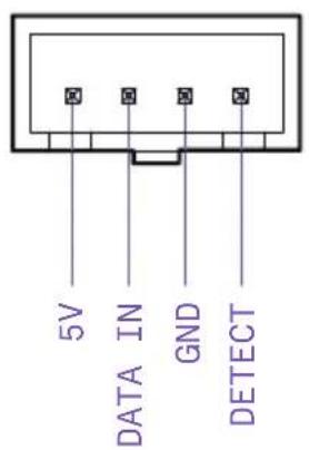
text_image
5V DATA IN GND DETECT
Remarque
natural_image
Top-down schematic of a computer motherboard showing CPU socket, RAM slots, and memory drive components (no text or labels)

Bouton Clear CMOS
natural_image
Diagram showing various server and port icons arranged in rows, with one device highlighted (no text or labels present)natural_image
Diagram of a computer motherboard layout showing slots, RAM slots, and a highlighted CPU socket (no text or labels)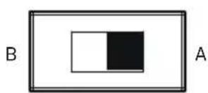

Sauvegarde BIOS
natural_image
Technical line drawing of a server rack with internal components and ventilation slots (no text or symbols)INHALT
1 VORWORT.... 1
2 PRODUKTINFORMATIONEN
2. PRODUKTINFORMATIONEN
2.1 LIEFERUMFANG
4x DIMM, Max. 64 GB, DDR4
natural_image
Technical line drawing of a computer motherboard showing internal components like CPU socket, RAM slots, and drive bays (no text or labels)Explosionszeichnung

natural_image
Exploded view diagram of a computer motherboard showing internal components and connections (no text or labels)Z370 ATX MOTHERBOARD
3.4 CPU-SOCKETEL
natural_image
Diagram of a computer motherboard showing CPU socket, RAM slots, and hardware components (no text or labels)nstallation
text_image
Technical diagram showing three stages of a device assembly with purple arrows indicating motion and alignment, including a magnified inset view.natural_image
Technical illustration of a device's internal components, showing two views with purple arrows indicating assembly or disassembly (no text or symbols present)natural_image
Technical illustration of a mechanical assembly with two views: one showing a component being inserted, the other showing a post mounted component with a purple sphere (no text or symbols)natural_image
Diagram showing three views of a RAM module with internal slots and mounting brackets, no text or symbols present.natural_image
Diagram of a mechanical device with two ports and three rows of connectors, showing directional arrows (no text or symbols)natural_image
Technical line drawing of a mechanical device with no visible text or symbolsnatural_image
Technical line drawing of a mechanical device with two purple circular annotations highlighting features (no text or symbols present)natural_image
Top-down schematic of a computer motherboard showing CPU socket, RAM slots, and memory card (no text or labels)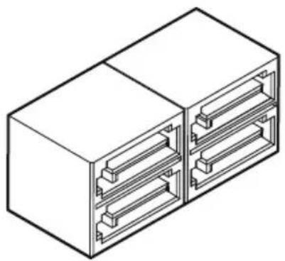
natural_image
Isometric line drawing of a two-port electrical connector housing (no text or symbols)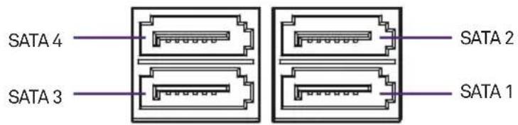
text_image
SATA 4 SATA 3 SATA 2 SATA 1
Hinweis
natural_image
Diagram of a computer motherboard showing CPU socket, RAM slots, and indicator lights (no text or labels)Installation
natural_image
Diagram showing a hexagonal nut with a purple circle and three small circular holes, next to a rectangular block (no text or symbols)natural_image
Diagram of a battery holder with a purple arrow indicating flow direction, and a separate cylindrical component below (no text or symbols)natural_image
Technical line drawings of screwdriver and bracket components (no text or symbols)
Hinweis
natural_image
Diagram of a computer motherboard showing CPU socket, RAM slots, and memory card (no text or labels)24-poliger ATX_POWER
natural_image
Diagram of a computer motherboard showing CPU socket, RAM slots, and memory drive components (no text or labels)USB 3.0USB 2.0
text_image
USB+5V USB_P12- USB_P12+ GND NC USB+5V USB_P11- USB_P11+ GND
text_image
POWER USB3_RX_DN USB3_RX_DP GND USB3_TX_C_DN USB3_TX_C_DP GND USB2.0- USB2.0+ GND POWER USB3_RX_DN USB3_RX_DP GND USB3_TX_C_DN USB3_TX_C_DP GND USB3_TX_C_DP GND USB2.0- USB2.0+natural_image
Top-down schematic of a computer motherboard showing CPU socket, RAM slots, and memory card (no text or labels)
text_image
FRONT L SENSE_SEND FRONT R MIC R MIC L SENSE2_RETURN SENSE1_RETURN PRESENCE# GNDnatural_image
Diagram of a computer motherboard layout showing CPU socket, RAM slots, and memory components (no text or labels)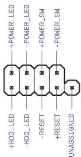
text_image
+HDD_LED -HDD_LED -RESET +RESET UNASSIGNED +POWER_LED -POWER_LED +POWER_SW -POWER_SW
Wichtig
natural_image
Top-down view of a computer motherboard showing CPU socket, RAM slots, and connectors (no text or labels)
text_image
PWM SPEED SIGNAL +12V GND
Hinweis
natural_image
Diagram of a computer motherboard layout showing CPU socket, RAM slots, and memory card (no text or labels)
text_image
5V DATA IN GND DETECT
Hinweis
natural_image
Top-down schematic of a computer motherboard showing CPU socket, RAM slots, and memory card (no text or labels)

Clear CMOS-Schalter
natural_image
Diagram showing various server and port equipment icons arranged in rows (no text or labels)natural_image
Diagram of a computer motherboard layout showing slots, RAM slots, and a highlighted CPU socket (no text or labels)

BIOS Backup
NZXT motherboards carry a 3-year warranty from the date of purchase for parts and labor. Any replacement product will be warranted for the remainder of the warranty period or thirty days, whichever is longer. Proof of purchase is required for warranty service.
Who is Protected
The Warranty covers only NZXT products purchased by the original consumer from authorized NZXT retailers.
What Is Covered
Please note that our warranty is not an unconditional guarantee. If the product, in NZXT's opinion, malfunctions within the warranty period, NZXT will at its discretion repair or replace the product that is equal or greater in value depending on supply. The warranty does not cover any NZXT product that was damaged due to accident, misuse, abuse, improper installation, usage not in accordance with product specifications and instructions, natural or personal disaster, or unauthorized alterations, repairs or modifications.
Our warranty does not cover the following:
Any product or serial number/warranty sticker modification applied without permission from NZXT. Any damage that is not a manufacturing defect. Damage, deterioration or malfunction resulting from accident, abuse, misuse, neglect, fire, water, lightning, or other acts of nature, unauthorized product modification or failure to follow instructions included with the product. Repair or attempted repair by anyone not authorized by NZXT. Shipping or transport damage (claims must be made with the carrier) Normal wear and tear. NZXT does not warrant that this product will meet your requirements. It is your responsibility to determine the suitability of this product for your purpose. Removal or installation charges. Shipping charges. Any incidental charges.
Exclusion Of Damages (Disclaimer)
NZXT's sole obligation and liability under this warranty is limited to the repair or replacement of a defective product at our option. NZXT shall not, in any event, be liable for any incidental or consequential damage, including but not limited to damages resulting from interruption of service and loss of data, business, or for liability in tort relating to this product or resulting from its use or possession.
Limitations Of Implied Warranties
There are no other warranties, expressed or implied, including but not limited to those of merchantability or fitness for a particular purpose. The duration of implied warranties is limited to the warranty length specified in Paragraph I.
Local Law And Your Warranty
This warranty gives you specific legal rights. You may also have other rights granted under local law. These rights may vary.
To Obtain Technical Support.
If you have already referenced your product owner's manual and still need help, please visit support.nzxt.com for details and contact information.
For Warranty Service.
In the event that warranty repair or replacement is necessary, NZXT will request and you must provide proof of purchase (store receipt or invoice) in order to receive warranty service.
For North American Customers:
Within the first 60 days after purchase, please return your product (or for power supplies installed within our enclosures, just the failed power supply) to your dealer or reseller for a replacement. If the product is still within warranty and you can no longer return it to your dealer, please contact NZXT Customer Support (support.nzxt.com) for assistance and instructions. NZXT will not accept returns without prior approval and an RMA number.
In Europe:
Within the first year after purchase, please return your product (or for power supplies installed within our enclosures, just the failed power supply) to your dealer or reseller for a replacement. If the product is still within warranty and you can no longer return it to your dealer, please contact NZXT Customer Support for assistance and instructions. NZXT will not accept returns without prior approval.
Global Customers (Outside North America and Europe):
If your product needs to be returned or repair within the warranty period, please do so through the retailer or distributor from whom you purchased the product. If you can no longer return the product to your dealer, please contact NZXT Customer Support for assistance. Please note, proof of purchase from an authorized NZXT retailer is required for ALL warranty servicing.
Warranty terms for all NZXT products sold to Australia.
Our goods come with guarantees that cannot be excluded under the Australian Consumer Law. You are entitled to a replacement or refund for a major failure and or compensation for any other reasonably foreseeable loss or damage. You are also entitled to have the goods repaired or replaced if the goods fail to be of acceptable quality and the failure does not amount to a major failure' (NZXT Corporation, 13164 E. Temple Ave., City of Industry, CA 91746, USA TEL: +1-800-228-9395) Please contact the shop you purchased from to receive prompt service. If the dealer refuses to offer the service, please contact us at directly at support.nzxt.com
N7
- Visit support.nzxt.com for information on warranty coverage and service
- Visite el sitio Web support.nzxt.com para obtener información sobre la cobertura y el servicio de la garantía.
- Visitez support.nzxt.com pour les informations de la couverture de la garantie et du service.
- Informationen zu Geltungsbereich und Service der Garantie finden Sie unter support.nzxt.com
- Visitare il sito support.nzxt.com per informazioni sulla copertura e sul servizio della garanzia.
- Visite support.nzxt.com para obter informações sobre a cobertura da garantia e assistência
- Подробную информацию об условиях гарантийного обслуживания см. на веб-сайте support.nzxt.com
-보증 범위와 서비스에 대한 자세한 내용은 support.nzxt.com을 참조하십시오 - 保証範囲およびサービスに関する情報については、support.nzxt.com にアクセスしてください。
- 请造访 support.nzxt.com 了解保修范围和服务的信息
• 請訪問 support.nzxt.com 了解產品保固範圍和更多服務訊息
5. SUPPORT AND SERVICE
Support and service
If you have any questions or problems with the NZXT product you purchased, please don't hesitate to contact us using our support system. support.nzxt.com. Please include a detailed explanation of your problem and your proof of purchase. For comments and suggestions, you can e-mail our design team, designer@nzxt.com. Lastly we would like to thank you for your support by purchasing this product. For more information about NZXT, please visit us online. NZXT Website: nzxt.com
Soporte y servicio
For more building tips and information, visit: blog.nzxt.com
6. REGULARTORY NOTICES
1. FCC Compliance Statement
This equipment has been tested and found to comply with the limits for a Class B digital device, pursuant to Part 15 of the FCC Rules. These limits are designed to provide reasonable protection against harmful interference in a residential installation. This equipment generates, uses, and can radiate radio frequency energy and, if not installed and used in accordance with the instructions, may cause harmful interference to radio communications. However, there is no guarantee that interference will not occur in a particular installation. If this equipment does cause harmful interference to radio or television reception, which can be determined by turning the equipment off and on, the user is encouraged to try to correct the interference by one or more of the following measures:
- Reorient or relocate the receiving antenna
- Increase the separation between the equipment and the receiver
- Connect the equipment onto an outlet on a circuit different from that to which the receiver is connected
- Consult the dealer or an experienced radio/TV technician for help
Shielded interconnect cables and a shielded AC power cable must be employed with this equipment to ensure compliance with the pertinent RF emission limits governing this device. Changes or modifications not expressly approved by the system's manufacturer could void the user's authority to operate the equipment.
2. Declaration of Conformity
I. This device complies with part 15 of the FCC rules. Operation is subject to the following conditions:
• This device may not cause harmful interference
- This device must accept any interference received, including interference that may cause undesired operation.
II. CE Conformity
NZXT Inc, declares that this device is in compliance with the essential safety requirements and other relevant provisions set out in the European Directive.
III. This device is in conformity with the following EC/EMC directives:
• EN 55022 Limits and methods of measurement of radio disturbance characteristics of information technology equipment.
• EN 61000-3-2 Disturbance in supply systems caused
- EN 61000-3-3 Disturbance in supply systems caused by household appliances and similar electrical equipment “Voltage fluctuations”
• EN 55024 Information technology equipment-immunity characteristics – Limits and methods of measurement
• EN 60950 Safety for information technology equipment including electrical business equipment
IV. Canadian Department of Communications
This class B digital apparatus meets all requirements of the Canadian Interference-causing Equipment Regulations.
Batteries, battery packs, and accumulators should not be disposed of as unsorted household waste. Please use the public collection system to return, recycle, or treat them in compliance with the local regulations.
Taiwan

For better environmental protection, waste batteries should be collected separately for recycling or special disposal.
California, USA

The button cell battery may contain perchlorate material and requires special handling when recycled or disposed of in California. For further information please visit:
http://www.dtsc.ca.gov/hazardouswaste/perchlorate
Caution
There is a risk of explosion, if battery is incorrectly replaced. Replace with the same or equivalent type recommended by the manufacturer.
8. WEEE (WASTE ELECTRICAL AND ELECTRONIC EQUIPMENT) STATEMENT
English
To protect the global environment and as an environmentalist, NZXT must remind you that...
Under the European (“EU”) Directive on Waste Electrical and Electronic Equipment, Directive 2012/19/EU, effective February 14, 2014, products of “electrical and electronic equipment” cannot be discarded as municipal wastes, and manufacturers of covered electronics must take back such products at the end of their useful life. NZXT will comply with the product take back requirements at the end-of-life of NZXT products that are sold within the EU. You can return these products to local collection points.