
FU8403 - Alarm system ABUS - Free user manual and instructions
Find the device manual for free FU8403 ABUS in PDF.
| Product type | Wireless display for alarm system |
| Brand | ABUS |
| Model | FU8403 |
| Dimensions (W x H x D) | 135 x 220 x 45 mm |
| Weight | 516 g |
| Power supply | 12 V power supply unit (included) |
| Radio frequency | 868.6625 MHz / FM |
| Number of zones | 16, individually programmable |
| Display | 16 status LEDs (red/green) + Power LED (green) and Error LED (red) |
| Visual indicators | Window open/closed, FTS 96E locking, supervision fault, low battery, radio interference |
| Programming | Detector learning via SELECT, SET, ESC buttons |
| Deletion | Individual deletion or full reset (submenu LED 16) |
| Supervision | Detector monitoring: alert if no signal for ~15 minutes |
| Mounting | Wall mounting, with 3 screws and 3 wall plugs included; 1.50 m power cable |
| Environment | Indoor use, temperature 0 °C to +50 °C, max. humidity 90% non-condensing |
| Environmental class | I |
| Package contents | Wireless display, 12 V power supply unit, 3 blank DIN A5 identification cards, 3 printable cards, mounting hardware |
| Compatibility | ABUS wireless detectors (FTS 96E, wireless opening detector, etc.) |
| Main functions | Display of window/door status, LED signalling, programming of up to 16 detectors |
| Care and cleaning | Clean with a soft dry cloth; do not use chemical or abrasive products |
| Safety | Secure wall mounting; avoid inserting metal objects; use only the supplied power supply unit |
| Spare parts and repairability | Available parts: power supply unit (ref. to be verified) and identification cards (downloadable). No user repairs; contact ABUS customer service. |
Frequently Asked Questions - FU8403 ABUS
User questions about FU8403 ABUS
0 question about this device. Answer the ones you know or ask your own.
Ask a new question about this device
Download the instructions for your Alarm system in PDF format for free! Find your manual FU8403 - ABUS and take your electronic device back in hand. On this page are published all the documents necessary for the use of your device. FU8403 by ABUS.
USER MANUAL FU8403 ABUS
Radio-Controlled Display
[UK] Assembly and Operating Instructions 9
Afficheur sans fil
UK Installation and operating instructions for ABUS radio controlled display module
These instructions are subdivided as follows:
I. General information
II. Safety instructions
III. Applications
IV. Contents of the package
V. Signalling concept
VI. Teaching the detectors
VII. Labelling the inlay
VIII. Installation
IX. Technical data
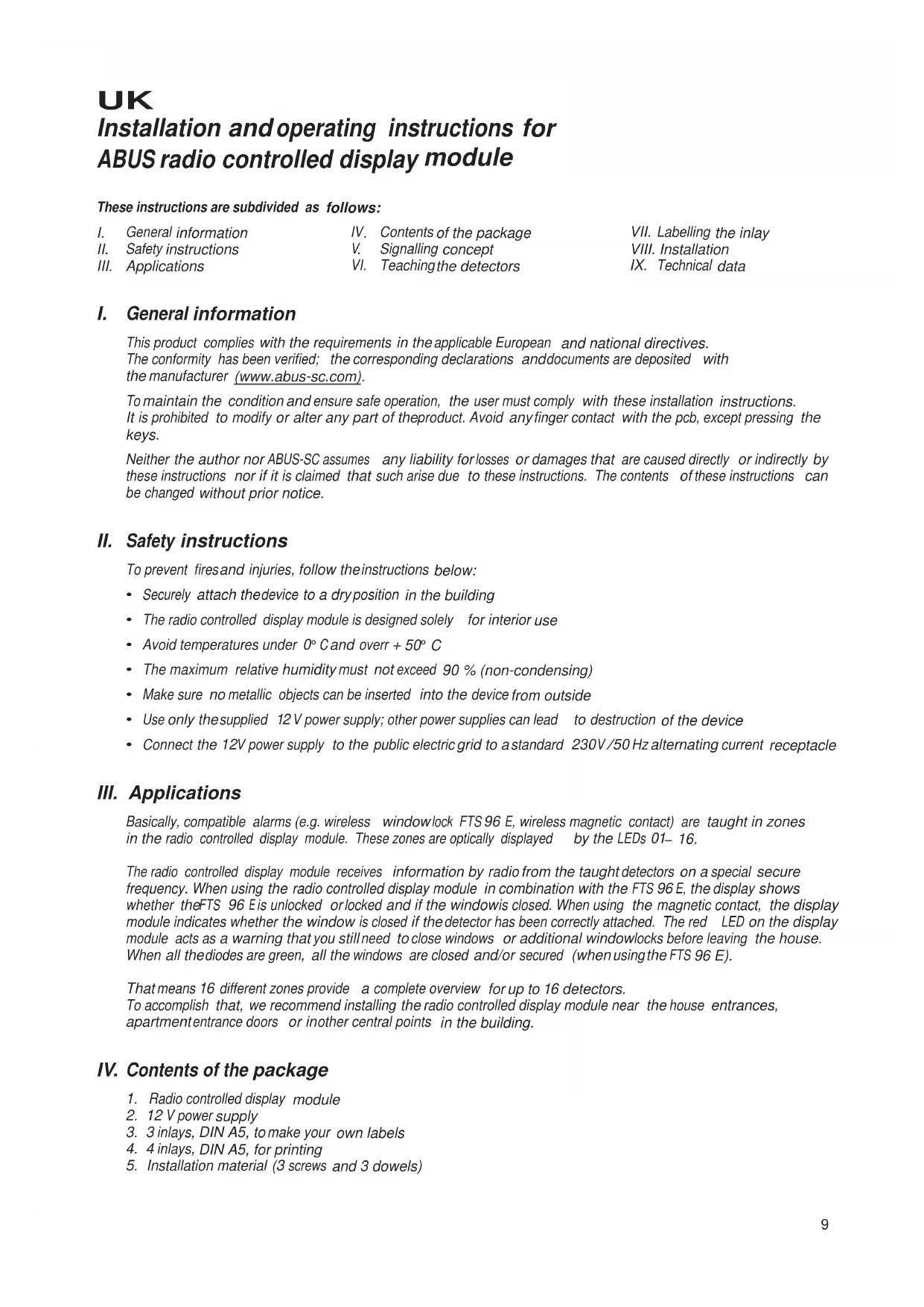
I. General information
This product complies with the requirements in the applicable European and national directives. The conformity has been verified; the corresponding declarations and documents are deposited with the manufacturer (www.abus-sc.com).
To maintain the condition and ensure safe operation, the user must comply with these installation instructions. It is prohibited to modify or alter any part of the product. Avoid any finger contact with the pcb, except pressing the keys.
Neither the author nor ABUS-SC assumes any liability for losses or damages that are caused directly or indirectly by these instructions nor if it is claimed that such arise due to these instructions. The contents of these instructions can be changed without prior notice.
II. Safety instructions
To prevent fires and injuries, follow the instructions below:
- Securely attach the device to a dry position in the building
The radio controlled display module is designed solely for interior use - Avoid temperatures under 0^ and overr +50^
The maximum relative humidity must not exceed 90% (non-condensing) - Make sure no metallic objects can be inserted into the device from outside
- Use only the supplied 12 V power supply; other power supplies can lead to destruction of the device
- Connect the 12V power supply to the public electric grid to a standard 230 V/50 Hz alternating current receptacle
III. Applications
Basically, compatible alarms (e.g. wireless windowlock FTS 96 E, wireless magnetic contact) are taught in zones in the radio controlled display module. These zones are optically displayed by the LEDs 01-16.
The radio controlled display module receives information by radio from the taught detectors on a special secure frequency. When using the radio controlled display module in combination with the FTS 96 E, the display shows whether the FTS 96 E is unlocked or locked and if the window is closed. When using the magnetic contact, the display module indicates whether the window is closed if the detector has been correctly attached. The red LED on the display module acts as a warning that you still need to close windows or additional windowlocks before leaving the house. When all the diodes are green, all the windows are closed and/or secured (when using the FTS 96 E).
That means 16 different zones provide a complete overview for up to 16 detectors.
To accomplish that, we recommend installing the radio controlled display module near the house entrances, apartment entrance doors or in other central points in the building.
IV. Contents of the package
- Radio controlled display module
- 12 V power supply
- 3 inlays, DIN A5, to make your own labels
- 4 inlays, DIN A5, for printing
- Installation material (3 screws and 3 dowels)
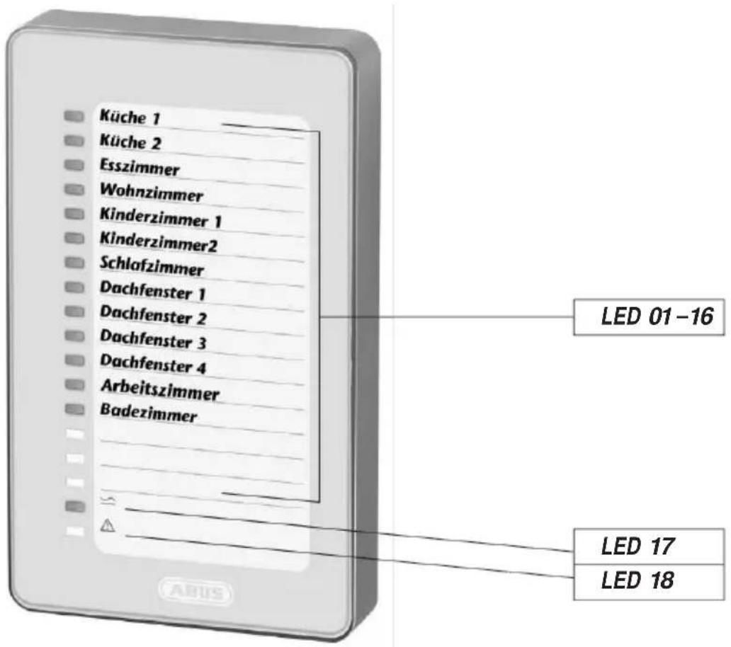
V. Signalling concept
Status LEDs 01- 16:Signalling concept, normal mode
LED off No detector has been taught in the zone or themains voltage has not been applied
- LED flashing red rapidly The status of the zone has not been updated after a mains failure
- LED flashing red slowly Manipulation on the window
- LED shining red Window open or FTS 96 E not locked
LED flashing green Supervision error
LED flashing red/green Lowbatt (low battery condition on the detector)
LED shining green Window closed orFTS 96 E locked
Power LED 17:
LED shining green Mains voltage applied
LED off Mains voltage failed
Error LED 18:
LED shining red Supervision error in one zone (see Point VI. Remarks)
LED flashing red slowly Malfunction
LED flashing red rapidly After a mains failure, no new status was received for all detectors
VI. Teaching the detectors
Remove the bottom from the top of the housing of the radio controlled display module before starting teaching. To do that, unscrew the screws on the bottom and pull off the housing section. Connect the power supply and plug in the jack on the radio controlled display module.
1. General key functions:
- SELECT key (Ta1): Selects menus/values/zones
- SET key (Ta2): Confirms the selection, partially with a delay of 4 seconds (keep pressed)
ESC key (Ta3): Abort, go back one step
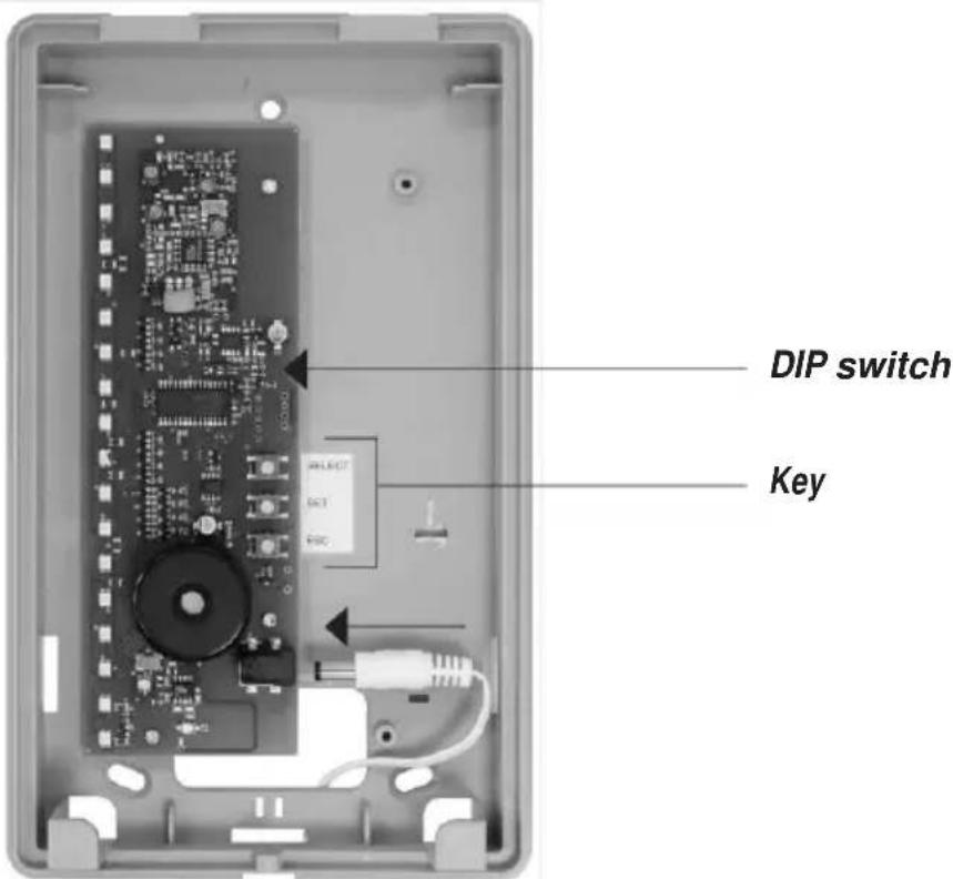
2. DIP switch functions:
DIP 1 Supervision-Monitoring on/off (see Point VI. Remarks)
DIP 2 Malfunction - Monitoring on/off
Both are factory activated (recommended setting).
3. Main menu structure in the radio controlled display module :
- Submenu LED 01: Teach detector
- Submenu LED 02: Delete detector
- Submenu LED 03: Wireless level indicator, detector
- Submenu LED 16: Delete all (factory reset)
Navigation through the menus :
- Select the main menu from the display mode: Press SELECT key 1 once
The submenu LED 01 (teach detector) can beopened with SET key 2 - Selecting the other submenus: With SELECT key 1, jump to the desired submenu; corresponding LED is shining green
- Open the desired submenu with SET key 2
Hint: If you have opened an incorrect menu by mistake, you can exit it using the ESC key. You can always return to the display mode by pressing the ESC key several times.
4. Teaching one detector (Submenu LED 01):
a) Press SELECT key 1 once: Main menu LED 01 is shining green
b) Press SET key 2 once: Submenu LED 01 (teach alarm) opens The LED in the first free zone shines green (if no alarms has been taught, LED 01 is always shining green). Zones already occupied flash red and cannot be selected with the SELECT key. If nomore free zones are available, the LED does not shine
c) The zone you want to teach the detector to can be selected with SELECT key 1
d) SET key 2 opens the zone LED flashes green (ready for learning)
e) Open the tamper contact on FTS 96 E or wireless magnetic contact by removing the cover (to do that, the battery must be fitted to the FTS 96 E or wireless magnetic contact)
f) The radio signal is emitted and the detector is taught to the zone; an acoustic acknowledgement follows
g ) The next free zone is then indicated with the green LED
h) For teaching additional detectors, see Point 4c
i) Exit the menu using ESC key 3
5. Deleting a taught detector (Submenu LED 02):
a) Press SELECT key 1 once: Main menu LED 01 is shining green
b) Press SELECT key 1 once LED 02 shines green
c) Press SET key 2 once: Submenu LED 02 (delete detector) opens The LED in the first assigned zone flashes orange
d) You can select the detector you want to delete with SELECT key 1
e) Press SET key 2(LED flashes more quickly) until the LED goes out detector deleted
f) The next assigned zone then is indicated by the flashing orange LED
g) To delete additional detectors, see Point 5 d)
h) Exit themenu with ESC key 3 or automatically after deleting the lastassigned zone
6. Radio signal strength indicator (Submenu LED 03):
a) Press SELECT key 1 once: Main menu LED 01 is shining green
b) Press the SELECT key 1 twice: LED 03 shines green
c) Press SET key 2 once: Submenu LED 03 (Radio signal strength indicator) opens The LED in the first assigned zone shines green
d) Use SELECT key 1 to select the detector for the lastreceived radio signal level you want to display
e) Press SELECT key 1once: The last received signal strength of the first assigned zone is displayed via the number of shining LEDs starting with LED16; the more LEDs shine, the higher the received radio signal strength. To ensure permanently secure radio reception, at least three LEDs should be shining
f) The next zone can be tested with the SELECT key, etc.
g) Exit themenu using ESC key 3
7. Delete all /Factory reset (Submenu LED 16):
a) Press SELECT key 1 once: Main menu LED 01 is shining green
b) Press SELECT key 1 three times: LED 16 shines green
c) Press SET key 2 once: Submenu LED 16 (factory reset) opens LEDs 01-16 flash red
d) Keep SET key 2 pressed (LEDs flash faster) until all LEDs01 - 16 go out
e) The radio controlled display module automatically returns to the display mode
Notes:
The radio controlled display module automatically returns to the display mode if no activity has occurred for a period of ca. 3 minutes (no keys were pressed and no detector was taught).
If no radio signal has been detected from the respective radio alarm forca. 15 minutes, a supervision error is indicated by the red LED 18 and therespective zone LED flashing green.
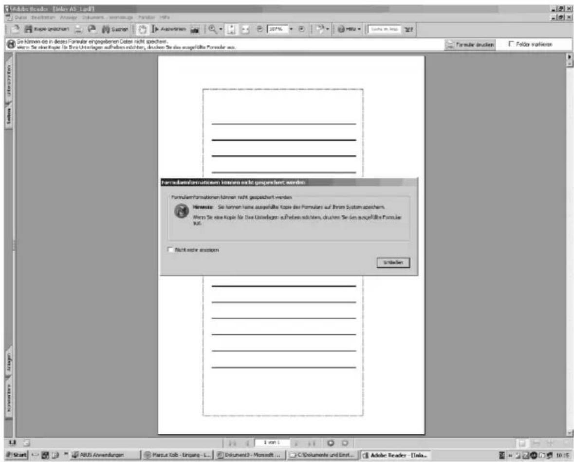
VII. Labelling the inlays
An online tool is available for high quality inlaylabelling using a printer. Alternatively, you can also label manually.
a) Go to Internet page www.abus-sc.de. On the Article FU 8403 you can download the file Druckvorlage_Einleger.pdf
b) After opening the template click on the firstlettering box. The following is displayed (see picture). Click "Close" and startentering your lettering. Use theTAB key to jump to the nextlettering box
c) After completing the lettering, start the "File" menu using the with the sub-item "Print"
d) Adopt these settings:
Page adjustment: None
Automatic rotation and centring
- Select paper source based on the PDF page size
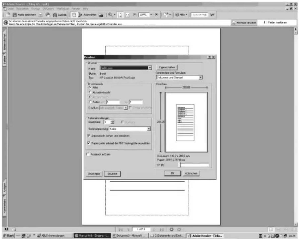
e) Insert the enclosed DIN A5 paper (without lettering) in the printer. Confirm the print job with "OK"
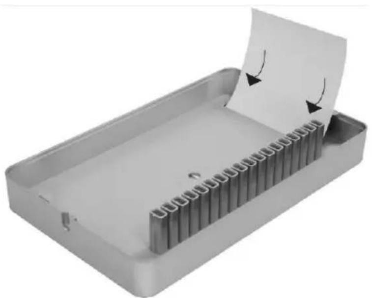
f) Remove printout from printer and cut the template along the marked edge
g) Push the template into the radio controlled display module as shown in the illustration
Note: It is not possible to save the entered data!
VIII. Installation
Hint: Before installing the detector and the radio controlled display module, make sure that there is a reliable radio connection between the intended installation positions.
To ensure permanently secure radio reception, at least three LEDs should be illuminated per alarm (see Point VI. f).
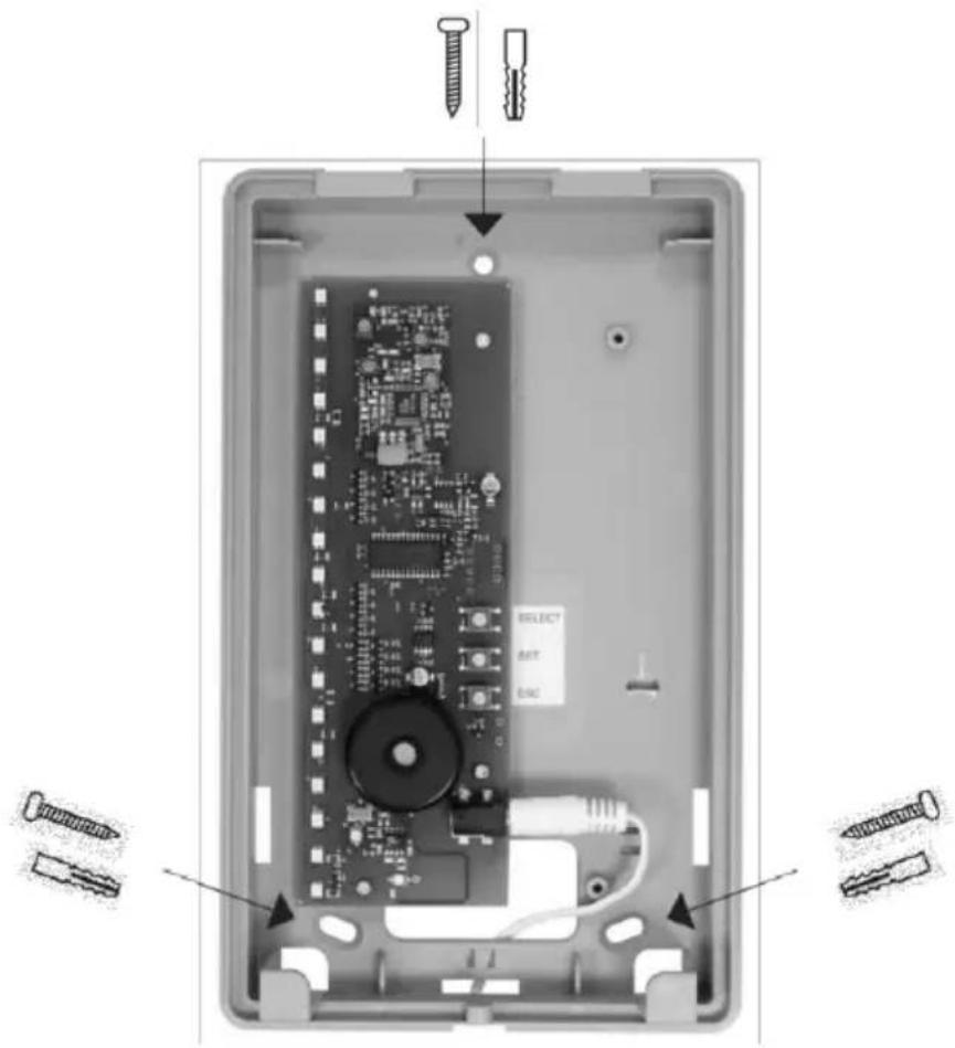
Hold the bottom of theradio controlled display module on thedesired installation position and mark the three drill holes; drill with a 6 mm drill;insert dowel and screw on the bottom part.
Caution: Length of cable on power supply 1.50 metres. A nearby 230 VAC receptacle is required.
After completing the teaching process, put the top part of the radio controlled display module on the installed bottom section and secure to the bottom section with the enclosed screws.
IX. Technical data
Voltage supply: 12V
power supply
Frequency: 868.6625
MHz/F M
Zones: 16,
individuallyprogrammable
Weight: 516 g
Dimensions W × H × D :
135 × 220 × 45 mm
Environmental Class: I
Temperature range: 0^
Cto+50°C
FR
2. DIP-schakelaar-functions:


- Radio-Controlled Display
- Afficheur sans fil
- UK Installation and operating instructions for ABUS radio controlled display module
- General information
- Safety instructions
- Applications
- Contents of the package
- Signalling concept
- Status LEDs 01- 16:Signalling concept, normal mode
- Power LED 17:
- Error LED 18:
- Teaching the detectors
- General key functions:
- DIP switch functions:
- Main menu structure in the radio controlled display module :
- Navigation through the menus :
- Teaching one detector (Submenu LED 01):
- Deleting a taught detector (Submenu LED 02):
- Radio signal strength indicator (Submenu LED 03):
- Delete all /Factory reset (Submenu LED 16):
- Notes:
- Labelling the inlays
- Installation
- Technical data
- FR
- DIP-schakelaar-functions:
Brand : ABUS
Model : FU8403
Category : Alarm system