
DM07 - Multimeter Tacklife - Free user manual and instructions
Find the device manual for free DM07 Tacklife in PDF.
| Product Type | Portable Digital Multimeter |
| Brand | Tacklife |
| Model | DM07 |
| Dimensions | 190 × 89 × 50 mm |
| Weight | ~380 g (with batteries) |
| Power Supply | 4 AA 1.5 V batteries |
| Display | 6000-count LCD screen with backlight and flashlight |
| DC Voltage | 600 mV to 1000 V, accuracy ±(0.5% + 3 digits) |
| AC Voltage (True RMS) | 6 V to 750 V, accuracy ±(0.8% + 3 digits) to ±(1% + 10 digits) |
| DC Current | 60 µA to 10 A, accuracy ±(0.8% + 3 digits) to ±(1.2% + 3 digits) |
| AC Current (True RMS) | 60 µA to 10 A, accuracy ±(1% + 3 digits) to ±(1.5% + 3 digits) |
| Resistance | 600 Ω to 60 MΩ, accuracy ±(0.8% + 3 digits) to ±(1.2% + 30 digits) |
| Capacitance | 6 nF to 100 mF, accuracy ±(4% + 30 digits) to ±(5% + 3 digits) |
| Frequency | 9.999 Hz to 9.999 MHz, accuracy ±(1% + 3 digits) |
| Temperature | -20°C to 1000°C (Type K thermocouple), accuracy ±(1% + 3°C) |
| Diode Test | Yes, up to 3 V, forward current ~1 mA |
| Continuity Test | Yes, audible beep and green LED for resistance <40 Ω |
| NCV Detection | Non-contact voltage detection with light and sound indicators |
| Safety | CAT IV 600 V, CAT III 1000 V, double insulation |
| Protection | Fuses FF600mA/250V (mA) and FF10A/250V (10A) |
| Auto Power Off | After 15 minutes of inactivity |
| Included Accessories | Test leads, Type K thermocouple, user manual |
| Operating Temperature | 0°C to 40°C, relative humidity <80% |
| Maintenance | Clean with a damp cloth, replace batteries and fuses |
Frequently Asked Questions - DM07 Tacklife
User questions about DM07 Tacklife
0 question about this device. Answer the ones you know or ask your own.
Ask a new question about this device
Download the instructions for your Multimeter in PDF format for free! Find your manual DM07 - Tacklife and take your electronic device back in hand. On this page are published all the documents necessary for the use of your device. DM07 by Tacklife.
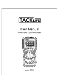
USER MANUAL DM07 Tacklife
This digital multimeter is designed and manufactured in compliance with IEC-61010 safety requirements on electronic measuring instruments and handheld digital multimeters. It is compliant with IEC-61010 requirements pertaining to 600V CAT IV, 1000V CAT. III and requirements on pollution degree 2. Please read carefully this user Manual and pay attention to safety guidelines before operating this meter.
1.1 Safety information
1.1.1 Safety instructions
- Before operating this meter, the operator must observe all standard safety procedures in the two respects below:
A. Safety procedures against electric shock
B. Safety procedures against unintended use
- To ensure your personal safety, please use the test lead that accompanies the meter. Before operating this meter, ensure that the test lead is flawless.
1.1.2 Safety considerations
- When the meter is used in the vicinity of the equipment that produces strong electromagnetic interferences, the readings on the meter will grow unstable and even cause serious errors.
- Don't operate the meter or pen-shaped meter whose appearance is damaged.
- The safety function of the meter will become null if the meter is not properly operated.
- The meter must be operated with great care when working in the vicinity of an exposed conductor or bus line.
- The meter is prohibited from being used in the vicinity of any explosive gas, vapor or dust.
- The measurement must be made with correct input terminals and functions and within the allowable measuring range.
- To prevent the meter from being damaged, the value to be input shall not exceed the extremes allowed by each measuring range.
- When the meter has already been connected to the line being measured, the operator is prohibited from touching the input terminal that is not in service.
- When the voltage measured exceeds 60Vdc or 30Vac (valid value), the operator shall be careful enough to avoid electric shock.
- When making measurements with a test lead, place your fingers behind its protective ring.
- When switching to another measuring range, be sure that test lead has already been removed from the measured circuit.
- For all DC functions, to prevent potential electric shock as a result of incorrect reading, please first use AC functions to check the absence of any AV voltage. Then, select DC voltage measuring range equivalent to or greater than that for AC voltage.
- Before the tests on electric resistance, diode, capacitor or continuity, the operator must cut off the power supply to the circuit to be measured, and discharge all high-voltage capacitors within the circuit to be measured.
- The electric resistance measurement or continuity test cannot be carried out in any live electrical circuit.
- Before the current measurement, the operator must first examine the protective tube of the
meter. Before connecting the meter to the circuit to be measured, the operator must first power off the aforesaid circuit.
- Before repairing TV sets or measuring power switching circuit, the operator must be careful enough to prevent high amplitude voltage impulse from damaging the meter.
- This meter uses 4 × 1.5V AA batteries that must be correctly installed into the battery compartment.
- When + appears, the batteries must be replaced immediately. The low level of a battery will result in incorrect reading on the meter, which is likely to bring electric shock or personal injury to the operator.
- In measurement, category III voltage and category IV voltage shall not exceed 1000V and 600V respectively.
- The meter shall not be in service if its case (or part of its case) is dismantled.
1.1.3 Safety symbol:
The safety symbols that appear on the meter's body and in this Operation Manual:
| A | Warning, an important safety symbol. The operator must consult this Operation Manual before using the meter. Unintended use may lead to the damage to the device or its components. |
| ~ | AC (alternating current) |
| = | DC (direct current) |
| ~ | AC / DC |
| ± | Ground |
| 回 | Double insulation protection |
| - | Fuse |
| CE | Compliant with European Union Directive |
| 4 | High voltage warning |
| CAT. III 1000 V | over-voltage protection |
| CAT. IV 600 V | over-voltage protection |
1.1.4 Maintenance practices for safety
- The operator must first pull out the test lead when the meter's case is opened or the battery cover is dismantled.
- The designated replacement parts must be used at the moment of maintenance.
- The operator must cut off all relevant power supplies before opening the meter. At the same time, the operator must avoid damage to the meter's elements by ensure that he himself doesn't carry any static.
- The meter can only be calibrated, repaired and maintained by professionals.
- When the meter's case is opened, the operator must understand the fact that the presence of some capacitance may promise the dangerous voltages even if the power supply to the meter is cut off.
- The operator should stop using and maintain the meter immediately if any abnormality has been
observed on the meter. The operator must see to it that the meter cannot be in service unless it is proved conforming.
- When the meter is left idle for a long period, the operator shall remove the battery and place it in a place free from high temperature and humidity.
1.2 Input protection measures
- The meter can sustain the maximum input voltage of 1000V (DC) or 750V (AC) at the moment of voltage measurement.
- The meter can sustain the maximum AC voltage of 600V or equivalent voltage (valid value) when the tests on frequency, electric resistance, continuity and diode are carried out.
- The protective tube (FF600mA/250V) is used for protection purpose when A and mA current measurements are carried out.
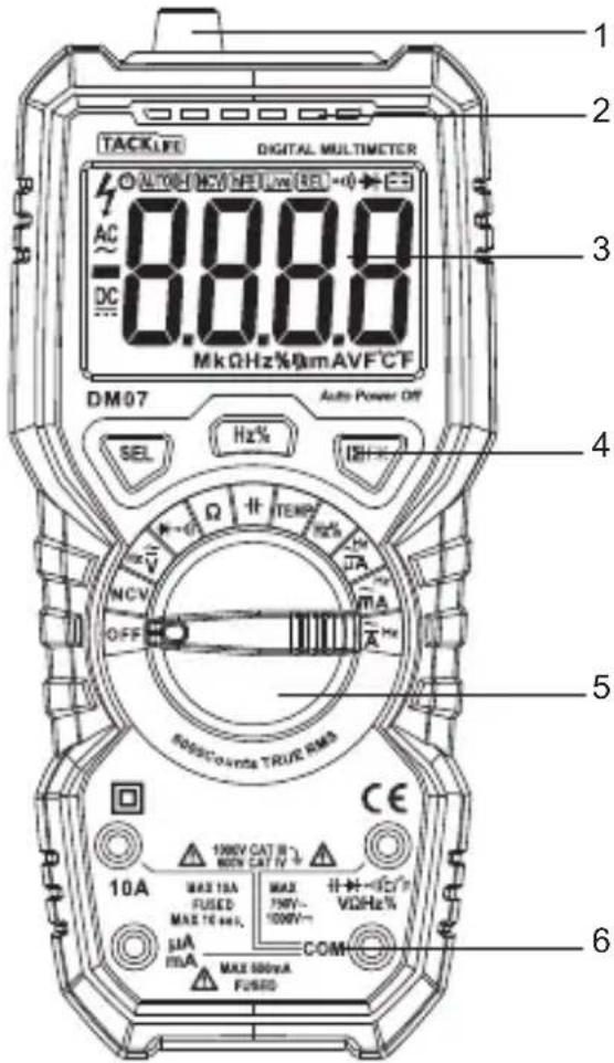
2. A Schematic Diagram for the Meter
This meter is a hand-held digital multi-meter with the function of displaying True RMS. It is a large-screen LCD unit with backlight and illumination light functions so that the user can easily recognize readings. It is equipped with the function of overload protection and the indicator of battery under voltage. Either for professionals, factories, schools, enthusiasts or households, it is an ideal multi-functional meter.
2.1 A Schematic Diagram for the Meter
Physical appearance
- Non-contact voltage detection area
- Non-contact voltage indicator
- LCD screen
- Key
- Rotary switch
- Input socket
2.2 Description of the symbols on the display unit
| Symbol | Description |
| Battery Under Voltage indicator/ Low Battery To avoid electric shock or personal injury as a result of incorrect reading, promptly replace the battery when the battery under voltage indicator appears. | |
| Auto power off indicator | |
| High voltage warning | |
| Negative input polarity indicator | |
| AC | Input voltage AC |
| DC | Input voltage DC |
| Continuity test mode | |
| Diode test mode | |
| AUTO | Automatic range measurement mode |
| Data hold mode | |
| °C, °F | Unit of temperature(°C: Celsius; °F: Fahrenheit) |
| % | Duty ratio |
| NCV | Non-contact AC voltage detection mode |
Table.1 Symbols (Continued)
| V, mV | V: | V: the unit of volt |
| mV: | Millivolt, 1x10⁻³or 0.001 volt | |
| A, mA, μA | A: | Ampere, the unit of current |
| mA: | Milliampere, 1x10⁻³or 0.001 ampere | |
| μA: | Microampere, 1x10⁻⁶or 0.000001 ampere | |
| Ω, kΩ, MΩ | Ω: | Ohm, the unit of electric resistance |
| kΩ: | Kilohm, 1000 Ohm | |
| MΩ: | Megaohm, 1,000,000 ohm | |
| MkHz | Hz: | Hz, the unit of frequency |
| KHz: | KHz, 1x10 Hz | |
| MHz: | MHz, 1x10⁶Hz or 1000 KHz | |
| mF,μF, nF | F: | Farad, the unit of capacitance |
| mF: | Millifarad, 1x10⁻³or 0.001 farad | |
| μF: | Microfarad, 1x10⁻⁶or 0.000001 farad | |
| nF: | nF, 1x10⁻⁹or 0.000000001 farad |
2.3 Description of functional keys
| Key | Description of functions |
| SEL | SEL keys, e. g. TEMP position: °C mode or °F mode. Voltage position or current position: ACV / DCV ACA / DCA →01) : Select the diode or beep on-off mode |
| HOLD(H) | Press the key to hold the measured value for the current moment Press the key again to cancel this function. |
| Press this key for more than 2 seconds, the backlight and the illumination indicator will be on; however, long press the key for more than 2 seconds again, you will turn off backlight and illumination indicator. If you don't press the key at all, the function will automatically be disenabled in 15 seconds. | |
| HZ / % | AC voltage or AC current position: Under AC voltage or AC current measuring state, press this key to select ACV/HZ/% or ACA/HZ/% measurement mode. Frequency positions: HZ or % measurement mode. |
2.4 Description of input socket
| input socket | Description |
| COM | All public input terminals to be measured are connected to test leads in black or the public output plugs of exclusive multi-function test sockets. Positive input terminals (connected to a test lead in red) for capacitor |
| °C / °F VΩHz% | measurement, diode measurement, beep on/off test, temperature measurement, voltage measurement, electric resistance, frequency, duty ratio. |
| μA mA | μA and mA positive input terminal (connected to a test lead in red). |
| 10A | 10A positive input terminal (connected to a test lead in red). |
2.5 Accessories
Operation Manual
Test lead
K-Type thermocouple
3. Operational guidelines
3.1 Normal operation
3.1.1 Hold mode
In the hold mode, the reading can be maintained on the display unit. Changing the measurement function position or pressing the key Hold again to exit the hold mode.
Hold mode: entry and exit
- Press the key “H” and the reading will be held and the symbol “H” will appear on the LCD screen.
- Press the key " H " again to restore the meter to its status for normal measurement.
3.1.2 Backlight & lighting
The meter is equipped with the functions of backlight and lighting so that the operator can access measurement results even if he is in a darker place. The backlight function can be enabled or disenabled by the steps below:
- Long press key for more than 2 seconds to enable backlight and illumination light.
- Long press key for more than 2 seconds again to manually disenable backlight and illumination light; wait for 15 seconds until the backlight and illumination light are automatically disabled.
3.1.3 Auto power off
If no operations are made in 15 minutes following the initialization, the meter will sound to remind the operator to automatically cut off power supply and enter the state of dormancy. The meter can be rebooted when the operator presses H / key in the auto power off mode.
3.2 Measurement guidelines
3.2.1 Measurement of AC voltage and DC voltage

To avoid any electric shock and/or damage to the meter, do not attempt a voltage measurement if the voltage (valid value) is 1,000V for DC current or 750V for AC current.
To avoid any electric shock and/or damage to the meter, don't attempt to impose between any public terminal and ground any voltage whose valid value is over 1, 000V for DC current or 750V for AC current.
The meter provides DC voltage measuring ranges as follows: 600.0mV, 6.000V, 60.00V, 600.0V and 1000V, and AC voltage measuring ranges: 6.000V, 60.00V, 600.0V and 750V.
Measurement of AC voltage or DC voltage.
- Turn the rotary switch to the position V, Press "SEL" to switch DC / AC voltage function.
- Connect the test lead in black and test lead in red to COM input socket and V input socket respectively.
- Use another two ends of the test lead to measure the voltage of the circuit to be measured. (In parallel connection with the circuit to be measured)
- Read the measured voltage value on LCD screen. When DC voltage measurement is attempted, the display unit will show the voltage polarity of the circuit connected to the pen-shaped meter in red.
Notes:
- Within the measuring range of DC voltage of 600mV and AC voltage of 6V, even if there is no input or no connection to the test lead, the meter will display some information. In this situation, press short circuit "V - Ω" and "COM" terminal to reset the meter to zero.
- Within the AC voltage function, press the key " HZ/%" to measure the frequency of the AC voltage source (40HZ~1KHZ).
- The value of the AC voltage measured with this meter is True RMS (root mean square). These measurements are accurate for sine wave and other waves (without DC offset), square wave, triangular wave and step wave.
3.2.2 Electric resistance measurement

To avoid the meter or the measured equipment from damage, do not attempt a resistance measurement unless the operator has already cut off all power sources for the circuit to be measured and fully discharged all high-voltage capacitors.
Ohm is the unit of electric resistance () .
The measuring ranges of electric resistance of this meter are 600.0 , 6.000k , 60.00kV , 600.0k , 6.000M and 60.00M .
Measurement of electric resistance
1 Turn the rotary switch to the position.
2. Connect the test lead in black and test lead in red to COM input socket and V/Ωinput socket respectively.
3.Use another two ends of the test lead to measure the electric resistance of the circuit to be measured.
4 Read the measured electric resistance value on LCD screen.
Notes:
- The measured value of the electric resistance of the circuit differs a bit from the rated value of the electric resistance.
- To ensure measurement accuracy, in attempting a low resistance measurement, first put two open-shaped meters in short circuit and capture the resistance reading of these short circuits. Then subtract the aforesaid reading from the measured resistance.
- At 60MΩposition, you have to wait a few seconds before the reading grow stable. This is quite normal for a high resistance measurement.
- When the meter is in open circuit, the display unit will show "OL" that indicates the measured value is over the measuring range.
3.2.3 Diode test

To avoid the meter or the measured equipment from damage, do not attempt a diode test unless the operator has already cut off all power sources for the circuit to be measured and fully discharged all high-voltage capacitors.
Diode test outside the circuit:
-
Turn the rotary switch to the position (\rightarrow \rightarrow \rightarrow \rightarrow \rightarrow \rightarrow \rightarrow \rightarrow \rightarrow \rightarrow \rightarrow \rightarrow \rightarrow \rightarrow \rightarrow \rightarrow \rightarrow \rightarrow \rightarrow \rightarrow \rightarrow \rightarrow \rightarrow \rightarrow \rightarrow \rightarrow \rightarrow \rightarrow \rightarrow \rightarrow \rightarrow \rightarrow \rightarrow \rightarrow \rightarrow \rightarrow \rightarrow \rightarrow \rightarrow \rightarrow \rightarrow \rightarrow \rightarrow \rightarrow \rightarrow \rightarrow \rightarrow \rightarrow \rightarrow \rightarrow \rightarrow
-
Connect the test leads in black and in red to COM input socket and V / Ωinput socket respectively.
- Connect the test leads in black and in red to the positive and negative poles of the diode to be tested respectively.
- The meter displays the forward bias value of the diode to be tested. If the polarity of the test lead is reversed, the meter will display "OL".
A normal diode still produces a forward voltage drop of 0.5V to 0.8V ; the reverse bias voltage reading depends on the variation in electric resistance of other channels between two pen-shaped meters.
3.2.4 Beep continuity test

To avoid the meter or the measured equipment from damage, do not attempt a beep continuity test unless the operator has already cut off all power sources for the circuit to be measured and fully discharged all high-voltage capacitors.
Steps for a continuity test:
- Turn the rotary switch to the position
- Connect the test lead in black and test lead in red to COM input socket and V / Ωinput socket respectively.
- Use another two ends of the test lead to measure the resistance of the circuit to be measured. If the measured distance is no more than 40 , the sensor LED (green indicator) will be on and the beeper will sound continuously. If the measured resistance is between 40 and 60 , the sensor LED (red indicator) will be on.
3.2.5 Capacitance measurement

To avoid the meter or the measured equipment from damage, do not attempt a capacitance measurement unless the operator has already cut off all power sources for the circuit to be measured and fully discharged all high-voltage capacitors. Use the DC voltage position to determine that all capacitors have been discharged.
The measuring ranges for the capacitance of this meter are 6.000nF, 60.00nF, 600.0nF, 6.000ΩF, 60.00ΩF and 600.0ΩF, 6mF, 100mF.
Measurement of capacitance:
- Turn the rotary switch to the position
- Connect the test leads in black and in red to COM input socket and - input socket respectively.
- Use another two ends of the test lead to measure the capacitance of the capacitor to be measured, and capture the measured value on LCD screen.
Notes:
The measurement of a large capacitance requires a given period of stabilization of reading.
- To avoid damage to the meter, the measurement of a capacitor with polarities requires much attention to its polarity.
3.2.6 Frequency measurement

To avoid any electric shock and/or damage to the meter, do not attempt a frequency measurement if the voltage is over 250V for DC current or AC current (valid value).
Frequency measurement:
- Turn the rotary switch to the position HZ% , Press "Hz%" to switch HZ or % function.
- Connect the test leads in black and in red to COM input socket and Hz input socket respectively.
- Use another two ends of the test lead to measure the frequency of the circuit to be measured.
- Read the measured frequency on LCD screen.
3.2.7 Current measurement
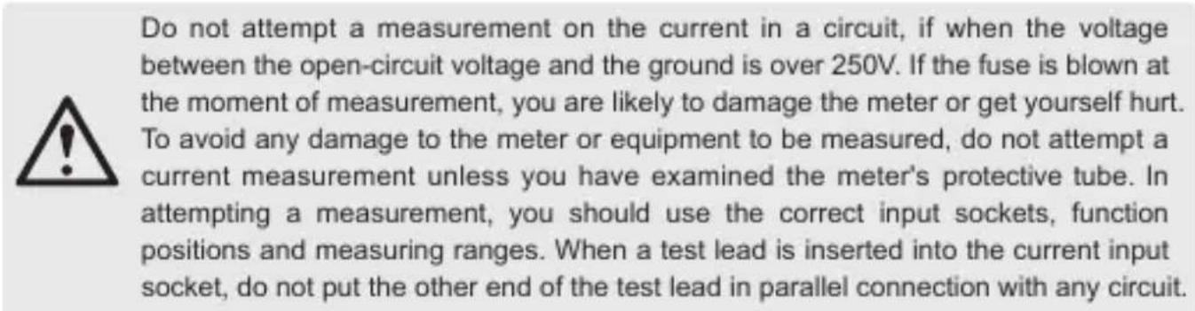
The meter provides DC current measuring ranges as follows: 60ΩA, 600ΩA, 6mA, 60.00mA, 600.0mA and 10.00A; and AC current measuring ranges: 60ΩA, 600ΩA, 6mA, 60.0mA, 600.0mA and 10.00A.
Measurement of current:
- Turn the rotary switch to the appropriate position, Press "SEL" to switch DC/AC current function.
- Connect the test lead in black to COM input socket. Connect the test lead in red to a mA input socket when the measured current is less than 600mA ; connect the test lead in red to a 10A input socket when the measured current is 600mA 10A .
- Disconnection of the circuit to be measured Connect the test lead in black to the end of disconnected circuit (the voltage is lower) and connect the test lead in red to the end of the disconnected circuit (voltage is higher).
- Connect the power to the circuit and capture the displayed reading. If the display unit only shows "OL", it means the input is over the selected measuring range. At this moment, turn the rotary switch to a higher measuring range.
Notes:
Within the AC current function, press the key "HZ / %" to measure the frequency of the AC current source (40HZ~1KHZ).
3.2.8 NCV test (non-contact voltage detection)
Turn the rotary switch to NCV position, and place the top of the meter approach the conductor. If the meter detects the AC voltage, the indicators for signal density (high, medium and low) will be on in accordance with the detected density, while the beeper will sounds alarms at different frequencies.
Note:
- Voltage may still remain in the absence of any indication. The operator shall not rely on non-contact voltage detector to check the presence of voltage. The detection operation may be affected by various factors, including socket design, insulation thickness and type.
-
When the voltage is input into the meter's input terminal, the voltage sensor LED may be on as a result of induced voltage.
-
External sources of interference (like flashlight and motor) may trigger non-contact voltage detection.
3.2.9 Measuring temperature
Put the range switch at the gear of TEMP. Insert the red plug of the thermocouple into the end of ^ C , and insert the black plug of the thermocouple into COM socket. Directly read the temperature value from the display screen after the reading is stable.
Notes:
The maximum measuring temperature for the K-type thermocouple dispatched at random is 25^ , and its instant measuring value can reach 300^ .
4. Technical parameters
4.1 Overall parameters
- Operating environment:
600V CAT IV and 1000V CAT. III Pollution level: 2Altitude < 2000m
Working temperature & humidity: 0~40OC (The requirements will not be considered when temperature is less than 10^ and relative humidity is below 80% ).
Storage temperature & humidity: -10~60OC (batteries shall be removed when RH is below 70%). - Coefficient of temperature: 0.1 × accuracy / OC (<18 °C or >28 °C).
- Allowable max voltage between terminal to be measured and ground: 1000V DC or 750V AC (valid value)
- Protection of protective tube: mA position: protective tube FF 600mA / 250V; A position protective tube FF 10A / 250V
- Rotation rate: approximately 3 revolutions / second.
- Display unit: 6000 counts displayed on LCD screen. Automatically display the symbol for unit in accordance with measurement function position.
- Outrange indication: the LCD screen will display "OL".
- Battery Low indication: "—" will appear when the battery's voltage is below the normal working voltage.
- Input polarity indication: " - " will automatically appear.
Power: 4 x 1.5V AA battery - Dimensions: 190 mm( L) × 89 mm( W) × 50 mm( H) .
- Weight: approximately 380g (inclusive of batteries).
4.2 Precision indicator
| Measuring range | Resolution | Accuracy |
| 600 mV | 0.1 mV | ±(0.5% Reading + 3 digits) |
| 6 V | 1 mV | |
| 60 V | 10 mV | |
| 600 V | 100 mV | |
| 1000 V | 1 V | ±(0.5% Reading + 3 digits) |
Input impedance:10MΩ
Maximal input voltage: 1000Vdc or 750Vac valid value
4.2.2 AC voltage
| Measuring range | Resolution | Accuracy |
| 6 V | 1 mV | ± (0.8% readings +3 digits) |
| 60 V | 10 mV | |
| 600 V | 100 mV | ± (1% readings +10 digits) |
| 750 V | 1 V |
Input impedance:10MΩ
Maximal input voltage: 1000Vdc or 750Vac valid value
Frequency response: 40Hz-1kHz True RMS
4.2.3 Frequency
| Measuring range | Resolution | Accuracy |
| 9.999 Hz | 0.001 Hz | ± (1% Reading + 3 digits) |
| 99.99 Hz | 0.01 Hz | |
| 999.9 Hz | 0.1 Hz | |
| 9.999 KHz | 0.001 KHz | |
| 99.99 KHz | 0.01 KHz | |
| 999.9 KHz | 0.1 KHz | |
| 9.999 MHz | 0.001 MHz |
Input voltage range: 200mV -10V ac valid value
Overload protection: 600V DC / AC
4.2.4 Electric resistance
| Measuring range | Resolution | Accuracy |
| 600 Ω | 0.1 Ω | ± (0.8% Reading + 3 digits) |
| 6 kΩ | 1 Ω | |
| 60 kΩ | 10 Ω | |
| 600 kΩ | 100 Ω | |
| 6 MΩ | 1 kΩ | |
| 60 MΩ | 10 kΩ | ± (1.2% Reading + 30 digits) |
Overload protection: 600V DC / AC
Open-circuit voltage: 1V
4.2.5 Diode
| Functions | Measuring range | Resolution | Testing conditions |
| Diode test | 0-3 V | 0.001 V | Forward DC current: approximately 1mA; Open-circuit voltage: approximately 3.2V. The display unit shows the approximate value of the diode's forward voltage drop. |
Overload protection: 600V DC / A
4.2.6 Beeper continuity
| Functions | Measuring range | Resolution | Description | Testing conditions |
| 0.1 | 600 Ω | 0.1 Ω | When the built-in beeper sounds and the accompanying green indicator is on, the measured resistance shall not be over 30Ω. The red indicator will be on when the resistance is 40Ω-60Ω. | Open-circuit voltage: approximately 1V |
Overload protection: 600V DC / AC
4.2.7 Capacitor
| Measuring range | Resolution | Accuracy |
| 6 nF | 0.001 nF | ± (4.0% Reading +30 digits) |
| 60 nF | 0.01 nF | ± (4.0% Reading +3 digits) |
| 600 nF | 0.1 nF | |
| 6 μF | 1 nF | |
| 60 μF | 10 nF | |
| 600 μF | 100 nF | |
| 6 mF | 1 uF | |
| 100 mF | 0.01 mF | ± (5.0% Reading + 3 digits) |
Overload protection: 600V DC / AC
4.2.8 DC current
| Measuring range | Resolution | Accuracy |
| 60 μA | 0.01 μA | |
| 600 μA | 0.1 μA | ±(0.8% Reading + 3 digits) |
| 6 mA | 0.001 mA | |
| 60 mA | 0.01 mA | |
| 600 mA | 0.1 mA | |
| 10.00 A | 10 mA | ±(1.2% Reading + 3 digits) |
Overload protection: protective tube for mA measuring range (FF600mA/250V); protective tube for 10A measuring range (FF10A/250V).
Maximal input current: mA position: 600mA DC/AC (valid value);
10A position: 10A DC/AC (valid value)
When the measured current is over 5A, the duration of continuous measurement shall not be over 10 seconds. The current measurement shall be carried out 1 minute after the completion of previous measurement.
4.2.9 AC current
| Measuring range | Resolution | Accuracy |
| 60 μA | 0.01 μA | ±(1% Reading + 3 digits) |
| 600 μA | 0.1 μA | |
| 6 mA | 0.001 mA | |
| 60 mA | 0.01 mA | |
| 600 mA | 0.1 mA | |
| 10 A | 10 mA | ±(1.5% Reading + 3 digits) |
Overload protection: protective casing for mA measuring range (FF600mA / 250V); protective casing for 10A measuring range (FF10A / 250V).
Maximal input voltage: mA position: 600mA DC / AC (valid value);
10A position: 10A DC / AC (valid value)
When the measured current is over 5A, the duration of continuous measurement shall not be over 10 seconds. The current measurement shall be carried out 1 minute after the completion of previous measurement.
Frequency response: 40Hz-1kHz True RMS
4.2.10 Temperature
| Measuring range | Resolution | Accuracy | |
| °C | 1°C | -20 °C~1000 °C | ±(1.0%+3) reading |
| °F | 1°F | -4 °F~1832 °F | ±(1.0%+3) reading |
Overload protection: 600V DC / AC
5. Meter maintenance
This section provides the basic information on maintenance, including the descriptions about replacement of protective tubes and batteries. Do not attempt the meter maintenance unless you are experienced in maintenance and have read the information on calibration, performance test and maintenance.
5.1 General maintenance
To avoid any electric shock or damage to the meter, do not attempt to clean the inside of the meter. You must remove the line connecting a test lead to input signals, before opening the case or battery cover.
You must regularly use damp cloth and a small quantity of detergent to clean the meter's shell.
Don't attempt the use of any aberrant or chemical solvent.
The dirty or damp input socket may affect reading.
Steps for cleaning input sockets:
- Disenable the meter and pull all test leads out of the input socket.
- Clean up all dirty substances on sockets.
- Use a new cotton ball with a detergent or lubricant to clean each socket, because lubricant can prevent the socket vulnerable to dampness from pollution.
5.2 Battery & Fuse Replacement

To avoid any electric shock or personal injury as a result of incorrect reading, replace batteries once the symbol + appear on the display unit. Only the designated fuse (600mA/1000V, 10A/1000V quick-acting fuse) can be used. To avoid any electric shock or personal injury, don't attempt to open the battery cover to replace batteries, unless you have already powered off the device and carried out an examination to ensure that the test lead has been disconnected from the circuit to be measured.
Batteries must be replaced by the following steps:
- Cut off the power to the meter.
- Pull all test leads out of the input socket.
- Use a screw driver to unscrew the bolts that are used to fix battery cover.
- Take off the battery cover.
- Remove the old batteries or the damaged protective tubes.
- Make replacements with new 4 × 1.5 ~V AA batteries or new protective casing.
- Remount the battery cover and fix a bolt.
1.2 Input protection measures
Table.1 Symbols (Continued)
| V, mV | V: | V: die Einheit der Spannung |
| mV: | Millivolt, 1x10⁻³or 0.001 volt. | |
| A, mA, μA | A: | Ampere, die Einheit des Stroms. |
| mA: | Milliampere, 1x10⁻³or 0.001 ampere. | |
| μA: | Microampere, 1x10⁻⁶or 0.000001 ampere. | |
| Ω, kΩ, MΩ | Ω: | Ohm, die Einheit des Widersands |
| kΩ: | Kilohm, 1000 Ohm | |
| MΩ: | Megaohm, 1,000,000 ohm | |
| MkHz | Hz: | Hz,die Einheit der Freqenz |
| KHz: | KHz, 1x10³Hz | |
| MHz: | MHz, 1x10⁶Hz or 1000 KHz | |
| mF,μF, nF | F: | Farad, die Einheit der Kapazitanz |
| mF: | Millifarad, 1x10⁻³or 0.001 farad | |
| μF: | Microfarad, 1x10⁻⁶or 0.000001 farad | |
| nF: | nF, 1x10⁻⁹or 0.000000001 farad |
Batteries must be replaced by the following steps:
Table.1 Symbols (Continued)
| V, mV | V: | V:L'unité de volt |
| mV: | Millivolt, 1x10⁻³or 0.001 volt | |
| A, mA, μA | A: | Ampère, l'unité de courant. |
| mA: | Milliampere, 1x10⁻³or 0.001 ampère | |
| μA: | Microampère, 1x10⁻⁶or 0.000001 ampère | |
| Ω, kΩ, MΩ | Ω: | Ohm, l'unité de résistance électrique. |
| kΩ: | Kilohm, 1000 Ohm | |
| MΩ: | Megaohm, 1,000,000 ohm | |
| MkHz | Hz: | Hz, l'unité de fréquence |
| KHz: | KHz, 1x10³Hz | |
| MHz: | MHz, 1x10⁶Hz or 1000 KHz | |
| mF,μF, nF | F: | Farad, l'unité de capacitance. |
| mF: | Millifarad, 1x10⁻³or 0.001 farad | |
| μF: | Microfarad, 1x10⁻⁶or 0.000001 farad | |
| nF: | nF, 1x10⁻⁹or 0.000000001 farad |
Overload protection: 600V DC/AC
Open-circuit voltage: 1V
4.2.5 Diodo
3. Linee guida operative
4.2.6 Beeper continuity
This is the way of protecting the operation of the system.
5.1一般的なルンデナス

ADD: No.B714, Niulanqian Building, Minzhi Road,
Longhua District, Shenzhen, Guangdong, China 518000
Made in China
C∈FCRoHS

- Safety information
- Safety instructions
- Safety considerations
- Safety symbol:
- Maintenance practices for safety
- Input protection measures
- A Schematic Diagram for the Meter
- A Schematic Diagram for the Meter
- Description of the symbols on the display unit
- Description of functional keys
- Description of input socket
- Accessories
- Operational guidelines
- Normal operation
- Hold mode
- Backlight & lighting
- Auto power off
- Measurement guidelines
- Measurement of AC voltage and DC voltage
- Notes:
- Electric resistance measurement
- Diode test
- Beep continuity test
- Frequency measurement
- Current measurement
- NCV test (non-contact voltage detection)
- Note:
- Measuring temperature
- Technical parameters
- Overall parameters
- Precision indicator
- AC voltage
- Frequency
- Electric resistance
- Diode
- AC current
- Temperature
- Meter maintenance
- General maintenance
- Battery & Fuse Replacement
- Diodo
- Linee guida operative
- Beeper continuity
- 5.1一般的なルンデナス
Brand : Tacklife
Model : DM07
Category : Multimeter