
DIVAcondens F28 - Boiler FERROLI - Free user manual and instructions
Find the device manual for free DIVAcondens F28 FERROLI in PDF.
| Product type | Wall-mounted condensing boiler |
| Brand | Ferroli |
| Model | DIVAcondens F28 |
| Useful thermal power (heating 80/60°C) | 27 kW |
| Useful thermal power (heating 50/30°C) | 29 kW |
| Empty weight | 35 kg |
| Power supply | 230 V / 50 Hz, 110 W |
| Gas type | Natural gas (G20) or LPG (G31) |
| Gas supply pressure (G20) | 20 mbar |
| Heating temperature adjustment | 30 °C to 80 °C |
| Domestic hot water temperature adjustment | 40 °C to 55 °C |
| Installation water pressure (cold) | 1.0 bar |
| Expansion vessel capacity | 8 litres (pre-charged to 1 bar) |
| Energy efficiency class | ★★★★★ (5 stars) |
| NOx emission class | 3 |
| Protection rating | IP X5D |
| Draft type | Room-sealed, forced draft |
| Allowed flue ducts | Coaxial 60/100 or 80/125, separate Ø80 |
| Frost protection function | Integrated (active only if boiler powered) |
| Recommended maintenance | Annual by a qualified professional |
| Safety | Safety thermostat, air pressure switch, overheat safety |
Frequently Asked Questions - DIVAcondens F28 FERROLI
User questions about DIVAcondens F28 FERROLI
0 question about this device. Answer the ones you know or ask your own.
Ask a new question about this device
Download the instructions for your Boiler in PDF format for free! Find your manual DIVAcondens F28 - FERROLI and take your electronic device back in hand. On this page are published all the documents necessary for the use of your device. DIVAcondens F28 by FERROLI.
USER MANUAL DIVAcondens F28 FERROLI
- Carefully read and follow the instructions contained in this instruction booklet.
- After boiler installation, inform the user regarding its operation and give him this manual, which is an integral and essential part of the product and must be kept with care for future reference.
- Installation and maintenance must be carried out by professionally qualified personnel, in compliance with the current regulations and according to the manufacturer's instructions. Do not carry out any operation on the sealed control parts.
- Incorrect installation or inadequate maintenance can result in damage or injury. The Manufacturer declines any liability for damage due to errors in installation and use, or failure to follow the instructions.
- Before carrying out any cleaning or maintenance operation, disconnect the unit from the electrical power supply using the switch and/or the special cut-off devices.
- In case of a fault and/or poor operation, deactivate the unit and do not try to repair it or directly intervene. Contact professionally qualified personnel. Any repair/replacement of the products must only be carried out by qualified personnel using original replacement parts. Failure to comply with the above could affect the safety of the unit.
- This unit must only be used for its intended purpose. Any other use is deemed improper and therefore hazardous.
- The packing materials are potentially hazardous and must not be left within the reach of children.
- The unit must not be used by people (including children) with limited physical, sensory or mental abilities or without experience and knowledge of it, unless instructed or supervised in its use by someone responsible for their safety.
- The unit and its accessories must be appropriately disposed of, in compliance with the current regulations.
- The images given in this manual are a simplified representation of the product. In this representation there may be slight and insignificant differences with respect to the product supplied.
2. OPERATING INSTRUCTIONS
2.1 Introduction
Dear Customer,
DIVAcondens F24/F28 is a high-efficiency sealed chamber condensing heat generator for heating and hot water production running on natural gas or LPG, and equipped with a microprocessor control system.
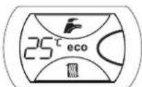
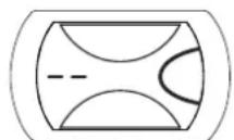
2.2 Control panel
Panel
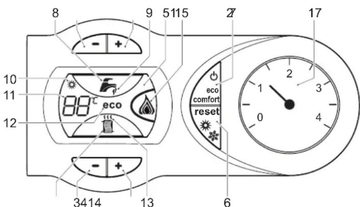
fig.1 - Control panel
Panel key fig. 1
1 DHW temperature setting decrease button
2 DHW temperature setting increase button
3 Heating system temperature setting decrease button
4 Heating system temperature setting increase button
5 Display
6 Summer/Winter mode selection - Reset button
7 Unit On/Off - Economy/Comfort mode selection button
8 DHW symbol
9 DHW mode
10 Summer mode
11 Multifunction
12 Eco (Economy) mode
13 Heating
14 Heating symbol
15 Burner lit and actual power level
17 Water gauge
Indication during operation
Heating
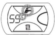
A heating demand (generated by the Room Thermostat or Remote Timer Control) is indicated by flashing of the hot air above the radiator on the display.
The display (detail 11 - fig. 1) shows the actual heating delivery temperature and, during heating standby time, the message "d2".
Domestic hot water (DHW)
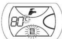
A DHW demand (generated by drawing domestic hot water) is indicated by flashing of the hot water under the tap on the display.
The display (detail 11 - fig. 1) shows the actual DHW outlet temperature and, during DHW standby time, the message "d1".
Comfort
A Comfort demand (reinstatement of temperature inside the boiler) is indicated by flashing of the water under the tap on the display. The display (detail 11 - fig. 1) shows the actual temperature of the water in the boiler.
Fault
In case of a fault (see cap. 4.4) the display shows the fault code (detail 11 - cap. 4.4) and during safety pause times the message "d3".
2.3 Lighting and shutdown
Connection to the power supply
During the first 5 seconds the display will also show the card software release.
- Open the gas cock ahead of the boiler.
- The boiler is now ready to function automatically whenever domestic hot water is drawn or in case of a heating demand (generated by Room Thermostat or Remote Temperature Control).
Switching the boller off and on
Press the On/Off button (detail 7 - fig. 1) for 5 seconds.
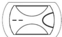
fig.2-Turning the boiler off
When the boiler is switched off, the electronic board is still powered. Domestic hot water and heating are disabled. The antifreeze system remains activated. To relight the boiler, press the On/Off button (detail 7 fig. 1) again for 5 seconds.
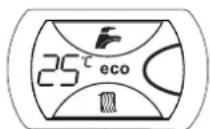
fig. 3
The boiler will be immediately ready to work whenever domestic hot water is drawn or in case of a heating demand (generated by the Room Thermostat or the Remote Timer control).

The antifreeze system does not work when the power and/or gas to the unit are turned off. To avoid damage caused by freezing during long shutdowns in winter, it is advisable to drain all water from the boiler, the DHW circuit and the heating system water; or drain just the DHW circuit and add a suitable antifreeze to the heating system, as prescribed in sec. 3.3.
2.4 Adjustments
Summer/Winter Swithover
Press the summer/winter button (detail 6 - fig. 1) for 2 seconds.
The display activates the Summer symbol (detail 10 - fig. 1): the boiler will only deliver domestic hot water. The antifreeze system remains activated.
To deactivate the Summer mode, press the summer/winter button (detail 6 - fig. 1) again for 2 seconds.
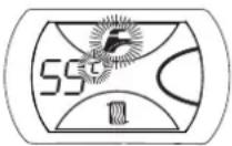
Heating temperature adjustment
Use the heating buttons (details 3 and 4 - fig. 1) to adjust the temperature from a min. of 30°C to a max. of 80°C ; in any case, it is advisable not to operate the boiler below 45°C .
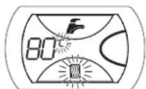
fig. 4
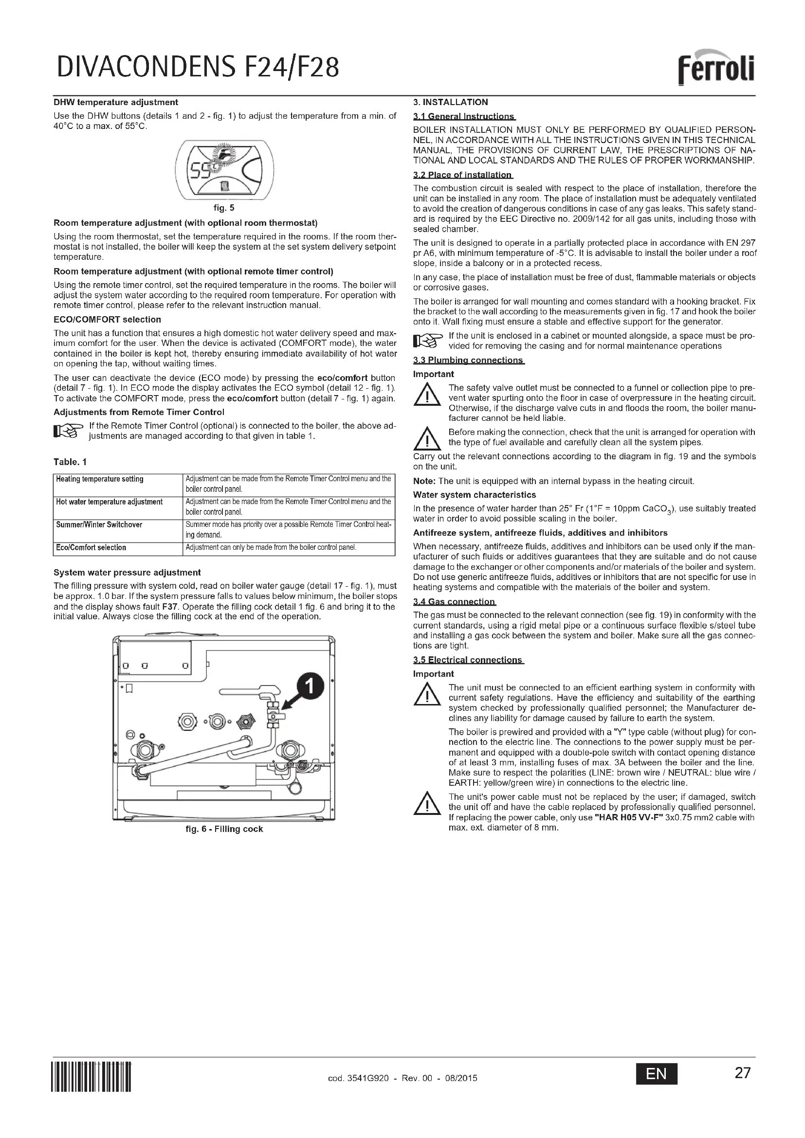
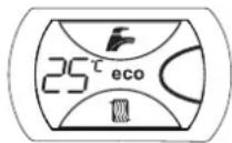
DHW temperature adjustment
Use the DHW buttons (details 1 and 2 - fig. 1) to adjust the temperature from a min. of 40°C to a max. of 55°C .
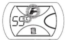
fig.5
Room temperature adjustment (with optional room thermostat)
Using the room thermostat, set the temperature required in the rooms. If the room thermostat is not installed, the boiler will keep the system at the set system delivery setpoint temperature.
Room temperature adjustment (with optional remote timer control)
Using the remote timer control, set the required temperature in the rooms. The boiler will adjust the system water according to the required room temperature. For operation with remote timer control, please refer to the relevant instruction manual.
ECO/COMFORT selection
The unit has a function that ensures a high domestic hot water delivery speed and maximum comfort for the user. When the device is activated (COMFORT mode), the water contained in the boiler is kept hot, thereby ensuring immediate availability of hot water on opening the tap, without waiting times.
The user can deactivate the device (ECO mode) by pressing the eco/comfort button (detail 7 - fig. 1). In ECO mode the display activates the ECO symbol (detail 12 - fig. 1). To activate the COMFORT mode, press the eco/comfort button (detail 7 - fig. 1) again.
Adjustments from Remote Timer Control

If the Remote Timer Control (optional) is connected to the boiler, the above adjustments are managed according to that given in table 1.
Table.1
| Heating temperature setting | Adjustment can be made from the Remote Timer Control menu and the boiler control panel. |
| Hot water temperature adjustment | Adjustment can be made from the Remote Timer Control menu and the boiler control panel. |
| Summer/Winter Swithover | Summer mode has priority over a possible Remote Timer Control heating demand. |
| Eco/Comfort selection | Adjustment can only be made from the boiler control panel. |
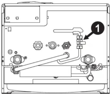
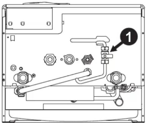
System water pressure adjustment
The filling pressure with system cold, read on boiler water gauge (detail 17 - fig. 1), must be approx. 1.0 bar. If the system pressure falls to values below minimum, the boiler stops and the display shows fault F37. Operate the filling cock detail 1 fig. 6 and bring it to the initial value. Always close the filling cock at the end of the operation.
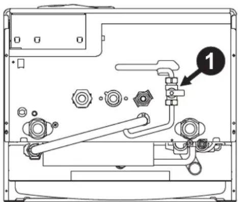
fig.6-Filling cock
3. INSTALLATION
3.1 General Instructions
BOILER INSTALLATION MUST ONLY BE PERFORMED BY QUALIFIED PERSONNEL, IN ACCORDANCE WITH ALL THE INSTRUCTIONS GIVEN IN THIS TECHNICAL MANUAL, THE PROVISIONS OF CURRENT LAW, THE PREScriptions OF NATIONAL AND LOCAL STANDARDS AND THE RULES OF PROPER WORKMANSHIP.
3.2 Place of installation
The combustion circuit is sealed with respect to the place of installation, therefore the unit can be installed in any room. The place of installation must be adequately ventilated to avoid the creation of dangerous conditions in case of any gas leaks. This safety standard is required by the EEC Directive no. 2009/142 for all gas units, including those with sealed chamber.
The unit is designed to operate in a partially protected place in accordance with EN 297 or A6, with minimum temperature of -5°C . It is advisable to install the boiler under a roof slope, inside a balcony or in a protected recess.
In any case, the place of installation must be free of dust, flammable materials or objects or corrosive gases.
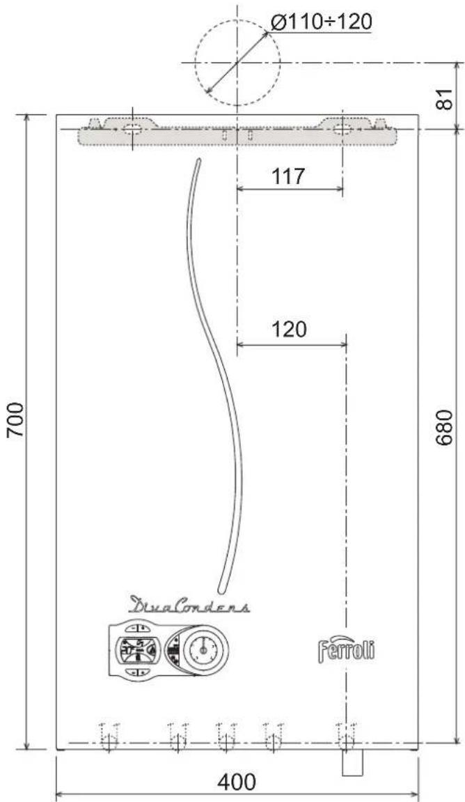
The boiler is arranged for wall mounting and comes standard with a hooking bracket. Fix the bracket to the wall according to the measurements given in fig. 17 and hook the boiler onto it. Wall fixing must ensure a stable and effective support for the generator.

If the unit is enclosed in a cabinet or mounted alongside, a space must be provided for removing the casing and for normal maintenance operations
3.3 Plumbing connections
Important

The safety valve outlet must be connected to a funnel or collection pipe to prevent water spurting onto the floor in case of overpressure in the heating circuit. Otherwise, if the discharge valve cuts in and floods the room, the boiler manufacturer cannot be held liable.

Before making the connection, check that the unit is arranged for operation with the type of fuel available and carefully clean all the system pipes.
Carry out the relevant connections according to the diagram in fig. 19 and the symbols on the unit.
Note: The unit is equipped with an internal bypass in the heating circuit.
Water system characteristics
In the presence of water harder than 25°Fr (1°F = 10ppmCaCO3) use suitably treated water in order to avoid possible scaling in the boiler.
Antifreeze system, antifreeze fluids, additives and inhibitors
When necessary, antifreeze fluids, additives and inhibitors can be used only if the manufacturer of such fluids or additives guarantees that they are suitable and do not cause damage to the exchanger or other components and/or materials of the boiler and system. Do not use generic antifreeze fluids, additives or inhibitors that are not specific for use in heating systems and compatible with the materials of the boiler and system.
3.4 Gas connection
The gas must be connected to the relevant connection (see fig. 19) in conformity with the current standards, using a rigid metal pipe or a continuous surface flexible s/steel tube and installing a gas cock between the system and boiler. Make sure all the gas connections are tight.
3.5 Electrical connections
Important

The unit must be connected to an efficient earthing system in conformity with current safety regulations. Have the efficiency and suitability of the earthing system checked by professionally qualified personnel; the Manufacturer declines any liability for damage caused by failure to earth the system.
The boiler is prewired and provided with a "Y" type cable (without plug) for connection to the electric line. The connections to the power supply must be permanent and equipped with a double-pole switch with contact opening distance of at least 3mm , installing fuses of max. 3A between the boiler and the line. Make sure to respect the polarities (LINE: brown wire / NEUTRAL: blue wire / EARTH: yellow/green wire) in connections to the electric line.

The unit's power cable must not be replaced by the user; if damaged, switch the unit off and have the cable replaced by professionally qualified personnel. If replacing the power cable, only use "HAR H05 VV-F" 3 × 0.75 mm2 cable with max. ext. diameter of 8 mm .
Room thermostat (optional)

IMPORTANT: THE ROOM THERMOSTAT MUST HAVE VOLTAGE-FREE CONTACTS. CONNECTING 230 V TO THE ROOM THERMOSTAT TERMINALS WILL PERMANENTLY DAMAGE THE ELECTRONIC BOARD.
When connecting time controls or a timer, do not take the power supply for these devices from their breaking contacts. Their power supply must be by means of direct connection from the mains or with batteries, depending on the kind of device.
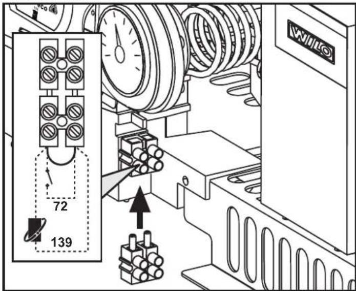
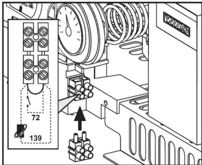
Accessing the electrical terminal block
The electrical terminal block can be accessed after removing the casing. The arrangement of the terminals for the various connections is also given in the wiring diagram in fig. 24.

fig.7 - Accessing the terminal block
3.6 Fume ducts
Important
The unit is a "C type" with sealed chamber and forced draught, the air inlet and fume outlet must be connected to one of the following extraction/suction systems. The unit is approved for operation with all the Cny flue configurations given on the dataplate. Some configurations may be expressly limited or not permitted by law, standards or local regulations. Before installation, check and carefully follow the instructions. Also, comply with the instructions on the positioning of wall and/or roof terminals and the minimum distances from windows, walls, ventilation openings, etc.
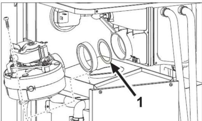
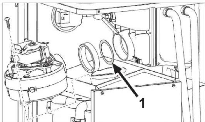
Baffles
Boiler operation requires fitting the baffles supplied with the unit, according to the following tables.
Before inserting the fume outlet pipe, it is therefore necessary to check there is the right diaphragm (when it is to be used) and that it is correctly positioned. Boilers are fitted as standard with the diaphragm with the smallest diameter. To replace the baffle (rf. 1 - fig. 8), proceed as indicated in fig. 8.
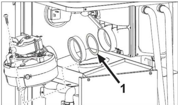
fig.8
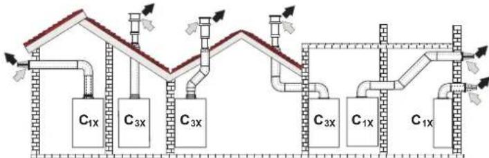
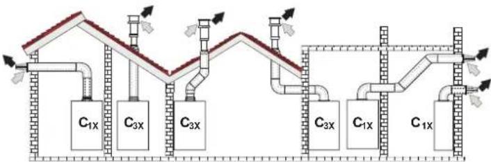
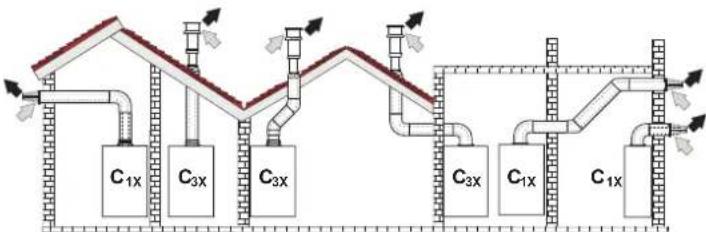
Connection with coaxial pipes
fig. 9 - Examples of connection with coaxial pipes (Air / Figs)
Table.2 - Typology
| Type Description | |
| C1X | Wall horizontal exhaust and inlet |
| C3X | Roof vertical exhaust and inlet |
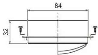
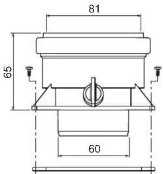
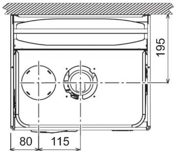
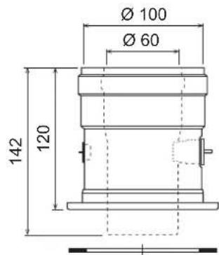
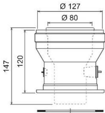
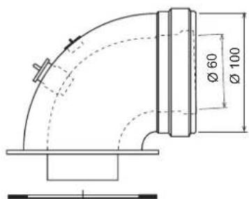
For coaxial connection, fit the unit with one of the following starting accessories. For the wall hole dimensions, refer to the figure on the cover. Any horizontal sections of the fume exhaust must be kept sloping slightly towards the boiler, to prevent possible condensate from flowing back towards the outside and causing dripping.
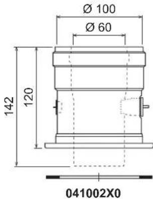
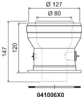
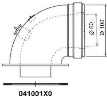
fig. 10 - Starting accessory for coaxial ducts
Table. 3 - Baffles for coaxial ducts
| Coaxial 60/100 Coaxial | 80/125 | |||
| Max. permissible length 6 m 12 m | ||||
| Reduction factor 90° bend 1 m 0.5 m | ||||
| Reduction factor 45° bend 0.5 m 0.25 m | ||||
| Baffle to use | 0÷2 m | 45 | 0÷6 m | ∅45 |
| 2÷4 m | 50 | 6÷12 m | no baffle | |
| 4÷6 m | no baffle | |||
Connection with separate pipes
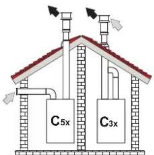
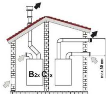
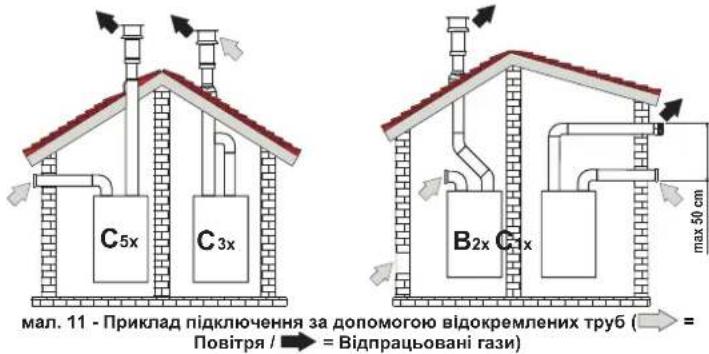
fig. 11 - Examples of connection with separate pipes (E Air / = Figures)
Table. 4 - Typology
| Type Description | |
| C1X | Wall horizontal exhaust and intake. The inlet/outlet terminals must be concentric or close enough to be undergo similar wind conditions (within 50 cm) |
| C3X | Roof vertical exhaust and intake. Inlet/outlet terminals like for C12 |
| C5X | Wall or roof exhaust and intake separate or in any case in areas with different pressures. The exhaust and intake must not be positioned on opposite walls. |
| C6X | Intake and exhaust with separately certified pipes (EN 1856/1) |
| B2X | Intake from installation room and wall or roof exhaustIMPORTANT - THE ROOM MUST BE PROVIDED WITH APPROPRIATE VENTILATION |
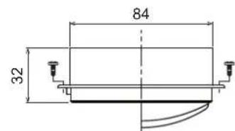
For connection of the separate ducts, fit the unit with the following starting accessory:
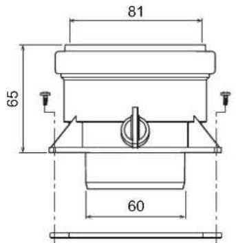
041064X0
fig. 12 - Starting accessory for separate ducts
Before proceeding with installation make sure the maximum permissible length has not been exceeded, by means of a simple calculation:
- Completely establish the layout of the system of split flues, including accessories and outlet terminals.
- Consult the table 6 and identify the losses in meq (equivalent metres) of every component, according to the installation position.
- Check that the sum total of losses is less than or equal to the maximum permissible length in table 5.
Table. 5 - Baffles for separate ducts
| Separate ducts | ||
| Max. permissible length | 55 m_eq | |
| Baffle to use | 0 ÷ 15 m_eq | Ø 45 |
| 15 ÷ 35 m_eq | Ø 50 | |
| 35 ÷ 55 m_eq | No baffle | |
Table. 6 - Accessories
| Losses in \(m_{\text{eq}}\) | |||||
| Air inlet | Fume exhaust | ||||
| Vertical Horizontal | |||||
| ∅ 80 | PIPE | 1 m M/F 1KWMA83W 1.0 1.6 | 2.0 | ||
| BEND | 45° M/F 1KWMA85W 1.2 1.8 | ||||
| 90° M/F 1KWMA01W 1.5 2.0 | |||||
| PIPE SECTION | with test point | 1KWMA70W 0.3 | 0.3 | ||
| TERMINAL | air, wall | 1KWMA85A 2.0 | - | ||
| fumes, wall with antiwind | 1KWMA86A | - | 5.0 | ||
| FLUE | Split air/fumes 80/80 | 010027X0 | - | 12.0 | |
| Fume outlet only Ø80 010026 | x0 + 1KWMA86U | - | 4.0 | ||
| ∅ 60 | PIPE | 1 m M/F 1KWMA89W | 6.0 | ||
| BEND | 90° M/F 1KWMA88W | 4.5 | |||
| REDUCTION | 80/60 | 041050X0 | 5.0 | ||
| TERMINAL | fumes, wall with antiwind | 1KWMA90A | 7.0 | ||
| ! | ATTENTION: CONSIDER THE HIGH PRESSURE LOSSES OF Ø60 ACCESSORIES; USE THEM ONLY IF NECESSARY AND AT THE LAST FUME EXHAUST SECTION. | ||||
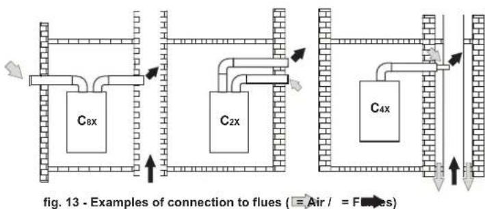
Connection to collective flues
Table. 7 - Typology
| Type | Description |
| C2X | Intake and exhaust in common flue (intake and exhaust in same flue) |
| C4X | Intake and exhaust in common and separate flues , but undergoing similar wind conditions |
| C8X | Exhaust in single or common flue and wall intake |
| B3X | Intake from installation room by means of concentric duct (that encloses the exhaust) and exhaust in common flue with natural draught IMPORTANT - THE ROOM MUST BE PROVIDED WITH APPROPRIATE VENTILATION |
If the boiler is to be connected DIVAcondens F24/F28 to a collective flue or a single flue with natural draught, the flue or chimney must be expressly designed by professionally qualified technical personnel in conformity with the current regulations and be suitable for sealed chamber units equipped with fan.
4. SERVICE AND MAINTENANCE
4.1 Adjustments
Gas conversion
The unit can work on natural gas or LPG and is factory-set for use with one of these two gases, as clearly shown on the packing and data plate. Whenever a different gas to that for which the unit is arranged has to be used, the special conversion kit will be required, proceeding as follows:
- Disconnect the power supply ahead of the boiler and close the gas cock;
- Replace the nozzles at the main burner and pilot burner, fitting the nozzles indicated in the technical data table in cap. 5, depending on the type of gas used
- Connect the power supply ahead of the boiler and open the gas cock;
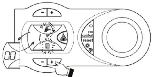
4.Modify the parameter for the type of gas:
-put the boiler in standby mode
press the DHW buttons details 1 and 2 - fig. = 1 for 10 seconds: the display shows "b01" flashing.
- press the DHW buttons details 1 and 2 - fig. 1) to set parameter 00 (for operation with natural gas) or 01 (for operation with LPG).
press the DHW buttons details 1 and 2 - fig. = 1 for 10 seconds.
- the boiler will return to standby mode
- Adjust the minimum and maximum pressures at the burner (ref. relevant paragraph), setting the values given in the technical data table for the type of gas used
- Apply the sticker, contained in the conversion kit, near the data plate as proof of the conversion.
TEST mode activation
Press the heating buttons (detail 3 - fig. = 1) together for 5 seconds to activate the TEST mode. The boiler lights at the maximum heating power set as described in the following section.
The heating and DHW symbols (fig. = 14 ) flash on the display; the heating power will appear alongside.
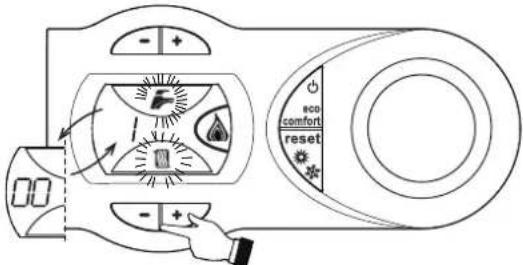
fig. 14 - TEST mode (heating power = 100%)
Press the heating buttons (details 3 and 4 - fig. = 1) to increase or decrease the power (Min. = 0%, Max. = 100%).
If the TEST mode is activated and enough hot water is drawn to activate the DHW mode, the boiler remains in TEST mode but the 3-way valve goes to DHW.
To deactivate the TEST mode, press the heating buttons (details 3 and 4 - fig. =1) together for 5 seconds.
The TEST mode is automatically deactivated in any case after 15 minutes or on stopping of hot water drawing (if enough hot water has been drawn to activate the DHW mode).
Adjustment of pressure at the burner
Since this unit has flame modulation, there are two fixed pressure values: the minimum and maximum, which must be those given in the technical data table according to the type of gas.
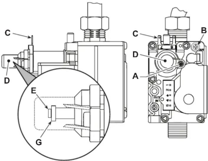
- Connect a suitable pressure gauge to pressure point "B" located downstream of the gas valve
- Remove the protection cap "D" undoing screw "A".
· = OperatetheboilerinTESTmode
= Adjust the power to the max. value. - Adjust the max. pressure with screw "G", clockwise to increase the pressure and anticlockwise to decrease it
- Disconnect one of the two Faston connectors from the modureg "C" on the gas valve.
- Adjust the min. pressure with screw "E", clockwise to decrease the pressure and anticlockwise to increase it.
Reconnect the Faston connector detached from the modureg on the gas valve.
= Check that the maximum pressure has not changed.
· = Refit protection cap "D"
To end the TEST mode repeat the activation sequence or wait 15 minutes.
After checking or adjusting the pressure, make sure to seal the adjustment screw with paint or a specific seal.
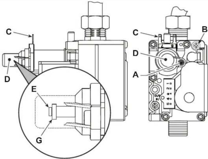
fig.15-Gas valve
A - Protection cap screw
B - Pressure point downstream
C - Modureg cable
D - Protection cap
E - Min, pressure adjustment
G - Max. pressure adjustment
Heating power adjustment
To adjust the heating power, switch the boiler to TEST mode (see sec. =4.1). Press the heating buttons detail 3 - fig. =1 to increase or decrease the power (min. = 00 - max. = 100). Press the reset button within 5 seconds and the max. power will remain that just set. Exit TEST mode (see sec. =4.1).
Lighting power adjustment
To adjust the lighting power, switch the boiler to TEST mode (see sec. = 4.1). Press the DHW buttons (detail 1 - fig. = 1) to increase or decrease the power (min. = 00 - max. = 60). Press the reset button within 5 seconds and the lighting power will remain that just set. Exit TEST mode (see sec. = 4.1).
4.2 Startup
Before lighting the boiler
-Check the seal of the gas system.
-Check correct prefilling of the expansion tank.
= Fill the water system and make sure all air contained in the boiler and the system has been vented.
Make sure there are no water leaks in the system, DHW circuits, connections or boiler.
- Check correct connection of the electrical system and efficiency of the earthing system.
= Make sure the gas pressure for heating is that required.
Make sure there are no flammable liquids or materials in the immediate vicinity of the boiler
Checks during operation
Switch the unit on.
-Check the tightness of the fuel circuit and water systems.
- Check the efficiency of the flue and air/fume ducts while the boiler is working.
Make sure the water is circulating properly between the boiler and the systems.
Make sure the gas valve modulates correctly in the heating and domestic hot water production stages.
Check correct boiler lighting by performing various tests, turning it on and off with the room thermostat or remote control.
= Make sure the fuel consumption indicated on the meter matches that given in the technical data table in cap. 5.
Make sure that with no demand for heating, the burner lights correctly on opening a hot water tap. Check that in heating mode, on opening a hot water tap, the heating circulating pump stops and there is regular production of hot water.
Make sure the parameters are programmed correctly and carry out any required customisation (compensation curve, power, temperatures, etc.).
4.3 Maintenance
Periodical Inspection
To ensure proper operation of the unit over time, have qualified personnel carry out a yearly inspection, providing for the following checks:
- The control and safety devices (gas valve, flow switch, thermostats, etc.) must function correctly.
- The fume exhaust circuit must be perfectly efficient. (Sealed chamber boiler: fan, pressure switch, etc. - The sealed chamber must be tight: seals, cable glands, etc.) (Open chamber boiler: anti-backflow device, fume thermostat, etc.)
The air/fume terminal and ducts must be free of obstructions and leaks - The burner and exchanger must be clean and free of deposits. Do not use chemical products or wire brushes to clean.
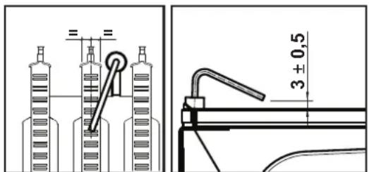
The electrode must be properly positioned and free of deposits.
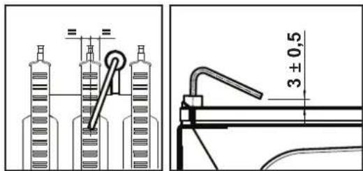
fig. 16 - Electrode positioning
The gas and water systems must be tight.
The pressure of the water in the system when cold must be approx. 1 bar; otherwise, bring it to that value.
- The circulating pump must not be blocked.
The expansion tank must be filled
- The gas flow and pressure must match that given in the respective tables.
4.4 Troubleshooting
Diagnostics
The boiler is equipped with an advanced self-diagnosis system. In case of a boiler fault, the display will flash together with the fault symbol (detail 11 - fig. 1) indicating the fault code.
There are faults that cause permanent shutdown (marked with the letter "A"): to restore operation, press the RESET button (detail 6 - fig. 1) for 1 second or RESET on the optional remote timer control if installed; if the boiler fails to start, it is necessary to eliminate the fault.
Faults marked with the letter "F" cause temporary shutdowns that are automatically reset as soon as the value returns within the boiler's normal working range.
Table of faults
Table. 8 - List of faults
| Fault code | Faults Possible cause Cure | ||
| A01 | No burner ignition | No gas | Check the regular gas flow to the boiler and that the air has been eliminated from the pipes |
| Ignition/detection electrode fault | Check the wiring of the electrode and that it is correctly positioned and free of any deposits | ||
| Faulty gas valve | Check the gas valve and replace it if necessary | ||
| Ignition power too low Adjust Excessive condensate level | the ignition power Empty / clean the trap | ||
| A02 | Flame present signal with burner off | Electrode fault | Check the ionisation electrode wiring |
| Card fault Check the card | |||
| A03 | Overtemperature protection intervention | Heating sensor damaged | Check the correct positioning and operation of the heating sensor |
| No water circulation in the system | Check the circulating pump | ||
| Air in the system Vent the system | |||
| Safety thermostat interven- tion | Check safety thermostat operation | ||
| F04 | Card parameter fault | Wrong card parameter setting | Check the card parameter and modify it if necessary |
| Fault code | Faults | Possible cause Cure | |
| F05 | Air pressure switch (fails to close contacts within 20 sec. of fan activation) | Air pressure switch contact open | Check the pressure switch / Fan / Fan socket |
| Faulty air pressure switch wiring | Check the wiring | ||
| Wrong baffle Make sure the baffle is correct | |||
| Flue obstructed or not correctly sized | Check the length of the flues / Clean the flues | ||
| Air pressure switch (fails to close contacts within 20 sec. of fan activation) due to activation of the fume thermostat | Exchangers dirty (clogged on water side) | Clean the exchangers | |
| Faulty water circulation | |||
| A06 | No flame after the ignition phase | Low pressure in the gas system | Check the gas pressure |
| Burner minimum pressure setting | Check the gas pressures | ||
| F07 | Air pressure switch (contacts closed on activation of fan) | Air pressure switch contact open | Check the pressure switch / Fan / Fan socket |
| Faulty air pressure switch wiring | Check the wiring | ||
| Wrong baffle Make sure the baffle is correct | |||
| Flue obstructed or not correctly sized | Check the length of the flues / Clean the flues | ||
| A09 | Gas valve fault | Wiring disconnected Check the wiring | |
| Faulty gas valve | Check the gas valve and replace it if necessary | ||
| F10 | Delivery sensor fault | Sensor damaged | Check the wiring or replace the sensor |
| Wiring shorted | |||
| Wiring disconnected | |||
| F11 | DHW sensor fault | Sensor damaged | Check the wiring or replace the sensor |
| Wiring shorted | |||
| Wiring disconnected | |||
| A15 | Air pressure switch (fails to close contacts within 20 sec. of fan activation) | Fault F05 generated 5 times in the last 24 hours | See fault F05 |
| A16 | Gas valve fault | Wiring disconnected Check the wiring | |
| Faulty gas valve | Check the gas valve and replace it if necessary | ||
| A23 | Card parameter fault | Wrong card parameter setting | Check the card parameter and modify it if necessary |
| A24 | Card parameter fault | Wrong card parameter setting | Check the card parameter and modify it if necessary |
| F34 | Supply voltage under 140VAC | Electric mains trouble | Check the electrical system |
| F35 | Faulty mains frequency | Electric mains trouble | Check the electrical system |
| F37 | Incorrect system water pressure | Pressure too low | Fill the system |
| Water pressure switch damaged or not connected | Check the sensor | ||
| F43 | Exchanger protection intervention | No system H2O circulation | Check the circulating pump |
| Air in the system Vent the system | |||
| F50 | Controller DBM32 fault | Controller DBM32 internal error | Check the earth connection and replace the controller if necessary. |
| F51 | Controller DBM32 fault | Controller DBM32 internal error | Check the earth connection and replace the controller if necessary. |
5. TECHNICAL DATA AND CHARACTERISTICS
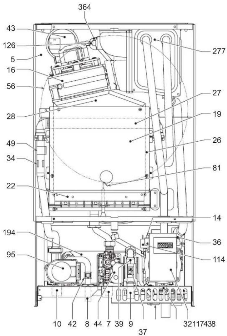
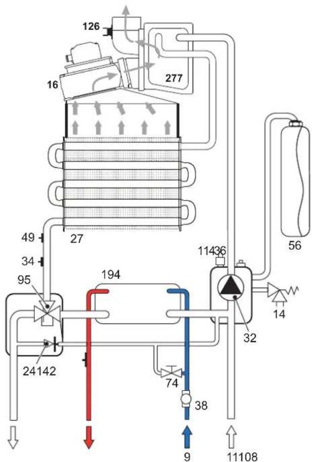
Table. 9 - Key fig. 19, fig. 21, fig. 22 and fig. 23
| 5 | Sealed chamber | 37 | Cold water inlet filter |
| 7 | Gas inlet Ø 1/2" | 38 | Flow switch |
| 8 | Domestic hot water outlet Ø 1/2" | 39 | Water flow limiter |
| 9 | Cold water inlet Ø 1/2" | 40 | DHW temperature sensor |
| 10 | System delivery Ø 3/4" | 41 | Air pressure switch |
| 11 | System return Ø 3/4" | 42 | Gas valve |
| 14 | Safety valve | 43 | Air pressure switch |
| 16 | Fan | 44 | Gas valve |
| 19 | Combustion chamber | 45 | Safety thermostat |
| 22 | Burner | 46 | Expansion tank |
| 27 | Copper exchanger for heating and hot water | 47 | System filling cock |
| 28 | Fume manifold | 48 | Ignition and detection electrode |
| 29 | Fume outlet manifold | 49 | Divertizer valve |
| 32 | Heating circulating pump | 50 | Water pressure switch |
| 34 | Heating temperature sensor | 51 | Fume baffle |
| 36 | Automatic air vent | 52 | DHW bypass |
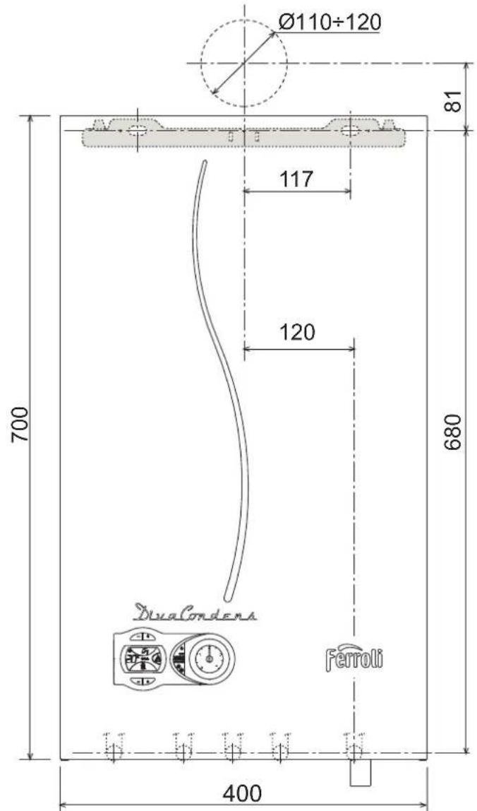
5.1 Dimensions and connections
fig.17-Front view
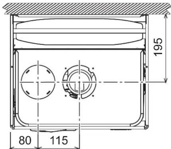
fig. 18 - Top view

fig. 19 - Bottom view
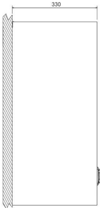
fig.20-Side view
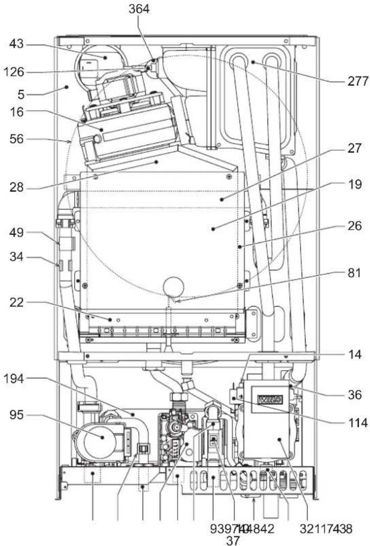
5.2 General view and main components
fig.21 - General view
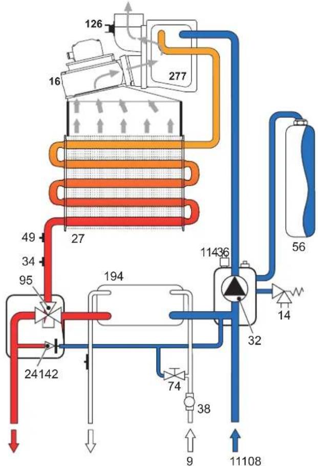
5.3 Hydraulic circuit
fig.22 - Heating circuit
| Data Unit DIAcondens F24 DIAcondens F28 | ||||
| Max. heating capacity kW 25.0 28.0 (Q) | ||||
| Min. heating capacity kW 10.0 10.0 (Q) | ||||
| Max. Heat Output in heating (80/60°C) kW 24.1 27 | (P) | |||
| Min. Heat Output in heating (80/60°C) | kW | 9.2 | 9.2 | (P) |
| Max. Heat Output in heating (50/30°C) kW 25.9 29 | ||||
| Min. Heat Output in heating (50/30°C) | kW | 9.6 | 9.6 | |
| Efficiency Pmax (80-60°C) | % | 96.5 96.5 | ||
| Efficiency Pmin (80-60°C) | % | 92.0 92.0 | ||
| Efficiency Pmax (50-30°C) | % | 103.5 | 103.5 | |
| Efficiency Pmin (50-30°C) | % | 96.0 96.0 | ||
| Efficiency 30% | % | 100.2 | 100.2 | |
| Burner nozzles G20 | n° x Φ | 11 x 1.35 | 11 x 1.35 | |
| Gas supply pressure G20 | mbar | 20 | 20 | |
| Max. pressure at burner G20 | mbar | 11 | 14 | |
| Min. pressure at burner G20 | mbar | 2 | 2 | |
| Max. gas delivery G20 | m³/h | 2.64 2.96 | ||
| Min. gas delivery G20 | m³/h | 1.06 1.06 | ||
| Burner nozzles G31 | n° x Φ | 11 x 0.82 | 11 x 0.82 | |
| Gas supply pressure G31 | mbar | 37 | 37 | |
| Max. pressure at burner G31 | mbar | 29 | 35 | |
| Min. pressure at burner G31 | mbar | 5 | 5 | |
| Max. gas delivery G31 | kg/h | 1.96 2.19 | ||
| Min. gas delivery G31 | kg/h | 0.78 0.78 | ||
| Efficiency class Directive 92/42 EEC | - | ★★★★★ | ||
| NOx emission class | - | 3 | 3 | (NOx) |
| Max. working pressure in heating | bar | 3 | 3 | (PMS) |
| Min. working pressure in heating | bar | 0.8 | 0.8 | |
| Max. heating temperature | °C | 90 | 90 | (lmax) |
| Heating water content | litres | 1.5 | 1.5 | |
| Heating expansion tank capacity | litres | 8 | 8 | |
| Heating expansion tank prefilling pressure | bar | 1 | 1 | |
| Max. working pressure in hot water production | bar | 9 | 9 | (PMW) |
| Min. working pressure in hot water production | bar | 0.25 0.25 | ||
| DHW flow rate Dt: 25°C | l/min | 14 15.7 | ||
| DHW flow rate Dt: 30°C | l/min | 11.6 | 13.0 | |
| Protection rating | IP | X5D X5D | ||
| Power supply voltage | V/Hz | 230V/50Hz 230V | 50Hz | |
| Electrical power input | W | 95 | 110 | |
| Empty weight | kg | 35 | 35 | |
| Type of unit | C12-C22-C32-C42-C52-C62-C72-C82B22-B32 | |||
| PIN CE | 0461CP1030 | |||
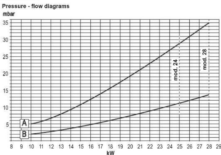
A = LPG - B = NATURAL GAS
Circulating pump head / pressure losses
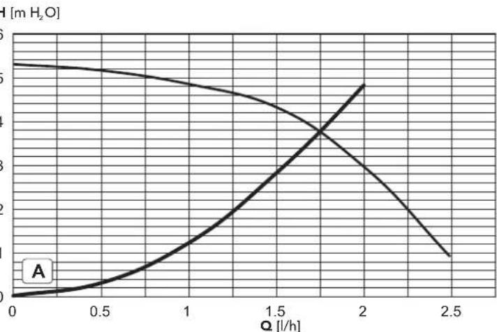
A = Boiler pressure losses
| Trademark: FERROLI | Model: DIVACONDENS FIU | |||
| Address: ☐ RRO S p ☐via Ritonda ☐ ☐ ☐ ☐ ☐ ☐ ☐ ☐ ☐ ☐ ☐ ☐ ☐ ☐ ☐ ☐ ☐ ☐ ☐ ☐ ☐ ☐ ☐ ☐ ☐ ☐ ☐ ☐ ☐ ☐ ☐ ☐ ☐ ☐ ☐ ☐ ☐ ☐ ☐ ☐ ☐ ☐ ☐ ☐ ☐ ☐ ☐ ☐ ☐ ☐ ☓ | ||||
| Condensing boiler: Y.S.NO.NO | Low-temperature boiler (*) | B1 Boiler. | ||
| Combination heater: Y.S.NO | Cogeneration space heater: | |||
| Item | Symbol | Unit | Value | |
| Seasonal space heating energy efficiency class | ||||
| Rated heat output | Pn | kW | mT | |
| Seasonal space heating energy efficiency | ηs | % | mT | |
| Useful heat out put | ||||
| Useful heat output at rated heat output and high-temperature regime (*) | P4 | kW | mT | |
| Useful heat output at 30% of rated heat output and low-temperature regime (*) | P1 | kW | mT | |
| Useful efficiency | ||||
| Useful efficiency at rated heat output and high-temperature regime (*) | ηd | % | mT | |
| Useful efficiency at 30% of rated heat output and low-temperature regime (*) | ηi | % | mT | |
| Auxiliary electricity consumption | ||||
| At full load | emax | kW | mT | |
| At part load | elmin | kW | mT | |
| In standby mode | PSB | kW | mT | |
| Other items | ||||
| Standby heat loss | Pstby | kW | mT | |
| Ignition burner power consumption | Pign | kW | mT | |
| Annual energy consumption | QHE | GJ | mT | |
| Sound power level | LWA | dB | mT | |
| Emissions of nitrogen oxides | NOx | mg/kWh | mT | |
| For combination heaters | ||||
| Declared load profile | X | |||
| Water heating energy efficiency class | ||||
| Daily electricity consumption | Qelec | kWh | mT | |
| Annual electricity consumption | AEC | kWh | mT | |
| Water heating energy efficiency | ηwb | % | mT | |
| Daily fuel consumption | Qfuel | kWh | mT | |
| Annual fuel consumption | AFC | GJ | mT | |
| Trademark: FERROLI | Model: DIVACONDENS FIU | |||
| Address: ☐ RRO S p ☐via Ritonda ☐ ☐ ☐ ☐ ☐ ☐ ☐ ☐ ☐ ☐ ☐ ☐ ☐ ☐ ☐ ☐ ☐ ☐ ☐ ☐ ☐ ☐ ☐ ☐ ☐ ☐ ☐ ☐ ☐ ☐ ☐ ☐ ☐ ☐ ☐ ☐ ☐ ☐ ☐ ☐ ☐ ☽ | ||||
| Condensing boiler: Y.S.NO.NO | Low-temperature boiler (*) | B1 Boiler. | ||
| Combination heater: Y.S.NO | Cogeneration space heater: | |||
| Item | Symbol | Unit | Value | |
| Seasonal space heating energy efficiency class | ||||
| Rated heat output | Pn | kW | mT | |
| Seasonal space heating energy efficiency | ηS | % | mT | |
| Useful heat out put | ||||
| Useful heat output at rated heat output and high-temperature regime (*) | P4 | kW | mT | |
| Useful heat output at 30% of rated heat output and low-temperature regime (*) | P1 | kW | mT | |
| Useful efficiency | ||||
| Useful efficiency at rated heat output and high-temperate regime (*) | ηd | % | mT | |
| Useful efficiency at 30% of rated heat output and low-temperature regime (*) | ηi | % | mT | |
| Auxiliary electricity consumption | ||||
| At full load | emax | kW | mT | |
| At part load | elmin | kW | mT | |
| In standby mode | PSB | kW | mT T | |
| Other items | ||||
| Standby heat loss | Pstby | kW | mT | |
| Ignition burner power consumption | Pign | kW | mT | |
| Annual energy consumption | QHE | GJ | mT | |
| Sound power level | LWA | dB | mT | |
| Emissions of nitrogen oxides | NOx | mg/kWh | mT | |
| Fer combination heaters | ||||
| Declared load profile | X | |||
| Water heating energy efficiency class | ||||
| Daily electricity consumption | Qelec | kWh | mT | |
| Annual electricity consumption | AEC | kWh | mT | |
| Water heating energy efficiency | ηwb | % | mT | |
| Daily fuel consumption | Qfuel | kWh | mT | |
| Annual fuel consumptions | AFC | GJ | mT | |
() High-temperature regime means 60°C return temperature at heater inlet and 80°C feed temperature at heater outlet.
(*) Low temperature means for condensing boilers 30°C for low-temperature boilers 37°C and for other heaters 50 -c return temperature (at heater inlet).

fig. 24 - Wiring diagram

Attention: Remove the jumper on the terminal block before connecting the room thermostat or remote timer control.
16 Fan
32 Heating circulating pump
34 C.H. flow temperature sensor
38 Flowswitch
42 DHW temperature sensor
43 Air pressure switch
44 Gas valve
47 Modureg
49 Overheat cut-off thermostat
72 Room thermostat (not fitted)
81 Ignition and detection electrode
95 Diverting valve
114 Water pressure switch
126 Contact fume thermostat
139 Remote timer control (not fitted)
193 Trap
FR
1. DISPOSITIONS GÉNÉRALES
Selection Eco/Comfort
3.4 Raccordement gaz
2.3 BkIIOyehne N BblKIOyehne
IopKIOUeyHe K cETn 3NEKtpONtAHm
B TEUYHNE 5 CeyHKHa ND AaCnIe 5 dyET BbCBeHabatcBepca NporpAMMHORO 06eCNHeHHN, YCTAHOBENHORO B NEKTOPOHNHO 6IOke.
OTKpoTe ra3OBbI BEHTnIb, yCTaHOBneHHbI nepeD KOTnOM.
TenebKOTIOTOBKATOMaTHeCKOMYBKNIOHEnIO npKAXDDaOpe ropraey B0dy INPn NOCTyIeHNCHINHA HBAIOHeHNE CNTeMeBtOtonneHn (OT KOMATHORTOPEMOCTATA NUNYCTPONCTBA DYCA TaimepmE).
Bknoyehne n Bbiknoeyehne kOtna
Haxmte KhoNkY BKn/BbKn (no3.7-pnc.1)B TeueHne 5 cekyHd.

PNC.2-BbIKIOUeHHeKOTnA
Korda koter BkIOHcTcA, 3NkTpueckoe nTuAHne BCE uee NOCTyNAET Ha 3NkTPOHHy nATy. He pa6oTahOT CnTeMa TBC I ONTONHeM. OCTaETCAKTHBHO CnCTema npOTB ONEHEHIN. YTObbl CHOBA BKIOUHTb KOTen, HAKMITE NOBTOPO HA KHONY BKN/BBKl (no3.7 PmC.1) B TEeHMe 5 CEkyHd.
pnc.3
3TMM 06cneuBaeTcH HeMeDnEHHa rTOBHOCTb KOTNa Ka6ote KaKdbpa3 npn Notpe6bnHrnpRyeh BoDy nn npn 3AnpoCe H OtonneNe (Bb3bAeBMKOMHaTHbM TepMOCTaTOM nn NdCTAHUONHbM TepMOCTaTOM C TaImePOM).
Pn OTKIOUeHn KOTnO TcCTeMb 3NEKTPoNtAHn H/INI RA3OBMAMACPTAN PfHKnnpOTMB ONeDEHnO BTIOHOAETCB.BoBPEMNITENHORO HCNTOB3oBAHNOKOTNA B3MNHNepNoD,BO I6EkaHneyuepeBa OT BO3MOXHO R3aMeP3AHn PEKOMEHdyTeC nTb Bc0 BOYu nKOTnKAk N3 KOHTpyo OTONHEN,TAK IN3 KOHTpya FBC;INN Xe CNTbTONkoBODY IN3 KOHTpya BC INoDBabNTb AHTNpRn B CnCTeMy OTONHeN,B COOTBETCBN C YKAZAAHNM,NPBBeDEHBMn B SEZ.3.3
2.4 Perynnipobknu
IpeeknoueHne pexmOB "JTeTo"/"3nMa"
Haxmte KhoNky "Jeroo""3Ma" (no3.6-pnc.1) Ha 2 cekyHdbI
Ha dncnnee BbcBentc CmBON "Neto" (no3. 10 - puc. 1): Pnp 3tOM KOteIe 6yTeB bpaabaBbTaTo bko body nra IBC. Octaetc aKTHBHO CNTema aHTH3amep3AHNA.
Дя Вьклоченя рекиma "Лето" BHOБь HAXMITE KONKY "Лето"/"3нма" (no3.6 - pnc.1)Ha 2 cekyHdbi
Perynnpobka TempepatbI BObl B CnCTeMe OToJIeHn
C NOMOUSBOHNOKONCTEMBb OTONNEHIN (no3.34 - pnc.1) TEmnepaTypy MOKHO perynipobTaB OT MmHMmaBhoH 30°C Do MaKcMmaBhoH 80°C; He peKoMeHdyetca 3anyckatb KOTEN B paB0ty npT EmnpaType HKe 45°C.
PNC.4
PerynpobKa temepaTyb B cnctme roprero bdocha6xhenra (TBC)
C NOMOJIbIO KHOIOK CnCTeMbI TBC (noa.1 n 2 - pnc.1) TEMpepatyp MOXHOpeyINPOBaTb OT MNHIMaJIbHO40°C do MAKcIMaJIbHO55°C.
pnc.5
PerynpobKa TemnepaTpyb Bo3dyxa B NOMeHNN (C NOMOuBIO ONUOHHO TepMOCTATA TEMNepaTpyb B NOMeHNN)
3aaiTe C NOMObTO TepMOCTaTATEMNEpATypbBOzdyxaB NOMEeHn HkyHyIO TMNEpatpy BHTpyNOMeEHN.IPi OTCyTCTBNI TEPMOCTATA TMEpATpyb BOzdyxa B NOMEeHnKOTEN ObcneuMaET NOdEprXaHMe B CNTeMe OTONHeHn 3aahHOI TEMpeATpy BoDJI.
PerynnpOBKa TemnepaTypbI BO3dyxa B NOMeueHNN (C NOMOsbIO ONUHOHHOR yctpoiCTBa Dc TaMepoM)
3aaiTe c nomoubIy yctpoNCTBa DY C TaMepOM HxHyIO TemnepaTyP BHyTPO NOMEHIN. KToEN 6yET NOdEpxNtBb TEMnepATpy BObl B CNCTMe, Heo6xOAnMyIO DnB ocepeHEnB N omeuHIN 3aHaHHO TEMnepATpy Bo3dyxa. B TOM, CTOKaCaETcRa 60TbA c yCtpoNCTBOM DY C TaMepOM, CM COOTBECTByUOy IHCTPyKUHO HA 3TO YcTPOINCTBO.
Bb6oppeKmOBECO/COMFORT
KoTeIobopyoBaan CneuaHbNof yKnuee, ObecneuBaOuee BbcOkyo ckOpocTb noaHBObl B cnteME IBC n MaKcImaHbHbKOMpOPT dnaonb3OBaTeNIA. KOrda 30 yctpoiCTBO 3aedCTBOaHO (peXmM COMFORT), OHO noDaepeKHaET Temnepatypy haoJaIeBcB KOte BObl, ObecneuBaA TEM cambIM HeMeJeHHoe NoctynHe HorepaHn Eoo6xOIOMOCTb JDaTb 3TORE HEKOTOPoe Bpemr.
JaHHeO yctpoiCTBO MOKet 6bIb OTKnIOUeHO NOIb3OBaTeNEM (peXHM ECO), HaxaB KnaBIy Eco/comfort (no3.7 - pnc.1).PmP a60te B peXMME ECO HA cnsnee BBcIEHbAeTc COOTBeTcByIOUc CMBON (no3.12 - pnc.1).DnRA BKIOUeHry peXHMA "KOMΦOPT"CHOBA HxMnTE KHOKNY "3KoHOMuHn""KOMΦPT"(no3.7 - pnc.1).
PerynpoBaHne c dNCTaHcUHOHHoro nyIbTa ynpaBHeHra c TaMepom
Ecnn K KOtny nOdkIIOHyo YcTPOIACTBO DuctAHUHOHOY npaBNEHn C TaIMePOM (OnuH), BIIeONCAnHHe peyINpOBKn npo3BOrTcB COOTBETCBN cKyaAHHMn, npRBeDEHNbMn B tabNIu 1.
Tabnua.1
| Peyrnapokbka TemnepatypbI b OboI b CNTeMe OTONHENIA | Peyrnapokbky MoKHO ocUyecBTLaTb KaC uepe3 MeHIO NpIbTa Dc TaimePOM, TAK c N pAnHeNl UynpaBtenHIN KOTNA. |
| Peyrnapokbka TemnepatypbI b CNTeMe ropJraTe BOODsHbEHNIA (TBC) | Peyrnapokbky MoKHO ocUyecBTLaTb KaC uepe3 MeHIO NpIbTa Dc TaimePOM, TAK c N pAnHeNl UynpaBtenHIN KOTNA. |
| PteKHeNoHene peXeHIMOB "JIeTo"/ "3MMA" | PexHIM "JIeTo" obIpaDAET npInOpHTetOM HAD KOMAnDoN Ha BKNIOHEnIE OTONHENIA, KOTOPAR MOKeT NOctyrnITb OT pIbTa Dc TaimePOM. |
| BbIbop pexHIMOB "3KOHOMNUHbI" "/ "KOMΦOPT" | BbIbop XeHaEMOrO peXeHIMa MOKET ocUyecBTLaTb cOnIbTa c TaimePOM. |
Perynpobka daBneHnBaOdbicnteMe
DabnHeHne Hanopa np3anOnHeHHXoONHOrO KOHTpya, CunTaHHeo rnpomTePOM KOTna(No3.17 - PmC.1.DonKTHOcCTABNtB np6nHNTbHO 1.6Bap.Ecn BO pBemPAbaTbI daJIHeHNE BODB I CHTeME ynAETDe BOENHbH NHXKe MNHMAnBo DOyctIMoN, KOteJ 5dyet OcaHOBHeN Hua DCnnee BbcBeITcN OuHbKa F37.C NOMOuHo KpHa DnA 3aNNBKn BODbl (No3.1PmC.6) DoBeCTn DaJIHeHne Do nepBOHauehBHO 3HaueHn. No OKOHauHHonepaun BCerda 3akpbBaIne Kpan 3aNNBKn BODbl.
Pnc.6-KpaH 3anolHeHHKoTna
3. MOHTAX
3.1 yka3aHn8 o6uero xapaKTepa
YCTAHOBKA HACTPOIKA FOPEKNI DOJIKHA OCUJECTBJIATbCR TOJbKO CNEUAMN3HPOBAHNbIM NEPCOHANIOM IMEIOUIM NPOBEPEHNHYO KBAJNFOKALIO, PN CO5NJIOJEHMN PIPBEDEHHbIX B HACTORIEM TEXHNUECKOM PYKOBODCTBE YKA3AHIN, PNEIINCAHIN DECTBYUUEFO 3AKOHODATEJBcTBIA, NOJOXEHN MECTHBIX HOPM IN PABIN, IN COOTBETCTBNI C PPNHRTbIMN TEXHNUECKIMN TPEBOAHNRMI.
3.2 Mecto yctahOBKu
Kamepa cropania arperata repmetnno H30nnpobaa H0THOCHTeBHO nOmeHnna NO3OTMY OH MOKET NcNtB3OBaTbCBA JIO6OM NOMEUHIN. Tem He MeHe NOMEUHNE, B KOTOPM YCTAHNBNAETCR KOEN, DOnkXHO IMeTb DOCTATOHYBO BEHTNNIuO DnA npEDOTBpauHEn OANcbHs CUYaun B CUYaue XOTb 6bl MabIb yTeueK r3a. 3Ta HopMa 6e3onacCHTOpeDyCMTOpe HINepKTbOB CEE No 2009/142 dN TCEPABTOUHX Ha r3ae arperatOB, B TOM cncne I dN TAK HA3bBaembIX arperatoB C 3akpbToK KAMEPOI.
Annapat MOKET paObaTbB YaCTMnHO 3auuHHeHHOM MeCTe, cOrnaCHO CTAHapTy EN 297 pr A6, npi TmepaType -5°C. PeKMeHdyTec yTaHOBHT b KOte nKD KatOM KpbIur BHYTpBANKHO Hnn 3auuHHeHH NHI.
B IIO60 cmIyae, B MecTe yCTaHOBKn He DoNkHbI HaxOuTbCra Nblb, orHeonacHbI npEIMeTbI nnMATEpuaIbn EKnE ra3bl.
Koten npedHa3HaeH dnoBecn Ha CTehy n noCTabTReTCB KOMNKeTc C noBecbHm kPOHtueHOM. PpIKpENITE KPOHtTeH K CTHe B COOTBeTCTBm C pA3MePAMn, PPNEBEdHeHbMn B Prc. 17, n NOBecbTe H a Hero Koten Kpenne H e KCTHe DOnkHOoM o6eNeuBaTB CTaBnBHOCT bnpOHOCT NBIOXeHnKOTna.

Ecni arperat yctahabnbae3cpei MeBENI 60KOM KCTHE, CNEyET npedycmOTpeb Cbo6OHDoe npoCTPAHCTBO, He6xOdMIOE dIa DEMOTaKa KOKXya BnblONJIHHeN OBhHbPaobot no TeXbCNYkBAHIMo.
3.3 Hnpabnueckne coeHHeHna
PpeDynpexkdeHn
CnBHOe OTBepCTne npedoxpanHTenbHoro KnaHAna doNkHO 6bIb coeHHeNo CBOPOHKnn CO CNBHOH Tpybo BO n36ExAHme NnHnHn BOdu HnON B cnYae NObSiHEna DaJIeHNs B OTOINbEHOM KOHType. B pOtnBHOM CnYae N3rTOBHTenb KOTNa HE HeCet HNKAKOn OTBETCTBeHHOCTHa 3aTOnNEHe NOMEeHnnpi CpabTaBHaHm npedoxpanHTenbHorO KNAnaH
Ipeed BInonHHeMnokKnIOUeHn CneJeT npOBepNTyOn annpat roTOB dpa BoToCmEIOOcMn TINOMa, noCe IBOe BInONHb TuaTeNbHyO OHCTky BCEx Tpy6oONpOBoD OTONiTEhOB NCTeMbI.
BbINONHnTE NOKIIIOHcHn K COOTBeCTBHyOuMm WTyuepam COrnaCHO epeXy Ha pnc. 19 IN B COOTBeTCTBnC CmmboAMn, mHeouzmmncr Ha camom arperate.
PnmeuHne: arperat OchaueH BHyTpEHHM bainachbIM KnaanHom B CNTMeOTOnJIeHHN.
XapakTeepnKu BOBdIIN CNTeMbOTONneHn
B cnyuae, ecnn jeeKtKoCTb BOnbl npBeBbIaet 25° Fr (1°F = 10 nmm CaCO₃), HcNoB3yEmar BODa DOJIHKA b6Tb HAnDEkAaMm o6pa3OM noDROTOBHeA, TOb6b npEoTBPaATb O6paOABHn AHNKIN B KOTNE.
CnCTema 3aunbIOT 3amep3aHn,KnKne aHTnΦp3bl,do6aBkn n HnRn6ntOpbl
IcnoIb3oBaHHe JxNkXh AHTnDpH3OB, D6abok HnHn5ntOpob pa3peaetcB Cnyae HeO6xoIMOCNT TONKIO N KCNIOHHTeBHO, ECNI XN I9OTOBNTBeJdAET rapAHTHIO, NOtBepKdaOuyko, YTO erO npdyKuOYOBueaET DaHNOMBY dNHy cNoIb3oBaHnHn He pInyHnT BPeDA TENNOOOMeHHNK KOTNA IN DpyfMM KOMNNEKTYUOMM NmHm MATEpNaAM, IcNoIb3oBaHHbIM B KOHCTpyKlMn KOTNA IN CNTEmbl. 3anpeuaTeC nCNOIb3oBaTb XJNDKE AHTnDpM3b, DOABKu N HnHbNtOpbl, He npeHa3aHuEHnle CneauNaHbD nPnPMeHEHn B TENIOBbIX yCTAHOBkX IN HECOBMECTMbE C MATEpNaAMn, IcNoIb3oBaHHbIM M BOHKCTpyKlMn KOTNA IN CNTEmbl OTONNEHnE
3.4 Ra3OBbIe coeHHeHn
TnOdkHouaTcK COOTBcTcByUoMeMy nATpy6ky (cm. pnc. 19) c co5bIooHeHem
DeCTBHyOuHX HOpM, C nCnOJIb3OBAHmE XeCTKO METaJIHueCKO Tpy6bl IIN mR6KORO
WJNAHr N3 HEPXABeHOUs E CTAN Co CnNOuHOI ONNEKo.Mekdy RAoONpOBoDM O
KOTlOM DOJKeH 6blbYcTAHOBJERaOBOy KpaH. PpoBepbTe repMeTuHOCtB CeX
Ra3OBbIX COeIMHeHN.
3.5 ΘeKtpnueckne coeHHHeHna
PpeynpeKdHn
Annapat donKhen 6bIb noKnIOueH K naEHHo CnCTeMe 3aEMHeHna, BblnoJIHeHHO B COOTBETCBN C DeINCTBYOUIMM HOpMaMn TEXHNK 6eONaCHOCT. 300fKeTNIBHOCT b KOHTypa 33aEMHeHn Iero COOTBeCTBNE HOpMaM dnKHHb 6bIb nPOBepHe KBAInuHupOBaHHb m nepcoHaON. N3rOToBtEN He Hecet HAKAOI OTBETCBEHOCTa yUeP6, Moryu nn 6bIb npnuHEHbIM OTCYCTBmE 3aEMHeHna anapata.
BHytpEHnne 3NEKTPnHeckn CoeHnE H B KOTNe yKe BInONHeHb, OH ChA6xkEn TAKKE CTeEBM WHPOM TINa "Y" 6E3 BNKn. NpOKnOHeHn K 3NEKTPnCeCKo CETn DOJNHO 6BtB BInONHeH B INDE PmKcPObAHHORO COeHNHOrO, OOBpyOBaHHORO DByXIOIOCHbIM BIKKIOUaTElem C pACCTOHm EMeKdy KOHTAKTAMn HE MeHee 3 MM. Ha Yactke MekDy KOTJOM nIcTOHKM 3NEKTPnCeCKoro NITAHn DOJNHO 6BtB yCTaHOBnEHn PIIaBKnpeDoxpAHENTn HA CNY TOKa HE 60nee 3 A. PnR BInONHeHn 3NEKTPnCeCKnx CoeHNHeHn OChb BaxHo co6NIOctn NoJIpaHocTb (FA3A: KopuHeBn npoBD / HEITPAJIb: CnHI npoBD / 3EMNr: XeNTo-3eENbH npoBD.
I NpIb3OBaTeIIO 3anpeaaeTcamocToTEnbHO npOn3BDoNTb 3aMeHy Ka6eI IITAHN. B cnyae nobpeXeHnna Ka6eI BbIKIOHTe annapat n 06paauTecb K KBaINnPHuPBOAHbM nePCoHAnOM dner erO 3aMeHb. B cnyae 3aMeHb 3NeKTPueckoro Ka6eI, INcONb3yTe NCKIOHTeNHO Ka6eI b TnIa "HAR H05VV-F" 3x0,75 MM2 cnapyKbIM dAmApTOM He 6oJee 8 MM.
TePMoCTaKOMHaTHOH TemnepaTpybI (onu)

BHIMAHHE:TEPMOCTATKOMHATHOHTEMNEPATybldoJXeHbItb VCTPOICTBOMC KOHTAKTAMNHE NOI HANPRAJEHMI. PNI IIOAue HAPRAXEHH230 B HA KJIEMMbI TEPMOCTATA KOMHATHOH TEMPEPATybl NOBIEUET 3A COBNI HENIOJEXAAEE PEMOTHY IOBPEKDEHHe 3NEKTPOHHOIIATbl.
PnnoKIOHcHnn peryIaTOPOB KOMHaTHOH TemepaTybC NOBpEMHOH nporpaAMMOy npAbaHneHH nn TaMpeHa, He cNepyET a3nBtBbATb INe Ycepe3 pa3MbikaoUe KOHTakTb. B 3ABNCIMOCTOn OT Tnna yCTpoiCTBa NITAHHe DOJHKNOBDIOHcHapMyoOT cTeNnOt Obatapeek.
OcTyK 3NeKtpnuecko KJEMMHO naHenn
CHB8OBUNBYKOTNMOXHO NOJYNUHTBOOCTYN K3NEKTPUeCKOKNEMMHO NAHNNPACNOONKEHEKMMDnPA3NNUHbIX NOKNIHOENINPNBODNTCAKKe H3NEKTPUeCKO XCEME HA PNC.24.
PNC.7-DocTyKKnEMMHOH naHeH
3.6bIMOXOaI
PpeynpeKdenn
DaHHb annapat OTHocnTc K TnHy "C" T.e. K KOtNam c repmetuHoi KaMepo CropaHnI N pInHdyntelHoH TReO.Bo3Dxy03abOp N BbIXoD bIMOBxraOB npCeoHNJHOTC COOTBCTBeHHo K CTmEAM acnHpaUIN N bIMoydaneHn, KOTOpbe DOHNKy UOBDBETBOPTN PInBEDeHHbIM NHE Tpe6OBAHmN AHNB annapat ceTNpHIOPOBaH DnI npImeHHeo Co BcEMN KOHPhrpyaunmN BO3DyXOBOD Cny, Yka3aHHbMM Na TabNIYcK TeHXuecknx DAHHbX. Tem He MeHBe, BO3MOXHO, 7TO npImeHHe HekOTopbIX KOHPhrpyaum OrpaHHVAEcR NIN 3anpeuaTeC MecThbIMN 3aOKHMn, HopMAMn IN npabnnAm. PpeXde Yem npCTynatb K MOHTaxy, BHMaTeBbHO O3HaKOMbTEcB C COOTBCTByOuUMN PpeINCAHmN IN ObecneBte IX CTporoe coBLOJeHn. KpmeTOR, Heo6xoMuOcbMoTaBt npabina, kacaOnuece PaONOnEXHn ORONOBK Bo3DxyOBoB HA CTHe n/nn KpbIe N MHIMAbHBx pacCToHHn OT OKOH, CTEn, dpymX BO3DxyOBoBn T.I.D.
DnaΦparMbI
Ia o ecneHn npablnbHO pa60t b KOtna Heo6xOJMMN HcnoIb3OBatb Noctabnembe B KomnNeke C annapatom dAafparmbl, coBIOdra npBBeHHBe B NHexeCneDyUOINX tabuiax yka3AHnn
Ipeep yctahOBKO tybblDIMOxOda Heo5xOIMO npOBeprHa HnHne HaNNeKauei DnaoparmB (ecnn OHa DOnkHb 6bTB nCnObn30BaHa), a TaKHe npabInbHOCTbe ee yctahOBKn Ha noctabnReMbIX KOTnax yctaHOBneHa dnaOparma HnMaMeHbWero pa3mepa Ipn3aMeHbI dnaOparmB (no3.1-pnc.8) BbINONHTE deNCTBny,ya3aAHhBe B pnc.8.
pnc.8
POncoeHHeHc nOMOuBIO KoAKCNaIbHbIX Tpy6
pnc.9-Ппмерыnpсоeнненс c nomoшьkoakcnaIbHbIXtpy6(= Bo3dyx/→=ДыIMOBIEra3bl)
Ta6nua.2-BapnaHTbI nCnonHeHHa
Ta6nua.4-BapnaHTbI HcnoHHeHH
| Tin | Hann MehoBAnHe |
| C1X | Горозноглные trубы ддprптOKа BCоDAxу и уdANeHЯ DLIMOBx RA3OBчЕрES CTeHу. OToNobKДгд уdANeHЯ DLIMOBx RA3OB uprnITOKA BCоDAxu ДОПКь CBБТКохСКМВЛHOrO TINHA KINU YCTAHOBeHЯ Na HbEONbIOMPACSTOKHMyDpyrOT ODPYRA (He BoJee 50 cm).УТББСИНДОВРAZIC BcDINHOBM BERTPOBIM BOSTDAKCTBMR. |
| C3X | ВерTKANbIHy TRy6I drrprpNOTa BCоDAxu n UdANeHЯ DLIMOBx RA3OBчЕрES KByLBy. OToNobKДгд уdANeHЯ DLIMOBx RA3OB uprnITOKA BCоDAxu KAK Dдг TINA C12 |
| C5X | Горозноглные кдprnERtOKA BCоDAxu n UdANeHЯ DLIMOBx RA3OB uprnITOKA BCоDAxu c ОТRONOKAM, PAcTIONOKeHbIMBA MCTax C pRABHIM. OTeBcPTERd YdANeHЯ DLIMOBx RA3OB и prpNOTa BOvDAxу He DOlKNHb HAXOДТСЯ n protINBOVONTOHbIX CTeHax. |
| C6X | ОТДENbIHy CStCTMBy PrpNOTa BOZDAxu n UdANeHЯ DLIMOBx RA3OB, BbIONINHbHbN bN 3 Trp6 OToBpeHNO TINa (cornNacho STAnDAPrty EN 1856/1) |
| B2X | Збop рprtNOTHOrO BOZDAxu И NOMeUHЯ, Дду yCTaHOBHInn AINapat, n UdANeHЯ DLIMOBx RA3OBчЕрES СTeHу NIN NkPbUy. ΔBHIMAHNE - B NOMEUSEHIM DOnIKHb BAItb PPEYCMOTPEHA 3ФФEKTINBHAR CNTTEMAs BEHTINJIPLIM |
IIN NOCDcoeDInHeHn C NOMOUsbO pa3dEnbHbIX Tpy6 yCTaHOBnTe Ha arperate CneDuOnm CoeMHHTeBHy 3NEMENT:
041064X0
pnc.12-CoeHHntbHbI 3nemtIpa3dneBbIX Tpy6
Ipy npOBepKn toro, He 6yET nn npeBbIeHa MaKcHMaJIbHO dOnyctmna DnHbMbOxOIOB, NpeB BbINONHeHHem MOHTaxa HeoXoDMBO BbINOHITb npocTo paCet:
- OKOHATnelbNo onpeIeNTHe cxmny npoknAkn pa3eIbHbIX BO3dyXOB0DoB, 2. KIOHuaA kceCCyaBpI N BixOxDhJIe TepMInHaJIb.
- B COOTBCTBNiC T aBnIa 6 onpeIeNITE n B m3k (KbMbAneHTbHx Metpax) H Ka KJDM KOMNOHEHT B 3ABNCIMOCTN OT ERO paoNONKHeN
- PpOBePbTe, YTO6bI O6aA BENHINHc CONPOTMBeHINH 6bIa MEHbIe INN paBHOJ MAKCMMaJIbHO DOyNCtHMoB ENHInHe, YKazAHHO B TabJIua 5.
Ta6nua.5-DnaΦpaarmbI Dn pa3DneBbHbX BO3dyxOBOOB
Ta6nua.7-BapnaTbI nCNoHHeHH
| Tin | Hannemanohne |
| C2X | 3a60 prinrTOHoro BOADyxa H ydAneHHe DbIMOBx RA3OB Yepe3 0oum HbIMOXoD. |
| C4X | 3a60 prinrTOHoro BOADyxa H ydAneHHe DbIMOBx RA3OB Yepe3 OTeIeMbHe Ooum He DbIMOXoD, H0 PoiBeprAOuUeCK OIOHAKOBM BETPOBbM BO3OeCTBMnM. |
| C8X | YdAneHHe DbIMOBx RA3OB Yepe3 OTeIeMbH Nm HbOUM BoIMoxoD, 3a60 prinrTOHoro BO3Oyxa Yepe3 OTeBcPTMe B CTBE. |
| B3X | 3a60 prinrTOHoro BOADyxa H3 NOMEseHnE YcTAHOBV Anpapata Yepe3 KoAKChIbH NtpybOpBOoD (BKIIeauKoIz MlbMOCTBDOaYU ToBy) H ydAneHHe DbIMOBx RA3OB Yepe3 OTeIeMbOxoD C ECTeTBENHO TAOI. |
| BHIMAHNE - B POMESEHIN DOJIXHA 5bITb PPEDYCMOTPEHA 3ΦΦEKTNBHAR CNTEMA BEHTINLAQUH |
I03TOMy,ecn Bby XoHTe noDcoEHNHb KOTen DIVAcondens F24/F28 K KOJIENKTHBOMY DblMOXOyIM NK OTDeNbOMy DblMOXOyC cECTeBHNOI TROI, Heo6xOaHbM yCIOBEM RABETCA, YTO6bI 3TN DblMOXOdb 6bIIN CnpoeKTPOBAHbI KBaHΦHUNPOBaHbIMn CNEUANCTAMn B COOTBcTBMn C DeIcTBMyHOpMaMn N IOxOaHbIMn ArperatoB C 3akpItOn KaMepOn cropanH, O6opyoBaHbIX BEHTNlRtOpom.
4. YXOD IN TEXHmECKOE OBCJNYKUBAHME
4.1 PerynipobKu
IpehaetpokaHa npyroTnra3a
Arperat paccHTAH npaBt KaKa Ha metaHe, TaK Ha cKHeHOM HeFTHOM rase. IIOrTOBA KOTn KaPoeT HAM ToH NpyrOa R3aOBOM TOnNIBE PpONBODITcH A3aObe, PnHEM COOTBCTBYUoee YkazAIme PnpBeHO HA ynakOBKe, A taKHe KA TabNtke TEXNHmckx DAHHbX, yctAHOBHeHNO HA CAMOM arpeBa. E Cnyuae Heo6xOIMOCn NepeBoHa KOtNa H aPbOtY C rAOM, OTNNHbM OT rA3a, dNRA KOTopo Ro OH 6bl NaHCTpoEH H 3AOE, Heo6xOdIMO npIOBpCTn CneauAIINo ppeDyCMTopeHbN DnA 3ToH CEIN KOMPiNEKT DnA nepeo6OpoyoDaHn N DEIeTBOBaTb, KAK YK3aHO HIXe:
- OTKIOHHTE 3NEKTPNHECKOE NITAHNE OT KOTNA H 3AKPOITE Ra3OBBb BEHTINb.
- 3aMeHnTe fOpcyHKn Ha rnaBHOr ropEnke, ycTaHabINBaBf opCyHKn, peKoMeHNObaHbHe B TaBnIe C TexNHueckMN DaHHbMn HA cap.5,B 3aBNCIMOCTN OT NcONbSyEMO TnAra3a
- IopaiTe NITaHHe Ha KOTen N OTKpoTRe ra3OBbB BENTINb.
- 3meHeHnepapameTpao0oTBeTcByKUeeroTuynrRa3a:
yCTAHOBNTE KOTEN B pexm OxndaHn
HAKMITE H KONIKI CNTEMBI TBC (no3.1 n 2 - pnc. 1 ha 10 cekynd: Ha DCNPIE BBOBDTCA "B01" MBAUOTOCE COCTOHAYA
HAXMMTE HA KHONKIN CNTEMbI TBC (no3.1 2 -pnc.1, YTO6bI 3a4aTb npapamet00 (Dnpa6oTbHa metaHe) nU 01 (Dnpa6oTb Ha cKXKeHHOM HePTrHom rae GPL).
HAXMNTE HAKONKNCCTEMbI FBC (no3.1n2-pnc.1) B TeueHne 10 ckyHd.
KOTeJI BepHETcB PexIM OxuHaHn
- Otperynnpyte MNHmAbhOe N MAKCMMaBHOe DaBNEHHe Ha ropeJIke (CM. COOTBCTBTOIupnaparpaΦ), 3aBADAB 3HaTHeHn H3 TaBmCuIbTexHmCckHXdAHHbIX DnNcNbEyMORo TnIaRa3a
- Hakneite 3TKKETky, coepkaaykoc B KOMNNEKTE no nepeBODy Ha pyroTn rataa, BO3ne Ta6NHK CTEXHHeCKMn DaHHbIM, YTO6bl NoDTBepNTb COCTOBWHINCR peBOD.
AKTINBaUNrTeTOBOro peKmAs TEST
OndobpemHNO HAXMNTHE KHNKNCCTMEB OTOINNEHNO (no3. 3 - pnc. 1) HA 5 ckyH, QTO6bI BKNHOHTB TECTOBH PEXN TEST. KOten BKNHOHTC HAMKCMANBOH MOUHOCTN, 3aADHOH TAK, KAK YKA3AO H CNeDyIOE M aparpaPe.
Ha dncnnee mraiot cmbonbl otontneHn I TBC (pnc.14); paoom oto6paXaetc Mouhoctb otontneHn.
pnc.14-PexnM TEST (MOUHOCTb CNTeMbI OTONJIeHnR = 100%)
Haxmte Ha KHONK CNTeMbI OTONNEHnna (no3. 3n4 - pnc. 1) dnnyBENHEHn mIyEMbSeHn MOUHOCTH (MHNIMAbHa MOnHOCTb = 00% - MaKcMMaHnMoUHOCTb = 100%).
B cIyHae akTbuaaunpekIma TEST n 3a6opa B0dy fBC,doCTatoHoro dna kTbuaun pekIma TBC, KOten octaetcB pekime TEST, H0 3-xoobon knanan nepeknouaeTcB pekim TBC.
IpyOTKIOHHeHHpeXIMATESTOHOBPeMeHHoHaxMITEHaKHONKnOTOnJIeHHa (no3.3 4-pnc.1)BTceHHe5ckyHd.
PekmTESTBn60mCnyaeABOMATNUeCKNOTKINOHTCYpe31MHyTnHn no 3apeHnem3a6opaBoBbIIBC(BCnyaeecnBeHNuHa36opaDcTOtatoHn daJr actNaBaupeKpMaIBC).
Perynpobka daBleHna ropeIky
3TOT aperat, OTHOUIINCK H TNY C MOnDyNpyEbmM NnameHEm, IMeET DBA fKNCPOBAHHbX 3HAeHEna DABeHNe: MHMNAMBHe NO MCMCnABHe. 3TN 3HAeHEna CNEyET B3YbI I3 TabNtBu TeXNHmecKx DAHNbHX HAOCHe IcONbLYeMORTO HnTA rA3a.
IodknIOHTe MaHOMETp Kpa3bemy dny 3aMePa daBneHn“B”,paCnoN0XeHHOMy Ha BbIXOde n3 rA3OBOro KJIanaHa.
CHMMTe 3aunTHbIKoNNaOK D'OTKpyTNB BNT "A".
3anyCTITE KOTEN B TECTOBOM PEXIME TEST.
- OTPerynnpyTe MaKcImaJIbHyIO MOUHOCt b Ha MaKcImaJIbHOe 3HaueHHe.
- Otperynpyte MaKCHMaHbHoe DaJIeNHe BInHTOM "G", NoOpBaHbBra ero no caboB CTpeKN dIy YBeIuYeHn I npOTb VacBOB CTpeKN - DnY yMeHbJeHn daJIeHn.
- OToCoeDInHnTe OOnH n3 DByx CoeDnHnTeNei OT KAtyUKN peYIpObaHn Modureg "C" Ha ra3OBOM KnanaHe.
- Otperynpyte MMHmMaIbHoe daBHeHne BuHTom "E", nobopauHBa ero no caboBtpeIKn dny yBEnuHHeHn npOTb HacBOBt CTePkn -dny yMehbWeHn daBHeNn.
IocoeHNHTe coeHNHTb,pahee cHtBcKatyuKperynnpoBaHm Modureg, Ha ra3OBbl klnanH.
Y6eNTecb, YTO MAKcMaJIbHOe DaBHeHHe H3MeHINOCb
BepHnTe Ha MeCTo 3aunTHbI KOnnauK "D",
Дязавершени TeToBOrO peKIMa TEST noBToPte npoueDpy akTnBaunm nIIN noDoXdTe 15 MInHy.

Pocne npoBepKn daBnHn Hnn erO peryNIOBKN Heo6xOIMO 3aneaTaTb Kpackon nncn cneuaNbHo neaTbO perynpoBOHbI BNT.
pnc.15-Γa30bI KπaNaH
A-BnHT3aunTHbIKoNNaOH
B-Pa3bem nna 3amepa daBneHnHa BbIXOe nKlaNaHa
C-PpoBcKaTuKn peryu npOBaHm Modureg
D-3aunTHbIKoNnaHOK
E-PerynnpOBKa MHHMaJIbHOrO daJIeHnR
G-PerynnpOBKa MaKcImaNbHoro DaBHeHr
PerynpoBka MouchoNt OToJIeHn
Дяретуларьк moшостс nToOnнeHЯ yctahOBHTe KOTe B peKIM TEST (cM.
sez.4.1).Haximmaite kHONK 3aDAHnI TEmpepaTybl BObl B CNTeMe OToNIneHnI (no3.
3 - pmc.1)Дг cooTBETCTBEHHORO yBENmEHN I Nm IyMeHsEHN MOnHOctn
(MMHmAbha=00/MakCmAbha=100).Pn Haxatnn B TeeyHe 5 ckyHn NocJI
3TOrK KNK "CBPCO"coxpaHntc TOnbKO YTO 3aDAHnA MaKCMMaNbHaM OMOHOCtB.
BbuiDte n3 peKIMa TEST (cm.sez.4.1).
PerynpobkAMoHocnpo3knra
4.2 BbOaB 3KcNpyTaumHO
IpepeBknHcHEmKOTna
PpOBepeTepemTeHHOCTbCNCTeMbI NOBDAra3a.
PpOBeBpTe npabInbHocTb npeBaPteNbHO c03daHHoro BpacuPntbHom cocyde daBHeHnA.
3aONNHte CICTeMy BOIOI IO NNOHCTbO CNyCTHe BO3dyX I3 KOTJI a NCTeMb1 OTONNEHIN.
UdoTbBcBbCTbBcYtCBTNbYteKBCbIbN3CtEbMbOTONNEH, KOHTpya IBC, NKTOnBaN3yBcHbXbCOeDHHHEHX.
- PnpOBeBte npABHbHOCTB bINONHeNr 3eKTPnEeCKnx COeHNHeH N 3ΦΦeKTHBHOCTb 3A3MEnHeNr.
- YdoCTOBepTecb, TTO BENmHnA daBnEHHra3a COOTBECTBYOT Tpe6yEMOMY 3hauHEnIO.
PpOBeBpTe,TO B HENOCpeDCTBEHHoB 6JIN3OCTN OT KOTNa HE HAXOJaTcR orHeOpAnChIbe XnIKOCTN MATEpHaNbl.
KoHTpOlbHbIe Opeaun, BbINOJIHReMbIe BO BpEmpa60TbI
BknquHte annapat.
PpOBepeTepemTeHocTbTONNBHOKHTypaNBOOnpoBOoB.
Pn pa60taoouem KOTne npoepebte, HopMaIbHO nI pa60taoT DbIMoxOu BO3dyXOBoBbl dIe npitOKa Bc3dyxA uDaneHnN DbIMOBx rA3OB.
- PnpoeBte, npabnIbHO nIuKpynpyet Boda Mexdy KOTnom N CNTeMOI OTONNEHIO.
- UdoctoBepbTecb, yTo ra3OBbI KJIanaH npaBnHbO o6ceNeuBaet MoylaHIO MOUHOCTN, KaB bpeKIMe OTOPHeHNA, TAK N B peKIMe IBC.
IpoBebte pabot cyTcEmbl po3Kmra KOTn. DnT OTO HeCKoBko pa3 BKNHOHTe N BkHIOHTe KOET nyTEM peyINpOBKn KOMHaTHORO TepMOCTa HnC nYbTa DCNTAHNOHORO YNPABNEHNA.
YDOCTOBepbTecb NO NOKa3AHnM CHTyNkA, YTO paCXoJra3a COOTBeTcByET BeHmHe, yKa3aHHoB B Ta6nIe TEXHmecKx DaHHbX B cap. 5.
PpOBeBTe,TO npn OTCyTcBN CnHana Ha BKnIOHeHne OTONHeHna, RopeKa 3aKHaTaCn npn OTKpbTnI NIO6oR KpaHa CnCTeMbI TBC.YOcTOBepbTeCb,TO BO BpeMn paObToB PexKMe OTONHeHn npn OTKpbTmN KpaHa rOpJey BoDbl OCTaHbIMBaTcN UPKyIpyIOHHb HAcOC CnCTeMbI OTONHeHn nPOn3BOIDTCB BbipAOkBAoBdl TBC.
- PnpoeBpTe npabnHbOct 3anporpaMMPOBaHbIx npapMetpoB n, ecnn Heo6xoJIMo, BHCNE Te Heo6xoJIMbIe N3MeHEnH. (KpBraN oTOo3aBcMIMO peryuPBOAHnI, MoOHTCb, Temnepaty a T.D.).
4.3 TexHnueckoe 65nyKuBaHne
Pepnoaueckn KOHTpOJIb
YTo6bI o6ceNtB nCpAByo pa6Oty arperata C TeueHem BpeMeHH, Heo6xoIMPOa3 B rOda pnrnaaTb KBAnPnupOBaHbN nepcoHaJ dneCyuux npOBepok:
- Ynpabnnoiue n npedoxpahnteHbIe yctpoictBa (ra30bbI KJIanaH, pacxodomepbI, tepmoCTaBn np.)doJnxHbI NCpabHO pa6oTAb.
KoHTyp OToBaDa bMaMoI dOAnKeH 6bItb 6e3yKOp3HeHHo 3c0fKeTINBbIM. (Koten c 3aKnptiOn Kamepo: BeHTnTApTo, pene DaBnEHHu n np. - 3aKpblTaKaMepa DoAnKHa 6bItb repMeTuHoi: npoknAknqN, npkXmbl n Ta Ka6BeNeu np.) (Koten c OTkpblToKamepo: aHTnHaRHTateN, TepMOCTat bMaMo n np..)
TpybopobOdbn oronOBKn nIa3abopa BO3nyxa nOTbOda dbima He doJHKb6bTb 3arpoMOKDeHb nHe DoJIKbHMETb yTeYek - Tepenka n TeNnOo6MeHHNK DoJXHbI 6bTb YcHbIMn 6e3 OTNoxKeHn. DnA IN OYCTKn HE NcNOJIb3yIte XmMHeCKe IPOyKTb INI CTaJIbHbIe UeTKn.
3NeKtpoH He dOnKeH HMeTb Harapa NdoJKeH npabunbHo paCnonaraTbcra.
pnc.16-NoonKeHne 3NeKtpoDa
Bce ra30BbIe n rIpaBnueckne coeINHeHn IOnKhbl 6blTb repMeTNHbIMN
-Давлиец BOды BXOJOHOM OTONITEЛьHOM KOHTpe DOJXHO COCTABNtB OKONO1
6apa;B npotNBHOM Cnyae CneJeT HAcTpOB 3TO 3HaueHne.
LnpkynaonHHbHaoc He doJKeH 6bItb 3a6NkpoBaHHbIM
Pacunptteh6akdoJxeh6bTb3aONHeH
P a 4aBnEHNeIra3a D0NJKbI COOTBetCTBOBaTb 3HaueHnM N3 COOTBetCTByOuNX Ta6NtC.
4.4 YctpaHeHHe HncpbaBHOtei
DnarHocTNka
Kotien Ochauen CoBPemEHHO CNTeMOI CaMDaHrOCTNIK. B Cnyae Bo3HNKHOBeHHN KAKoIIO HeCNpBaHcTO, CMMBO HcNpBaHcTO (no3.11 - pnc.1) I COOTBETCYOUHKOJ HauHAIOT MNRtB JaHcNnPE.
HeKOTOpbIe HeNCnPaBHOCTN (Oo3HaAeMbE 6yKB0N "A") npMBoAT K NOCTORHHO B6KIOKOBKE KOITNA: B 3TOM cnyaae CneDyET npOM3BeCTN pyHNO C6poc 5KIOKPOBKN, HAKAB KHONKY RESET (No3.6 - PNC.1) B TeeyHne 1 CekyHbI INN KHONKY RESET HA NpyIbe DY c TaIMePOM (OnUJI), ecNI TAKOBY yCTAHOBNE; ecNI KOTEJ HE BKIOHHTC, TO Heo6XoIMINO YcTaPAHNTb HeNCnPaBHOCTb.
DpynHeHcnpaBHOCTn (603NaueHHbIe 6yKBoN "F") Bb3bBAIOr BpEmEHyO B6KIOPOBky KOTna. DaHHa 6NoKIOBka CHIMAEcTc ABOMATHECKN, KAK TOnbKO Bb3BaBIIw ee Bo3NHkHOBeHne npaMeTp Bo3BpaUaETc B HopMaJIbHbe pa6OvNe npedebl.
Ta6nua HncnpaBHOCTe
Ta6Jnua.8-NepeueHb HncnpaBHOtei
9 NoBOD BOH DnKoTHpyrBC 01/2
42 DaTHM KEMnepaTybI BOBb B CHTeMe FBC
10 PpaBbOdbBcNCTemy Otonnney 3/4"
43 Pene daBneHMa BOaDyXa
11 06paTHbIpyoBpOqD CHTeMbI OTnneHg 3/4"
44Faoobbknana
36 ABOTMATHECKM BO3DxyXOETBOQ
364ФIMHITpybIMnpOTMBKoHdCATA
5.1 Ra6apnThbIe pa3MepeI nNoDKKIOUChEnH
pnc.17-BnDcnpeepu
pnc.18-Budcbepxy

pnc.19-BuD chn3y
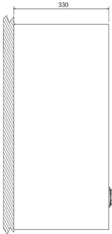
pnc.20-Bmcd6oky
5.2O6mBnN OCHOBHbye3bl
pnc.21-06nBn
5.3 Cxema cncTeMbI OTONNEHn IBC
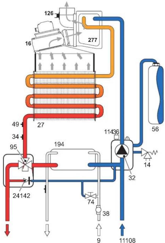
pnc.22-OTONNTBHBKoHTyp
pnc.23-KoHTypTBC
5.4 Ta6nua texHuecknx daHHbIX
BmKHeHHyYbIMKHeHHKOTnA
HaTnCHITb KhoNky on/off (no3.7 - Man.1) Ha 5ceKyHd.
MAN.2-BumKHeHHKOTnA
Habitb y BIMKHeHomy KOTNI eNEKTPnHE XNBHeHna 1e Nodaetcb Ha eNEKTOHNy nATy. Pekkim OanaHHe Ta rapraHO BOPOJocTauHHA BIMKHeHO. Pekkim pO60TN CNTEM npTo3aMeP3Ha 3aJIImaETCB aKTHBOAHM. IIN NOBTOPO BBIMKHeHHO KOTNA 3HOBY HATNCHITb KHONky on/off (No3-7.MaN.1) Ha 5 cekyND.
man.3
Koten 6yde heraiho rotoBn do po60TH KOxHOro pa3y, KOIN BiDyBaCTbC NOXKBaHnRA rapOyo BDO an6o noctyna 3anHT Ha onaneHHN (BID KIMHaTHORo TepMOCTATA A60 dntanchuHoro xPOHOCTa).

PnB BkIIOeHHI eNektpuHOro KINBHeHHra Ta/a60 Ra3y BiD KOtNa CnCTema npOTn 3aMepeAHHe NpauObaTne. RaU Bu He KOpNCTyBaTImTecK OTlOM BnpOBOK TpBaIaONO Yacy BmMky, ToDi, U6b 3anO6irn Horo yUkoJKeHNHO uepe3 3aMepe3aHHe, peKomeHdyEcb 3nNTB CBO Body 3 KOtNa -Rk 3 onAIIOBAhBO HorO KOHTpy Tak i 3 KOHTpy FBn, a60 yBeCTn AHTnFpN3 B onAIIOBaHbHNI KOHTyp BiNDOBiHDo Do BkA3IBOK 3 sez. 3.3.
2.4 PerynkoBHHa
IpeemnKaHnEstate/Inverno (JIto/3Ma)
HaTnCHITb KhoNky Estate/Inverno (JIo/3mua) (INB.6-MaI.1) Ha 2 cekyHd.
Ha nncnne cnanayxc no3ha-ka Estate (Jitro) (DVB. 10 - man. 1): Koten npaoubaHmne Inue Ha Bnpo6hencaHmC HcTeHXHIO BoN. PexHM po6OTn CNTEMn npOTn 3amep3HHA 3annaeTcA kTNBOAHMn
IpyckacybaHHpeKIMyEstate(JIto)3HOByHATNCHTbKHONKYEstate/Inverno(JIro/ 3Ma)6-Ma.1)Ha2cekyHd.
PeryIIOBaHHa TempepatypOnaJIeHHa
HATCHITb KHONKa ONaENHH (no3. 314 Man. 1) DnA 3MiHN TMNEPATpy BID MIHIMAbHOI 30°C do MaKcImMaNbHOI 80°C B Byd-akOMy pa3i He peKoMeHyctbc, 06 KOten npaioob npm Temnepatpy HnKHe 345°C.

man.4
PerynboHHa Tempepatyp B cncTeMi TBn
HaTNCHTb KHONKn CNTeMn TBn (no3.1i2-Man.1),uO6 3mHOBaTN Tempeatpy BID MIMAlbHOI (40°C) do MAkCNMaBHOI (55°C)
man.5
PerynoBaHH KIMHaTHoi TEMnepaTyPi (3a DOnOMoIO KIMHaTHOro TepMoCTata, kNIOCTaAcTbCra 3a OKpEMM 3AmOBHeHHM)
3a DOMONOIO KIMHaTOro TepMOCTATA BCTAHOBITs BaxaHy TEMnepatpy y npMiuieHHI. Y pasi BiCyTOHcToKIMHaTHORo TepMOCTATy TEMnepatypa y kOtJI dyntpymyBaTHCA H a3aDHAMHO 3HAeHHI cyTabKn.
PerynoBaHHaKimHaTHoTeMnepatypn (3a DonomoroH DuctaHuiHoro xpoHOCTata, knn NoctaactbCra 3a OKpeMM 3amOBHeHM)
3a donomoro nctahuiHoro xpoHocata BCTaHOitb 6aKaHy Temnepatpy y npimiuHHI.Tmepatypy npimiuHHI perynkoBaTMeBcno 6kaHHo.3a inopmaueio zo opoBoTH nctaHuiHoro xpoHocaty 3epeHbcno Bo iDnobidro KepinuTBA kopructyaHa.
Bn6ip ECO/COMFORT (EKOHOMI/KOMΦOPT)
Koten mac cneuaibn npncpti, knn 3a6e3neuyc nidaunueHy wbnkictb Bnpo6nehna rapaoycaHTexHIOBOD TaMakmalaHbN KOMpoptd nKOPCTyBaA. Konnpntpi e AKTNBM (pexim KOMΦOPTY - COMFORT), BOda, 0o mictnbc y Kotni, niTprmyEcb npn BiNDobin TMennepatyi, 0o do3OBnRE heraHNO OTPMaTHn rapayBOy HbXOdi 3 KOtla npn BiDkPbNAHHKpahy.
KopnctybaHMOKE BIMKHyTH npncTPIE (eKOHOmiHHNpeKMM ECO), HAHTCHyBHN Ha KONIKY eco/comfort(no3. 7 - Man.1).BpeKMI EKOHOIMIL - ECO Ha mCnnei 3'ABnREbCa CmBON ECO (no3. 12 -Man.1).ДЯ yBIMKHeHnpeKMMy COMFORT (Komfopt) 3HOBy HATNCIb KONIKY eco/comfort (eKOHOImIA/KOMFOpt)(no3. 7 - Man.1).
PerynHOBAHH3 dncTahuiHoro xpoHOCTaTy
Pn nDHaHHi Do KOTna DnCTaHuiHoro XPOHOCTaTy (KmE O onuicO) perynIOBAAH, ONcAHI BUIe, 3JINCHIOHTbCra 3riDNO do Tabinmu 1.
Tabnue.1
| PeryuioBaanHЯ Tempepatур onanenHЯ | PeryuioBaanHЯ MOKHA 3dijChHnT KJ 3 MeHIO DmCTAHnIHOr xPOHOCTATy; TAK I 3 naHEnI KOMANI KOTnIa. |
| PeryuioBaanHЯ Tempepatур rapaoyo cantexhniHoI BODI | PeryuioBaanHЯ MOKHA 3dijChHnT RJK 3 MeHIO DmCTAHnIHOr xPOHOCTATy; TAK I 3 naHEnI KOMANI KOTnIa. |
| NepemKhanHЯ ПITO/3nma (Estate/ Inverno) | PereMnI ITTO (Estate) ε προρίτεTHNIM ΜιδΟ MOKNlBnx zanHtIB ha onanenHЯ 6bOky DmCTAHnIHOr xPOHOCTATy. |
| Bv6ip peKmy ECO/COMFORT (EKOHOMI/KOMΦOPT) | Takmii Bv6ip MOKHa 3pO6HTn I liuee 3 naHEnI KOMANI KOTnIa. |
PerynboHHr iipabniHoro Tcky y KOHTpy onaneHHA
Tnck 3anpabneHH npx xonodHomy KOHTpyi, knn 3'ABNTbCn Ha rIDpOMTe pKOTna (no3. 17 - man. 1), mAc ctaHOBnT 6nn3bKO 1,06ap. KkOTo nck y cNCTeMI ONCTMeI ONCTMbCR HnKHe 3a MInMaJIbHe 3HaHEHH, KOten 3ynHHbCn, a Ha DnCnNeI 3'ABNTbCn KOd HnONaIKn F37. 3a DonomoroIO kpan dJa 3anpabneHH (no3. 1 Man. 6) nobepHtB Tnck Do nochatkoBOro 3HaueHH. HanpiKiUoi onepaui 3abKdn 3akPBAITE KpAH dJa 3anpabneHH.
MaN.6-KpaHdna3a npBaBneHHA
3. MOHTAX
3.1 3arabhi nonoxehn
BCTAHOBNIHOBATI KOTEN IOBNHHI NIIIE ΦAXIBLI BIDIOBHOI KBANIΦIKALI 3 DONTPMAHHREM YCIX BKA3I0K UICEI TEXHICHOI IHCTPYKLIJI, BIMOR IIIOYO 3AKOHODABCTBA, HAUHOHAJIbHX I MICUEBX HOPM, A TAKOX 3A PABINAMI FAPHOI TEXHICHOI IPAKTIKU.
3.2 Micue dnia mohtaxy
KoHTyp 3ropaHn arperaty repmEtHIOIbOBaHH BIDHOcHO npMIMiEHH, De BII BCTAHOBJIeHH, I TOMY KOTen MOKe BIKOPHcTOBByATMC B 6yDb-JAKOMy npMIiueHHI. Ipote pRMIuEHn, B JOKOMY BCTAHOBIOETBCB KOTen, NOBHNE Matn DOCTATHO BEHTNIAIO DnA 3anoBifraHH NHe6e3NeHHN CNTyaui y paai Habitb He3NaHOrO BtOKy RA3y. Lr HopMA 6e3NeKn Bu3haueha DipeKTHBOO CEE No 2009/142 dna BCIX npaioohnx Ha raai arperatib, B TOMY uCNI i dnn TAK 3BaHHx arperatib i3 zakpntoHO kamepoIO.
Koten MOKe npauoBatu yactko BO 3axHHeHOMy MiCui, 3riHDo 3 CTaHApTOM EN 297 np A6, npn MinImaBHiym teMnepatyi -5°C PekomeHdyEYbC BCTAHOBHTN Koten ndi CXINOM daxy, Ha6JIKOHI a60 b3axHHeH Hiui.
YMiCi yCTaHOBkTAKOKe H NoOBHHo 6yTN NnJy, NERKO3aMmCTnx peeH Ta MATEpIaIB a60 arpeCnBHX ra3iB.
Koten npn3haeHm nna HactHHoY cTahOBKn Ta noctaetbca i3 ckoboo dnniDaiuybaHH. 3akpinitb ckoy do CTHH, 3iIDHO BIDMITkAM, Bk3aHMM y Man.17, Ta ndicbcTe KOTen. KpinneHHa CTHI MaC rapaHTyBaTH CTIke I hadiHne YTPMByHHKOTNA.
JIKIO KOTEN BbDyOBYtCBa Y MeBn 6O MOHTyEeBc8 O6OKOM, TpeBa nepeDaunPi npocTIP dNn3HrTn 3axnCHOro KOkyxI HOpMaIbHO RBOKONAHNO pObit 3TexHvHORO 06CnryOByBAHN.
3.3 Fidopotexhiyhi nkioueHH
3ayBaXeHHa
1063anobittnctiKaHHIO BOnHa 3emHIO Bpa3i nepeBunueHHN TCKy y KHTpyi onaneHHN, 3nIB 3anob6kHorO KnanaHy Tpe6a 3'EDnatn 3 NiHOHO A60 Ty6KHO 3bnpabHoI nocdyHH. IHaKHe, KaIO cnpaIOBaHHN 3nHBoro KnanaHy np3BeDe Do 3aJIbAHHH NpIMiEHHN, BIPo6HKn KOtNa He HecTmne BiDNOBIdANBOCTi.
Iepu HbK BnKohyBaTH NIDKNIOHcHH, nepeKaOHteca y BiNobIdHOCTa arperata Ta naPbMa, a TAKO BnKoHaTe peTeJIbe OcUeHHra BCIX TpybOpOBdIB onaHOBaBbHO CIcTcEM.
BnKoHaIe niiKnIOueHn Do BiINOBiDnX WtTyepiB 3riHO MaIOHky Man.19 Ta no3NaKAM Ha cAmOmy KOTNI.
3aybaxenha: onanIOBaIbHn KOHTyp ochaueHn BHytpiHIM nepenyckHM KnanaHOM.
XapakTepeNCTKIN BODN B KOHTpyi onaJIeHHH
Jikuo kopctkictb BODn nepeBnuye 25° Fr (1°F = 10 actn Hn MioH CaCO3), todi, o63 zanobirtn yTBOpEHNO hAKNY y KOtNI, Heo6XiHO BNKOpNCTOByBaTH cneiaIbHO 06pOBEH NOy.
CnCTema npTo 3aMeP3aHH, aHTnFpN3Hi piDHH, npcaKni i cnoBilbHOBaic Kopo3ii
B pasi HeobxHocto Do3BoneHO BkBaTa HnTnFpns3HpiDHN, npnaCdkn i cnobIbNbOaH cy0Kti, are nne 3a MObN aHaanrAraHt3 60ky ix BnPo6KBH b IbadOniHcTb ci piOdyKuJi dne 63neHORo KOpNCTyBAHHa Ta h BiDCYTHcTB pn3Kky yUkoJekh bTn TnenNooMHmHKa Kotna abo IHmX KomNoeHTIB i/a6o MaTePianib KOTn ta BCBo rctATKyBAAH. 3a6oPohrctCBMkOPNCTAHH aHTmDnPH3HX plHH, npcaDok i cnobInbOaHcb KOp03I 3araBHoI dHe npndaTHnx DnBkBAHH y TnenOBNX cIcTeMaX Ta He CymChix 3 MaTePianAmn, BkOPKnCTAHmY kOTni Ta yCTAtKYBAHHi.
3.4 PnKnHoueHHra3y
Piknouenra 3aay Mae 3diChiBaTnca Do BidnoBidiHoro 7TuCyepy (mB. Man. 19) 3 DOpHMAHNM BIMOR YIHHOO 3AOKHOADCBCTBA, MeTaneBOHO JOKCPKTO pTy6KO a60 rHuKM mJahorn 3 cyiJIbHOIO CTIKHOO 3 HeipXaIbOIO chT, BCTaHOBIJIOOH raO8BN bENTINb MIX KOHTypoT aKTOMN. PeKehoAHTeCe y UcJIbHOTCI rAOOBx nID'EDnHb.
3.5 EneKtpnHi niiKnIOueHHa
3ayBaKeHHa
Arperat mac nidcHbTncb do efeKTHBHOI cHTeMn 3a3eMNEHHRA, BIKOHAHOI 3 dOpMaHnM npabun 6e3neKn. EpeKTHBHCtTa BiNobiDHCt CNTeMn 3a3eMnEHnMa nepeBiprTcna NIIue faxibum, BpuoBHK BiXnRae 6yIbKy BiNobiAebHCTBa MoKNBIB 6MTKN BHACNIOK BiCyTHOci CNTeMn 3a3eMnEHnH.
IINI NIKIOENH NOEETPNPOH MEPEXI KOENT OCAUENH KABENEM TNY "Y" 6e3 Wtncen. IINIOHNOEHNHO MEPEXIOBNNH MAtn FIOCBAHE 3EDNAPT BTOONIOCHNNEPENMMKAA 3 BIDCTAHNO MIX KONTAKTM IOHaHMnH 3 MM, POtaaOBOyOuO 3ano6bKNMn HA 3A MIX KOTNM TaJIHcE. BAXHO DToPTMByATNC NOJRAHOCTI (NIHIA: KOPHNBEH NpIT / HEINTPANb CNIH dpIT / 3EMN: KOBTNI-3eEHm dpIT) B nD'EDNAHHx DO eNETPNPOH NIHI.
B KOMNETEHIO KOPNCTYBAaHe BXOINb 3AmHa KaBEnIO XKNBHeHH. Y paai yUkoJXeHHa KaEIO BVMKHiB arperaT,notIM 3BepHITcR NO DOONOMORYdo KbanifikoBaHO raxIBua.DnA 3AMHN BIKOPCTOByTe BKNIOHO Ka6eBb "HAR H05VV-F" 3x0,75 MM2,MakCMmaIbHI diamETp Raoro He nepeBmUyE 8 MM.
KimhaTHm TepMoCTat (onzir)

YBAFA: KIMHATHNI TEPMOCTAT NOBHEH MATI BILbHI KOHTAKTIN. NIKJIOHYOCH 230 B DO KJEM KIMHATHORO TEPMOCTATY, BN BE3NOBOPOTHO 3AIJKODITE EJEKTPOHNY NIATY.
Pn iNkIOeHNI xPOHOCTATIB aOToaMepy He bepiX KMBENHn DnAUX npNCPToB 3IX pO3MKNAOOHy KOHTAKIb. 3a6e3neueHHN ix XMBENHnM NOBHHNO pOBODINrCApeE 6e3nocepeHc NiE'EDHAHn Do MEpexi aO bO 3a DonOMHO 6bATEB, B 3aneKHOCTBI Bt ND TY arperata.
Docyndo Klemho naheni
P3aTbHbHa 3aNcBdPi3nHxPiKIOHe HabeDeHe TAKO Ha eekpHi cxem HA man.24.
man.7-DoctyndoKnemhoi naheji
3.6ДиМоВIТуБОнРБОвДИ
3ayBaKeHHa
ArperatHanexnTbDoTinyC"3repeMTHNOKamepoIO npmmycoBOI TROIO, noaay aOBIPr IBVBEHENBIDPauBObAHIN RAIB MaOTbI ByTH NIDKIOHEI Do OthIE 3 CTCTEM BVBDEHNBCMOKTYBAHHB, BKA3AHN HIXHE. Arperat CTanaptNtBOHOI dno pOBTNI 3dAMAPMR Cy6Byb-koKOHIFpyaui,OnuCAHNH TaBnHUI 3TexIHHMn XapakTePNCTIKAMPi PnUbOMy MOKe 6yTN, UO DeAki KOHIFpyaui 6yDyTB 0MeKehi ABHO, ABO He BiNDoBATM 3akoHAM, HopMAM ABO MicueBM npaBnAM. Ue do yCTAOBKN YCTAKNYBaHHNepeBipte I petenbHO DToTPmYInTe TaNX pO3npAIXKHe. KpIM TORO, DToPTMHyTEB NOPAJTOBAAH TepMIANIH HA CTHI / aO bTeTI i MIHmABHOI BIDCTAHI BID BIKOH, CTII, BEHTINAUINHX OTBOPB, TOIO.
DiaΦparMn
IpaobTn KOTNa Heo6xINO BCTAHOBITniaqpaarmu,IO NOCTaBnHOb3 HmB KOMNKeTI,3rIOH BkA3iBOK,piBBeEHX B TaBnuax HnXy.
Dn iNIOH NpybI nI BnBeENH BIDnpaBohm Rx3iH Heo6xJHO nepeBipTNn PnBnHCTb BNOPKOTBOyBAHOi diaFparmn (pn II BNOPKCTAHNI) Ta II pnnBnHBy yctAHOBY. Y KOTnax cTaNapTHO BCTAHOBHIOYTOCBa diaFparmn HaimEHUOT O diamETpy. 3AmHa biaFparmn (no3.1 - Man-8).Mae npOBoINTnc rIHO do BK3iBOK y man-8.
man.8
PiiknueHHa donomoroo cnibichx tpy6
MaN.9-PnKnai npKnIOeHHa DOIonoMOrIO cnBichnx (koAciabHnx) Tpy6
Tabnua.2-Tunonorria
| Tун | Оtmь |
| C1X | 3abip nobiterpia Bmnyck dmmib rohnohtalbni prnctihnni |
| C3X | 3abip nobiterpia Bmnyck dmmib beptnkailbni daxobni |
Igcnibichoro npneHn H BCTAHOBt Ha arperati OIN 3 TaKnx NoaTKOBNX
enEMeHTB.Po3MpN dNn HACTHHN CBePdNeHb HAdHa H MaHKnHy KaO6KnAHHU. Dnna
3an0birHn MOKNIBORO 3BOPoTHORO CTiKaHN KOHeHCAty 30Hi Ta KpanaHH
Hne6O1DHO, 006 MoKNBI Ropn3OTAnbHI cactHN Tpy6OpOBoIDB nB iBdeEHH
BiDnpaobAHx ra3IB BCTaHOBNIOBAHNc 3 JERKIM HAXNIOM B6ik Kotna
041002X0
041006X0
041001X0
MAN.10-NoaytkoBi enemEnn KoakciabHx Tpy6onpoBod
Ta6nua.3-Diaqparm dnn cnibichnx Tpy6onpoBodIB
| CnibicnH 60/100 | CnibicnH 80/125 | |||
| МakcimbaHa Do3Bolna DoBxHnHa | 6 M | 12 M | ||
| KoebicnHCT 3MENIIeHnKa KOnHO 90° | 1 M | 0,5 M | ||
| KoebicnHCT 3MENIIeHnKa KOnHO 45° | 0,5 M | 0,25 M | ||
| ДiaΦparma,Яу НбIxIDNo ВИКОПСТОВУВАЛ | 0ч2M | Ø45 | 0ч6M | Ø45 |
| 2ч4M | Ø50 | 6ч12M | Hemac DiapparMM | |
| 4ч6M | Hemac DiapparMM | |||
PiiknoueHHa DOnOMoHO BIDOKpEmHeHx Tpy6
Ta6nua.4-Tunonorir
PerynboHH noTyKHOCTi po3nAnIOBHH
Дя ретуюваньnotyxhocti po3anenHH nepebeidt b keten y pekIM TcTeYBaHn (TEST) (DNB,sez.4.1) Hatncitb KHONK cNCTeMn TBN (DNB 1 - Man. 1), u6b3InbWHTn a60 3meuHHTN notyxhictb (MIHImaIbHa=00, MaKcImaIbHa=60). HATNCITb KhoNky CKnDaHH reset, npotrrom 5 cekyHd 3a6e3neUcTbCp6oTa Ha MaKcImaIbHi nnotyxhocti, rka 6yna tInbKn 7a3aHa. BmDItb 3 peKIMy TcTeYBaHn TEST (DNB.
sez.4.1)
4.2 Nyck B ekcnnyatauio
NepuHix yBIMKHyTN KOTen
YneBHItbc y uinbHocti ra3OBOro KoHTpy.
- IpepeBipTe nizip y po3wnpOBAbHOMy 6aKy.
3anobHtB ripabnHm KOHTyp, 3a6e3neuBn noBn Bnycn nobITpr 3 KOTna Ta 3 KOHTpy.
Pepbeipte, 6o6 He 6yno BtOkB 0Dn B KOHTypi OAnEHn, y KOHTypax ΓBΠ, Ha EJDAHNHx A6O y KOTNI.
Ipebeipte npabunbHctb niknuehenra ekeKtpoctaTKybaHHa Ta pO6Oy cIcTeM33aMeHHA
- PeneBPe, 306 3NaueHHH TnCKy r3y DnIa CnCTeMM ONaJIeHHNb 5yIO TaKIM, AOK nToPi6He.
IpeepieTe,io6y6e3nocepeneHn 6n3bKocTi BiD KOTJa He 6yNo JERKOaMMCTNX piHN a6o MaTePianB
Ipebeipkn niicac po6oTn
YbimKHiB arperat.
- YneBHItbcy y uinbHocI KOHTpy roPiHH I BOaHnx CnCTem.
IpeBipRte efeKTHBHCb DnMOxOy i nobITpRAHO-IMMOBnx Tpy6oPBOBqIB niD uac po60TN KOTna.
PpokOHpnHnTe npabInbHicThc uKpkyraBIO nMIX KOTnOM iCmTeMaMn.
YneBHITbca y ToM, 10 ra3OBn Klanah npabInbNo npaioc k y pa3i onaneHHa, Taki y pa3i npiroTyBaHHra paoi caHTexHiHO BOn.
Ipebeipte,yno6peKOTen pO3nAIOeTcB,CBNKOBaUN DEkINbKa npO6Hx pO3nAIOBaHb i BmIKaHb 3a donOMOrIO KIMHaTHORo TepMOCTa a60 dmCTAHUHOrO KEpyBAHH.
- Ipebeipte Bnpatra Tn anna 3a nHbHKOM Ta npOBHHaTe IX 3HaueHHaM y TabmIe texHHxDahnx cap.5.
- PepeKoHaTeC, 00 63 3aNHTy Ha onaNeHHn NaIbHnK KopeKTHo PO3NaIIOEbCS npi BIDkPITTI KpAhy 3 rapAHO BOHO. PepeKoHaTeC, 00 nD vac po6Otn Ha onaHeHn, npn BIDkPITTI KpAhy 3 rapAHO BOHO, 3ynHnEbCS uPKyLJIuHn HACOC ONaHEHn TBAKOHyEcB pIrrTOYBaHHn CAHTExHvHoi BOiN.
Ipepeipre npabnblhictb nporpamyBaHHnapametpiB i BmKoHaHTe Heo6xdHe HanaTuBaHH (KOMNEHcauiHoi KPNBOi, NOyXHOCT, TEmNepaTyPi, ToO).
4.3 TexHiYe o6cIyroByBaHHa
PepiouHn KOHTpObl
Ioo3a6e3neuHTn HanexHy nOBoTpBany po60Ty KOTna, pa3 Ha pik faxibui Maotb BIKOHyBaTu Taki nepeBipKn:
- Pnucpoi ynpabinHHI 63neKn (ra3OBn Knaan, Bntpatomip, TepmoctatN, Too) nobHHH cyHKJIOHyBAtn npabnIbHO.
KoHTyp BnBeHnB BiDnpaBObaHnx ra3iB NOBHe MAtN 6e3OraHHy eFKeTHBtCTb. (KoTeI 3 aKpTIO Kamepo: BeHTnIaTOp, pene Tcky nobITpy, Toio - 3akpTa kamepa Ma6 6TuR repMeTHHOIO: yuINbHeHHa, 3aTNckAci dny Ka6eJIb, ToIO). (KoTeI 3 BiDkPtoIO Kamepo: nepeBau Tary, TePMocTd HMOBIX ra3iB, ToIO). - Nobitprno-HdNMOBI TpybOpnoBODNI orOLOBKN (06MxgyBaU) He nobHnHi MaTHnepeuKoI bUTOKIB.
PnabHnK iTeIIOo6MHHK MaOTb 6yTN UcTMMi 6e3 HauNpy a60 Harapy. DnOuHHeHHa p3i Heo6xjDHOCTI He BnKOpNCTOByte XIMNKATn a60 cTaneBtiKN.
EneKtpoMa6 6ytN 6e3 Harapy i npabunbHO BCTaHOBNEHM.
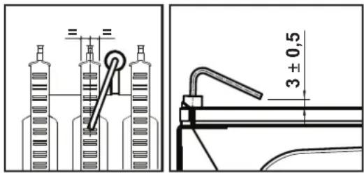
MAN.16-Po3TaWyBaHHeNeKtpOdy
- Ra3OBI I BO4Hl CNTEMM MAOTb 6yTN UINbHMN.
TCK BOyu xOIOHm CNTeMI Mae CTAOBHTn np6n3HO 1 6ap; kUo ce He TaK, NOBepHtIb NOrO Do LbOro 3HaueHH.
LupkyraHnHaocHe noBHe 6yT3a6nKOBaHm.
P03wnpIOBaJIbHm6aKMa66yTn3anpaBneHM
Bntpatn Tnck ra3y nobHHI BiDnOBiTaN Bka3aHmY BiDnOBiHnx Tabnucx.
4.4 YcvHeHH HeCnPaBHOcte
Iiarhoctnka
Koten 6nabHaHO CuyachOIO CNCTeMO ABOTIOHOCTKN. Y pasi npoyueHHA B po60I KOTI DaCnJIe 6nnMaTHME pa3OM 3 no3NaUKO HEnoNAkNI (no3. 11 - Man.1), Bk3aQyHcH Na KOd HEnoJAkNI.
MaioTbca Taki HecnpabHocti, kki cnpuHHIOB noCTIhe 6nOkyBaHH (no3Haehi nitepoo "A"); IaII BINOHNHbPOBOT NOCTAHBO HATINCHHTN KHONKY RESET (no3.6- man. 1) ha 1 cekyHy dbo KNONKY RESET dmctanHoro xpoHOCTaty (kHK e onuicO) b paai BIKOPNCtAHNOCTAHBO; kto He po3noHnae p06Oby, tpe6a ycHyTu nlo Henonadky.
HuiH HENONADKNIOK3HAHAIOTBCNITEPOHOF")CNPWHNHOITbTMMACOB 3aIbOyBANBA,RAE3HIMAcTBcABOMATMIOHO TINbKN-H03HaHEHHRAPamepTy NOBEPTaehCBY MEXI HOPMANBHOI PO60THKOTNA.
Ta6Jnue HenoJaok
Ta6nua.8-Pepeiik Henonao
| KoД ненолади | Helenadka | Можлова р孥чпа | Сnocи усанни Спосию Спосию Спосию Спосию Спосию Спосию Спосию Спосию Спосию Спосию Спосию Спосию Спосию Спосию Спосию Спосию Спосию Спс Термоста |
| A01 | Палынк He розалюстя | Вidсушисть raу | Палыргт, ч i різношірні notik rasy do kotma i ч Budanene nošiigra 3 trpobpoвдя |
| Порушени y ровот evelkropondа posnvalobань/nspocrepeхени 3a ногу'mя | Палыргп ničdikungени evelkropondу ta myo pravil'the posstauybahand, a takiok Bidcuyhichb Harapy | ||
| Небравли raizов knanaн | Палыргп i zamniht b raizovb knanaн | ||
| ПOTужнICTb posnvalobань дуку нizьka | Вidретулійе notykhic'tb posnvalobань | ||
| ВИсокий рі�енb Коц'deнсату | Зільній / опіс'tьch с��фон | ||
| A02 | Спнел наимьстіnomу' рpr вимьнбуну малынky | Порушени y ровот evelkropondа | Палыргп evelkropondobuxу нійсівального evelkroponda |
| Helenadka пnatу | Палыргп пnatу | ||
| A03 | Спрашовүүхүлүхүлүхүлүхүлүхүлүхүлүхүлүхүлүхүлүхүлүхүлүхүлүхүлүхүлүхүлүхүлүхүлүхүлүхүлүхүлүхүлүхүлүхүлүхүлүхүлүхүlэ прета нерерриу | Ушдөн徳н дatчн temperaturiy bo'du B Оралкәвальнomy KOntурi | Палыргп ррашьні posstauybahand i Фунksiohyabuanny daturika temperaturiy bo'du Оралкәвальноi сухтymi |
| Вidсушисть урхлүлү Бдд BOралкәвальн СистEMS | Палыргп урхлүлү насо насо насо | ||
| ПисчнICTb nobitray BOралкәвальн сухтymi | ВIMуystь nobitray 3 Оралкәвального кочтур | ||
| Спрашовүүхүлүхүлүхүлүхүлүхүлүхүлүхүлүхүлүхүлүхүлүхүлүхүлүхүлүхүлүхүлүхүлүхүлүхүлүхүлүхүлүхүлүхүлүхүлэ ТермостаT | Палыргп, ч ррашь ррашь. Злароб Злароб Злароб Злароб Злароб Злароб Злароб Злароб Злароб Злароб Злароб Злароб Злароб Злароб Злароб Злароб Злароб Злароб Злароб Злароб Злароб |
| KoI Helenonadkin | Helenonadka | Можлеса п Primma | Спосiod усанун |
| F04 | 36iB v napametpax pntatn | Помпхова установа napametry pntatn | Перевгсia за необ��иоста зимить napametri pntatn |
| F05 | Рente Trcky nobitpr (небядддддддддддддддддддддддддддддддддддддддддддддддддддддддддддддддддддддддддддддддддддддддддддддддддддд Ткпбткчпргм 20 сухи д icпя aktniblaauii BeHTINATOPA) | Ко��лес рente Trcky / повлгета bIDКИТN | Перевгсia рente Trckx / Венилготр / Розелу berinlrgotopa |
| Нсрпавна eNEKрponpoBDa kpe Trcky nobitpr | Перевгсia похлгосту dikaparIM | ||
| Нсрпавна diapparma | Перевгсia вдногинь diapparIM | ||
| Димар мбЕнрвltы pozimor abo zacmichen | Перевгсia doвкину Димови kanan / Oчирпь ddimobii kanan | ||
| Pente Trcky nobitpr (небяддддддддддддддддддддддддддддддддддддддд Ткпбткчпргм 3a 20 cek робу ти BeHTINATOPA) y 3b'яу 3i српсшьаннг mertmoctatу димови ratie | Збордддддддддддддддддддддд Ткпбткчпргм 3a 20 cek робу ти BeHTINATOPA) y 3b'яу 3i српсшьаннг mertmoctatу димови ratie | Очирпь Trнлобшніни | |
| Зборддддддддддддддддд Ткпбткчпргм 3a 20 cek робу ти BeHTINATOPA) y 3b'яу 3i српсшьаннг mertmoctatу ratie | Перевгсia рente Trckx / Венилготр / Розелу berinlrgotopa | ||
| A06 | ВidсунICTь ngу'mя nicraу yBIMKHeHNN | нсьькч trckx w coNTур i rasу | Перевгсia trckx rasy |
| Калбрваань mIHmAlhNoTo TmCKy nanbHnka | Перевгсia захень Trckx | ||
| F07 | Pente Trcky nobitpr (контакт Замени ni lid acа aktnBaцii BeHTINATOPA) | Ко��лес рente Trckx/ повлгета bIDКИТN | Перевгсia рente Trckx / Венилготр / Розелу berinlrgotopa |
| Нсрпавна eNEKрponpoBDa kpe Trcky nobitpr | Перевгсia похлгostу dikaparIM | ||
| Нсрпавна diapparma | Перевгсia doвкину Димови kanan / Oчирпь ddimobii kanan | ||
| Димар мбЕнрвltы pozimor abo zacmichen | Перевгсia doвкину Димови kanan | ||
| A09 | Порушену y probotiy raizoboro kstanayu | Рozrim b eNEKрponpoBovdax | Перевгсia похлгostу dikaparIM |
| Нсрпавна raizoboro knana | Перевгсia захинь dikaparIM | ||
| F10 | Helenonadka Hanipiroho datvyika | Yuzodokhenny datvyk | Перевгсia похлгostу dikaparIM |
| Замени b eNEKрponpoBDa | Перевгсia похлгostу dikaparIM | ||
| Рozrim b eNEKрponpoBDa | Перевгсia похлгostу dikaparIM | ||
| F11 | Helenonadka datvyka tempepatyrm boD B KOHTpyi ΓΒΙ | Yuzodokhenny datvyk | Перевгсia похлгostу dikaparIM |
| Замени b eNEKрponpoBDa | Перевгсia похлгostу dikaparIM | ||
| Рozrim b eNEKрponpoBDa | Перевгсia похлгostу dibarIM | ||
| A15 | Pente Trcky nobitpr (небяддддддддддд Ткпбткчпргм 20 сухи д icпя aktniblaaasi BeHTINATOPA) | Зногадka F05 Зногаюнь 5 pasiv b ocstahni 24 rozhdin | Див. helonaу F05 |
| A16 | Порушену y probotiy raizoboro knanayu | Рozrim b eNEKрponpoBovdax | Перевгсia похлгostу dikaparIM |
| Нсрпавна raizoboro knana | Перевгсia захинь dikaparIM | ||
| A23 | 36iB v napametpax pntatn | ПOMMIXOBA UCTANOBa napametry pntatn | Перевгсia захинь dikaparIM |
| A24 | 36iB v napametpax pntatn | ПOMMIXOBA UCTANOBa napametry pntatn | Перевгсia захинь dikaparIM |
| F34 | HampuraЖишения Нigнke 3a 140 B 3M.ctrp. | Поблелем b eNEKрponpvchni Мерекi | Перевгсia похлгostу dikaparIM |
| F35 | Helenopmalny hauctota strcmy b eNEKрннii Мерекi | Поблелем b eNEKрponpvchni Мерекi | Перевгсia похлгostу dikaparIM |
| F37 | Helenonilblnni TnCx BoD n KOnturti onanenHn | Тпс Занаду Тньын | Заловпь снctemу Вбоку |
| Рпс ТSCKу BoD n piD'dEAnne b abo yuzokdavn | Перевгсia datvyk | ||
| F43 | Cnpaalbovye 3azixt Trnkno mbHnNka. | ВidcyTNICbUcPkiYnBzU H₂O B KOHontiy olanenHn | Перевгсia похлгostу насOC |
| ПрсунICTь nobitpr b OANIOBANHOMy KOHontiy | ВИиуctь nobITray 3 OANIOBANHOrO KOHontiy | ||
| F50 | Helenonadka v po6oTI 6bOKy uynpaBInHHDBM32 | ВУнг�ПИЯ NOVIKIIББКБФ Унг�пИЯ NOVIKIIББКБФ | Перевгсia зазemлесу Ту рао zeHTPablny 6bOKx kepybaHn. |
| F51 | Helenonadka v po6oTI 6bOKy uynpaBInHHDBM32 | ВУнг�ПИЯ NOVIKIIББКБФ Унг�пИЯ NOVIKIIББКБФ | Перевгсia зазemлесу Ту рао zeHTPablny 6bOKx kepybaHn |
5.XAPAKTEPNCTIKNTA TEXHIHIDAHI
Ta6nua.9-ymoBbHn03HaueHHMa1.19,Man.21,Man.22i Man.23
5 3akmTa kamepa
7 PnBepenHra 3y 0 1/2"
8 Buxid BoDn CnCTeMn TBn 1/2"
9 BxID BOIN CHCTEMI TBN 01/2"
10 Ppma Jnir (npa) B KHTyp OanenHH 3/4
11 3BopOnHa HnH KOnTpHy onaHnH 3/4
14 3an06ixn knanan
16 BeHTnTATop
19 Kamepa 3ropHHH
22 PJIbHKK
27 Tnno6minHm3 mdi dnn onaneHHH rapaHOr BOPOOCTAHHH
28 Konektop biipaaobabmXra3iB
29 Konektop dna BIDBedeHHa BIDnpaBbAHx ra3iB
32 LpkynuaHmHaocKoHTpy oanaeHH
34DatTmTemnepatymonaneHH
36 ABtOMaTHHmKnBnBnDnBnTyCxy NOBITpR
37ΦnbtpBxOyXoJHOIBOH
38 Bntparomip
39 06mexybaB mtpaB
42 DaTHMK TEmpepatyn B CnCTemI TBPI
43 Pene nacky noobtpn
44Ta30eMknanaH
49 3anob6eHH TepMOCTAT
56 P03mPbOaBbHbBbBb
74KpaHpIra3aONBHeHHBODIO CnCTEMO
81 EneKtpoa poznaIIOBAAHn cnoctapekeHHHa 3a noTymS
95 BiDbiHm knanan
114 Pene Tmcky 800n
187 Diaφρarma nπa Biaŋpaúbaobαhnx ra3iB
194 Tennoo6mHHK KOHTpy TBn
241 AToMAtMNnHnepeNcyHNKnlaHn (6BaNaNC)
364 FTH npT yTbOpHH KOHcHcTy
5.1 Ra6apntHi po3MiPi i nikNooyenHa
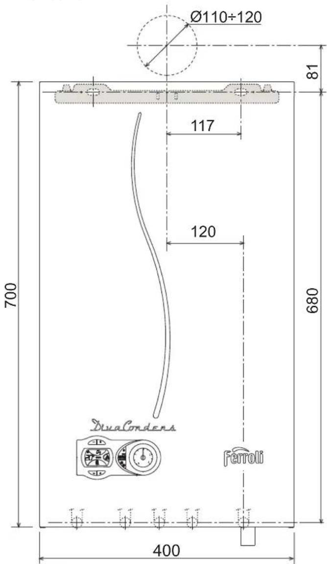
man.17-BurnaCnepey
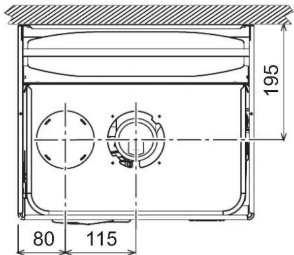
man.18-Burnnn3Bepxy
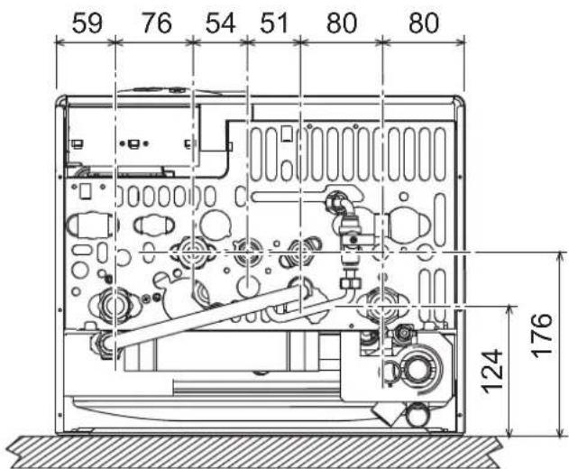
MAN.19-Bnrrna3Hn3y
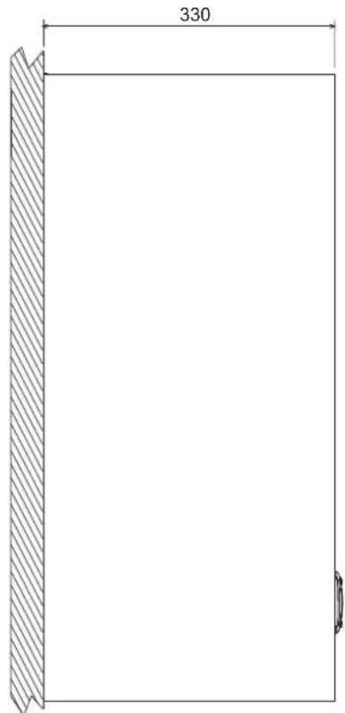
man.20-Burna36oky
5.23arabHmBurnndIOchOBHiBy3nn
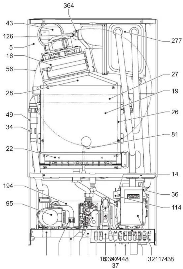
man.21-3araanbHmBnra
5.3 FidpaBniHm KOHTp
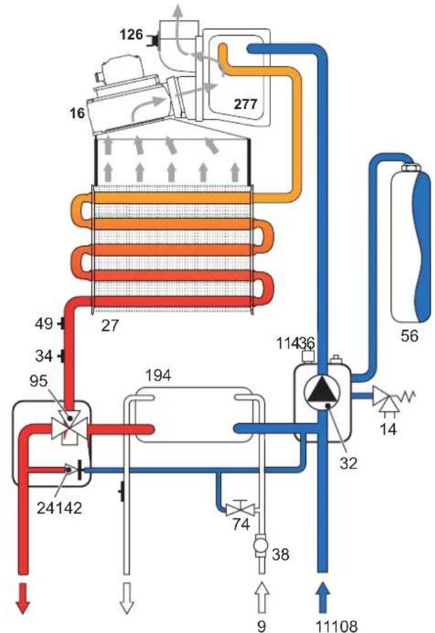
MaI.22-OnaIIHOBaJIbHn KOnTyp
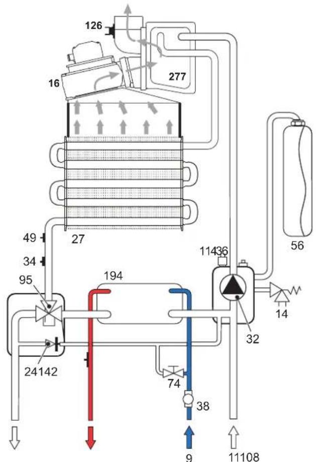
Ma1.23-KoHTypΓBn
5.4 Ta6nnua TeXhivnX naHnx
| Однения дампx | DIVAcondens F24 | DIVAcondens F28 | ||
| Мakсмалынотеллорodукхшпсь сimestем ораленян | KBr | 25.0 | 28.0 | (Q) |
| Мaksmалынтеллорodукхшпсь сimestем ораленян | KBr | 10.0 | 10.0 | (Q) |
| Мaksmалынтеллоровnotукхшпсь сimestем ораленян (80/60°C) | KBr | 24.1 | 27 | (P) |
| Мaksmалынтеллоровnotукхшпсь сimestем oраленян (80/60°C) | KBr | 9.2 | 9.2 | (P) |
| Мaksmалынтеллоровnotукхшпсь сimestем oраленян (50/30°C) | KBr | 25.9 | 29 | |
| Мaksmалынтеллоровnotукхшпсь сimestем oраленян (50/30°C) | KBr | 9.6 | 9.6 | |
| Кошчicentн корочи di P'max (80-60°C) | % | 96.5 | 96.5 | |
| Кошчicentн Корочи di P'min (80-60°C) | % | 92.0 | 92.0 | |
| Кошчicentн Корочи di P'max (50-30°C) | % | 103.5 | 103.5 | |
| Кошчicentн Корочи di P'min (50-30°C) | % | 96.0 | 96.0 | |
| КДI 30% | % | 100.2 | 100.2 | |
| Орсун� палынka G20 | wt.xO | 11 x 1.35 | 11 x 1.35 | |
| Тимк подд рasy G20 | Mбap | 20 | 20 | |
| Мakc. Тимк на палынг G20 | Mбap | 11 | 14 | |
| Мн. Тимк на палынг G20 | Mбap | 2 | 2 | |
| Мakc. вит ratу rasy G20 | M'roq | 2.64 2.96 | ||
| Мн. вит ratу rasy G20 | M'roq | 1.06 1.06 | ||
| Орсунун палынka G31 | wt.xO | 11 x 0.82 | 11 x 0.82 | |
| Тимк подд рasy G31 | Mбap | 37 | 37 | |
| Мakc. Тимк на палынг G31 | Mбap | 29 | 35 | |
| Мн. Тимк на палынг G31 | Mбap | 5 | 5 | |
| Мakc. вит ratу rasy G31 | Kroq | 1.96 | 2.19 | |
| Мн. вит ratу rasy G31 | Kroq | 0.78 | 0.78 | |
| Клас epфокиноста зди д配电�вюо 92/42 EEC | - | ★★★★★ | ||
| Клас вдд NOx | - | 3 | 3 | (NOx) |
| Мakсмалын рobocун тхсь в сimestем ораленян | bap | 3 | 3 | (PMS) |
| Мaksmалын рobocун тхсь в сimestем ораленян | bap | 0.8 | 0.8 | |
| Мaksmалын тиморурачу в сimestем oраленян | °C | 90 | 90 | (lmax) |
| Бмст Bodу рда ораленян | n'tpH | 1.5 | 1.5 | |
| Смн ctrь розшmicьанho baskу д借贷 сimestем ораленян | n'tpH | 8 | 8 | |
| Тимк вдд у розшmicьалыну baskу д借贷 kontуру ораленян | bap | 1 | 1 | |
| Мakсмалын рobocун тхсь сimestем TBI | bap | 9 | 9 | (PMW) |
| Мaksmалын рobocун тхсь сimestем TBI | bap | 0.25 | 0.25 | |
| Вит ratу rapayо cal'texchnyн оdni рmp DT 25°C | n'txB | 14 15.7 | ||
| Вит ratу rapayо cal'texchnyн оdni рmp DT 30°C | n'txB | 11.6 | 13.0 | |
| Клас zamchictry | IP | XSD | XSD | |
| Нарухшлиу | BtU | 230B/50Tu | 230B/50Tu | |
| Стохмалая онлайн ратниотунсь | Bt | 95 | 110 | |
| Bara (popovich) | Kt | 35 | 35 | |
| Тлару atу | C12-C22C32C12-C2-C2-C2-C2-C2-C2-B2-B2-B2 | |||
| PIN CE | 0461CP1030 | |||
5.5 Cxemu
Cxemn Tncky - notyXhoctl
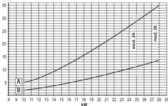
mbar
A=GPL-B=METAH
YtpaHAnOpy uKpyiHnx Hacocib
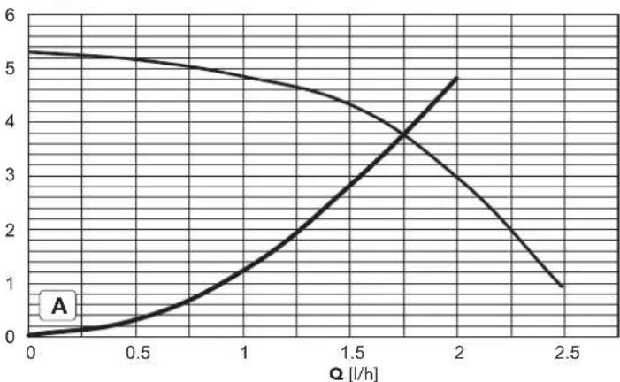
H [m H2O]
A = YtpaTHANOPYyKOTNI
5.6 EneKtpnHa cXema
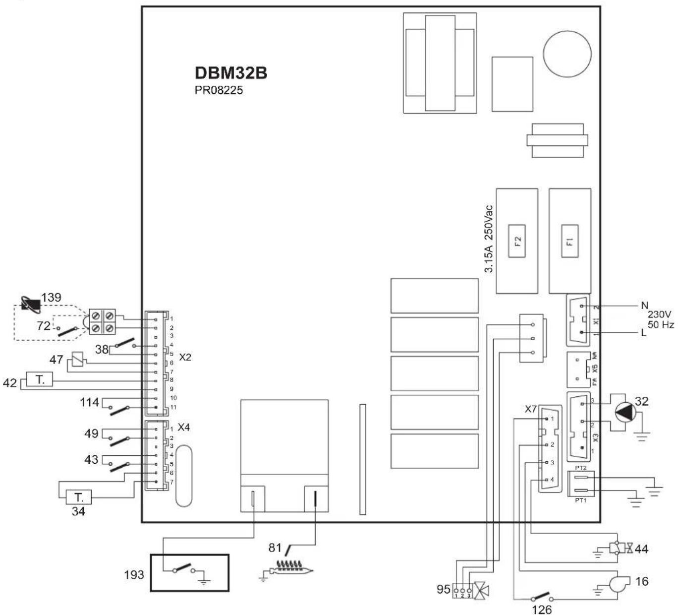
man.24 -EneKtpnHa cxema

Ybara: Iepn Hix nIeHaTH KIMHATHN TepMOCTa 60 DCtAHuH NxPOHOCTa, BmMItb nepeMHUY 3 KNEMHNA.
16 BeHTnIaTOp
32 LnpkynuiHHn HAcOC KOHTpy onaJIeHHA
34 TaTHK TEMNepaTpyn BODn OAnHOBaJIbHOI CNTeM
38 BuTpaTOMip
42 DaTnK TemnepaTyB CnCTeMIΓBn
43 Pene tcky nobitpr
44Ta3OBnKlnanH
47 MoynkoBbHa KoTyka Modureg
49 3anobixHH Tepmocta
72 KimHaTHn TepMOCTaT (noCTaayEbCg OKpeMo)
81 EneKtpoD po3nAHOBAAHr/CnoCTepeXeHHr 3a noNym'
95 BiDbiHni KnaHa
114 Pene Tucky BoDn
126 KOHTaKTHm TepMOCTaDMOBxra3IB
139 DnCTaHuiHmXPOHOCTa(kaynbTaTNBHO)
193 CnΦoH
EN Declaration of conformity
Manufacturer:FERROLI S.p.A.
Address: Via Ritonda 78/a 37047 San Bonifacio VR Italy
declares that this unit complies with the following EU directives:
Gas Appliance Directive 2009/142
ErP Directive 2009/125
Low Voltage Directive 2006/95
Electromagnetic Compatibility Directive 2004/108
C
President
Paola Ferroli

FR


- OPERATING INSTRUCTIONS
- Introduction
- Control panel
- Panel key fig. 1
- Indication during operation
- Heating
- Domestic hot water (DHW)
- Comfort
- Fault
- Lighting and shutdown
- Connection to the power supply
- Switching the boller off and on
- Adjustments
- Summer/Winter Swithover
- Heating temperature adjustment
- DHW temperature adjustment
- Room temperature adjustment (with optional room thermostat)
- Room temperature adjustment (with optional remote timer control)
- ECO/COMFORT selection
- Adjustments from Remote Timer Control
- System water pressure adjustment
- INSTALLATION
- General Instructions
- Place of installation
- Plumbing connections
- Important
- Water system characteristics
- Antifreeze system, antifreeze fluids, additives and inhibitors
- Gas connection
- Electrical connections
- Room thermostat (optional)
- Accessing the electrical terminal block
- Fume ducts
- Baffles
- Connection with separate pipes
- SERVICE AND MAINTENANCE
- Adjustments
- Gas conversion
- TEST mode activation
- Adjustment of pressure at the burner
- Heating power adjustment
- Lighting power adjustment
- Startup
- Before lighting the boiler
- Checks during operation
- Maintenance
- Periodical Inspection
- Troubleshooting
- Diagnostics
- Table of faults
- TECHNICAL DATA AND CHARACTERISTICS
- FR
- DISPOSITIONS GÉNÉRALES
- Selection Eco/Comfort
- Raccordement gaz
- BkIIOyehne N BblKIOyehne
- IopKIOUeyHe K cETn 3NEKtpONtAHm
- Bknoyehne n Bbiknoeyehne kOtna
- Perynnipobknu
- IpeeknoueHne pexmOB "JTeTo"/"3nMa"
- Perynnpobka TempepatbI BObl B CnCTeMe OToJIeHn
- Bb6oppeKmOBECO/COMFORT
- PerynpoBaHne c dNCTaHcUHOHHoro nyIbTa ynpaBHeHra c TaMepom
- Perynpobka daBneHnBaOdbicnteMe
- MOHTAX
- yka3aHn8 o6uero xapaKTepa
- Mecto yctahOBKu
- Hnpabnueckne coeHHeHna
- PpeDynpexkdeHn
- XapakTeepnKu BOBdIIN CNTeMbOTONneHn
- CnCTema 3aunbIOT 3amep3aHn,KnKne aHTnΦp3bl,do6aBkn n HnRn6ntOpbl
- Ra3OBbIe coeHHeHn
- ΘeKtpnueckne coeHHHeHna
- PpeynpeKdHn
- TePMoCTaKOMHaTHOH TemnepaTpybI (onu)
- OcTyK 3NeKtpnuecko KJEMMHO naHenn
- 3.6bIMOXOaI
- PpeynpeKdenn
- DnaΦparMbI
- Ta6nua.2-BapnaHTbI nCnonHeHHa
- YXOD IN TEXHmECKOE OBCJNYKUBAHME
- PerynipobKu
- IpehaetpokaHa npyroTnra3a
- AKTINBaUNrTeTOBOro peKmAs TEST
- Perynpobka daBleHna ropeIky
- PerynpoBka MouchoNt OToJIeHn
- PerynpobkAMoHocnpo3knra
- BbOaB 3KcNpyTaumHO
- IpepeBknHcHEmKOTna
- KoHTpOlbHbIe Opeaun, BbINOJIHReMbIe BO BpEmpa60TbI
- TexHnueckoe 65nyKuBaHne
- Pepnoaueckn KOHTpOJIb
- YctpaHeHHe HncpbaBHOtei
- DnarHocTNka
- Ta6nua HncnpaBHOCTe
- BmKHeHHyYbIMKHeHHKOTnA
- PerynkoBHHa
- IpeemnKaHnEstate/Inverno (JIto/3Ma)
- PeryIIOBaHHa TempepatypOnaJIeHHa
- PerynboHHa Tempepatyp B cncTeMi TBn
- PerynoBaHH KIMHaTHoi TEMnepaTyPi (3a DOnOMoIO KIMHaTHOro TepMoCTata, kNIOCTaAcTbCra 3a OKpEMM 3AmOBHeHHM)
- PerynoBaHHaKimHaTHoTeMnepatypn (3a DonomoroH DuctaHuiHoro xpoHOCTata, knn NoctaactbCra 3a OKpeMM 3amOBHeHM)
- Bn6ip ECO/COMFORT (EKOHOMI/KOMΦOPT)
- PerynHOBAHH3 dncTahuiHoro xpoHOCTaTy
- PerynboHHr iipabniHoro Tcky y KOHTpy onaneHHA
- 3arabhi nonoxehn
- Micue dnia mohtaxy
- Fidopotexhiyhi nkioueHH
- 3ayBaXeHHa
- XapakTepeNCTKIN BODN B KOHTpyi onaJIeHHH
- CnCTema npTo 3aMeP3aHH, aHTnFpN3Hi piDHH, npcaKni i cnoBilbHOBaic Kopo3ii
- PnKnHoueHHra3y
- EneKtpnHi niiKnIOueHHa
- 3ayBaKeHHa
- KimhaTHm TepMoCTat (onzir)
- Docyndo Klemho naheni
- 3.6ДиМоВIТуБОнРБОвДИ
- DiaΦparMn
- PerynboHH noTyKHOCTi po3nAnIOBHH
- Nyck B ekcnnyatauio
- NepuHix yBIMKHyTN KOTen
- Ipebeipkn niicac po6oTn
- TexHiYe o6cIyroByBaHHa
- PepiouHn KOHTpObl
- YcvHeHH HeCnPaBHOcte
- Iiarhoctnka
- Ta6Jnue HenoJaok
- 5.XAPAKTEPNCTIKNTA TEXHIHIDAHI
- Ra6apntHi po3MiPi i nikNooyenHa
- EN Declaration of conformity
Brand : FERROLI
Model : DIVAcondens F28
Category : Boiler