RoomMatch - Speakers BOSE - Free user manual and instructions
Find the device manual for free RoomMatch BOSE in PDF.

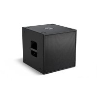
| Product Type | Subwoofer for suspended installation |
| Brand | Bose |
| Model | RoomMatch (e.g., RMS215) |
| Category | Professional speakers |
| Estimated dimensions (W x H x D) | 1092 x 610 x 660 mm |
| Estimated weight | 77 kg |
| Cabinet material | Plywood |
| Power handling | Passive (requires external amplifier) |
| Installation type | Suspended, reserved for professional installer |
| Suspension points | Minimum 4 points per enclosure |
| Insert thread type | M10 (metric) – do not use SAE 3/8" |
| Fastener grade | Metric 10.9 or equivalent |
| Minimum number of engaged threads | 14 threads |
| Recommended torque | 47 - 54 Nm |
| Maximum total suspended load (RMS215) | 231 kg |
| Safety cable recommended | Yes, attached separately from the mounting system |
| Maintenance and cleaning | Periodic inspection of fasteners and structure |
| Recommended use | Fixed professional sound systems |
| Warranty | Standard manufacturer warranty (consult Bose) |
| Included accessories | Not specified (refer to installation manual) |
Frequently Asked Questions - RoomMatch BOSE
User questions about RoomMatch BOSE
0 question about this device. Answer the ones you know or ask your own.
Ask a new question about this device
Download the instructions for your Speakers in PDF format for free! Find your manual RoomMatch - BOSE and take your electronic device back in hand. On this page are published all the documents necessary for the use of your device. RoomMatch by BOSE.
USER MANUAL RoomMatch BOSE
Installation and Safety Guidelines
This product is intended for installation by professional installers only! Thank you for selecting Bose® RoomMatch™ subwoofer for your sound reinforcement system. This document is intended to provide professional installers with basic installation and safety guidelines for Bose RoomMatch™ subwoofer in typical fixed-installation systems. Please read this document before attempting installation.

WARNING: All Bose® products must be used in accordance with local, state, federal and industry regulations. It is the installer's responsibility to ensure installation of the loudspeakers and mounting system is performed in accordance with all applicable codes, including local building codes and regulations. Consult the local authority having jurisdiction before installing this product.

WARNING: Unsafe mounting or overhead suspension of any heavy load can result in serious injury and equipment damage. It is the responsibility of the installer to evaluate the reliability of any mounting method used for their application. Only professional installers with the knowledge of proper hardware and safe mounting techniques should attempt to install any loudspeaker overhead.
Guidelines for Permanent Installation of RoomMatch™ Subwoofer
The installation information contained in this document is only a general guideline and cannot, as such, represent all requirements and precautions. Accordingly, anyone using this material assumes all liability and is expressly responsible for the safety of all loudspeaker array designs and mounting configurations applied in practice.
1) Prior to the installation of any overhead loudspeaker, a licensed professional engineer must approve the location and method of attachment to the building structure and confirm they are consistent with all building codes and regulations. Ensure the mounting surface and the method of attaching the loudspeaker system to the surface is capable of supporting the total weight of the system. A safety factor of 10:1 is recommended.
2) Obtain all mounting system components from reputable manufacturers. Select a mounting system appropriate for your loudspeaker system and its intended application. We recommend Bose mounting accessories when available. A licensed professional engineer must review the design and fabrication of custom mounting hardware or alterations.
3) The top, bottom, and sides of Bose RoomMatch™ subwoofer features M10 threaded inserts to facilitate the suspension of the loudspeaker by a qualified person. Do NOT use SAE 3/8" size threaded hardware! Use only SI Class hardware. Fasteners should be SI Class 10.9 or equivalent. Unmarked fasteners should not be used. Use a minimum of four threaded-insert suspension points per loudspeaker.
4) Do not suspend loudspeaker using handles as attachment points. Handles are NOT designed for load bearing!
5) Use lock washers or a locking compound intended for hand disassembly, such as LOCTITE® THREADLOCKER BLUE 242® compound, for a vibration resistant assembly.
6) Fasteners should be long enough to engage no fewer than 14 full threads of the attachment point. Using a fastener that is too short may result in an unsafe assembly. Confirm that at least 14 full threads are engaged.
7) Fasteners should be tightened using torque not to exceed 35 to 40 foot- pounds (47 to 54 Newton-meters). Over-tightening the fastener could result in irreparable damage to the cabinet and create an unsafe assembly.
8) Do not attempt to alter the threaded attachment points or re-thread the attachment points to accommodate any other thread size or type; doing so will compromise the safety while permanently damaging the loudspeaker.
9) Use a safety cable, separately attached to the cabinet, at a point not in common with the load bearing attachment points of the mounting system to the loudspeaker. This is recommended even if not required by local regulation. Consult a licensed professional engineer or a rigging professional for proper design and installation.

CAUTION: Installed loudspeaker arrays require regular inspection and routine maintenance to ensure proper function and safe operation. Inspect mounting hardware and attachments for signs of corrosion, bending or any other condition that may decrease the structural integrity. Immediately replace worn or damaged components.

CAUTION: Make no modifications to the loudspeakers or mounting accessories. Unauthorized alterations may compromise safety and could result in damage, injury, or death.

CAUTION: The total weight of all suspended loudspeakers and rigging attached to the threaded inserts must not exceed the total Working Load Limit: RMS215 WLL = 510 lbs (231 kg).

PRODUCT SPECIFICATIONS

Refer to pro.Bose.com for additional specifications and installation information!
| Usable Frequency Range (-10 dB) 40 - 280 Hz | |
| Recommended Crossover Frequency 80 - 200 Hz | |
| Recommended High-Pass Filter 40 Hz with minimum 12-dB / octave (2nd order) slope | |
| Sensitivity (1W / 1 m) 97 dB (free field) / 103 dB (half-space) | |
| Calculated Maximum Output, Long-Term @ 1 m 127 dB (free field) | / 133 dB (half-space) |
| Calculated Maximum Output, Peak @ 1 m 133 dB (free field) / 139 dB (half-space) | |
| Power Handling, Long Term (100 hr test) 1000 watts (500 watts per transducer) | |
| Power Handling, Peak 4000 watts (2000 watts per transducer) | |
| Recommended Amplifier Power Rating 500 to 2000 watts (2 channels) | |
| Transducers 2 x 15-inch (Bose LF15) | |
| Nominal Impedance | 2 x 8 ohms |
| Enclosure Material | 13-ply Baltic Birch |
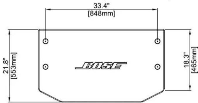
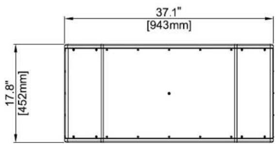
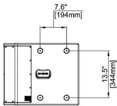
| Physical Dimensions (H x W x D), inches 17.8 x 37.1 x 21.8 in (452 x 943 x 553 mm) | |
| Net Weight (without Bose RMSFLY accessory) | 132 lbs |
| Net Weight (with Bose RMSFLY accessory) | 168 lbs |
| Connectors | 2 x Neutrik® NL4 |
Product Dimensions (in millimeters)
Connector Wiring
The RoomMatch™ subwoofer is equipped with two (2) Neutrik® NL4 connectors wired in parallel to allow loop-through connection to an additional subwoofer. The connector is factory wired to provide discrete amplifier channel drive to each of the woofers as follows:
| NL4 Connector Pin Driver Bandpass Section | |
| 1+ Driver-1 positive | |
| 1 - Driver-1 negative | |
| 2+ Driver-2 positive | |
| 2 - Driver-2 negative |
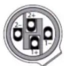
Neutrik*NL4
Recommended Amplifier Power
Each 15-inch transducer of the RMS215 subwoofer features a long-term power-handling rating of 500 watts, with a transient peak rating of 2,000 watts. Selecting the proper amplifier size for a given loudspeaker requires analysis of the transducer long-term (or RMS) power rating, dynamic range of the input-source material (crest factor), desired sound pressure levels, and other factors. As a general guideline, to maximize the performance of the RMS215 subwoofer, we recommended using two (2) channels of amplifier power, each rated to deliver 1,000 watts into a nominal 8-ohm load.
| RMS215 Transducer Nominal Impedance Amp Channel Amp Power Rating | ||
| Driver-1 8 ohms 1 500 to 1000 watts | ||
| Driver-2 8 ohms 2 500 to 1000 watts | ||
The Bose® PowerMatch™ PM8500 Professional Amplifier (sold separately) is easily configured to provide the recommended amplifier power for the RMS215 subwoofer. It also provides presets for recommended signal processing, including several cardioid bass array settings.
Recommended Signal Processing
Digital signal processing (DSP) equipment is required for infrasonic protection, crossover, equalization, and protection limiting functions. The recommended processing for subsonic protection is a high-pass filter with center frequency of 40Hz and a roll-off slope of at least 12-dB per octave (2nd order filter).
The recommended crossover frequency for the RMS215 subwoofer ranges from 80Hz to 200Hz , depending on the response of your mid/high-frequency loudspeaker system. In general, we recommend using 24-dB per octave (4th order filter) crossover slopes between the RMS215 subwoofer and your mid/high-frequency system.
The Bose ControlSpace ESP (sold separately) provides presets for the RMS215 subwoofer and provides all required digital signal processing, including processing for several cardioid bass array configurations.
Attaching Bose RMSFLY Side-Plate Rigging Kit
The RoomMatch™ RMS215 subwoofer is shipped with no array rigging hardware. The optional RoomMatch™ RMSFLY accessory part (343856-0110) is available to facilitate integration of the RMS215 subwoofer in RoomMatch™ Arrays. The RMSFLY side-plate hardware is not required for floor or ground-stack installations of RMS215 subwooers. To attach the RMSFLY side-plate rigging hardware to the RMS215 subwoofer, follow these steps:
1) Remove RMS215 subwoofer from the shipping carton, remove packing materials, and place the subwoofer on the floor beneath planned suspension point.
2) Remove the eight flat-head screws using a 5.5mm hex key on the left and right sides of the subwoofer (four per side). Included foam washers under the inserts should remain affixed to the subwoofer.
3) Insert M10 x 40 mm fasteners through individual side-plates, and supplied flat washers, and then into the subwoofer inserts, tightening by hand as shown in Figure 2. Note the Left and Right part markings for side-plates. After both side-plates are attached, the RMS215 subwoofer is ready for integration with other RoomMatch™ modules in full-range arrays.
4) Attach the subwoofer/side-plate assembly to its associated array frame or upper subwoofer and tighten bolts by hand to facilitate alignment. After all bolts are in place, perform final tightening using torque not to exceed 35 to 40 foot-pounds (47 to 54 Newton-meters).
NOTE: U-Shaped side-plate channel faces upward, the raised mounting bosses face the cabinet, and the oblong alignment slot at the base of the side-plate points toward the front of the loudspeaker.
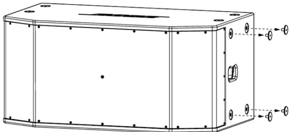
Figure 1. Remove flat-head screws

Figure 2. Attach side-plate with supplied bolts
NOTE: When using the RMS215 subwoofer with other Bose RoomMatch™ Array Module loudspeakers, thread the supplied Array Module handles into each RMSFLY side-plate upper center hole to aid in lifting/moving the subwooers. Remove the handles after positioning the subwoofer, before final tightening of bolts and elevating the array.
For additional information regarding the design and installation of RoomMatch™ arrays, please refer to the pro.Bose.com website to download the document RoomMatch™ Array Design and Installation Guide.
Visit us on the web at pro.Bose.com.
Americas
(USA, Canada, Mexico, Central America, South America)
Bose Corporation
The Mountain
Framingham, MA 01701 USA
Corporate Center: 508-879-7330
Americas Professional Systems,
Technical Support: 800-994-2673
Australia
Bose Pty Limited
Unit 3/2 Holker Street
Newington NSW Australia
61287379999
Belgium
Bose N.V. / S.A
Limesweg 2,03700
Tongeren, Belgium
012-390800
China
Bose Electronics (Shanghai) Co Ltd
36F, West Gate Tower
1038 West Nanjing Road
Shanghai, P.R.C. 200041 China
86 21 6271 3800
France
Bose S.A.S
1 Matheson Street, Causeway Bay, Hong Kong
852 2123 9000
India
Bose Corporation India Private Limited
4th Floor, Shriram Bhartiya Kala Kendra
1, Copernicus Marg
New Delhi 110001, India
91 11 23073825
Italy
Bose SpA
Via Della Magliana 87600148
Rome, Italy
066-5670802
Japan
Bose K.K., Shibuya YT Building
28-3 Maruyama-sho
Shibuya-ku, Tokyo 150
TEL 3-5489-0955
www.bose.co.jp
The Netherlands
Bose BV
1 Ambley Green, Gillingham Business Park
KENT ME8 ONJ
Gillingham, England
0870-741-4500
See website for other countries