Dashboard 100 - Counter Bell - Free user manual and instructions
Find the device manual for free Dashboard 100 Bell in PDF.
Frequently Asked Questions - Dashboard 100 Bell
User questions about Dashboard 100 Bell
0 question about this device. Answer the ones you know or ask your own.
Ask a new question about this device
Download the instructions for your Counter in PDF format for free! Find your manual Dashboard 100 - Bell and take your electronic device back in hand. On this page are published all the documents necessary for the use of your device. Dashboard 100 by Bell.
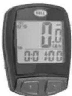
USER MANUAL Dashboard 100 Bell

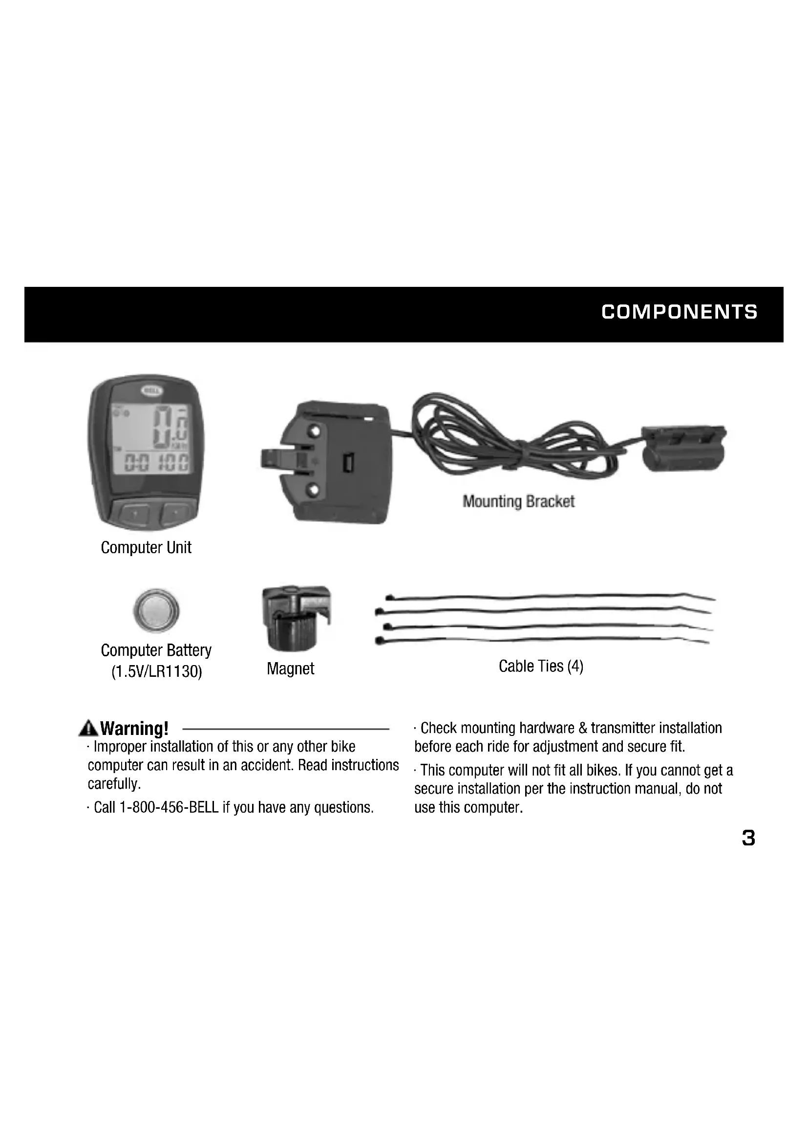
Computer Battery (1.5V/LR1130)
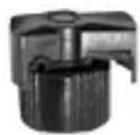
Magnet

Cable Ties (4)
Warning!
- Improper installation of this or any other bike computer can result in an accident. Read instructions carefully.
-
Call 1-800-456-BELL if you have any questions.
-
Check mounting hardware & transmitter installation before each ride for adjustment and secure fit.
- This computer will not fit all bikes. If you cannot get a secure installation per the instruction manual, do not use this computer.
INSTALLATION
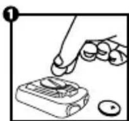
STEP 1: Install the Battery - Remove the battery cover from the bottom of the computer using a small coin (Figure 1). Install the computer battery (1.5V/LR1130) with the positive (+) pole facing up. Replace the battery cover and tighten. Note: Replacing the battery will erase all stored information. When installing a new battery after having used the computer, make sure to write down the odometer value before changing the battery so you can later re-enter it in the computer.
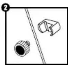
STEP 2: Install the Magnet to the Wheel - Clamp the magnet to a spoke on the right side of the front wheel (Figure 2). Make sure that the magnet is facing the outside of the wheel so that the flat side of the magnet passes in front of the sensor.
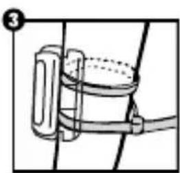
STEP 3: Attach the Sensor to the Fork - Attach the computer sensor to the right fork leg using two of the cable ties provided. Make sure the metal side of the sensor is facing the wheel. Do not fully secure the cable ties yet, as the sensor location may require further adjustment (Figure 3). Adjust the sensor and magnet location so that clearance between the two is no greater than 2mm . (Figure 4). The magnet should now pass by the tip of the sensor when the wheel rotates.
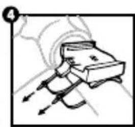
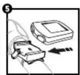
STEP 4: Install the Mounting Bracket & Computer—Attach the mounting bracket to the handlebar by using the remaining 2 cable ties as shown in (Figure 4). Make sure the mounting bracket is clamped tightly and will not slip on the handlebar. Insert the computer into the mounting bracket (Figure 5). When adjustments have been made and the computer operates correctly, tighten completely all nuts and bolts.
PROGRAMMING THE COMPUTER
STEP 1: Set the Wheel Value- First, using the table provided, determine the correct, 4-digit, wheel value based on the size of your tire. The wheel value is the distance in millimeters per one revolution of the wheel. Next, press and hold the left and right button for two seconds. The preset value "2124" should appear with the digit "4" flashing. Press the right button to modify the digit to the correct setting. Once correct digit is shown, press the left button to move to the next digit. Repeat until all four digits are set to the correct wheel value for your bike.
Road Bike
| 20" | 1596 |
| 22" | 1759 |
| 24" | 1916 |
| 26" | 2073 |
| 27"/700c | 2124 |
| 28" | 2237 |
Mountain Bike
| 24" | 1888 |
| 26" | 2045 |
| 26x2.25 | 2077 |
| 27" | 2155 |
| 29x2.1 | 2288 |
| 29x2.23 | 2326 |
STEP 2: Set KM or Mile Selection - After setting the wheel value, the KM/M selection will appear. Press the RIGHT button to choose kilometer or mile selection. Press the LEFT button to confirm and proceed to Clock function.
STEP 3: Set the Clock - The clock function will appear at the bottom of the screen. Press and hold the LEFT button for 3 seconds to get a flashing "24H" symbol. Press the RIGHT button to select between 12 and 24-hour format. Press the LEFT button to confirm. Next, the hour digits will start to flash. Use the RIGHT button to select the hour and press the LEFT button to confirm. Repeat for minutes digits. Press the LEFT button once more to set the clock.
STEP 4: Test to Ensure Proper Installation – Now that the computer is programmed, insert it into the bracket. Spin the front wheel. The speed tendency icon in the upper left corner of the screen should be turning as the computer starts recording data (Refer to Troubleshooting in case of problems).
ADDITIONAL FUNCTION MODES
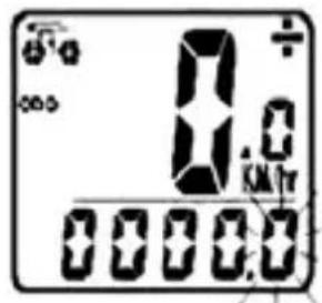
OdOMeter (OdO)- Total distance traveled is indicated by "ODO" and displayed on the bottom line. To reset ODO, press both RIGHT and LEFT buttons for 3 seconds or remove and replace the battery. Now press the RIGHT button to advance to the DST mode.
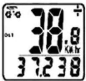
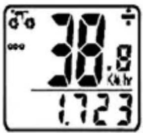
trip Meter (dSt) - Trip distance is indicated by DST and is displayed on the bottom line. The Trip Meter is activated automatically with speedometer input (comes on automatically when you begin riding, turns off when you stop). To reset DST to zero, press and hold the RIGHT and LEFT buttons for 3 seconds. Note that TM (Trip Time) & AVS (Average Speed) will also be reset at that time. Now press the RIGHT button to advance to the MXS mode.
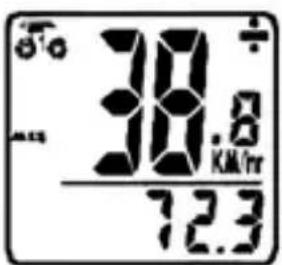
MaxiMuM Speed (MxS) - Maximum speed is indicated by MXS and is displayed on the bottom line. Maximum speed is stored in memory and updates only when a higher speed is reached. To reset MXS, press and hold the LEFT button for 3 seconds. Now press RIGHT button to advance to Average Speed (AVS) mode.
ADDITIONAL FUNCTION MODES
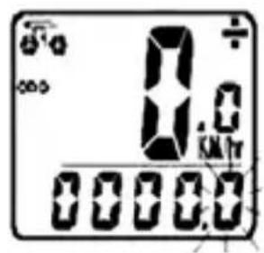
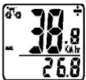
aVerage Speed (aVS) – Average speed is indicated by AVS and is displayed on the bottom line. AVS works in conjunction with the Trip Timer (TM) to calculate the average speed for a specific trip. Now press the RIGHT button to advance to the Trip Timer (TM) mode.
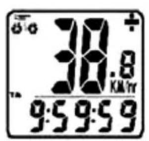
trip tiMer (tM)- Trip Timer is indicated by TM and is displayed on the bottom line. The Trip Timer is activated automatically with computer input (comes on automatically when you begin riding, turns off when you stop). It records only the time actually spent riding. To reset TM to zero, return to DST (Trip Meter) mode and reset to zero per the instructions above. Return to TM mode and press RIGHT button to advance to SCAN function
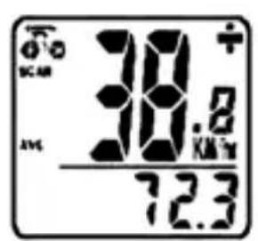
Scan - The Scan mode conveniently rotates DST, MXS, AVS, and TM readings on the computer screen without the need to press any buttons. Now press the RIGHT button to return to the Clock mode.
ADDITIONAL FUNCTION MODES
auto Stop/Start- To preserve batteries, the cycle computer will automatically switch off if the unit is left unused for over 5 to 6 minutes. Display will reappear with a press on either button or input from the sensor.
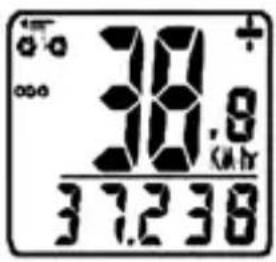
SpeedOMeter- Instantaneous Speed is indicated on the top line. The range of measurement is from 0 to 99KM / hr (0 to 99M / hr ) and accuracy is ± 0.5KM / hr (M/hr).
SpeedOMeter COMparatOr-A "+" or "-" sign appears to the right of the speed. "+" indicates you are traveling faster than your average speed (AVS). A "-" indicates you are riding slower than your average speed.
Speed tendency - A cyclist symbol appears to the left of the speed. The wheel turns forward to indicate acceleration. The wheel turns backward to indicate deceleration.
TROUBLESHOOTING
| prOBlE M | pOSSiBlc CauSe | reCOMMended aCtiOn |
| No speedometer display and/or no data reading | Possible interference from electrical sourcesImproper magnet/sensor alignmentPoor battery contact or low/dead battery | Move computer to different areaEnsure speedometer sensor and magnet are properly installed and aligned (p.3)Replace Battery |
| Slow display response | Temperature outside of operational limits (0-60°C or 32-140°F) | Only use computer when temperature is within operational limits |
| Display shows irregular features | Poor battery contact or low/dead battery | Replace battery |
| Black display | Temperature too hot or display exposed to sunlight too longComputer damaged or dropped | Only use computer when temperature is within operational limits. Remove from sunlightComputer is broken |
| No trip distance reading | Improper sensor/magnet alignment Ensure proper alignment |
COMPOSANTS
Ordinateur