EZFit - Counter Bell - Free user manual and instructions
Find the device manual for free EZFit Bell in PDF.

Frequently Asked Questions - EZFit Bell
User questions about EZFit Bell
0 question about this device. Answer the ones you know or ask your own.
Ask a new question about this device
Download the instructions for your Counter in PDF format for free! Find your manual EZFit - Bell and take your electronic device back in hand. On this page are published all the documents necessary for the use of your device. EZFit by Bell.
USER MANUAL EZFit Bell
■ Improper installation of this or any other bike computer can result in an accident. Read and follow installation instructions carefully.
Call our toll free customer service department at 1-800-456-BELL if you have any questions about installation.
Check mounting hardware and transmitter installation before each ride for adjustment and secure fit.
This computer will not fit all bikes. If you cannot get a secure installation per the instruction manual, do not use this computer.
!aDvERTENCla!
English Instructions 4
Computer Battery (1.5V/186/LR43)
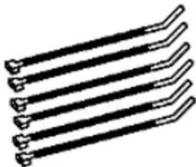
Cable TiesComputer Unit
BaTTERy INSTaIIaTION
Remove the battery cover from the bottom of the computer using a coin. Install the battery with the positive (+) pole facing out (Figure 1) and replace the cover. Should the computer screen show irregular figures, take out the battery and install again. This will clear and restart the computer.
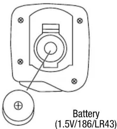
Figure 1
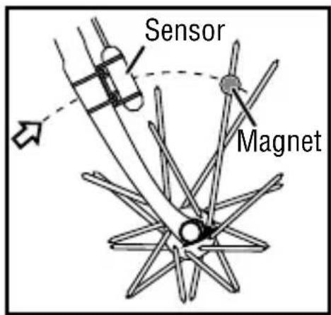
MAGNET AND SENSOR INSTALLATION
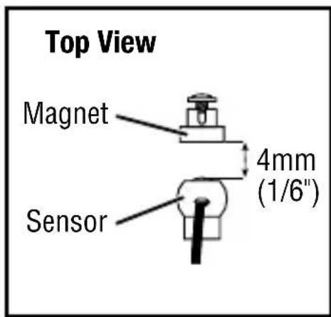
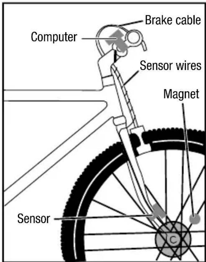
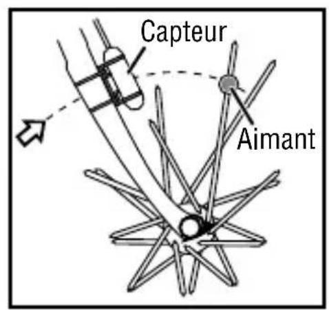
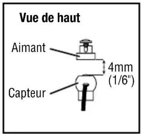
Attach the speedometer sensor on the right fork of the front wheel using the cable tie. Clamp the magnet on a spoke on the right side of the front wheel (Figure 2). Adjust the position of the magnet so that when the wheel spins, the magnet will pass in front of the lower section of the sensor (Figure 3). Clearance between magnet and sensor should not be greater than 1/6'' (4mm) (Figure 4). Once it is well positioned, tighten the magnet on the spoke.
Note: Overtightening the screws can strip the threads or crack the assembly, so use caution.
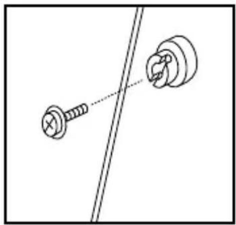
Figure 2 Figure 4Figure 3
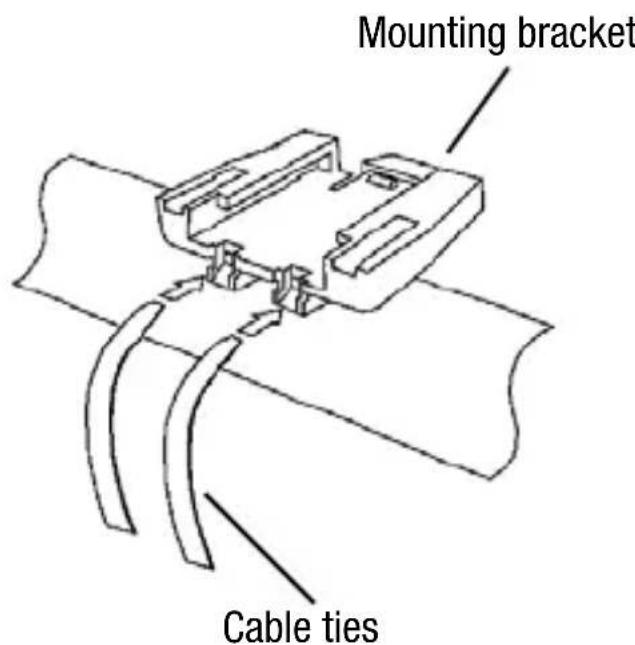
MOUNTING BRaCkET
Attach the mounting bracket to the handlebar by using two cable ties as shown. Make sure the mounting bracket is clamped tightly and will not slip on the handlebar.
Bracket can be attached to either the left or right hand side of the handlebar.
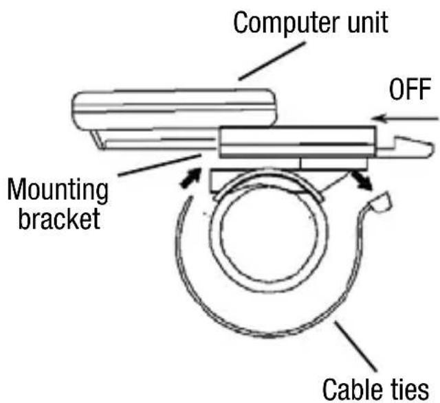
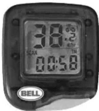
COMPUTER
Slide computer into mounting bracket, toward seat until it is inserted all the way into the bracket. To check for proper installation, spin the front wheel when the computer is in speedometer mode (see next pages for speedometer mode set-up). The speed should appear on the screen.
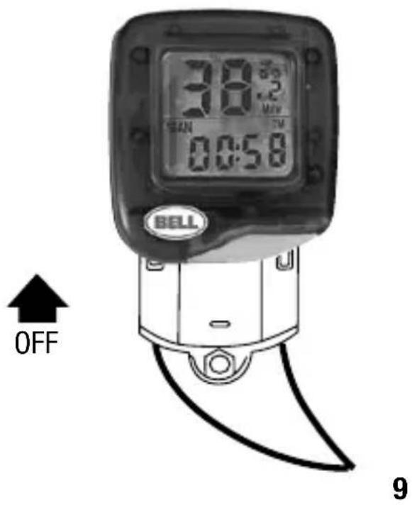
IMPORTANT: To remove computer from mounting bracket, wrap forefinger around the front of the mounting bracket and push the computer away from you with your thumb.
SENSOR WIRING
Route the sensor wire up the fork blade, using the cable ties to secure it at the bottom and crown. Wire must not hang loosely. Leave enough slack to allow wheel to turn right and left freely. Route the remaining wire around the front brake cable and to the handlebar. Excess wire should be carefully looped and secured to the stem with a cable tie.
Note: Make sure cable tie ends are cut so as to not interfere with operation of bicycle.
WhEEI SizE INPUT
After installing the battery, a default wheel factor will appear with the last digit scrolling. Use the Wheel Diameter Size Chart on the next page to find the correct wheel factor (c). In the event your tire size is not included in this chart, multiply your wheel diameter (d) in millimeters by 3.1416 to determine the correct wheel factor (c).
To enter the correct wheel factor into the computer, each digit will need to be set individually. Press the button when the correct digit for your wheel factor appears. This will lock in the correct digit and the next digit to the left will begin to scroll. Repeat until all four correct digits are entered.
To return to the Wheel Size Input screen, remove the battery or push and hold the button for two seconds when in Odometer (OD0) mode.
Note: All functions will be reset at that time.
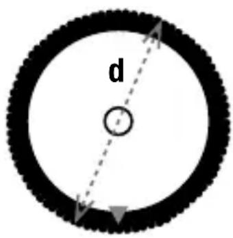
d is the diameter of wheel in millimeters
WHEEL DIAMETER SIZE CHART
| Wheel Wheel Diameter (d) Factor (c) |
| 20" 1596 |
| 22" 1759 |
| 24" 1916 |
| 26" (650A) 2073 |
| 26.4" (700 x 20C) 2107 |
| 26.5" (Tubular) 2117 |
| 26.6" (700 x 25C) 2124 |
| 26.8" (700 x 28C) 2136 |
| Wheel Wheel Diameter (d) Factor (c) | |
| 27" (700 x 32C) 2155 | |
| 27" x 1.25 2155 | |
| 28" (700B) 2237 | |
| ATB 24" x 1.75 | 1888 |
| ATB 26" x 1.4 | 1995 |
| ATB 26" x 1.5 | 2030 |
| ATB 26" x 1.75 | 2045 |
| ATB 26" x 2 (650B) | 2099 |
km/MIIE SELECTION
After wheel size input, the KM/MILE selection screen will appear with KM and Mile flashing alternately. Press the button while desired mode appears in the screen to lock it in. The unit is then switched to speedometer mode and is now ready for use.
FUNCTION NavlgaTION
The speedometer is now ready to use. Press the button to move between the available functions.
aUTO STaRT/STOP
To preserve the battery, the cycle computer will automatically switch off if the unit is stopped or left unused for more than 5 minutes. The display will reappear when the button is pressed or when the unit detects input from the sensor.
SPEEDOMETER
Instantaneous Speed is indicated on the top line. The range of measurement is from 0 to 99M / hr (0 to 99KM / hr ) and the accuracy is +/- 0.5 M/hr (KM/hr).
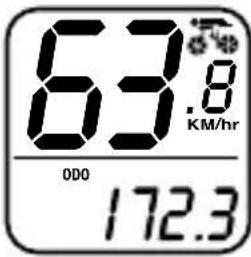
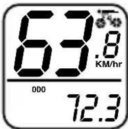
ODOMETER (ODO)
Total Distance travelled is indicated by ODO and displayed on the bottom line. To reset the Odometer, press and hold the button for two seconds when in ODO mode or remove the battery.
Note: Resetting the Odometer will reset all funtions to zero, and will also require re-entering the Wheel Size.
Press the button to enter Trip Distance (DST) mode.
TRIP DISTANCE (DST)
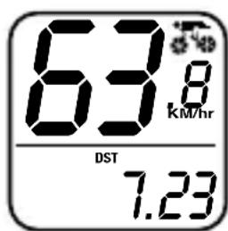
Trip Distance is indicated by DST and is displayed on the bottom line. Trip Distance is activated automatically with speedometer input. To reset the Trip Distance, press and hold the button for two seconds when in DST mode.
Note: Resetting the Trip Distance will also reset the Trip Timer (TM) to zero.
Press the button to enter Trip Timer (TM) mode.
TRIP TIMER (TM)
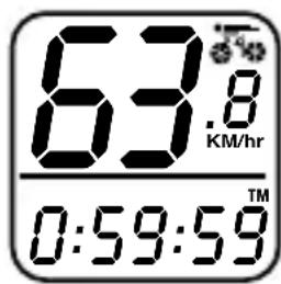
Trip Timer is indicated by TM and is displayed on the bottom line. Trip Timer is activated automatically with speedometer input (on when you ride and off when you stop). It records only the time spent actually riding. To reset the Trip Timer to zero, press and hold the button for two seconds when in DST mode.
Press the button to return to Odometer (ODO) mode.
TROUBLESHOOTING
PROBLEM CAUSE
| No speedometer reading | Improper magnet/sensor alignment or dead battery or computer not inserted all the way into mounting bracket. |
| Slow display response | Temperature outside of operating limits (0–55 degrees C or 32–130 degrees F). |
| Black display | Temperature too hot, or display exposed to direct sunlight too long. |
| Display readout fades or shows the wheel size setting mode abnormally | Poor battery contacts or low/dead battery. |
| No trip distance reading | Improper magnet/sensor alignment or dead battery or computer not inserted all the way into mounting bracket. |
| Display shows irregular figures | Poor battery contacts or low/dead battery. |
NOTES
FUNCTIONES
■ Velocimetro 0-99.9 KM/hr o M/hr
Odometro (ODO) 0-9999 KM o M
Distancia del viaje (DST) 0-999.99 KM o M
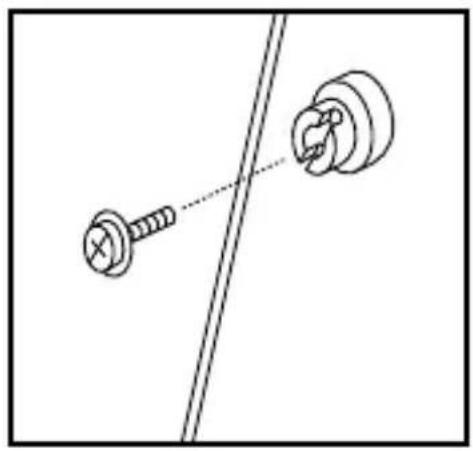
Figure 2 Figure 4Figure 3
SUPPORT DE MONTagE
© 2006 Bell Sports, Inc., Rantoul, IL 61866
Tel: 1-800-456-BELL www.bellbikestuff.com