SpinFit - Counter Bell - Free user manual and instructions
Find the device manual for free SpinFit Bell in PDF.
| Product type | Bike computer |
| Brand | Bell |
| Model | SpinFit |
| Power supply | 1.5 V battery type L1142 |
| Display | LCD with multiple functions |
| Current speed (SPD) | 0 to 199.9 km/h or mph |
| Average speed (AVS) | 0 to 199.9 km/h or mph |
| Maximum speed (MXS) | 0 to 199.9 km/h or mph |
| Speed comparison | Yes (+ or -) |
| Trip distance (DST) | 0 to 999.99 km or miles |
| Odometer (ODO) | 0 to 9999 km or miles |
| Trip time (TM) | 0 to 9h59m59s |
| Calorie counter (CAL) | 0 to 999 calories |
| Clock | 12h or 24h format |
| Units | km/miles, kg/lbs |
| Auto power on | Stops after 5 min inactivity, wakes on movement |
| Low battery indicator | Yes |
| Mounting | Handlebar bracket with rubber straps |
| Sensor | Front fork attachment, max gap 5 mm from magnet |
| Programmable wheel size | Yes, via table or calculation (diameter × 3.1416) |
| Programmable user weight | 35-199 kg or 80-499 lbs |
| Safety | Check installation before each use; do not overtighten screws |
| Maintenance | Clean with soft cloth; protect from prolonged sun |
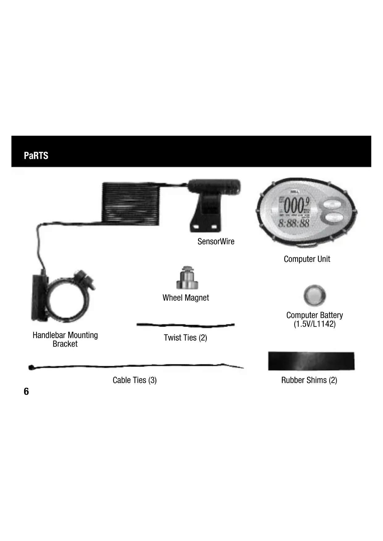
| Included parts | Main unit, sensor, magnet, handlebar bracket, cable ties (3), rubber straps (2), L1142 battery |
Frequently Asked Questions - SpinFit Bell
User questions about SpinFit Bell
0 question about this device. Answer the ones you know or ask your own.
Ask a new question about this device
Download the instructions for your Counter in PDF format for free! Find your manual SpinFit - Bell and take your electronic device back in hand. On this page are published all the documents necessary for the use of your device. SpinFit by Bell.
USER MANUAL SpinFit Bell
- Improper installation of this or any other bike computer can result in an accident. Read and follow installation instructions carefully.
■ Call our toll free customer service department at 1-800-456-BELL if you have any questions about installation.
■ Check mounting hardware and transmitter installation before each ride for adjustment and secure fit.
This computer will not fit all bikes. If you cannot get a secure installation per the instruction manual, do not use this computer.
! aDvERTENCIa!
English Instructions 4
FUNCTIONS SUMMaRy ....5
INSTALLATION
Parts....6
Magnet and Sensor ....7
Handlebar Mounting Bracket 8
Sensor Wiring 9
COMPUTER CONFIgURaTION
Battery Installation....10
Wheel Size Input....11
Wheel Diameter Size Chart....12
Unit Selection (Distance, Time, Weight)....13
Weight Input 14
USagE
Quickstart....15
Auto Start/Stop, Low Battery Indicator, Basic or Advanced Display....16
Speed Functions: SPD, AVS, MXS, Speed Comparison....17
Calorie Function: CAL....18
Distance Functions: DST, ODO 19
Time Functions: Clock, TM....20
Reset Functions - Front 21
Reset Functions - Back....22
TROUblEShOOTINg....23
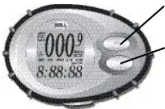
FUNCTIONS SUMMaRy
text_image
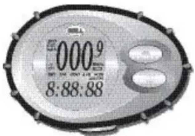
000⁹ 8:88:88■ Current Speed (SPD)
■ Calories Burned (CAL)
■ Trip Distance (DST)
■ Trip Timer (TM)
■ Odometer (ODO)
■ Average Speed (AVS)
■ Maximum Speed (MXS)
■ 12 or 24 Hour Clock
■ Current-to-Average Speed Comparison (+ or −)
■ Auto Start/Stop
■ Basic or Advanced Display
■ Unit Selection (Mile or Km, Kgs or Lbs)
■ Low Battery Indicator
■ New Trip Function Reset
PaRTS
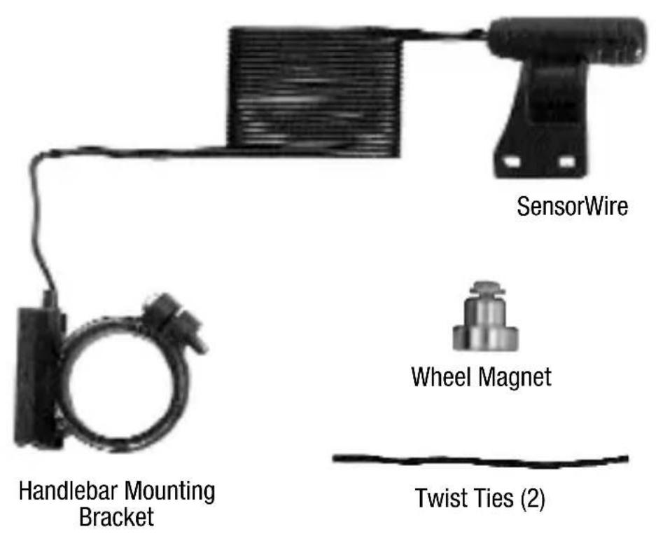
text_image
SensorWire Wheel Magnet Handlebar Mounting Bracket Twist Ties (2)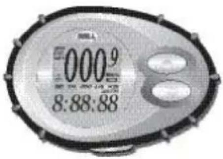
text_image
0009 8:88:88Computer Unit

Computer Battery (1.5V/L1142)

Rubber Shims (2)
INSTALLATION - MAGNET AND SENSOR
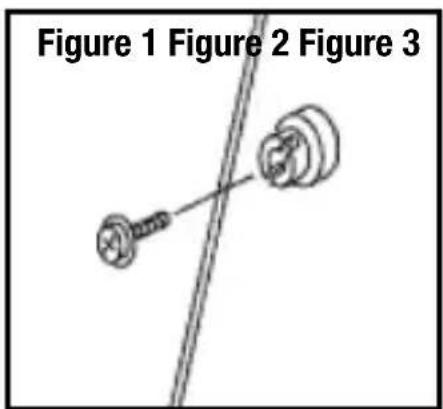
Attach the speedometer sensor on the right fork of the front wheel using two of the cable ties provided. Make sure the sensor is curved toward the wheel, and that the smooth side of the cable tie is facing out. Do not fully secure the cable ties yet, as the sensor location might require some later adjustments (Figure 2).
Clamp the round magnet on a spoke on the right side of the front wheel (Figure 1). Adjust the position of the magnet so that when the wheel spins, the flat side of the magnet passes in front of the sensor (Figure 2).
Adjust the sensor and magnet location so that clearance between magnet and sensor is not greater than 1/5" (5mm) (Figure 3). Once well positioned, secure the cable ties on the fork and tighten the magnet screw on the spoke.
Note: Use caution when tightening the screw on the spoke as overtightening can strip the threads.
text_image
Figure 1 Figure 2 Figure 3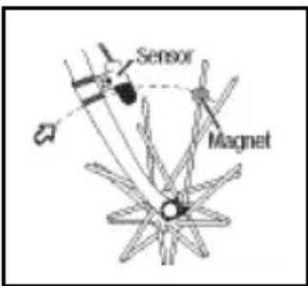
text_image
Sensor Magnet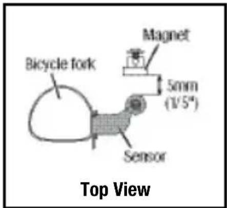
text_image
Bicycle fork Magnet 5mm (1/5") Sensor Top ViewINSTallaTION - haNDIEbaR MOUNTING bRaCkET
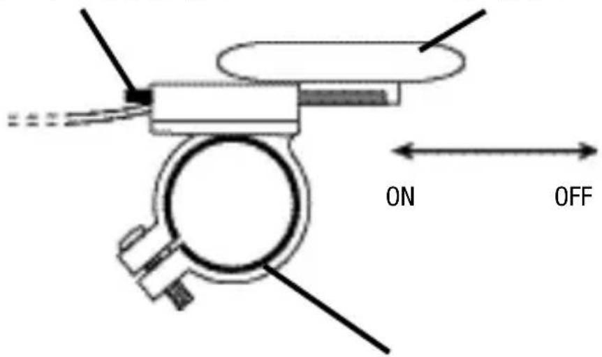
Attach the mounting bracket to the handlebar with cord facing toward seat. If necessary, use the rubber shims provided to obtain a secure fit on the handlebar. Note that there is a rubber shim already glued inside the clamp that can easily be removed if needed.
Bracket can be attached to either the left or right hand side of the handlebar.
Push button down to remove computer
Computer Unit
text_image
ON OFFShims will prevent slipping
INSTALLATION - SENSOR WIRING
Route the sensor wire up the fork blade, using the twist ties to secure it at the bottom and crown. Wire must not hang loosely. Leave enough slack to allow wheel to turn right and left freely. Route the remaining wire around the front brake cable and to the handlebar. Excess wire should be carefully looped and secured to the stem with a twist tie.
Note: Make sure twist ties do not interfere with safe operation of bicycle.
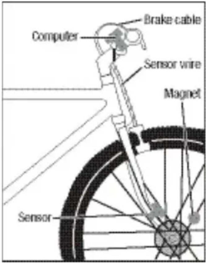
text_image
Brake cable Computer Sensor wire Magnet SensorbATTERy INSTallATION
Remove the battery cover from the back of the computer using a coin. Install the battery with the positive (+) pole facing out and replace the cover. Should the computer screen show irregular figures, take out the battery and install again. This will clear and restart the computer.
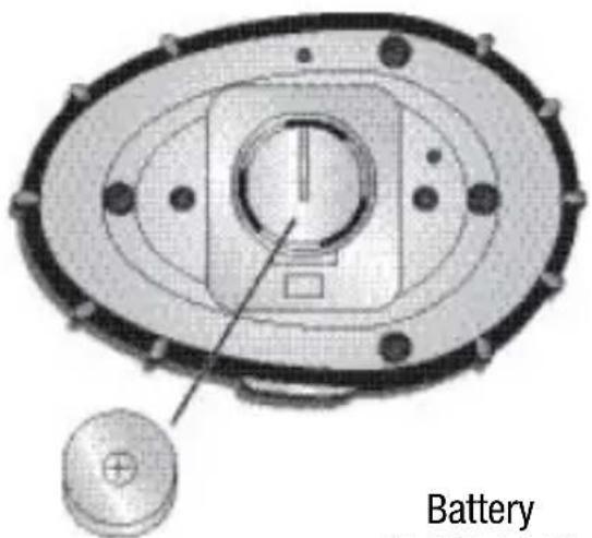
text_image
Battery(1.5V/L1142)
WHEEL SIZE INPUT
After installing the battery, the default wheel factor '2124' will appear with the digit furthest to the right blinking. This is the correct setting for a 26.6" (700 x 25C) tire. If this is your wheel size, press the upper button four times to confirm each one of the four digits. If this is not your wheel size, use the Wheel Diameter Size Chart on the next page to find the correct wheel factor (c). In the event your tire size is not included in this chart, multiply your wheel diameter (d) in millimeters by 3.1416 to determine the correct wheel factor (c).
To enter the correct wheel factor into the computer, press the lower button until the correct digit appears. Press the upper button to lock in the correct digit. Repeat until all four correct digits are entered. To return to the Wheel Size Input screen at any time, push the MAJOR FUNCTION reset button on the back of the computer (see RESET FUNCTIONS - BACK section).
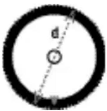
text_image
d rd is the diameter of wheel in millimeters
WHEEL DIAMETER SIZE CHART
| Wheel Wheel Diameter (d) Factor (c) | |
| 20" | 1596 |
| 22" | 1759 |
| 24" | 1916 |
| 26" | (650A) 2073 |
| 26.4" | (700 x 20C) 2107 |
| 26.5" | (Tubular) 2117 |
| 26.6" | (700 x 25C) 2124 |
| 26.8" | (700 x 28C) 2136 |
| Wheel Wheel Diameter (d) Factor (c) | |
| 27" (700 x 32C) 2155 | |
| 27" x 1.25 2155 | |
| 28" (700B) 2237 | |
| ATB 24" x 1.75 | 1888 |
| ATB 26" x 1.4 | 1995 |
| ATB 26" x 1.5 | 2030 |
| ATB 26" x 1.75 | 2045 |
| ATB 26" x 2 (650B) | 2099 |
KM OR MILE SELECTION
After wheel size input, the KM/M selection screen will appear. Press the dower button to choose between Kilometer (KM) and Mile (M). Press the upper button to confirm choice.
12 OR 24 HR FORMAT SELECTION
After Km or Mile Selection, the clock format screen will appear. Press the lower button to choose between 12 hour or 24 hour format. Press the upper button to confirm choice.
KG OR LB SELECTION
After the clock format selection, the Kg/Lb selection screen will appear. Press the lower button to choose between Kilograms (Kg) and Pounds (Lbs). Press the upper button to confirm choice.
Note: To modify your selection at any time, push the MAJOR FUNCTION reset button on the back of the computer (see RESET FUNCTIONS - BACK section).
WEIghT INPUT
Once the Weight unit is selected, the computer will ask the user to enter his/her weight. This will allow the computer to accurately estimate the number of Calories Burned while riding.
To enter the correct weight, press the lower button until the correct digit appears. Press the upper button to lock in the correct digit. Repeat until all digits are entered.
Note: The weight entered should be between 80–499 Lbs or 35–199 Kgs.
The computer is now in speedometer mode and is ready for use.
QUICKSTART
Now that the computer is configured, slide the computer into the mounting bracket toward bike seat until it is inserted all the way into the bracket. To check for proper installation, spin the front wheel. The data recording wheel icon to the left of the screen should be turning as the computer starts recording data (Refer to TROUBLESHOOTING section in case of problems).
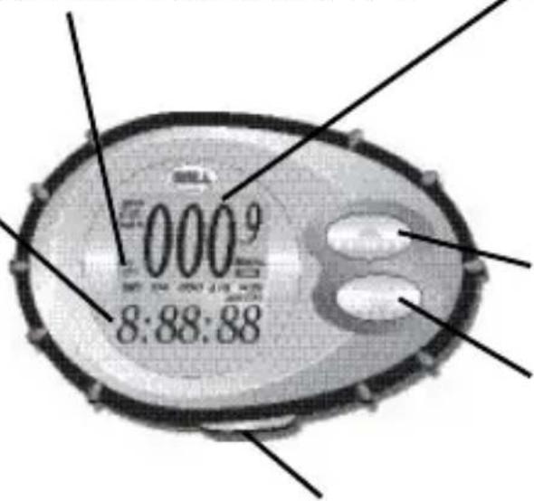
Current-to-Average Speed Comparison (+ or -)
LOWER SCREEN
Trip Distance (DST)
0–999.99 KM or M
Trip Timer (TM)
9 hrs 59 min 59 sec
Total Distance (ODO)
0–9999 KM or M
Average Speed (AVS)
0–199.9 KM/hr or M/hr
Maximum Speed (MXS)
0–199.9 KM/hr or M/hr
Clock
text_image
000 9 8:88:88BASIC or ADVANCED Display
UPPER SCREEN
Current Speed (SPD)
0–199.9 KM/hr or M/hr
Calories Burned (CAL)
0–999 Calories Burned
Controls UPPER SCREEN
Controls LOWER SCREEN
AUTO START/STOP, LOW BATTERY, BASIC or ADVANCED DISPLAY
AUTO START/STOP
To preserve the battery, the computer will automatically switch off if it is left unused for more than five minutes. The display will reappear when either button is pressed or when the unit detects input from the sensor.
LOW BATTERY INDICATOR
The low battery indicator will be displayed to the right of the screen when the remaining battery lifetime is approximately two months or less.
BASIC OR ADVANCED DISPLAY
By pressing the button on the side of the computer, user can switch between Advanced or Basic Display.
Advanced Display will make all functions available for display.
Basic Display will hide the following functions: Average Speed, Maximum Speed and Speed Comparison.
Note: Although hidden, Average Speed and Maximum Speed are still being recorded when in the Basic
SPEED FUNCTIONS: SPD, avS, MXS, SPEED COMPaRISON
CURRENT SPEED (SPD)
Current Speed represents Instantaneous Speed. It is displayed on the upper screen.
avERagE SPEED (avS)
Average Speed is displayed on the lower screen. Average Speed represents the average speed while riding.
Average Speed can be reset at any time by pressing the lower button for two seconds when avS is displayed on the screen.
Note: Resetting Average Speed will automatically reset Trip Timer and Trip Distance.
MaXIMUM SPEED (MXS)
Maximum Speed is displayed on the lower screen. Maximum Speed is stored in the computer memory and is updated only when a higher speed is reached.
Maximum Speed can be reset at any time by pressing the lower button for two seconds when MXS is displayed on the screen.
SPEED COMPaRISON (+ OR -)
Speed Comparison represents the difference between the Current Speed and the Average Speed. If the Current Speed is higher than the Average Speed, a ‘+’ sign is displayed on the screen. If the Current Speed is lower than the Average Speed, a ‘−’ sign is displayed on the screen.
CalORIE FUNCTION: Cal
Calories Burned is displayed on the upper screen. It represents the accumulated number of calories burned while riding. Calories Burned is estimated based on the following information:
User's weight
Time spent riding
Average speed
The Calorie Count on the screen will start over once 999 Calories have been burned.
Calories Burned can be reset at any time by pressing the upper button for two seconds when Cal is displayed on the screen.
DISTaNCE FUNCTIONS: DST, ODO
TRIP DISTaNCE (DST)
Trip Distance is displayed on the lower screen. Trip Distance is activated automatically with bike motion.
Trip Distance can be reset at any time by pressing the lower button for two seconds when DST is displayed on the screen.
Note: Resetting Trip Distance will automatically reset Trip Timer and Average Speed.
ODOMETER (ODO)
Odometer is displayed on the lower screen. Just like a car's odometer, ODO records the total distance ridden over time.
When changing computer battery, Odometer can be reset to previous value by pressing the flower button for two seconds when ODO is displayed on the screen.
TIME FUNCTIONS: CLOCK, TM
CLOCK
The clock can be reset at any time by pressing the lower button for two seconds while the clock is displayed on the lower screen. To enter the correct time, press the lower button until the correct digit appears. Press the upper button to lock in the correct digit. Repeat until all digits are entered.
TRIP TIMER (TM)
Trip Timer is displayed on the lower screen. Trip Timer is activated automatically with bike motion: it is on when you ride and off when you stop.
Trip Timer can be reset at any time by pressing the lower button for two seconds when TM is displayed on the lower screen.
Note: Resetting Trip Timer will automatically reset Trip Distance and Average Speed.
RESET FUNCTIONS - FRONT
text_image
0009 8:88:88INDIVIDUAL FUNCTION Reset
CAL can be reset by pressing the upper button for two seconds when in that mode.
SPD cannot be reset.
DST, TM, ODO, AVS, MXS, Clock can each be reset by pressing the lower button for two seconds when in each individual mode.
Speed Comparison cannot be reset.
NEW TRIP FUNCTION Reset
CAL, DST, TM and AVS can be reset to zero simultaneously by pressing the upper and lower buttons for two seconds. Use before you go on a new ride.
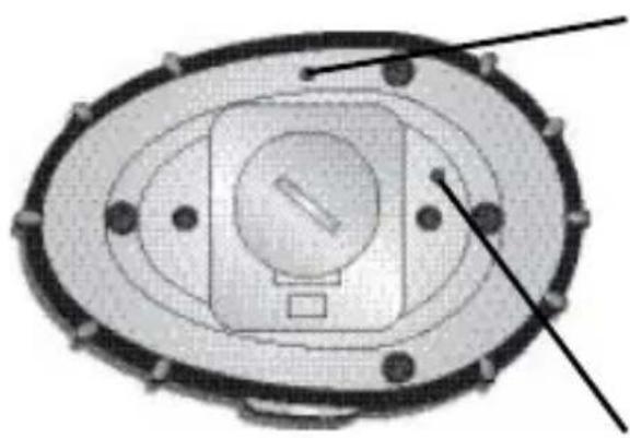
RESET FUNCTIONS - baCk
natural_image
Top-down view of a circular mechanical component with internal features and mounting holes (no text or symbols)MaJOR FUNCTION Reset
Use to clear major computer functions and settings.
Resets DST, TM, avS, MXS and Cal to zero. Does NOT reset ODO!
Asks user to reconfigure Wheel Size, Km or Mile selection, 12 or 24 hr clock format, Kg or Lb Selection, and Weight Input.
COMPUTER Reset
Use to reboot the computer in case of weird behavior or crash.
Resets DST, TM, ODO, avS, MXS and Cal to zero.
Asks user to reconfigure Wheel Size, Km or Mile selection, 12 or 24 hr clock format, Kg or Lb Selection, and Weight Input.
Notes: Make sure to write down the Odometer value before changing the battery or using the COMPUTER Reset button so that you can later re-enter it in the odometer.
The COMPUTER Reset function is equivalent to taking the computer batteries out.
TROUBLESHOOTING
PROBLEM CAUSE
| No speedometer reading and/or no data recording wheel reading | Improper magnet/sensor alignment or dead battery or computer not inserted all the way into mounting bracket. |
| Slow display response | Temperature outside of operating limits (0–55 degrees C or 32–130 degrees F). |
| Black display | Temperature too hot, or display exposed to direct sunlight too long. |
| Display readout fades or shows the ‘2124’ wheel size setting mode abnormally | Poor battery contacts or low/dead battery. |
| No trip distance reading | Improper magnet/sensor alignment or dead battery or computer not inserted all the way into mounting bracket. |
| Display shows irregular figures | Poor battery contacts or low/dead battery. |
ÍNDICE DE CONTENIDO
RESUMEN DE IaS FUNCIONES....25
INSTalaClón
Partes....26
Imán y sensor....27
text_image
Sensor Inmain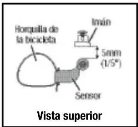
text_image
Horquilla de la bicicleta Imán 5mm (1/5°) Sensor Vista superiorINSTalaClón - abRazaDERa DE MONTaJE PaRa El TIMÓN
natural_image
Technical diagram of a mechanical component with concentric ovals and a circular base, labeled 'Pila' (no readable text or symbols beyond label)(1.5V/L1142)
natural_image
Top-down schematic of an oval-shaped mechanical or electrical component with internal components and mounting holes (no text or symbols)text_image
Figure 1 Figure 2 Figure 3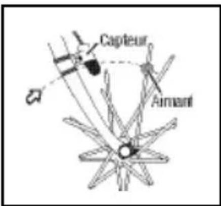
natural_image
Top-down view of a circular mechanical component with concentric layers and central slot (no text or symbols)© 2003 Bell Sports, Inc., Rantoul, IL 61866
Tel: 1-800-456-BELL www.bellbikestuff.com