
DAR 3000 - Range hood MIELE - Free user manual and instructions
Find the device manual for free DAR 3000 MIELE in PDF.

| Product type | Hood |
| Brand | Miele |
| Model | DAR 3000 |
| Available width | 600, 762, 900 mm (depending on model) |
| Installation type | Built-in in a cabinet with lowering frame |
| Operating mode | Extraction or recirculation (with DUU 151 kit) |
| Control | Manual: pull down to use, push up to store |
| Power supply | 230 V, 50 Hz (standard) |
| Safety | Respect minimum distances from the cooking surface |
| Mounting | Requires two gas springs (supplied) and flexible connection |
| Operation | Pull the handle until it clicks, slide out the baffle; after cooking, push the baffle back in and push the hood upward |
| Maintenance | Clean the baffle and filters regularly |
| Included accessories | Ultra-flexible exhaust hose, gas springs, baffle |
| Spare parts | Available from Miele |
| Repairability | Repairable by a Miele-approved professional |
| Minimum cabinet height | 480 mm (extraction mode) or 600 mm (DUU 151 recirculation mode) |
| Manual | Available for free download on notice-facile.com |
Frequently Asked Questions - DAR 3000 MIELE
User questions about DAR 3000 MIELE
0 question about this device. Answer the ones you know or ask your own.
Ask a new question about this device
Download the instructions for your Range hood in PDF format for free! Find your manual DAR 3000 - MIELE and take your electronic device back in hand. On this page are published all the documents necessary for the use of your device. DAR 3000 by MIELE.
USER MANUAL DAR 3000 MIELE
Operating and installation instructions
natural_image
Technical line drawing of a multi-tiered mechanical assembly with internal components and mounting base (no text or symbols)Bedienung
natural_image
Hand inserting a component into a device panel, showing a black arrow indicating direction (no text or symbols)natural_image
Illustration of a hand using a tool to adjust or install a mechanical component, with no visible text or symbols.natural_image
Illustration of a hand using a tool to adjust or install a mechanical component (no text or symbols visible)natural_image
Illustration of a hand interacting with a laptop screen, showing a black arrow and circular elements (no text or symbols)Please take care to read the operating and installation instructions for the cooker hood before installing the drop-down frame. Only connect it to the electricity supply when the installation of all components is complete.
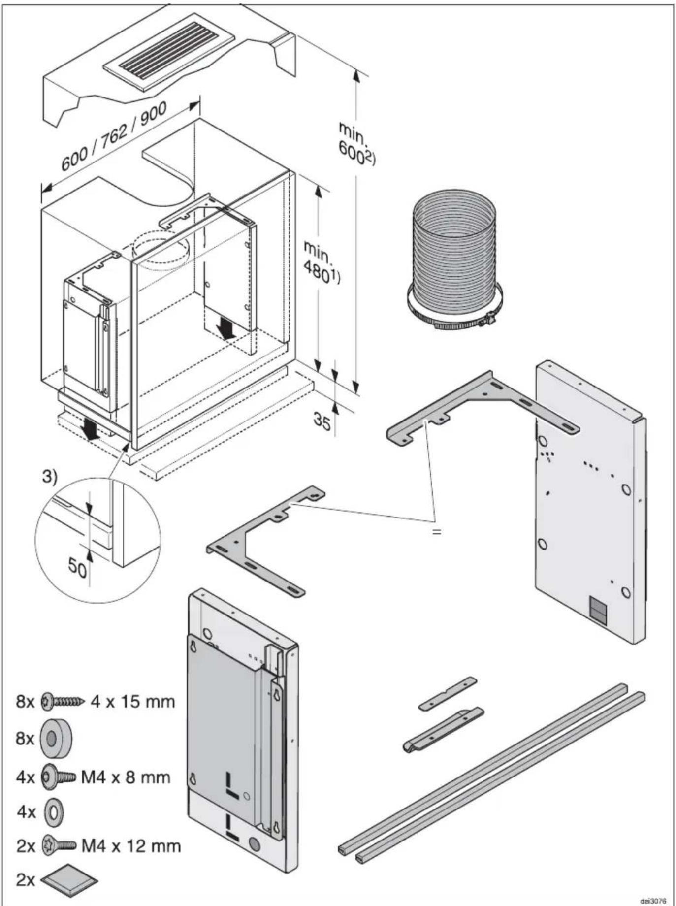
1) Unit height in extraction mode, if the air is being conducted upwards out of the unit.
2) Unit height in recirculation mode with DUU 151 recirculation kit.
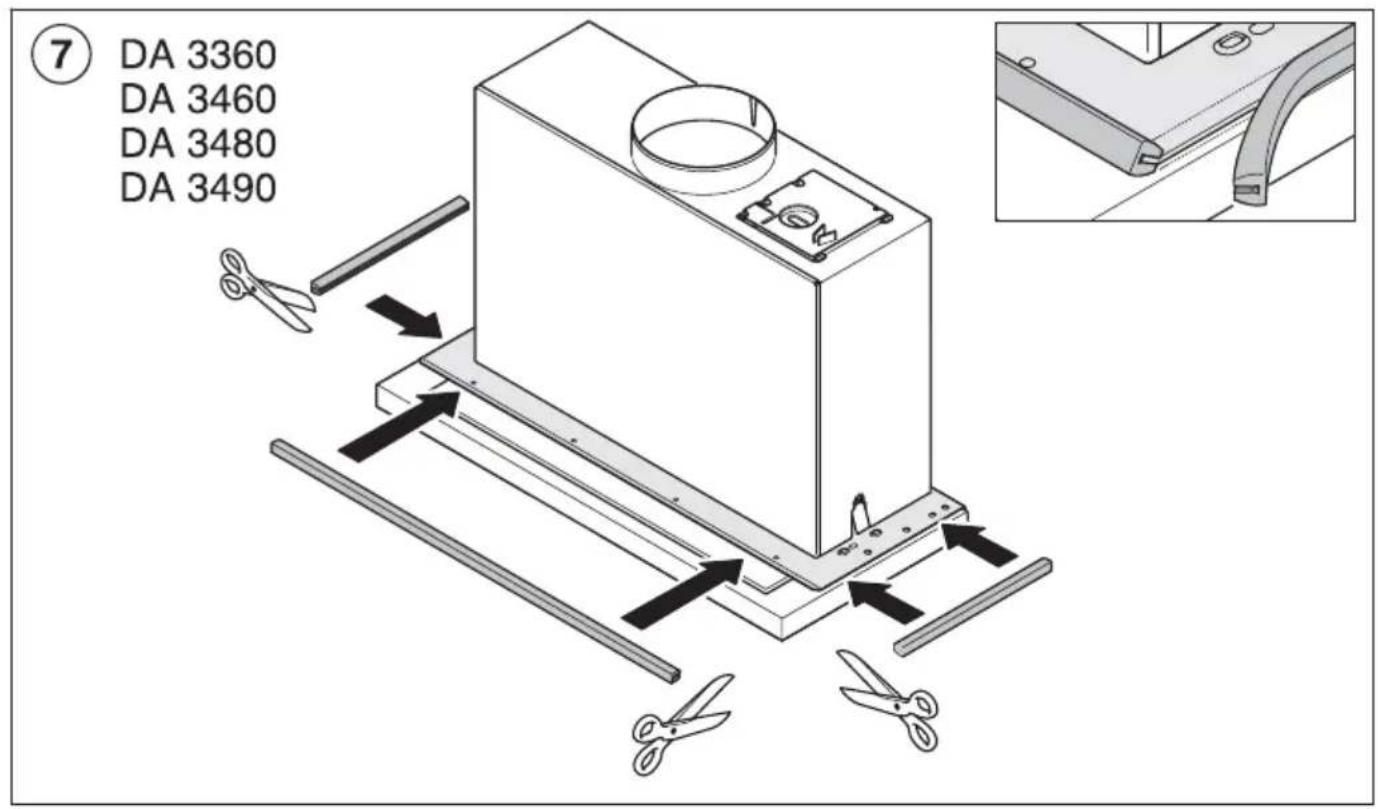
3) Trim the wall unit carcase so that it is 50 mm shorter than the wall unit door.
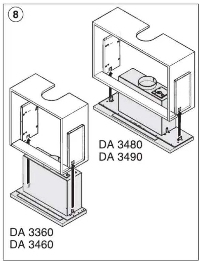
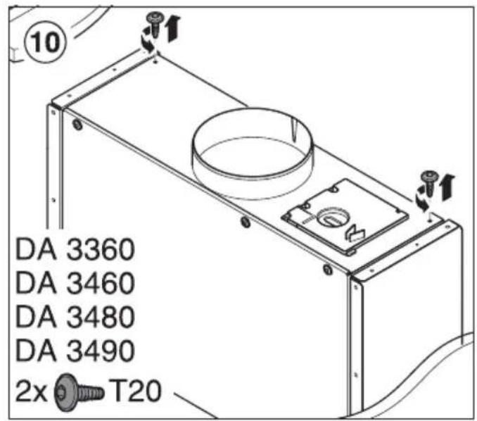
All other unit dimensions are as quoted on the building-in diagrams for DA 3360, 3460, 3480 and 3490. A unit base is not required.
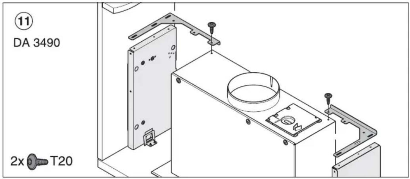
DA 3490 cannot be installed in a 600 mm wide unit with the drop-down frame.
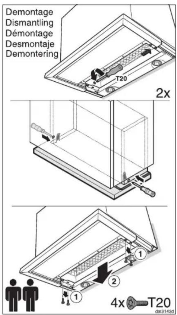
⚠ The safety distance between the cooker hood and the hob must be maintained when the cooker hood is lowered.
Ensure that the area underneath the cooker hood is free and that when the cooker hood is lowered, it will not be hindered by other objects (e.g. tiling, units to the side).
Please also check that the cooker hood can move freely up and down inside the furniture unit.
Do not attach any components to the cooker hood which could impede its movement.
⚠ The connection cable must be able to move freely with no risk of entrapment when the cooker hood moves.
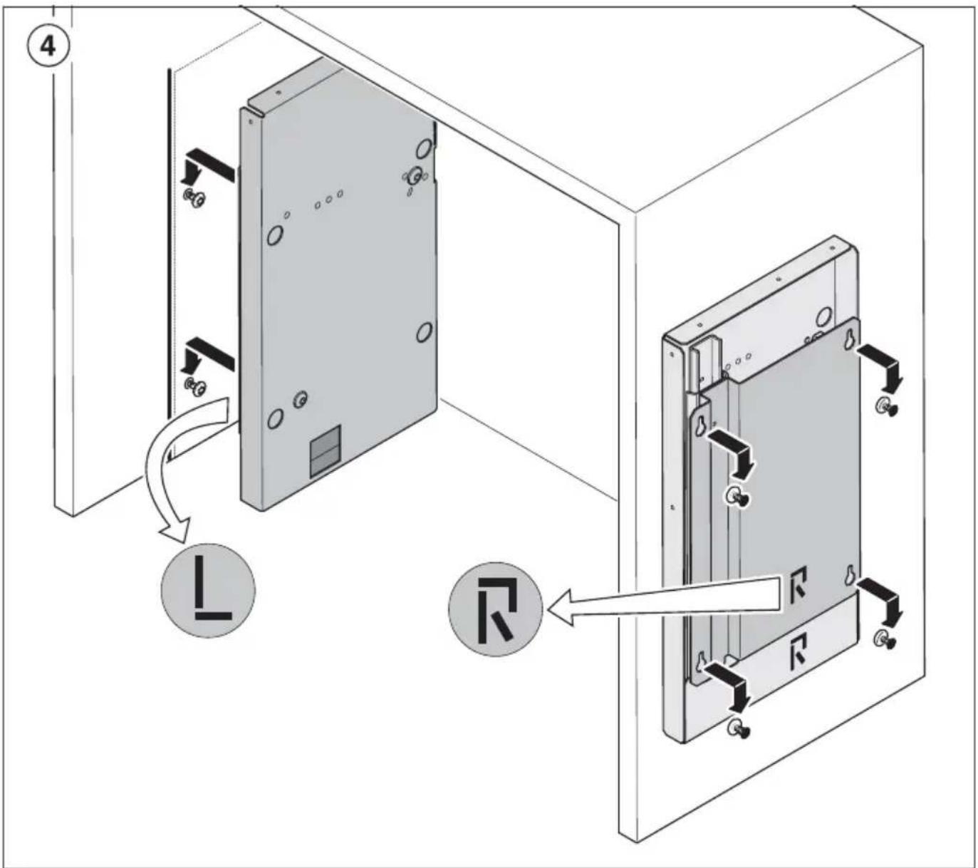
Installation
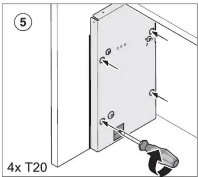
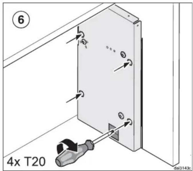
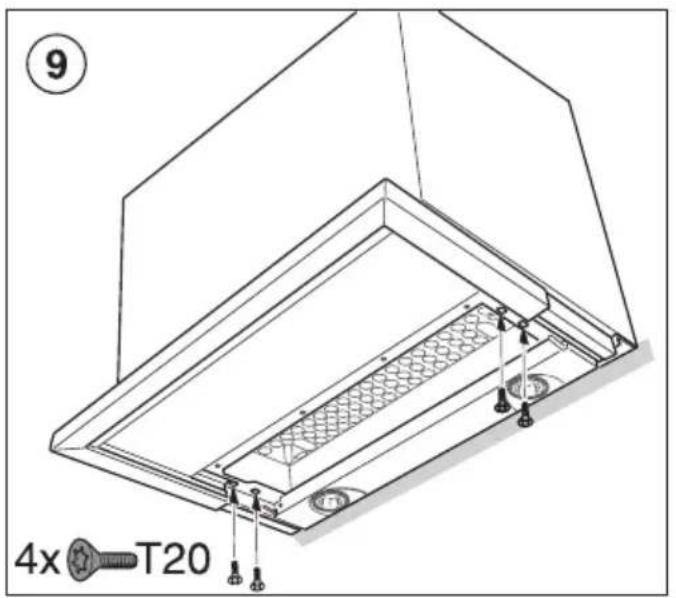
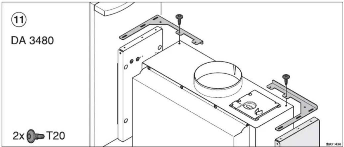
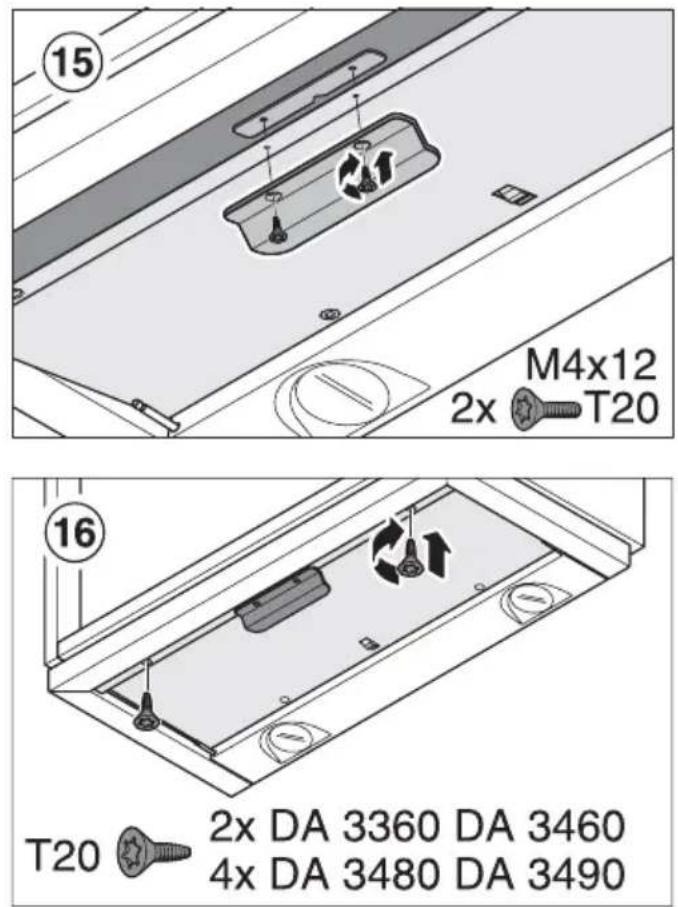
■ Please follow the installation steps on Page 26.
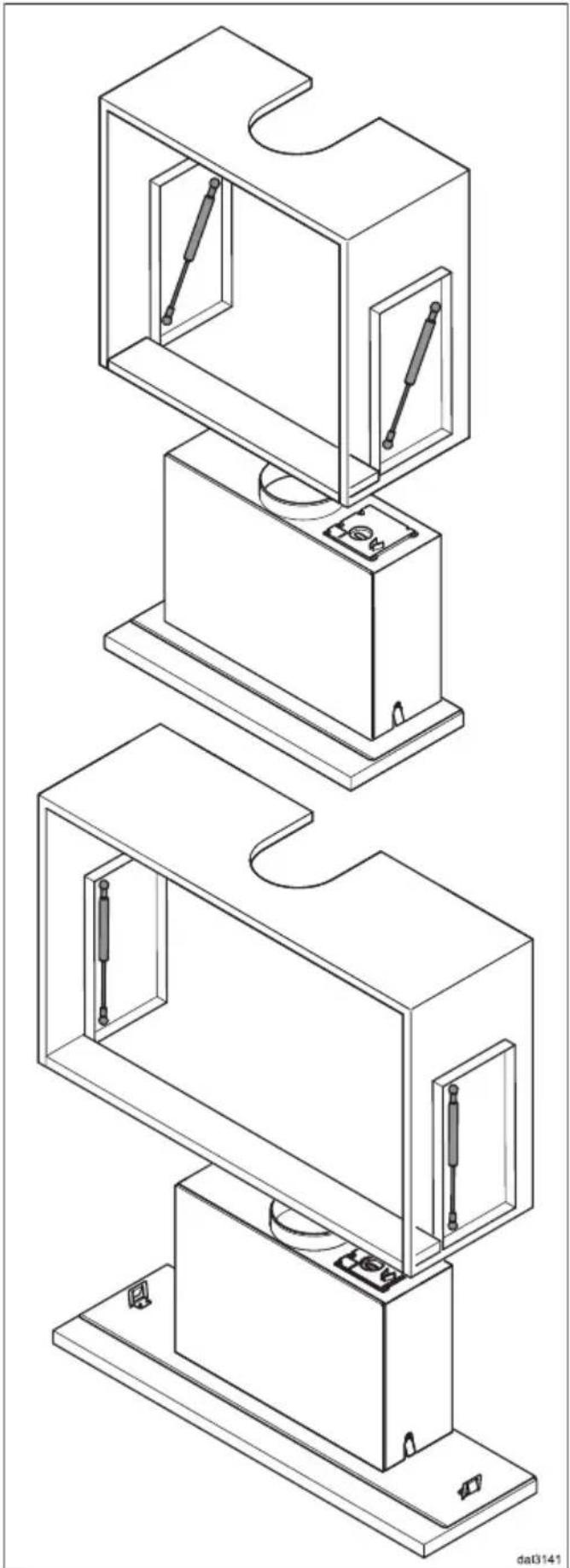
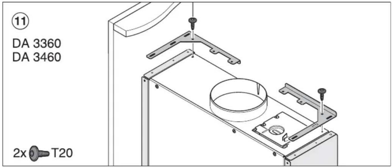
The cooker hood is raised and lowered by two gas-filled springs.
The position of the upper mounting of the gas-filled springs depends on the weight of the cooker hood. The weight of the cooker hood varies according to width and type.
The heavier the hood, the further forward the mounting needs to be positioned.
The correct position is important for problem-free up and down movement of the cooker hood.
■ To do this, before installation position the gas-filled springs as shown in the first steps.
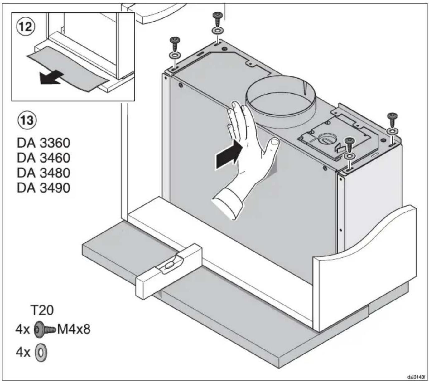
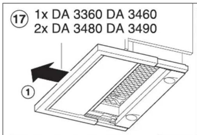
■ The cooker hood requires flexible ducting to allow it to drop down. Please use the highly flexible ducting hose supplied.
natural_image
Technical line drawing of a multi-tiered mechanical assembly with internal components and mounting base (no text or symbols)Operation
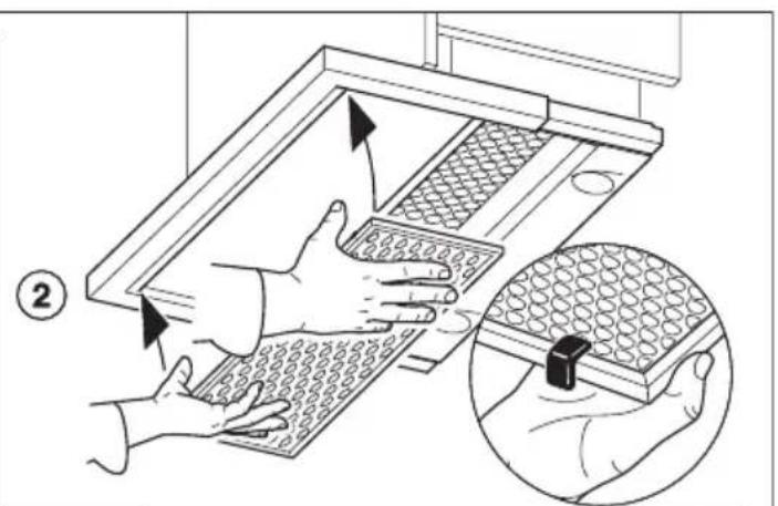
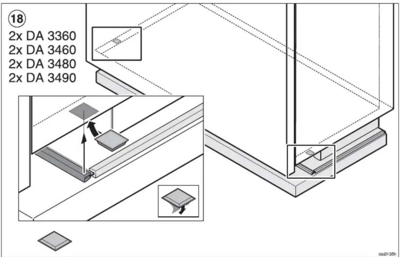
To avoid the deflector plate getting scratched by the furniture door, ensure that
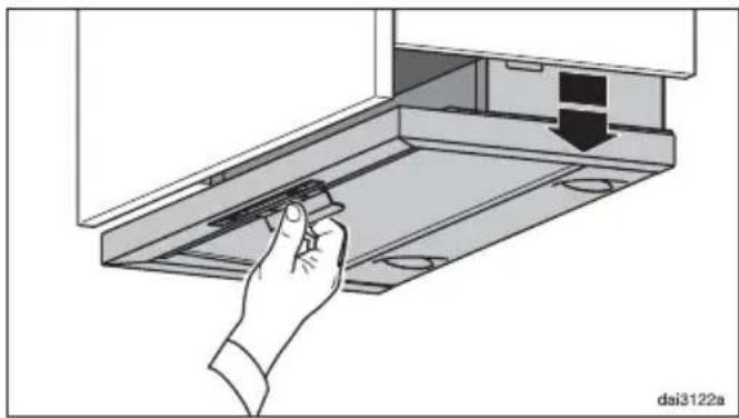
- before the deflector plate is pulled forward, the cooker hood is pulled down until it clicks,
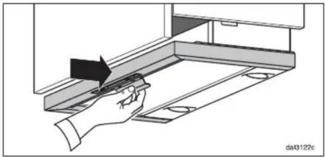
- before raising the cooker hood, the deflector plate is first pushed in as far as it will go.
natural_image
Hand inserting a component into a device rack, showing a black arrow indicating direction (no text or symbols present)■ Pull the cooker hood down by the handle, until it clicks.
natural_image
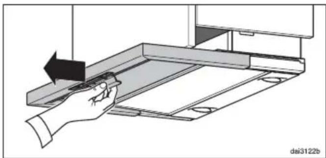
Illustration of a hand using a tool to adjust or install a mechanical component, with no visible text or symbols.■ Then pull the deflector plate out.
The cooker hood will switch itself on as described in the operating instructions.
natural_image
Illustration of a hand using a tool to adjust or install a mechanical component, with no visible text or symbols.■ After cooking push the deflector plate back in as far as it will go.
The cooker hood will switch itself off.
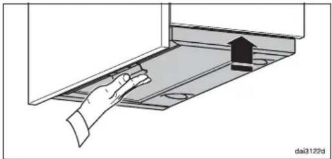
natural_image
Illustration of a hand interacting with a device panel, showing a black arrow pointing to a house on the screen (no text or symbols)■ Then push the cooker hood up by the handle as far as it will go.
natural_image
Technical line drawing of a multi-tiered mechanical assembly with internal components and mounting base (no text or symbols)Utilisation
natural_image
Hand inserting a component into a device panel (no text or symbols visible)natural_image
Illustration of a hand using a tool to adjust or install a mechanical component, with no visible text or symbols.natural_image
Illustration of a hand using a tool to adjust or install a component on a mechanical assembly (no text or symbols visible)natural_image
Illustration of a hand interacting with a metal shelf under an upward arrow (no text or symbols)natural_image
Technical line drawing of a multi-tiered mechanical assembly with internal components and mounting base (no text or symbols)Bediening
natural_image
Hand inserting a component into a device panel, showing a black arrow indicating direction (no text or symbols present)natural_image
Illustration of a hand using a tool to adjust or install a metal shelf panel (no text or symbols visible)natural_image
Illustration of a hand using a tool to adjust or install a component on a mechanical assembly (no text or symbols visible)natural_image
Illustration of a hand interacting with a mechanical component, showing a hand pressing a button on a tray (no text or symbols)natural_image
Technical line drawing of a multi-tiered mechanical assembly with internal components and mounting base (no text or symbols)Manejo
natural_image
Hand inserting a component into a device panel, showing a black arrow indicating direction (no text or symbols present)natural_image
Illustration of a hand using a tool to adjust or install a mechanical component, with no visible text or symbols.natural_image
Illustration of a hand using a tool to adjust or install a component on a mechanical assembly (no text or symbols visible)natural_image
Illustration of a hand interacting with a laptop screen, showing a black arrow pointing to the screen (no text or symbols present)natural_image
Technical line drawing of a multi-tiered mechanical assembly with internal components and mounting base (no text or symbols)Använda fläkten
natural_image
Hand inserting a component into a device rack, showing a black arrow indicating direction (no text or symbols present)natural_image
Illustration of a hand using a tool to adjust or install a mechanical component, with no visible text or symbols.natural_image
Illustration of a hand using a tool to adjust or install a component, with no visible text or symbols.natural_image
Illustration of a hand interacting with a laptop screen, showing a black arrow and square foot (no text or symbols)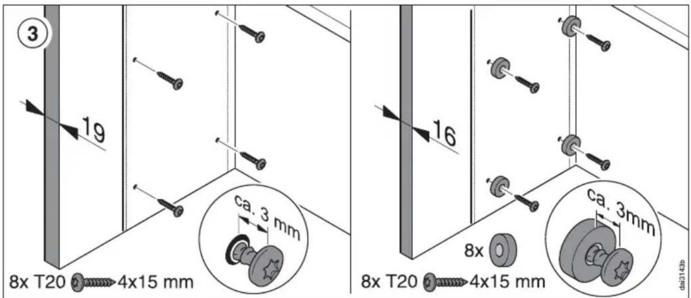
Montage - Installation - Montaje - Montering
Montage - Installation - Montaje - Montering
Montage - Installation - Montaje - Montering
Montage - Installation - Montaje - Montering
natural_image
Illustration of hands handling a grid-patterned device with an inset showing the same hand inserting a small object (no text or symbols present)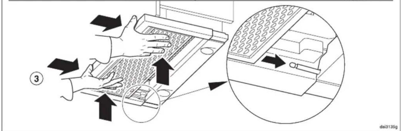
Germany:
Miele & Cie. KG

Brand : MIELE
Model : DAR 3000
Category : Range hood