SCC130BP - Soundbar SAMSUNG - Free user manual and instructions
Find the device manual for free SCC130BP SAMSUNG in PDF.

| Product Type | CCTV Surveillance Camera |
| Transmission System | PAL |
| CCD Sensor | 1/3" IT type Super-HAD CCD |
| Number of Pixels | 500 (H) x 582 (V) |
| Resolution | 330 TV lines |
| Signal-to-Noise Ratio | 50 dB (AGC OFF) |
| Minimum Illumination | 0.15 Lux (F1.2) |
| Video Output | Composite 1 Vp-p, 75 Ω, BNC connector |
| Power Supply | AC 24 V ±10% (50 Hz ±0.3 Hz) or DC 12 V (-5% to +10%) |
| Power Consumption | Approx. 3 Watts |
| Operating Temperature | -10°C to +50°C |
| Operating Humidity | Up to 90% |
| Dimensions (W x H x D) | 65 x 52 x 133 mm (BNC connector included) |
| Weight | Approx. 450 g |
| Main Functions | Backlight Compensation (BLC), Automatic Gain Control (AGC), Automatic White Balance (ATW/AWC), Electronic Shutter 1/60 to 1/120,000 s, Digital Line Lock |
| Maintenance and Cleaning | Clean with a soft dry cloth. Do not use harsh detergents or liquid products. |
| Safety | Do not expose to rain or moisture. Disconnect before cleaning. Have repairs carried out by qualified personnel. |
| Spare Parts and Repairability | Use only spare parts recommended by the manufacturer. Have safety checks performed after repairs. |
Frequently Asked Questions - SCC130BP SAMSUNG
User questions about SCC130BP SAMSUNG
0 question about this device. Answer the ones you know or ask your own.
Ask a new question about this device
Download the instructions for your Soundbar in PDF format for free! Find your manual SCC130BP - SAMSUNG and take your electronic device back in hand. On this page are published all the documents necessary for the use of your device. SCC130BP by SAMSUNG.
USER MANUAL SCC130BP SAMSUNG
text_image
E F G ES I RU J
CAUTION
RISK OF ELECTRIC SHOCK, DO NOT OPEN

CAUTION : TO REDUCE THE RISK OF ELECTRIC SHOCK, DO NOT REMOVE COVER (OR BACK). NO USER-SERVICEABLE PARTS INSIDE. REFER SERVICING TO QUALIFIED SERVICE PERSONNEL.
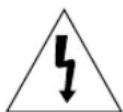
The lightning flash, with an arrowhead symbol, within an equilateral triangle, is intended to alert the user to the presence of uninsulated “dangerous voltage” within the product’s enclosure, that may be of sufficient magnitude to constitute a risk of electric shock to persons.

The exclamation point within an equilateral triangle is intended to alert the user to the presence of important operating and maintenance (servicing) instruction in the literature accompanying the appliance.
WARNING : TO PREVENT FIRE OR SHOCK HAZARD, DO NOT EXPOSE THIS APPLIANCE TO RAIN OR MOISTURE.
IMPORTANT SAFEGUARDS
- Read all of these instructions.
- Save these instruction for later use.
- Unplug this appliance system from the wall outlet before cleaning Do not use liquid cleaners or aerosol cleaner. Use a damp cloth for cleaning.
- Do not use attachments not recommended by the appliance manufacturer, as they may cause hazards.
- Do not use this appliance near water for example, near a bathtub, washbowl, kitchen sink, laundry tub, in a wet basement, or near a swimming pool, etc.
- Do not place this appliance on an unstable cart, stand, or table.
The appliance may fall causing serious injury to a child or adult, and serious damage to the appliance.
Use only with a cart or stand recommended by the manufacturer's instructions, and use a mounting kit approved by the manufacturer.
An appliance and cart combination should be moved with care. Quick stops, excessive force,
and uneven surfaces may cause the appliance and cart combination to overturn.

- Slots and openings in the cabinet on the back or bottom are provided for ventilation, to insure reliable operation of the appliance, and to protect from overheating.
These openings should never be blocked by placing the appliance on a bed, sofa, rug or other similar surfaces. This appliance should never be placed near or over a radiator or heat register. This appliance should not be placed in a built-in installation such as a bookcase, unless proper ventilation is provided. - This appliance should be operated only from the type of power source indicated on the marking label. If you are not sure of the type of power supplied to your home, consult your dealer or local power company.
- Do not allow anything to rest on the power cord. Do not locate this appliance where the cord will be abused by people walking on it.
- Do not overload wall outlets and extension cords, as this can result in fire or electric shock.
- Follow all warnings and instructions marked on the appliance.
-
Do not attempt to service this appliance yourself, as opening or removing covers may expose you to dangerous voltage or other hazards. Refer all servicing to qualified service personnel.
-
Unplug this appliance from the wall outlet and refer servicing to qualified service personnel under the following conditions:
a. When the power cord or plug is damaged or frayed.
b. If liquid has been spilled into the appliance.
c. If the appliance does not operate normally by following the operating instructions. Adjust only those controls that are covered by the operating instructions, as improper adjustment of other controls may result in damage and will often require extensive work by a qualified technician to restore the appliance to normal operation.
d. If the appliance has been exposed to rain or water.
e. If the appliance has been dropped or the cabinet has been damaged.
f. When the appliance exhibits a distinct change in performance this indicates a need for service.
- When replacement parts are required, be sure the service technician has used replacement parts specified by the manufacturer that have the same characteristics as the original part. Unauthorized substitutions may result in fire, electric shock, or other hazards.
- Upon completion of any service or repairs to the appliance, ask the service technician to perform routine safety checks to determine that the appliance is in safe operating condition.
Contents
- Introduction ...... 3
- Features 4
- Installation 5
Precautions in Installation and Use 5
Connecting Auto Iris Lens Connector 6
Mounting Lens 7
Setting Lens Selection Switch 8
Adjusting Back Focus 9
Connecting Cable 11
- Names and Functions of Parts 14
Names and Functions of Parts 14
Function Switches 16 - Product Specification 21
1. Introduction
Adopting the latest Super -HAD CCD, these cameras provide the best monitoring function when they are connected to CCTV system.
* In the mechanical fluorescent light environment, if you attach MANUAL IRIS and turn the ELC switch among FUNCTION switches on, color may be rolled.
In this case, supply AC power before you turn L/L switch among FUNCTION switches on. (NTSC:60HZ, PAL:50HZ)
* COLOR ROLLING is the problem that color on the monitor screen changes non-periodically. This happens when White Balance is not fixed, because a mechanical fluorescent light flickers when it's cycle is the same to the cycle of the power frequency.
2. Features
High Sensitivity
Adopting the 1/3" Super HAD CCD that has the latest built-in microchip lens, the high sensitivity is realized.
Excellent Back Light Compensation
Even when an intense light source or sunlight is in the back of your subject, a clear image will be provided due to the ideal combination of the excellent performance of the high light compression (KNEE Compensation) function and the BLC (Back Light Compensation) function.
Digital Line-lock
The control and reliability have been enhanced due to the Full Digital Line Lock, which allows users to adjust the Line Sync Phase.
Resolution
High resolution is realized due to the Full Digital Image Processing by the DSP for monitoring camera.
3. Installation
Precautions in Installation and Use
① Do not attempt to disassemble the camera yourself.
② Be cautious in handling the camera. Avoid striking or shaking the camera. Be cautious to avoid damage on the camera caused by improper storage or operation.
③ Do not expose this camera to rain or moisture. Do not operate this camera on a wet place.
④ Do not use strong or abrasive detergents when cleaning the camera body.
Use a dry cloth to clean the camera.
⑤ Keep the camera at a cool place away from the direct sunlight. Leaving it under the direct sunlight may result in the malfunction of the unit.

Connecting Auto Iris Lens Connector
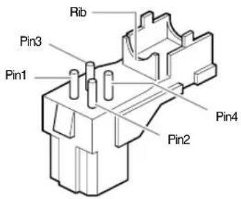
Prepare the following Auto Iris Lens Connector supplied with the camera.
text_image
Rib Pin3 Pin1 Pin2 Pin4Connect the cable of the control cable, whose covering is stripped, to the Auto Iris Lens Connector as shown below.
| Pin Number DC Control Type Video Control Type | ||
| 1 Damp(-) Power Source (+9V) | ||
| 2 Damp(+) Not used | ||
| 3 Drive(+) Video Signal | ||
| 4 | Drive(-) | GND |
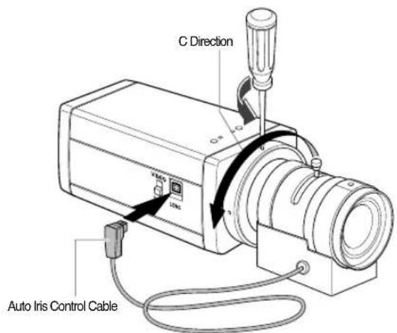
Mounting the Lens
Loosen a screw fixing the Flange Back Adjustment Ring by turning it counterclockwise and turn the Adjustment Ring to the "C" direction (counterclockwise) until it stops. Failure to do so may result in a damage caused by the bump of the lens against the image sensor part in the camera when mounting the lens.

text_image
C Direction USB Auto Iris Control CableSetting Lens Selection Switch
When lens mounting is completed, set the Lens selection Switch on the side of the camera according to the mounted lens type.
When the mounted lens is an Auto Iris Lens of the DC control type, set the Lens Selection Switch to "DC". When the mounted lens is an Auto Iris Lens of the Video control type, set the Lens Selection Switch to "VIDEO".
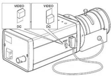
text_image
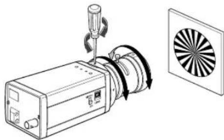
VIDEO DC VIDEO DCAdjusting Back Focus
Although the Back Focus of the camera has been adjusted in the factory before its shipment, the focus may not be accurate for a certain type of the lens. In this case, follow the procedures below to adjust the Back Focus. First, following is how to adjust the Back Focus of the Fixed Focus Lens.
① Lightly loosen the screw fixing the Back Focus Adjustment Ring using a screwdriver.
② Image a vivid subject (with check patterns) at a distance of more than 10m away and turn the Focus Ring to the infinity ( ) position.
③ Adjust the Back Focus Adjustment Ring to obtain the clearest image of the subject.
④ Fasten the screw fixing the Back Focus Adjustment Ring.
natural_image
Technical line drawing of a mechanical device with rotating components and a circular fan-like pattern (no text or symbols)
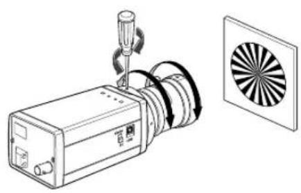
The following describes how to adjust the Back Focus when using a Zoom lens.
① Lightly loosen the screw fixing the Back Focus Adjustment Ring using a screwdriver.
② Image a vivid subject (with check patterns) at a distance of 3\~5m away and adjust the zoom of the lens to TELE as far as it goes. Then adjust the Focus Ring of the lens to obtain the clearest image of the subject.
③ Adjust the zoom of the lens to WIDE as far as it goes. Then turn the Back Focus Ring of the camera to obtain the clearest image of the subject.
④ Repeat no. ② & ③ 2\~3 times to exactly coincide the zoom focus from TELE and with that from WIDE.
⑤ Fasten the screw fixing the Back Focus Adjustment Ring.
natural_image
Technical line drawing of a mechanical device with a circular fan blade and screwdriver (no text or symbols)Note:
Turning the Back Focus Adjustment Ring to the "C" direction beyond the adjustable range makes a sound at the limit.
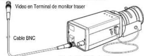
Connecting Cable
After mounting the lens and setting the Lens Selection Switch, connect the prepared cable to each terminal of the camera.
① First, connect one end of the BNC cable to the Video Output Terminal (VIDEO OUT) of the camera.
② Then connect the other end of the BNC cable to the Video Input Terminal of the monitor.
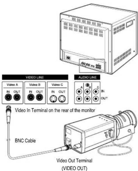
text_image
VIDEO LINE Video A IN OUT Video B IN OUT Video C IN OUT AUDIO LINE A B C IN OUT Video In Terminal on the rear of the monitor BNC Cable Video Out Terminal (VIDEO OUT)
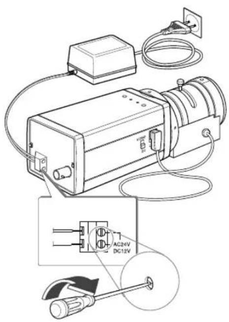
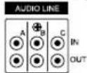
③ AC24V/DC12V Power Input Camera.
Connect 2 lines of the power adapter using a Phillips screwdriver to the Power IN Terminal of the camera as shown below.
※ Without the distinction of the polarity, connect to the AC 24V or AC 12V power source.
text_image
Technical diagram of an electrical device with labeled components including AC24V, DC12V, and power outlet connections.AC230V Power Input Camera
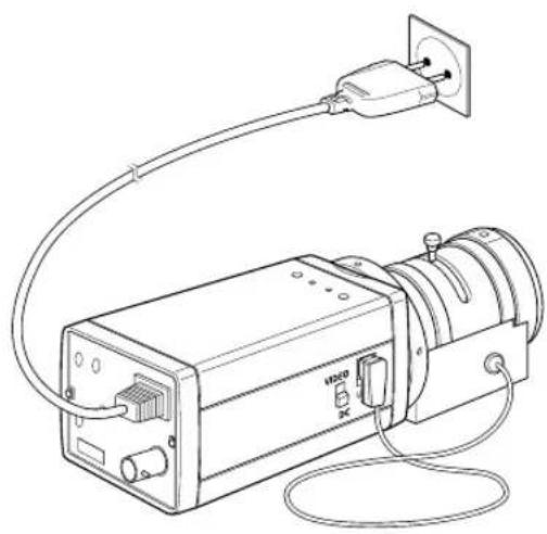
Connect the power input cord to the AC 230V power source.
natural_image
Line drawing of an electrical device with a power outlet, cable, and wiring (no text or symbols)4. Names and Functions of Parts Names and Functions of Parts
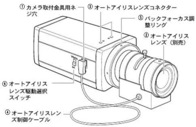
- Side View
text_image
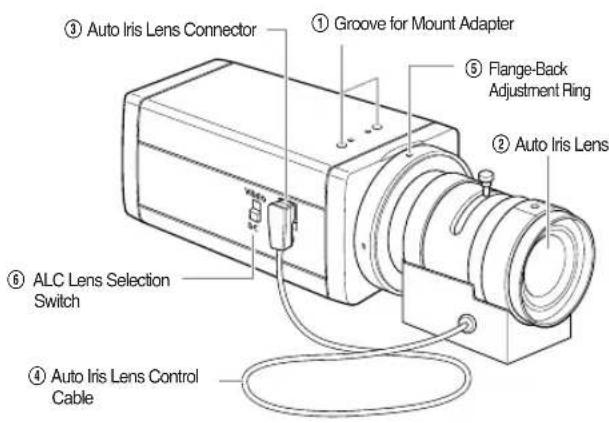
③ Auto Iris Lens Connector ① Groove for Mount Adapter ⑤ Flange-Back Adjustment Ring ② Auto Iris Lens ⑥ ALC Lens Selection Switch ④ Auto Iris Lens Control Cable① Groove for Mount Adapter
Use this groove for fixing the mount adapter to be connected to the bracket with screws to mount the camera on the bracket.
② Auto Iris Lens (Option)
Lens to be mounted on the camera
Note
When the surface of the camera lens is contaminated, wipe the surface gently with a tissue for lens or a cotton cloth applied with ethanol.
③ Auto Iris Lens Connector
Used for supplying power, which is required to control the iris of the lens, as well as control signal, video signal, or DC signal to the Auto Iris Control Lens.
④ Auto Iris Lens Control Cable
Used for transmitting the control signals to the camera to control the iris of the lens.
⑤ Flange-Back Adjustment Ring
Used for adjusting the Back Focus.
⑥ ALC Lens Selection Switch
Used when selecting the type of Auto Iris Lens to use. DC : Select this switch to DC when Iris Lens requiring DC control signal is mounted.
VIDEO : Select this switch to VIDEO when Auto Iris Lens requiring VIDEO control signal is mounted.

- Rear Panel
AC24V/DC12V Power Input Camera
text_image
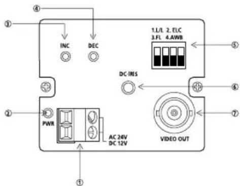
① ② ③ ④ INC DEC DC-IRIS AC 24V DC 12V ⑤ ⑥ ⑦ 1. L/L 2. ELC 3.FL 4.AWB VIDEO OUTAC230V Power Input Camera
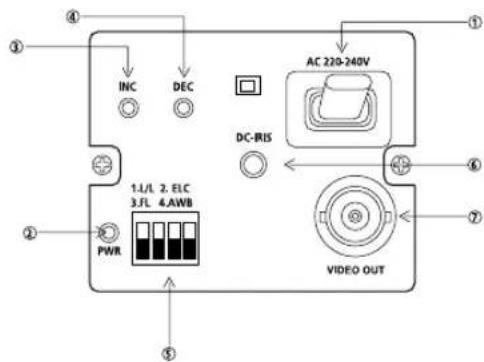
text_image
① ② ③ ④ INC DEC AC 220-240V DC-RIS 1.1/1 2. ELC 3.FL 4.AWB PWR VIDEO OUT① Power Connection Terminal
Terminal to be connected to the power (adapter) cable Connect it to AC 24V or DC 12V.
② Power Indication LED
While the power is properly supplied to the camera, the LED is turned on.
③, ④ INC/DEC Switch
The LINELOCK mode is useful for controlling Vertical Synchronous Phase.

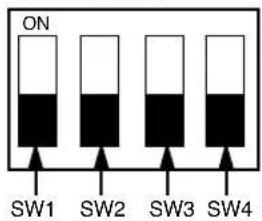
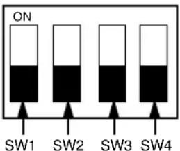
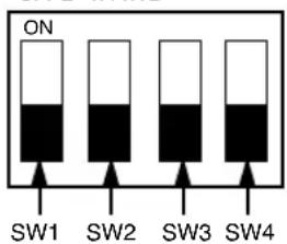
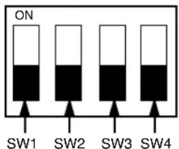
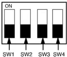
⑤ Function Switches
1) SW1 (LL):
When set to OFF, the camera operates in the Internal Sync mode. When set to ON, it operates in the Power Sync mode. If the camera is set to INT (Internal Sync) when monitoring in the Auto Switching mode with more than one camera connected to a sequential switcher, etc, the jump of the screen will occur each time of screen switching. To switch the screen gently without a jump, set the camera to LL and adjust the Vertical Sync Phase using the INC/DEC switch.
- L/L 2. ELC
- FL 4. AWB

text_image
ON SW1 SW2 SW3 SW42) SW2 (ELC):
Use this switch with the Manual Iris Lens. While this switch is ON, the speed of the electronic shutter varies with the brightness of the subject from 1/60 to 1/120,000 sec for automatically controlling the brightness of the screen. However, with the Auto Iris Lens (DC or Video Control), be sure to switch OFF. Color Rolling may occur in this mode. In that case, input AC power source to the camera and select SW1 "ON". (NTSC : 60HZ, PAL : 50HZ)
3) SW3 (FL):
This is to prevent flicker on the screen when NTSC system is used in 50HZ power supply region and PAL system is used in 60HZ power supply region. That is to prevent shaking on the screen resulted from the discordance of the vertical sync frequency and the flicker frequency of the illumination. While this switch is ON, the electronic shutter is fixed to 1/100sec (NTSC) or 1/120 sec (PAL).
4) SW4 (AWB):
When setting up ON, the color of screen is adjusted automatically in accordance with the change of lighting color temperature by the change of outer environment. (ATW) If the lighting condition is steady, OFF setting is available. The camera memorizes the lighting color temperature at the time when the switch setting is changed from ON to OFF, and the camera color is adjusted to the memorized color temperature. (AWC) If the lighting color temperature is changed and you want to make the camera be memorized/operated with the changed color temperature, re-operate the switch On/Off operation. However, be aware that an error may occur under the following conditions. First, a case that the subject is big, single color of the high chroma, and in the center of the screen or a case with almost no white color on the screen Second, a case with a specific illumination such as a natrium lamp
※ To adjust the Vertical Sync Phase using the INC/DEC switch in LL mode, the SW4 must be set to AWB "ON".
※ For DC 12V, the INT/LL mode is fixed to INT.
⑥ DC Iris Level Control
When the ALC Lens Selection Switch is set to DC, adjust this Iris Level Control using an adjustment rod such as a screwdriver.
⑦ Video Output Terminal
This is a terminal to be connected to the Input Terminal of the monitor. Through this terminal, the video signals are outputted.
5. Product Specifications
SCC-130B/131B
| Item Contents | |
| Product Type CCTV Camera | |
| Broadcasting NTSC STANDARD SYSTEM | |
| System | |
| CCD 1/3” IT type S-HAD CCD | |
| No. of Pixel 130B : 510(H) x 492(V) | |
| 131B : 768(H) x 494(V) | |
| Scanning Type 525 Line, 2:1 Interlace | |
| Frequency INTERNAL : 15,734 Hz(H) | |
| 59,94 Hz(V) | |
| LINE LOCK :15,750 Hz(H) | |
| 60 Hz(V) | |
| Sync Type INTERNAL | |
| LINE LOCK(When AC24V power source is used) | |
| Resolution 130B : 330TV Lines | |
| 131B: 520TV Lines | |
| S/N Ratio 50dB (AGC OFF) | |
| Min. Object 130B : 0.15 Lux (F1.2) | |
| Illumination 131B : 0.3 Lux (F1.2) | |

| ALC /ELC ALC | DC IRIS LENSVIDEO LENSELECElectronic SHUTTER IRIS function1/60 to 1/120,000 sec |
| Color Temperature ATW/AWC Mode | |
| BLC ON(Back Light Compensation) | |
| AGC ON | |
| Video Output COMPOSITE VIDEO OUT | |
| 1V p_p 75 Ω/BNC | |
| Power Source | AC24V ± 10%(60Hz ± 0.3Hz)DC12V -5% ~ +10% |
| Power Consumption | About 3 Watts |
| OperatingTemperature | -10°C~+50°C |
| OperatingHumidity | ~90% |
| Size 65(W) x 52(H) x 133(L)mm(BNC included) | |
| Weight | 450g |
SCC-100BP/101BP/130BP/131BP
| Item Contents | |
| Product Type CCTV Camera | |
| Broadcasting PAL STANDARD SYSTEM | |
| System | |
| CCD 1/3” IT type S-HAD CCD | |
| No. of Pixel 100BP/130BP : 500(H) x 582(V) | |
| 101BP/131BP : 752(H) x 582(V) | |
| Scanning Type 625 Line, 2:1 Interlace | |
| Frequency INTERNAL : 15,625 Hz(H) | |
| 50 Hz(V) | |
| LINE LOCK :15,625 Hz(H) | |
| 50 Hz(V) | |
| Sync Type INTERNAL | |
| LINE LOCK(When AC power source is used) | |
| Resolution 100BP/130BP : 330TV Lines | |
| 131BP/101BP: 520TV Lines | |
| S/N Ratio 50dB (AGC OFF) | |
| Min. Object 100BP/130BP : 0.15 Lux (F1.2) | |
| Illumination 131BP/101BP : 0.3 Lux (F1.2) | |

| ALC /ELC ALC | DC IRIS LENSVIDEO LENSELECElectronic SHUTTER IRIS function1/60 to 1/120,000 sec |
| Color Temperature | ATW/AWC Mode |
| BLC ON(Back Light Compensation) | |
| AGC ON | |
| Video Output | COMPOSITE VIDEO OUT1V p_p 75 Ω/BNC |
| Power Source | 100BP/101BPAC220V~240V(50Hz + 0.3Hz)130BP/131BPAC24V + 10%(50Hz + 0.3Hz)DC12V -5% ~ +10% |
| Power Consumption | 100BP/101BP: About 4 Watts130BP/131BP: About 3 Watts |
| Operating Temperature | -10°C~+50°C |
| Operating Humidity | ~90% |
| Size 65(W) x 52(H) | x 133(L)mm(BNC included) |
| Weight | 100BP/101BP : About 550g130BP/131BP : About 450g |

AVERTISSEMENT
RISQUE DE CHOC ELECTRIQUE, NE PAS OUVRIR

AVERTISSEMENT : AFIN DE RÉDUIRE LE RISQUE DE CHOC ELECTRIQUE, NE RETIREZ PAS LE COUVERCLE (OU L'ARRIÈRE). AUCUNE PIÈCE RÉPARABLE PAR L'UTILISATEUR À L'INTÉRIEUR. CONFIEZ LA RÉPARATION À UN PERSONNEL QUALIFIÉ.
natural_image
Technical line drawing of a mechanical device with rotating components and a circular fan pattern (no text or symbols)
natural_image
Technical line drawing of a mechanical device with a circular fan inset (no text or symbols)Remarque :
text_image
Technical diagram of an electrical device with labeled components including AC24V and DC12V connectionsnatural_image
Line drawing of a mechanical device with wiring and plug, no text or symbols present
③, ④ Boutons INC/DEC
- L/L 2. ELC
- FL 4. AWB
text_image
ON SW1 SW2 SW3 SW42) SW2 (ELC):
natural_image
Technical line drawing of a mechanical device with rotating components and a circular fan pattern (no text or symbols)
natural_image
Technical line drawing of a mechanical device with a circular fan blade and screwdriver, next to a separate panel (no text or symbols)Hinweis:
text_image
Technical diagram of an electrical device with labeled components and wiring connectionsBenutzerhandbuch
natural_image
Line drawing of an electrical device with a power outlet and cable, no text or symbols present
- L/L 2. ELC
- FL 4. AWB
text_image
ON SW1 SW2 SW3 SW42) SW2 (ELC):
natural_image
Technical line drawing of a mechanical device with rotating components and a circular fan pattern (no text or symbols)
natural_image
Technical line drawing of a device with a fan blade and mechanical components, no text or symbols present.Nota:
natural_image
Line drawing of a server unit with ventilation grilles and control buttons (no text or symbols)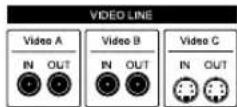
text_image
Video en Terminal de monitor traser Cable BNCtext_image
Technical diagram of an electrical device with labeled components including AC24V and DC12V connectionsnatural_image
Line drawing of a portable electronic device connected to a power outlet, with cables and connectors (no text or symbols)-
L/L 2. ELC
-
FL 4. AWB
text_image
ON SW1 SW2 SW3 SW4natural_image
Technical line drawing of a mechanical device with rotating components and a circular fan pattern (no text or symbols)natural_image
Technical illustration of a mechanical device with a screwdriver and rotating fan (no text or symbols)Nota:
text_image
Technical diagram of an electrical device with labeled components including AC24V and DC12V connectionsnatural_image
Line drawing of a vintage electronic device with cable, power outlet, and wiring (no text or symbols)
-
L/L 2. ELC
-
FL 4. AWB
text_image
ON SW1 SW2 SW3 SW42) SW2 (ELC):
natural_image
Diagram of a projector with rotating fan and blade, showing mechanical components and airflow direction (no text or symbols)
natural_image
Technical line drawing of a mechanical device with a circular fan blade and a cylindrical component (no text or symbols)Примечание:
text_image
Technical diagram of an electrical device with labeled components including AC24V, DC12V, and power outlet connections.natural_image
Line drawing of a portable electronic device connected to a power outlet, with cables and connectors (no text or symbols)
natural_image
Diagram of a mechanical device with rotating components and a circular patterned panel (no text or symbols)natural_image
Technical line drawing of a mechanical device with rotating components and a circular fan pattern (no text or symbols)ご参考
text_image
Technical diagram of an electrical device with labeled components including AC24V and DC12V connectionsnatural_image
Line drawing of an electrical device with a power outlet connected to a cable, no text or symbols present
4. 各部の名称と機能
カメラの部品名称と機能
・カメラ側面
-
L/L 2. ELC
-
FL 4. AWB