POF 1200 A1 - Milling machine PARKSIDE - Free user manual and instructions
Find the device manual for free POF 1200 A1 PARKSIDE in PDF.

| Product type | Router (plunge router) |
| Brand | Parkside |
| Model | POF 1200 A1 |
| Rated power | 1200 W |
| Rated voltage | 230 V~, 50 Hz |
| No-load speed | 11000 - 30000 min⁻¹ |
| Maximum plunge depth | 55 mm |
| Tool holder (collet) | 6 mm and 8 mm |
| Protection class | II (double insulation) |
| Sound pressure level (LpA) | 84.7 dB(A) |
| Sound power level (LwA) | 95.7 dB(A) |
| Hand-arm vibration (ah) | 6.437 m/s² |
| Speed preselection | Yes, 7 positions |
| Dust extraction connection | Yes, with adapter and reducer |
| Parallel guide included | Yes |
| Copy ring included | Yes |
| Router bit set included | 12 pieces |
| Maintenance and cleaning | Clean with a dry cloth; unplug before any maintenance |
| Warranty | 3 years |
| After-sales service France | 0800 919270 (toll-free) |
| Article number (IAN) | 100129 |
Frequently Asked Questions - POF 1200 A1 PARKSIDE
User questions about POF 1200 A1 PARKSIDE
0 question about this device. Answer the ones you know or ask your own.
Ask a new question about this device
Download the instructions for your Milling machine in PDF format for free! Find your manual POF 1200 A1 - PARKSIDE and take your electronic device back in hand. On this page are published all the documents necessary for the use of your device. POF 1200 A1 by PARKSIDE.
USER MANUAL POF 1200 A1 PARKSIDE
text_image
PDF online www.lidl-service.com PARKSIDE PDF 2013DÉFONCEUSE POF 1200 A1
FR
DÉFONCEUSE
Operation and Safety Notes
Translation of original operation manual
IAN100129
FR
Before reading, unfold both pages containing illustrations and familiarise yourself with all functions of the device.
GB Operation and Safety Notes Page 25
text_image
A 15 14 13 12 11 10 9 8 7 2 3 4 5 6 PARKSIDE POF 10W-A1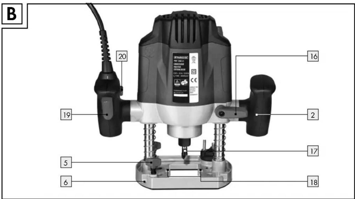
text_image
B 20 16 19 2 17 5 6 18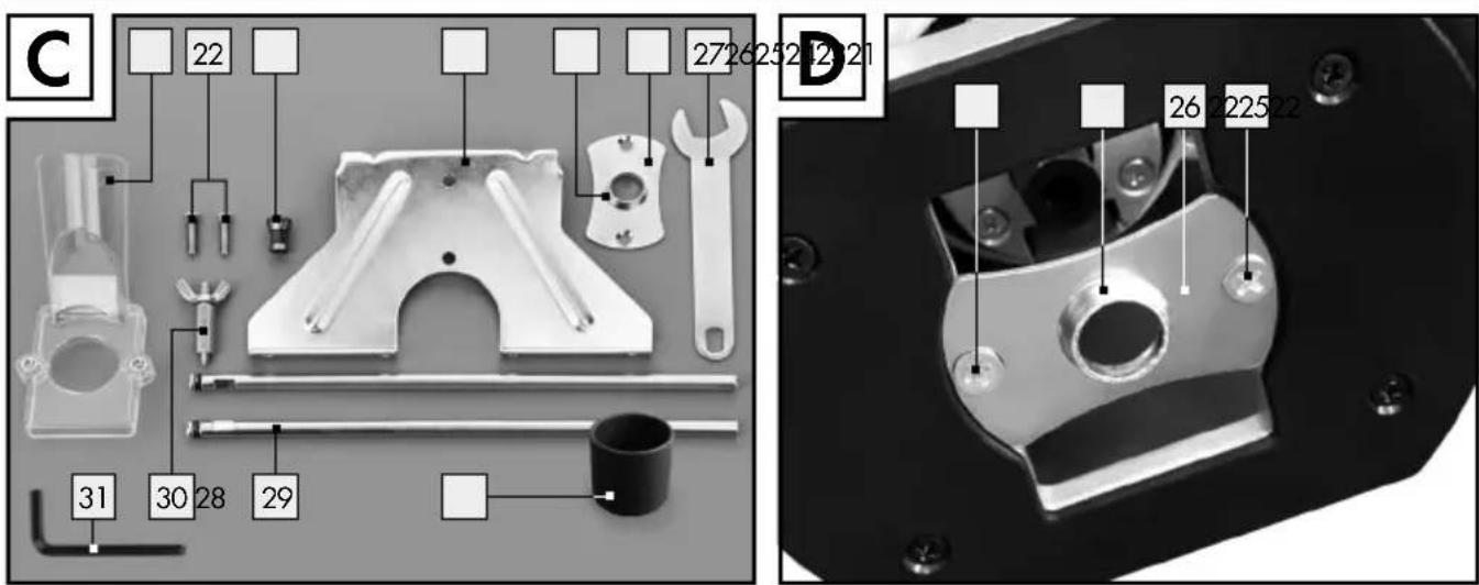
text_image
C 22 272625242321 31 30 28 29 D 26 2252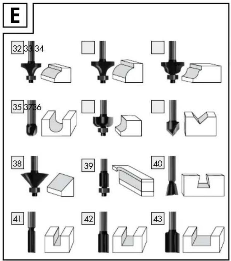
text_image
E 32 33 34 35 37 36 38 39 40 41 42 43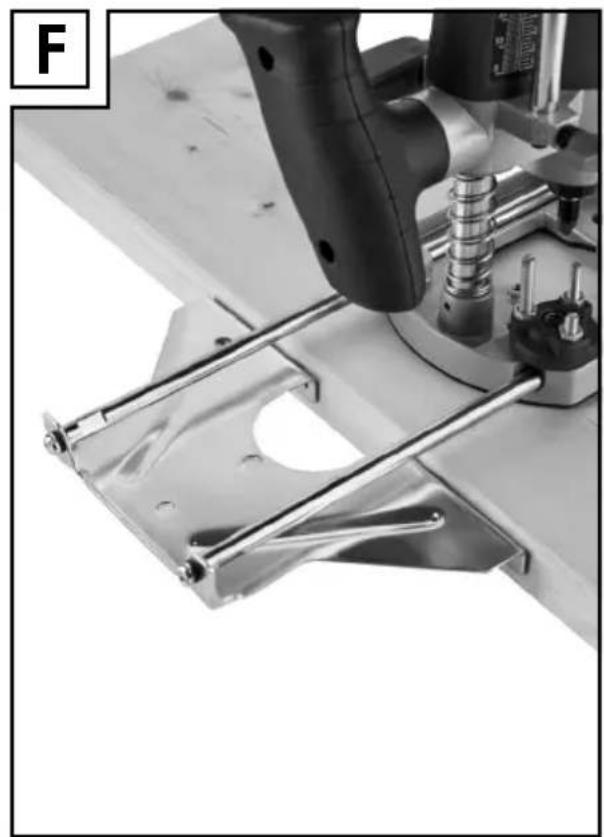
natural_image
Close-up of a mechanical assembly with metal components and a tool, no visible text or symbols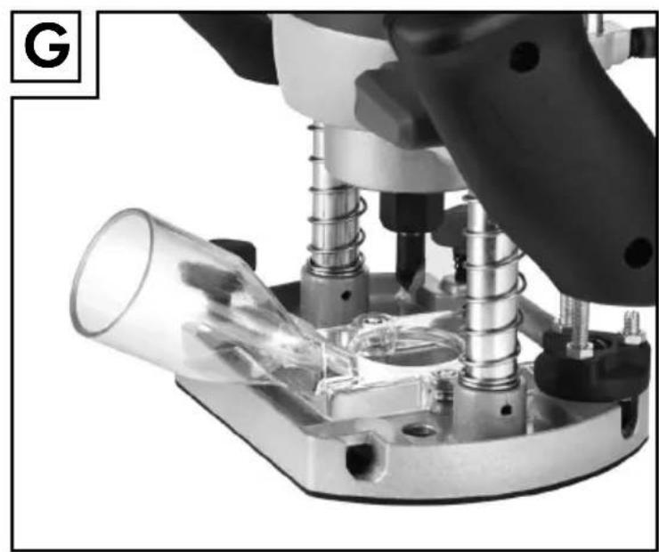
natural_image
Close-up of a mechanical assembly with glass components and metallic tubing (no visible text or symbols)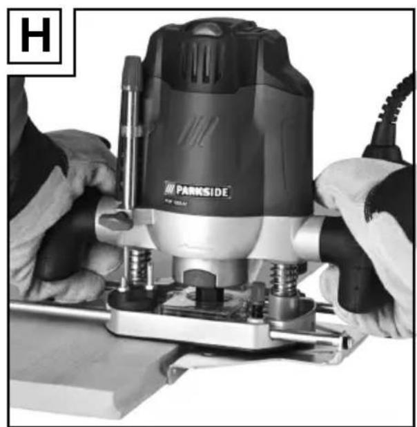
natural_image
Close-up of hands operating a Parkside electric drill press machine (no visible text or symbols)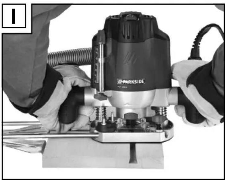
natural_image
Person operating a parkside power tool with visible circuit lines and fittings (no text or symbols)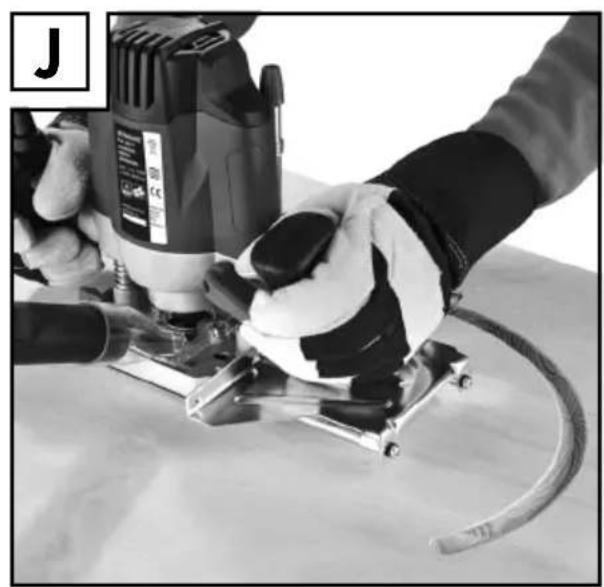
natural_image
Person using a power tool on a workbench, no visible text or symbolsIntroduction
Accessoires illustration C
natural_image
Diagram showing two curved arrows with directional arrows, one leftward and one rightward, over a shaded horizontal area (no text or symbols)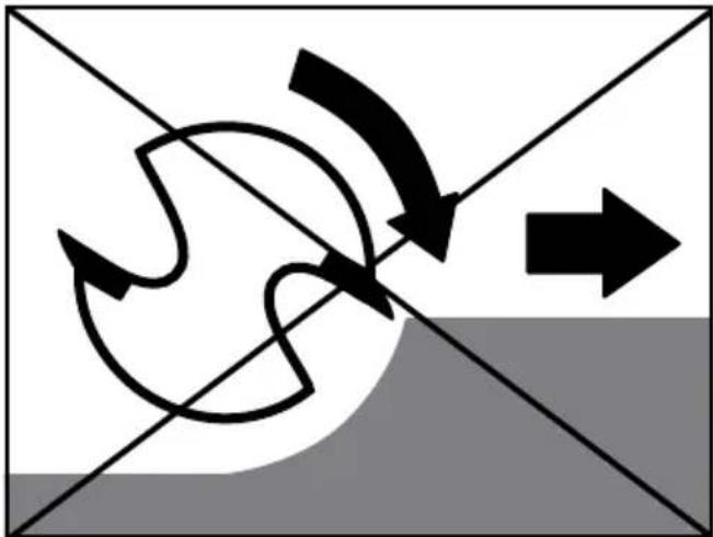
natural_image
Abstract diagram with curved arrows and a right-pointing arrow, no text or symbols present- Processus de fraisage
Directive Machines (2006/42/EC)
Directive CE Basse tension (2006/95/EC)
RoHS Directive (2011/65/EU)
natural_image
Diagram showing two curved arrows with directional arrows, one leftward and one curved, against a gray background (no text or symbols)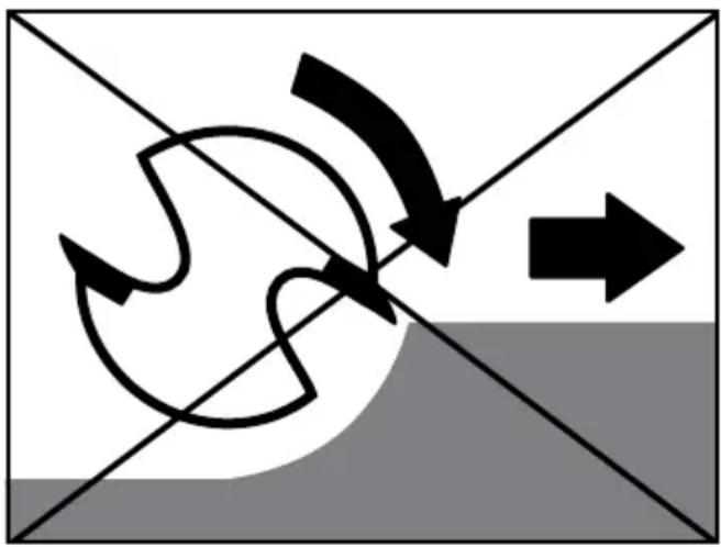
natural_image
Abstract diagram with curved arrows and a right-pointing arrow, no text or symbols presentFräsvorgang
Intended use......Page 26
Features Page 26
Scope of delivery Page 26
Technical Data Page 27
General power tool safety warnings
-
Work area safety Page 27
-
Electrical safety Page 27
-
Personal safety Page 28
-
Power tool use and care....Page 28
-
Service Page 29
Safety notices specific to routers......Page 29
Supplementary Instructions......Page 29
Original accessories/tools Page 29
Start-up
Router set/Applications Page 29
Using the router tool....Page 30
Attaching the extractor adapter....Page 30
Reducer......Page 30
Changing the collet Page 30
Fitting the guide fence....Page 30
Operation
Switching on and off Page 30
Presetting the speed....Page 30
Set the milling depth....Page 30
Readjust the milling depth....Page 31
Set the milling depth with the step stop Page 31
Milling direction......Page 31
Milling process....Page 31
Set the copy casing....Page 31
Milling with the copy casing......Page 32
Milling with a rip fence Page 32
Milling with a circular compass....Page 32
Maintenance and Cleaning......Page 32
Warranty Page 32
Translation of the original declaration of conformity /
Manufacturer Page 33
Router POF 1200 A1
●Introduction
We congratulate you on the purchase of your new device. You have chosen a high quality product. The instructions for use are part of the product. They contain important information concerning safety, use and disposal. Before using the product, please familiarise yourself with all of the safety information and instructions for use. Only use the unit as described and for the specified applications. If you pass the product on to anyone else, please ensure that you also pass on all the documentation with it.
Intendeduse
This device is intended to mill grooves, edges, profiles and slots on a wooden, plastic or light surface, as well as copy milling. This device is not intended for outdoor use. Any other uses, and / or modifications to the appliance, are deemed to be improper usage and may result in serious physical injury. Not for commercial applications.
Features
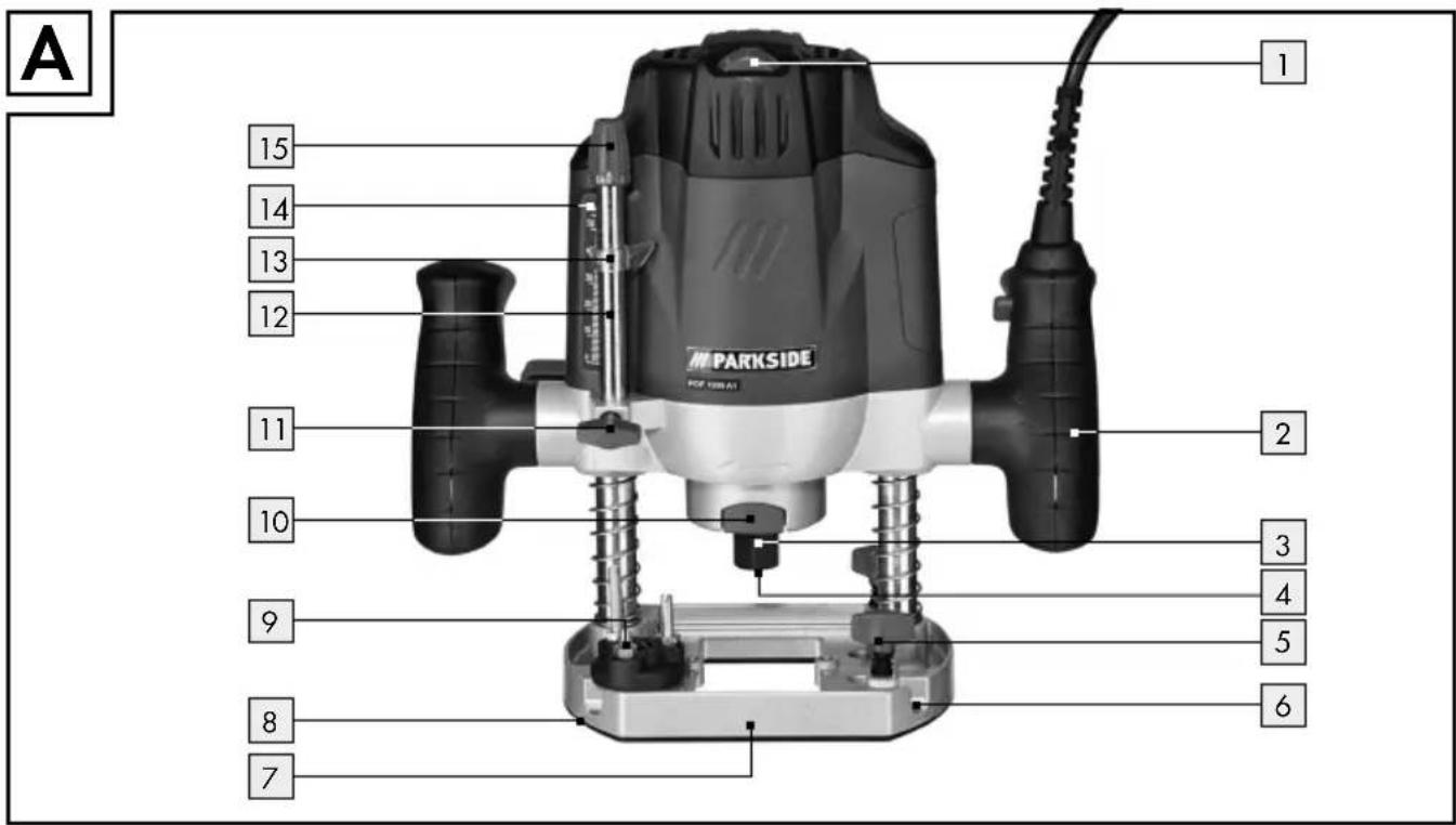
Front view figure A
| 1 | Speed setting |
| 2 | Handle |
| 3 | Union nut |
| 4 | Collet 8 mm (preinstalled in union nut 3) |
| 5 | Locking screw |
| 6 | Guide rail |
| 7 | Base plate |
| 8 | Sliding plate |
| 9 | Step stop |
| 10 | Spindle-lock key |
| 11 | Lock screw |
| 12 | Depth stop |
| 13 | Index indicator |
| 14 | Dial milling depth adjustment |
| 15 | Control dial (milling depth-fine adjustment) |
Back view figure B
| 16 | Clamping lever |
| 17 | Router tool |
| 18 | Drilling extractor adapter |
| 19 | ON/OFF switch |
| 20 | Start lockout |
Parts figure C
| 21 | Extractor |
| 22 | Screw |
| 23 | Collet 6 mm |
| 24 | Rip fence |
| 25 | Thrust ring |
| 26 | Copy casing |
| 27 | Open-ended spanner with slot |
| 28 | Reducer |
| 29 | Sliding bar with screw for rip fence24 |
| 30 | Centring pin |
| 31 | Socket head wrench |
Router set figure E
| 32 | Round and profile cutter 22 mm/R 6.3 mm |
| 33 | Round and profile cutter 28.6 mm/R 9.5 mm |
| 34 | Round and profile cutter 25 mm/R 4 mm |
| 35 | Hollow cutter 12.7 mm/R 6.3 mm |
| 36 | Hollow cutter 22 mm/R 6.3 mm |
| 37 | V-groove cutter 12.7 mm/Angle 90° |
| 38 | Bevel cutter 32 mm/Angle 45° |
| 39 | Flush cutter 12.7 mm |
| 40 | Dovetail cutter 12.7 mm/Angle 14° |
| 41 | Slot cutter 6 mm |
| 42 | Slot cutter 12 mm |
| 43 | Slot cutter 16 mm |
- Scope of delivery
1 Router
1 Open-ended spanner with slot
1 Collet 6 mm
1 Collet 8 mm (installed)
1 Extractor
1 Rip fence with 2 guides
1 Copy casing with 2 screws
1 Centring pin
1 Milling set 12 parts
1 Reducer
1 Socket head wrench
1 Set of operating instructions
●TechnicalData
Rated power input: 1200 W
Rated voltage: 230 V\~, 50 Hz
Idle speed: n 11000-30000 min ^-1
Plunge depth: 55 mm
Tool holder: 6/8 mm
Protection class: II/
Noise and vibration data:
Measured sound value determined according to EN 60745. The A-rated noise levels of the electrical power tool are typically at:
Sound pressure level: 84.7 dB(A)
Sound power level: 95.7 dB(A)
Uncertainty K: 3 dB
Wear hearing protection!
Evaluated acceleration, typically:
Hand / arm vibration a_h = 6.437 m/s^2
Instability K = 1.5 m/s ^4
WARNING! The vibration level specified in these instructions was measured in accordance with an EN 60745 standardised measurement process and can be used to compare equipment. The vibration emission value specified can also serve as a preliminary assessment of the exposure.
The vibration level will change according to the application of the electrical tool an in some cases may exceed the value specified in these instructions. Regularly using the electric tool in such a way may make it easy to underestimate the vibration.
Note: If you wish to make an accurate assessment of the vibration loads experienced during a particular period of working, you should also take into account the intervening periods of time when the device is switched off or is running but is not actually in use. This can result in a much lower vibration load over the whole of the period of working.
● General power tool safety warnings

WARNING! Read all safety warnings and all instructions.
Failure to follow the warnings and instructions may result in electric shock, fire and / or serious injury.
Save all warnings and instructions for future reference.
The term "power tool" in the warnings refers to your mains-operated (corded) power tool or battery-operated (cordless) power tool.
1. Work area safety
a) Keep work area clean and well lit.
Cluttered or dark areas invite accidents.
b) Do not operate power tools in explosive atmospheres, such as in the presence of flammable liquids, gases or dust.
Power tools create sparks which may ignite the dust or fumes.
c) Keep children and bystanders away while operating a power tool. Distractions can cause you to lose control.
2. Electrical safety
a) Power tool plugs must match the outlet. Never modify the plug in any way. Do not use any adapter plugs with earthed (grounded) power tools. Unmodified plugs and matching outlets will reduce risk of electric shock.
b) Avoid body contact with earthed or grounded surfaces, such as pipes, radiators, ranges and refrigerators.
There is an increased risk of electric shock if your body is earthed or grounded.
c) Do not expose power tools to rain or wet conditions. Water entering a power tool will increase the risk of electric shock.
3. Personal safety
d) Do not abuse the cord. Never use the cord for carrying, pulling or unplugging the power tool. Keep cord away from heat, oil, sharp edges or moving parts. Damaged or entangled cords increase the risk of electric shock.
e) When operating a power tool outdoors, use an extension cord suitable for outdoor use. Use of a cord suitable for outdoor use reduces the risk of electric shock.
f) If operating a power tool in a damp location is unavoidable, use a residual current device (RCD) protected supply. Use of an RCD reduces the risk of electric shock.
a) Stay alert, watch what you are doing and use common sense when operating a power tool. Do not use a power tool while you are tired or under the influence of drugs, alcohol or medication. A moment of inattention while operating power tools may result in serious personal injury.
b) Use personal protective equipment. Always wear eye protection. Protective equipment such as dust mask, non-skid safety shoes, hard hat, or hearing protection used for appropriate conditions will reduce personal injuries.
c) Prevent unintentional starting. Ensure the switch is in the off-position before connecting to power source and / or battery pack, picking up or carrying the tool. Carrying power tools with your finger on the switch or energising power tools that have the switch on invites accidents.
d) Remove any adjusting key or wrench before turning the power tool on. A wrench or a key left attached to a rotating part of the power tool may result in personal injury.
e) Do not overreach. Keep proper footing and balance at all times. This enables better control of the power tool in unexpected situations.
f) Dress properly. Do not wear loose clothing or jewellery. Keep your hair,
clothing and gloves away from moving parts. Loose clothes, jewellery or long hair can be caught in moving parts.
g) If devices are provided for the connection of dust extraction and collection facilities, ensure these are connected and properly used. Use of dust collection can reduce dust-related hazards.
4. Power tool use and care
a) Do not force the power tool. Use the correct power tool for your application.
The correct power tool will do the job better and safer at the rate for which it was designed.
b) Do not use the power tool if the switch does not turn it on and off. Any power tool that cannot be controlled with the switch is dangerous and must be repaired.
c) Disconnect the plug from the power source and / or the battery pack from the power tool before making any adjustments, changing accessories, or storing power tools. Such preventive safety measures reduce the risk of starting the power tool accidentally.
d) Store idle power tools out of the reach of children and do not allow persons unfamiliar with the power tool or these instructions to operate the power tool. Power tools are dangerous in the hands of untrained users.
e) Maintain power tools. Check for misalignment or binding of moving parts, breakage of parts and any other condition that may affect the power tool's operation. If damaged, have the power tool repaired before use. Many accidents are caused by poorly maintained power tools.
f) Keep cutting tools sharp and clean.
Properly maintained cutting tools with sharp cutting edges are less likely to bind and are easier to control.
g) Use the power tool, accessories and tool bits etc. in accordance with these instructions, taking into account the working conditions and the work to
be performed. Use of the power tool for operations different from those intended could result in a hazardous situation.
5. Service
a) Have your power tool serviced by a qualified repair person using only identical replacement parts. This will ensure that the safety of the power tool is maintained.
● Safety notices specific to routers
Only hold the power tool by the insulated handle areas as the router may touch the tool's mains cable. Contact with a live wire could cause metal parts of the device to become live and lead to electric shock.
Fix and secure the work piece to a stable surface using clamps or other means. When only securing the work piece by hand or against your body it will remain unstable, which could lead to loss of control.
■ Wear a dust mask.
SupplementaryInstructions
The permissible rotational speed of the router tool must be at least as high as the maximum speed indicated on the electrical power tool. Parts used at higher than permissible speeds may be ruined.
The router or other parts must fit precisely in the collet (shaft diameter 6/8) of your electric power tool. Cutting tools which do not fit precisely in the collet of the electric power tool turn unevenly, vibrate strongly and can lead to a loss of control.
Always switch on the electrical power tool before placing it against the work-piece. There is also the risk of kickback if the electric power tool becomes caught in the work-piece.
- Keep your hands away from the cutting area and the router. Keep your
second hand on the additional handle or on the engine housing. If you hold the router with both hands, they cannot be injured by the router.
■ Never use on metal objects, nails or screws. The router can become damaged and this may lead to higher vibrations.
Use suitable detectors in order to look for hidden supply lines, or consult your local power authority. Contact with electric lines can lead to fire and electric shocks. Damage to a gas line can lead to explosions. Breaking a water line can cause damages.
• Original accessories/tools
■ solely the accessories and attachments detailed in the operating instructions, or those which are compatible with the device.
- Start-up
- Router set/Applications
Original attachment included in delivery:
To profile:
32 Round and profile cutter 22 mm/R 6.3 mm
33 Round and profile cutter 28.6 mm/R 9.5 mm
34 Round and profile cutter 25 mm/R 4 mm
35 Hollow cutter 12.7 mm/R 6.3 mm
36 Hollow cutter ∅ 22 mm/R 6.3 mm
37 V-groove cutter 12.7 mm/Angle 90°
38 Bevel cutter 32 mm/Angle 45°
39 Flush cutter ∅ 12.7 mm
To connect:
40 Dovetail cutter 12.7 mm/Angle 14°
41 Slot cutter 6 mm
42 Slot cutter ∅ 12 mm
43 Slot cutter ∅ 16 mm
Note: Provided the router's ball bearing has loosened, tighten it with the Allen key provided in the router set.
• Using the router tool
Press and hold the spindle lock key.
☐ Release the union not with the open-ended spanner 27 by turning it anticlockwise.
Release the spindle-lock key.
☐ Then use the router tool. This must be inserted at least 20 mm (shaft length).
Tighten the union n3 firmly with the open-ended spanner 27.
- Attaching the extractor adapter
Put the extractor adapter on the drilling extractor 18 provided.
Screw together the extractor's screw and the under side of the base plate 7.
Connect a vacuum device approved for the extraction of sawdust and splinters to the extractor 21 (see Fig. G).
- Reducer
Connecting:
☐ Slide the reducer28 in to the suction adapter 21.
Slide the hose for an approved dust extraction unit (e.g. a workshop vacuum) onto the reducer 28.
Removal:
☐ Pull the hose of the vacuum unit off of the reducer 28.
□ Pull off the reduce28.
- Changing the collet
Note: All router bits of the router sets have a 8 mm shaft.
Start with the already installed collet 8 mm 4. Change the collet for a router bit with a 6 mm shaft as described below.
☐ Release the union nut by turning it anticlockwise using the open-ended spanner 27 until the collet 8 mm 4 is removed.
Insert the collet 6 mm.
ATTENTION! Tighten the union nut3 firmly with the open-ended spanner 27 once the router bit 17 is inserted. Otherwise the collet might be damaged.
• Fitting the guide fence
□ Unscrew the both of the sliding bo29 screws with a Philips screw driver.
Secure the sliding b29 to the rip fence 24 and tighten the screws.
Operation
- Switching on and off
Switching on:
Press and hold the start lock20.
□ Activate the ON / OFF switch. Once the machine has started, release the start lockout 20.
Switching off:
Release the ON / OFF switch.
- Presetting the speed
Set the desired speed using the speed setting wheel 1.
1 - 2 = low speed
3-4 = middle speed
5-7 = high speed
- Set the milling depth
- Ensure that the clamping lever 16 is locked down. If it is loose turn it anti-clockwise until it is locked.
2.P lace the device on the work piece to be worked upon.
-
Turn the step stop 9 until it locks into the lowest position.
-
Loosen the lock screw 11.
-
Loosen the clamping lever 16 by turning it clockwise and pushing the device down until the route bit touches the surface of the work-piece.
- Lock the clamping lever in place 16 by turning it anti-clockwise.
- Push the depth stop 12 down until it reaches the lowest position of the step stop 9. Move the index indicator 13 to the position "0" on the dial milling depth adjustment 14.
- Adjust the depth stop 12 to the desired depth, tighten the lock screw 11. Afterwards the index indicator 13 should no longer be adjustable.
- Loosen the clamping lever 16 and and lead the device back up.
- Readjust the milling depth
The milling depth can be adjusted with the control dial [15].
Loosen the clamping level by turning it clockwise and pushing the device down until the depth stop 12 touches the step stop 9.
■ Lock the clamping lever in plade by turning it anti-clockwise.
Set the milling depth with the control diab.
Loosen the clamping level by turning it clockwise and lead the device back up. Check the milling depth through a further practical test.
- Set the milling depth with the step stop
You can use the step stop 9 with deeper depths in several steps with less takeoff.
Set the desired milling depth with the lowest step of the step stop 9 (as described above).
Then set it at higher level for the first attempt.
Millingdirection
The milling process must always go against the stationary direction on the router bit 17 (Counter rotation).
ATTENTION: When milling in the direction of the router bit (counter rotation) the device fly out of your hand.

natural_image
Diagram showing two curved arrows with directional arrows, one leftward and one curved, against a gray background (no text or symbols)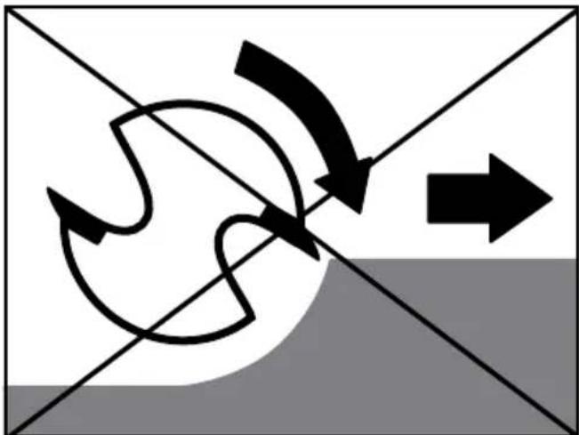
natural_image
Abstract diagram with curved arrows and a right-pointing arrow, no text or symbols present- Millingprocess
Set the milling depth as previously described.
Place the device on the desired work-piece and switch it on.
☐ Loosen the clamping level by turning it clockwise and pushing the device down until it touches the surface of the depth stop 12 on the step stop 9.
☐ Lock the device into place by turning the clamp lever 16 anti-clockwise.
□ Mill with even speed and even pressure (see fig. 1).
- Set the copy casing
Set the copy casino from below on the sliding bar 8.
Secure the copy casing with the two screws of the extractor adapter on the base plate 7. Ensure that the copy casing is set the right way round - the thrust ring 25 must be pointing down (see fig. D).
- Milling with the copy casing
Note! The pattern must be at least as high as the copy casing's 26 thrust ring 25.
Note! Chose the router bit as small as the inner diameter of the copy casing.
When using a copy casing 26 the pattern can be transferred onto the work piece.
Place the router with the copy casing on the pattern.
☐ Loosen the clamping level by turning it clockwise and lower the device until it reaches predetermined depth.
☐ Lead the device with the protecting copy casing along the pattern. Apply pressure lightly.
- Milling with a rip fence
☐ Push the rip fen along the guide rail of the base plate and tighten the screws.
Put the rip fen on the edge of the work piece (see fig. F, H).
- Milling with a circular compass (see fig. J)
☐ Put the centring p30 in the marked mid point of the circle.
Turn the rip fence over, i.e. the fence side is facing upwards.
☐ Screw together the centre pin and the rip fence with a wing bolt. Lock the centre pin to the screws with the slot of the open-ended spanner 27.
● Maintenance and Cleaning
WARNING! RISK OF INJURY! Switch the device off and pull the plug out of the mains socket before carrying out any work on the device.
□ Always keep the device clean, dry and free of oil or grease.
☐ Use a dry cloth to clean the housing.
WARNING! If the connection cable needs to be replaced, this repair must be performed by the manufacturer or a representative to prevent safety hazards.
Note: Spare parts not listed (e.g. carbon brushes, switches) can be ordered through our call centre.
Warranty
The warranty for this appliance is for 3 years from the date of purchase. The appliance has been manufactured with care and meticulously examined before delivery. Please retain your receipt as proof of purchase. In the event of a warranty claim, please make contact by telephone with our Service Department. Only in this way can a post-free despatch for your goods be assured.
The warranty covers only claims for material and manufacturing defects, but not for transport damage, for wearing parts or for damage to fragile components, e.g. buttons or batteries. This product is for private use only and is not intended for commercial use.
The warranty is void in the case of abusive and improper handling, use of force and internal tampering not carried out by our authorized service branch. Your statutory rights are not restricted in any way by this warranty.
The warranty period will not be extended by repairs made unter warranty. This applies also to replaced and repaired parts. Any damage and defects extant on purchase must be reported immediately after unpacking the appliance, at the latest, two days after the purchase date. Repairs made after the expiration of the warranty period are subject to payment.
GB
Service Great Britain
Tel.: 0871 5000 720
(0.10 GBP/Min.)
e-mail: kompernass@lidl.co.uk
IAN 100129

Disposal

The packaging is wholly composed of environmentally-friendly materials that can be disposed of at a local recycling centre.

Do not dispose of electrical power tools with the household rubbish!
In accordance with European Directive 2012 / 19 / EU, worn out electrical power tools must be collected separately and taken for environmentally compatible recycling.
Contact your local refuse disposal authority for more details of how to dispose of your worn-out devices.

Translation of the original declaration of conformity / Manufacturer CE
We, KOMPERNASS HANDELS GMBH, the person responsible for documents: Mr Semi Uguzlu, BURG-STRASSE 21, 44867 BOCHUM, GERMANY, hereby declare that this product complies with the following standards, normative documents and EU directives:
Machinery Directive (2006/42/EC)
EU Low Voltage Directive (2006/95/EC)
Electromagnetic Compatibility (2004/108/EC)
RoHS Directive (2011/65/EU)
Applicable harmonized standards
EN 60745-1:2009+A11
EN 60745-2-17:2010
EN 55014-1:2006+A1+A2
EN 55014-2:1997+A1+A2
EN 61000-3-2:2006+A1+A2
EN 61000-3-3:2008
Type / Device description:
Router POF 1200 A1
Date of manufacture (DOM): 06-2014 Serial number: IAN 100129
Bochum, 30.06.2014

text_image
JeddyushSemi Uguzlu
- Quality Manager -
We reserve the right to make technical modifications in the course of further development.
KOMPERNASS HANDELS GMBH
BURGSTRASSE21
44867BOCHUM
GERMANY