
TRX 3000 - Radio BRENNENSTUHL - Free user manual and instructions
Find the device manual for free TRX 3000 BRENNENSTUHL in PDF.

| Product type | PMR 8-channel walkie-talkie |
| Brand | Brennenstuhl |
| Model | TRX 3000 |
| Number of channels | 8 channels (446.00625 - 446.09375 MHz) |
| Maximum range | Up to 5 km (depending on conditions) |
| Power supply | 4 AAA batteries (1.5 V) or mains adapter 7.5 V / 200 mA (optional) |
| Dimensions (approx.) | 160 x 55 x 35 mm |
| Weight (with batteries) | Approx. 200 g |
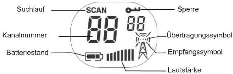
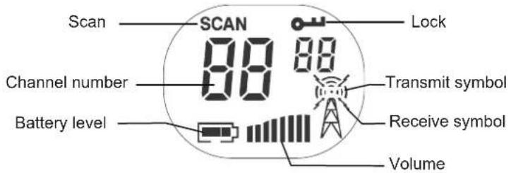
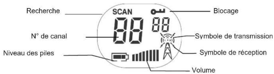
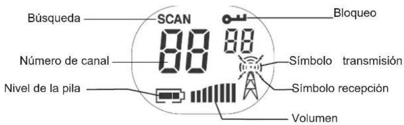
| Display | LCD screen with channel, volume, battery and function indicators |
| Main functions | Voice communication, call tone, automatic squelch, monitor (squelch defeat), channel scan, key lock, Roger beep (end of transmission), key tone |
| Volume control | UP/DOWN keys with bar display |
| Call tone selection | 5 available call tones or deactivation |
| Automatic standby function | Standby after 4 seconds of inactivity to save batteries |
| External jack | Jack for external microphone/speaker (optional) |
| Included accessories | 2 walkie-talkies, 2 belt clips, user manual |
| Care and cleaning | Wipe with a soft, dry cloth. Remove batteries when not in use for extended periods. |
| Safety | Only use alkaline or rechargeable AAA batteries. Do not expose to water, fire or high temperatures. |
| Warranty | 2 years manufacturing defects (except improper use) |
Frequently Asked Questions - TRX 3000 BRENNENSTUHL
User questions about TRX 3000 BRENNENSTUHL
0 question about this device. Answer the ones you know or ask your own.
Ask a new question about this device
Download the instructions for your Radio in PDF format for free! Find your manual TRX 3000 - BRENNENSTUHL and take your electronic device back in hand. On this page are published all the documents necessary for the use of your device. TRX 3000 by BRENNENSTUHL.
USER MANUAL TRX 3000 BRENNENSTUHL
natural_image
Line drawing of a walkie-talkie and its side view (no text or symbols)2. Bestandteile
natural_image
Technical line drawings of a device with internal components and mounting holes (no text or symbols)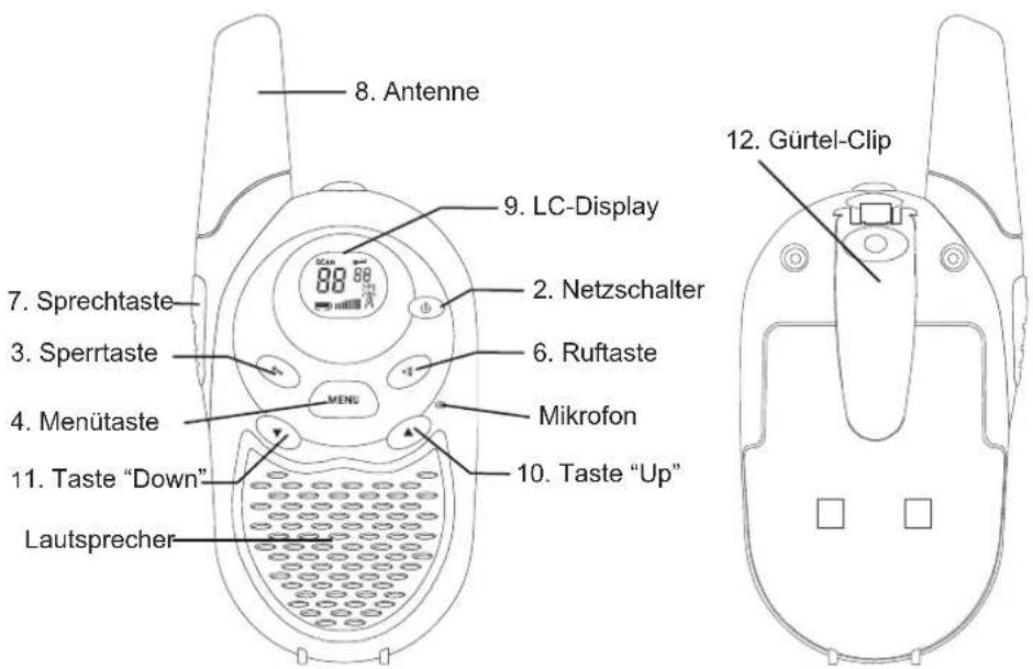
natural_image
Line drawing of a handheld device with a label and directional arrow (no text or symbols)
natural_image
Line drawing of a portable electronic device with a handle and label (no readable text or symbols)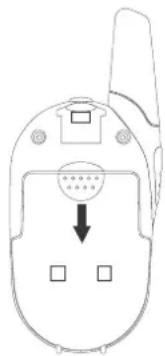
natural_image
Line drawing of a flip phone with an arrow pointing to the bottom panel (no text or symbols present)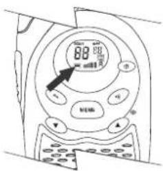
Kanalfeststellung
natural_image
Line drawing of a portable device with a circular button and handle (no text or symbols)Controls and displays.... 16
-
Component Guide.... 17
-
Starting to use your PMR radio 18
Installing the batteries 18
- Operation.... 19
Switching on your PMR radio.... 19
Communication....19
Adjusting the speaker volume 20
Channel selection 20
To speak to another radio, 20
Calling another radio.... 21
Adjusting the call tone.... 21
Beep tone ON/OFF 22
End of communication signal (roger) ON/OFF 22
- Other features.... 22
Automatic squelch.... 22
Channel lock 23
Channel scan....23
Automatic standby feature 23
External microphone/loudspeaker....23
-
Customer services 24
-
Channel frequencies and code charts.... 24
PMR channel frequencies.... 24
- Warranty 24
1. General notes
Pack contents
On unpacking your PM radio, you should find the following items:
- Two 8-channel PMR radios
- Two belt clips (attached)
- This manual
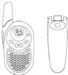
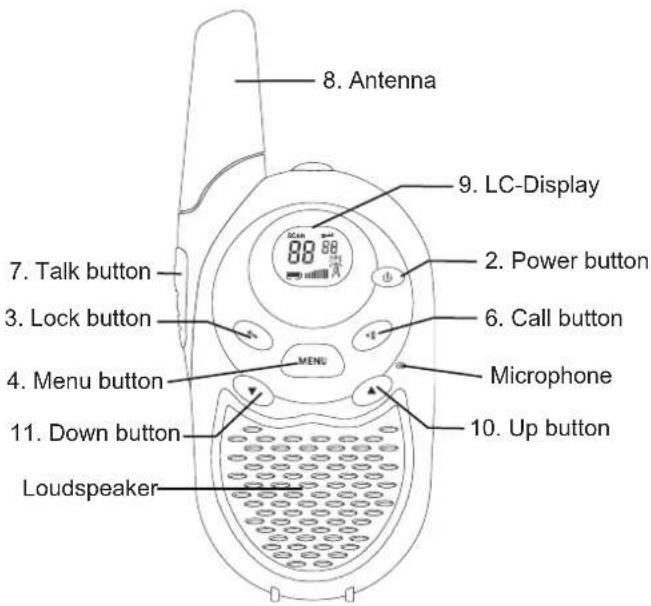
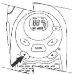
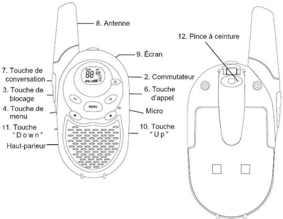
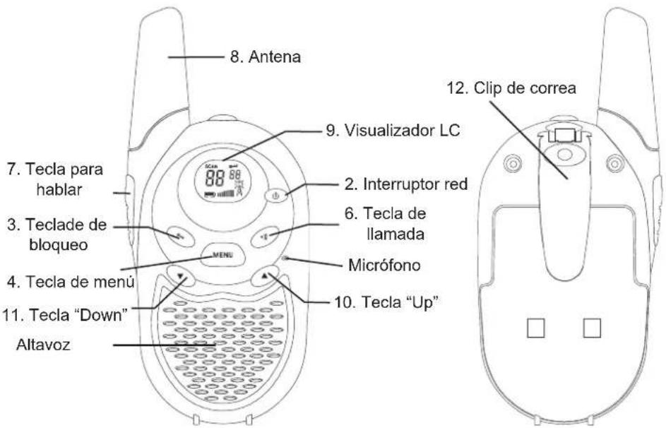
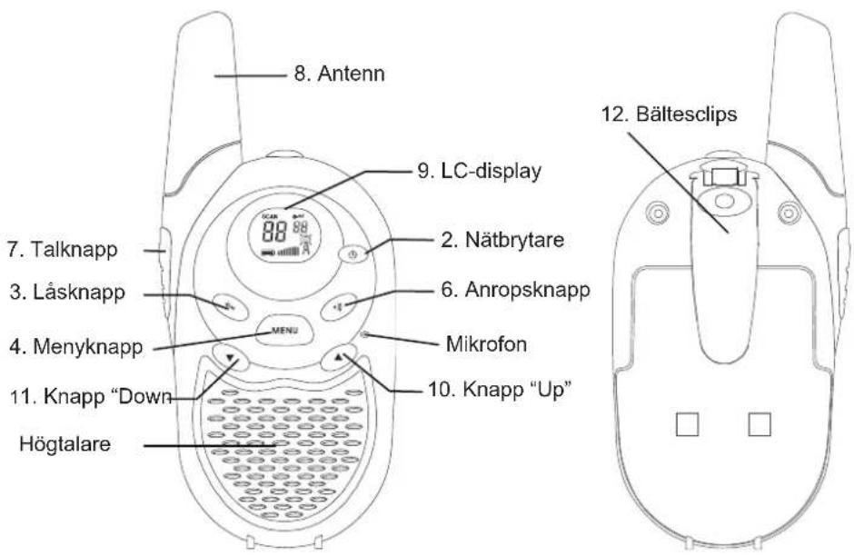
Controls and displays
- Loudspeaker/microphone jack
- Power button
- Lock button
- Menu button
- Charging jack
- Call button
- Talk button
- Antenna
- LC-Display
- Up button (channel change and volume control)
- Down button (channel change and volume control)
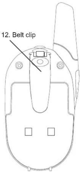
- Belt clip
natural_image
Line drawing of a walkie-talkie and its side view (no text or symbols)2. Component Guide
- Loudspeaker/microphone 5. Charging jack
natural_image
Technical line drawings of a device with internal components and mounting holes (no text or symbols)
3. Starting to use your PMR radio
Installing the batteries
To use the radio, install four AAA batteries.
Caution!
Incorrect positioning of the batteries can damage both the batteries and the unit.
To install the batteries
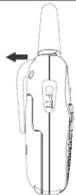
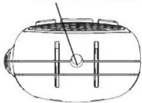
Remove the belt clip. To do this, pull back the tab on the top of the clip, raise the cover and pull off.
Pull the battery compartment lock downwards and release the battery cover.
Insert four AAA batteries.
Position the batteries according to the polarity markings on the plastic. Replace the battery cover.
Snap the lock tab and belt clip back into place.
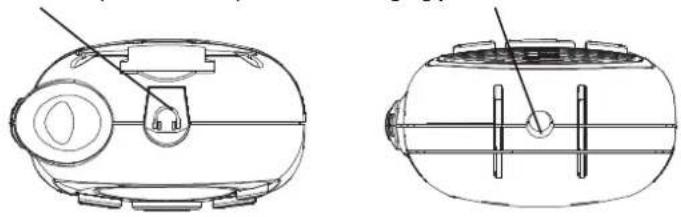
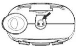
Connecting the adapter
Lift the rubber flap on the top of the unit to expose the jack.
To operate the unit on AC/DC, a suitable adapter is required (option) to charge rechargeable batteries.
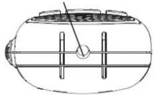
Insert the round connector (OD 2.5 mm) of the
7.5 V DC/200 mA AC/DC adapter* into the charging jack on bottom side of the unit.
Note
The unit should be switched off in order to charge the batteries properly. If the unit is left switched on the charge current will be too low to charge the batteries, as the unit will still be using power.
There is no charge indicator during charging in the off mode. It takes 7-10 hours to fully charge the batteries if they are at their lowest level.
natural_image
Line drawing of a handheld device with a label 'O' and an arrow indicating left motion (no text or symbols on the device itself)
natural_image
Line drawing of a handheld device with a labeled grip and arrow indicator (no text or symbols)
natural_image
Line drawing of a mobile phone connector with a circular socket and four ports (no text or symbols)WARNING
For the charging process using an AC/DC adapter, use only rechargeable AAA-type batteries. No rechargeable batteries will be damaged beyond use and damage the unit (risk of explosion)!
Do not mix old and new batteries.
Do not mix alkaline batteries, standard (carbon-zinc) and rechargeable batteries.
* The AC/DC adapter and rechargeable batteries are sold separately.

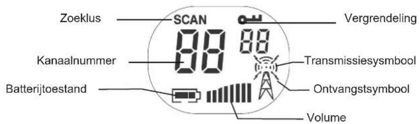
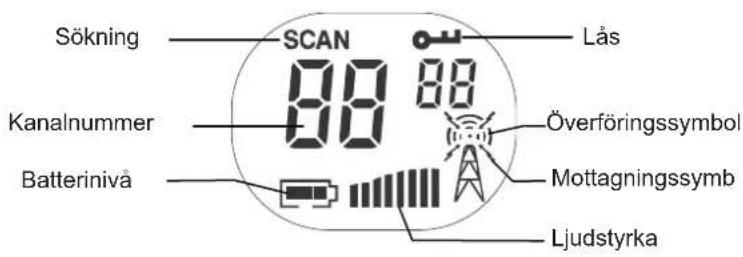
Battery meter
The battery meter is located in the bottom left corner of the LC display on the unit. The symbol looks like a battery with vertical hatching. As the power is used, the bar will disappear.
Low battery indicator
When the batteries need to be changed, the hatching will disappear. To ensure uninterrupted communication, replace the batteries as soon as possible.
Note
Always use alkaline batteries for replacements. If you do not intend to use the radio for any length of time, remove the batteries. Batteries may corrode and leak when left unused for prolonged periods and permanently damage your radio.
Do not put batteries into a fire or expose them to high heat. They may explode!
4. Operation
Switching on your PMR radio
To switch the radio on or off, press and hold the power button for at least 2 seconds. The unit will bleep, the LCD panel will display information about your radio and the panel will be illuminated by a green light for several seconds.
Communication
You can communicate in two directions with your new PMR radio. Eight channels are available. You can either talk directly to others and hear their response or call them with an audible tone.
PMR radios can only communicate when either the TALK button (for speech) or the CALL button (for paging) is pressed. The unit can only receive when both buttons are fully released.
Receiving communications
When your radio is switched on and is not being used to transmit voice communication or for paging, it will always be in the receiving mode.
You cannot receive any transmissions when the TALK or CALL button is pressed, even if you are not speaking.
Pressing these buttons automatically switches off the receiving mode.
If you are using the unit for conversational purposes, you must release the TALK and/or CALL button to be able to hear the responses of the other person.
Failure to do so will mean that the unit stays in the transmission mode, preventing you from hearing communications from other units.
Confirmation signal for end of communication (roger)
When the person talking to you from another radio finishes speaking and releases his TALK button, you will hear a tone from your own unit indicating that the other radio is now in the receiving mode and you can begin your transmission.
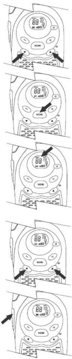
Adjusting the speaker volume
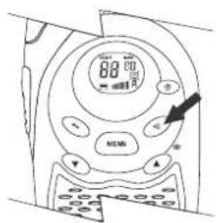
The UP and DN (DOWN) buttons control the volume, change channels and codes, and program the radio.
- Press the UP button to increase volume.
- Press the DN button to reduce volume.
- The volume level is indicated by the number of bars in the LC display.
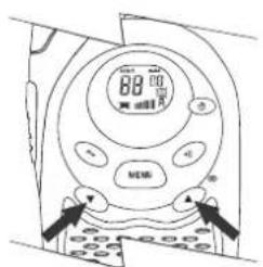
Channel selection
Your PMR operates on one of the eight preset channels. You can only make contact with other radios set to the same channel as yours. The chart on page 24 gives the frequencies on which your radio can operate.
To change the channel:
- Press the MENU (channel set) button. The »1 ^ch « symbol will flash in the display.
- While the number is flashing, press the UP or DN button until the desired channel appears.
To set the channel, press the MENU button (channel set) again.
- If you do not press the MENU button a second time, the unit will automatically revert to normal operation after ten seconds.
To speak to another radio,
- Turn the volume up to an audible level.
- Press the TALK button on the left side of the unit. The symbol for talk transmission will appear in the LC display.
- While pressing the talk button, speak into the microphone with your mouth 4 – 5 cm from the unit.
- When you finish speaking, release the TALK button immediately to hear the response.
Range
Your PMR radio has a range of up to 5 km. This, however, can be reduced by certain atmospheric and environmental conditions.
The range can be affected by:
• Buildings
- Dense trees or foliage
• Hilly or mountainous terrain
The longest range is achieved in flat, open terrain, without obstructions. Select Monitor function to override the automatic squelch function will help to extend the range to the maximum limits.
The range also depends on the state of the battery of the radio, the type of terrain in your location and the strength of the signal from the transmitting radio.
Calling another radio
To page or call someone,
- Make sure both units are switched on.
- Turn up the volume to an audible level.
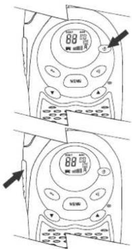
- Press and release the CALL button on the front of your radio.
The other unit will generate a call tone lasting two seconds. Your call can now be answered as follows:
- Press the TALK button and speak into the radio
- Press the CALL button. This will activate a call signal lasting two seconds on your radio.
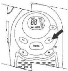
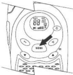
Adjusting the call tone
Press the MENU button twice. Your PMR unit will now go into the call tone setting mode.
»CR1« appears in the LC display.
To change the call tone number (5 different tones) or to switch off the call tone, press UP or DN. During this process, the different call tones can be heard.
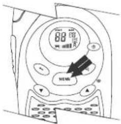
This feature allows the radio to sound a confirmation beep tone whenever a button is pressed.
To switch the bleep tone on or off, proceed as follows:
- Press the MENU button three times until the »to symbol flashes in the LC display.
- Press the UP or DN button to enable (»ON« appears in the display) or disable (»OF« appears in the display) the bleep tone feature.
- To exit the selection mode, press the TALK button once.
End of communication signal (roger) ON/OFF
The roger signal will be automatically transmitted as soon as the TALK button is released. This lets the other person know that you have finished transmitting your message.
To enable or disable the roger signal:
- Press the MENU button four times until the »ro symbol appears flashing in the LC display.
- Press the UP or DN button to enable (»ON« appears in the LC display) or disable (»OF« appears in the display) the roger signal.
• To exit the roger signal feature, press the TALK button.
5. Other features
Automatic squelch
Your PMR is fitted with automatic squelch circuitry which filters out weak transmissions and unwanted extraneous noise.
These signals may be picked up as background static and are usually caused by the nature of the terrain or the fact that your radio is at the limit of its range.
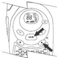
Monitor
With this function, you can switch off the automatic squelch feature, temporarily or permanently. In this way, the maximum possible range of your radio can be used, but it may pick up static signals as well. You can adjust the speaker volume by the noise of the static.
- Press MENU and UP button simultaneously. The monitor signals will appear in the LC display.
- Press MENU the button to restore the automatic squelch function.
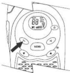
Channel lock
This feature locks the channel adjustment buttons on the front of the unit so that the channel settings cannot be changed unintentionally.
To lock a channel:
- Press and hold the LOCK button for five seconds until you hear a bleep tone. The locking symbol (shaped like a key) will appear in the LC display.
To unlock a channel:
- Press the LOCK button again for five seconds until you hear a bleep tone. The lock symbol in the LC display will disappear.
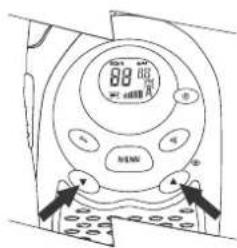
Channel scan
Your radio can scan its eight channels for any activity. This allows you to find other radios without having to change channels.
To scan:
- Press and hold the MENU and DN buttons simultaneously for two seconds.
- The channel display will change as it scans through the channels.
- If a signal is detected, the unit will pause and listen for four seconds.
- Press the TALK button to stop the scan and communicate or the DN button to continue the scan.
- To stop the scan, press the MENU button again.
Automatic standby feature
Your PMR unit is fitted with special circuitry designed to extend the life of your battery. If the radio is not used for four seconds, it will automatically go into the standby mode. This will not affect the ability of the radio to receive transmissions. If a signal is detected, it will automatically return to full power.
natural_image
Line drawing of a device casing with a handle and control knob (no text or symbols)External microphone/loudspeaker
Your PMR radio can be used with an optional external microphone and loudspeaker*, which are usually sold together. The jacks are located under the protective cover on the top of the unit.
To connect an external loudspeaker/microphone headset:
- Lift the rubber flap on the top of the unit to expose the jack.
- Insert the appropriate plug into the correct jack.
6. Customer services
Thank you for purchasing this PMR radio. You have acquired a high-quality item of communicating equipment which will give you many years of reliable service. Please read these instructions carefully.
Should you encounter any problems with the product or have any queries about its functions, please refer to this manual first.
7. Channel frequencies and code charts
PMR channel frequencies
| Channel | Frequency | (MHz) | Channel | Frequency(MHz) |
| 1 | 446.00625 | 5 | 446.05625 | |
| 2 | 446.01875 | 6 | 446.06875 | |
| 3 | 446.03125 | 7 | 446.08125 | |
| 4 | 446.04375 | 8 | 446.09375 |
8. Warranty
Brennenstuhl warrants this unit to be free from defects in material and/or workmanship for a period of 2 years. This warranty does not cover second-hand ownership or products that are purchased for sale or leasing to a third party. Nor does the warranty cover damage resulting from acts of God, the effects of lightning, misuse, improper installation or operation, or unauthorized repair or alterations.
Claims under the warranty will only be recognized if supported by proof of purchase. We strongly recommend, therefore, that you keep your sales receipt and all the packing materials in order to take advantage of the limited warranty. When returning the product to an authorized service centre (see below), include all the accessories and the user's manual. Also, do not forget to include your name and address (please print), a brief description of the defect and a copy of the sales receipt.
brennenstuhl®
natural_image
Line drawing of a walkie-talkie and its side view (no text or symbols)2. Composants
natural_image
Line drawing of a portable device with a handle and control panel (no text or symbols)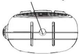
natural_image
Technical line drawing of a cylindrical device with internal components and a pointer (no text or symbols)
natural_image
Line drawing of a device with a nozzle and labeled grip (no text or symbols)natural_image
Line drawing of a mobile phone with a circular button and square buttons, no text or symbols presentAVERTISSEMENT
Mise en marche du talkie-walkie PMR
natural_image
Line drawing of a walkie-talkie and its side view (no text or symbols)2. Onderdelen
natural_image
Line drawing of a portable device with a handle and control panel (no text or symbols)natural_image
Technical line drawing of a cylindrical device with internal components and a pointer (no text or symbols)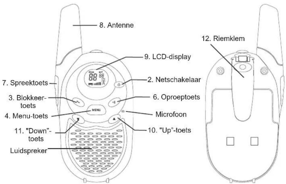
natural_image
Line drawing of a handheld device with a label and directional arrow (no text or symbols)
natural_image
Line drawing of a handheld electronic device with a labeled grip and arrow indicator (no text or symbols beyond the label)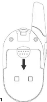
natural_image
Line drawing of a mobile phone casing with a circular button and two square buttons, no text or symbols present.
3 keer
Toetstoon AAN/UIT
4 keer
Bevestigingssignaal(Roger) AAN/UIT
natural_image
Line drawing of a device with a knob and handle (no text or symbols)natural_image
Line drawing of a walkie-talkie and its side view (no text or symbols)2. Elementos componentes
natural_image
Line drawing of a robotic vacuum cleaner with a handle and control panel (no text or symbols)- Hembrilla de carga
natural_image
Technical line drawing of a cylindrical device with internal components and a pointer (no text or symbols)
natural_image
Line drawing of a handheld device with a label 'OPTO' and an arrow pointing to it (no readable text or symbols beyond the label)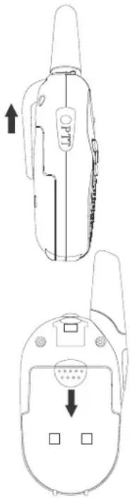
natural_image
Line drawing of a portable electronic device with a handle and control panel (no text or symbols)Colocar as pilhas 62
- Operação.... 63
natural_image
Line drawing of a walkie-talkie and its side view (no text or symbols)natural_image
Technical line drawings of a device with front and side views (no text or symbols)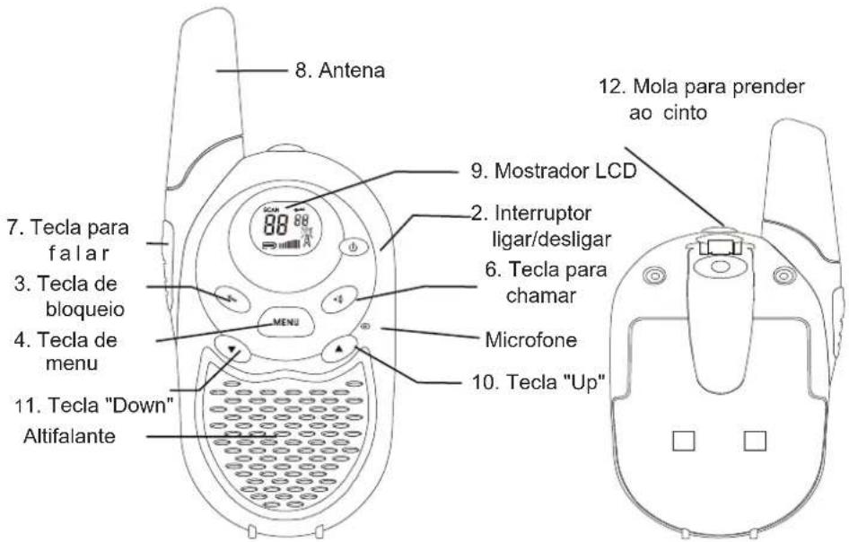
natural_image
Line drawing of a handheld device with internal components and an arrow indicating left motion (no text or symbols)
natural_image
Line drawing of a portable thermosorbent device with no visible text or symbols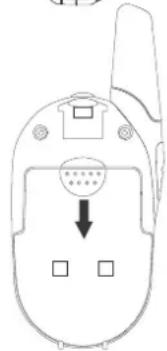

Indicador da carga das pilhas
3 vezes
Busca de canais
natural_image
Line drawing of a portable device with a handle and circular button (no text or symbols)natural_image
Line drawing of a walkie-talkie and its side view (no text or symbols)2. Beståndsdelar
natural_image
Technical line drawings of a device casing and its internal components (no text or symbols)
natural_image
Line drawing of a handheld device with a label and directional arrow (no text or symbols)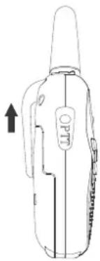
natural_image
Line drawing of a portable electronic device with a handle and label (no readable text or symbols)
natural_image
Line drawing of a flip phone with a circular button and three square buttons, no text or symbols present.
Batterimätanordning
Automatisk standby-koppling
natural_image
Line drawing of a portable device with a handle and control knob (no text or symbols)Extern enhet mikrofon/högtalare
natural_image
Line drawing of a walkie-talkie with a digital display and speaker grille (no text or symbols)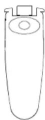
2. Τμήματα

natural_image
Line drawing of a portable electronic device with a handle and control panel (no text or symbols)- ]ποδοχή φόρτισης
natural_image
Technical line drawing of a cylindrical mechanical component with internal channels and a central hub (no text or symbols)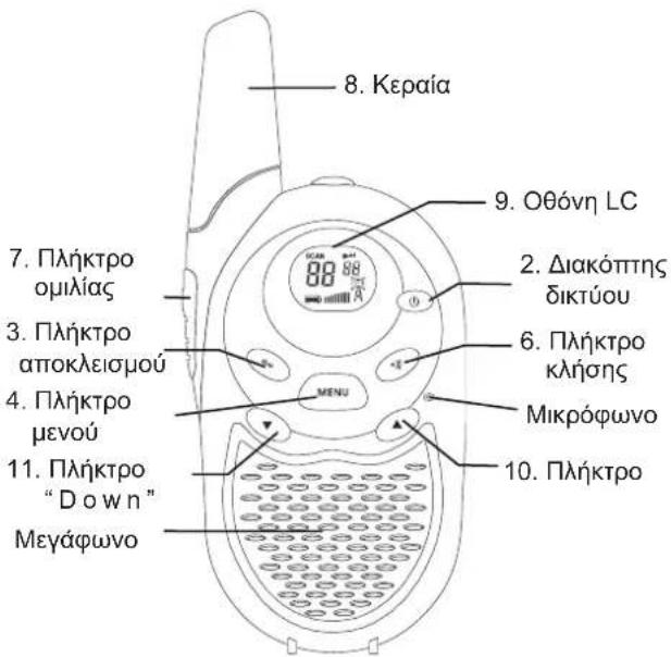
natural_image
Line drawing of a portable device with a circular button and handle (no text or symbols)scatter
| X | Y | |---|---| | 0.1 | 0.5 | | 0.2 | 0.6 | | 0.3 | 0.7 | | 0.4 | 0.8 | | 0.5 | 0.9 | | 0.6 | 1.0 | | 0.7 | 1.1 | | 0.8 | 1.2 | | 0.9 | 1.3 | | 1.0 | 1.4 | | 1.1 | 1.5 | | 1.2 | 1.6 | | 1.3 | 1.7 | | 1.4 | 1.8 | | 1.5 | 1.9 | | 1.6 | 2.0 | | 1.7 | 2.1 | | 1.8 | 2.2 | | 1.9 | 2.3 | | 2.0 | 2.4 | | 2.1 | 2.5 | | 2.2 | 2.6 | | 2.3 | 2.7 | | 2.4 | 2.8 | | 2.5 | 2.9 | | 2.6 | 3.0 | | 2.7 | 3.1 | | 2.8 | 3.2 | | 2.9 | 3.3 | | 3.0 | 3.4 | | 3.1 | 3.5 | | 3.2 | 3.6 | | 3.3 | 3.7 | | 3.4 | 3.8 | | 3.5 | 3.9 | | 3.6 | 4.0 | | 3.7 | 4.1 | | 3.8 | 4.2 | | 3.9 | 4.3 | | 4.0 | 4.4 | | 4.1 | 4.5 | | 4.2 | 4.6 | | 4.3 | 4.7 | | 4.4 | 4.8 | | 4.5 | 4.9 | | 4.6 | 5.0 | | 4.7 | 5.1 | | 4.8 | 5.2 | | 4.9 | 5.3 | | 5.0 | 5.4 | | 5.1 | 5.5 | | 5.2 | 5.6 | | 5.3 | 5.7 | | 5.4 | 5.8 | | 5.5 | 5.9 | | 5.6 | 6.0 | | 5.7 | 6.1 | | 5.8 | 6.2 | | 5.9 | 6.3 | | 6.0 | 6.4 | | 6.1 | 6.5 | | 6.2 | 6.6 | | 6.3 | 6.7 | | 6.4 | 6.8 | | 6.5 | 6.9 | | 6.6 | 7.0 | | 6.7 | 7.1 | | 6.8 | 7.2 | | 6.9 | 7.3 | | 7.0 | 7.4 | | 7.1 | 7.5 | | 7.2 | 7.6 | | 7.3 | 7.7 | | 7.4 | 7.8 | | 7.5 | 7.9 | | 7.6 | 8.0 | | 7.7 | 8.1 | | 7.8 | 8.2 | | 7.9 | 8.3 | | 8.0 | 8.4 | | 8.1 | 8.5 | | 8.2 | 8.6 | | 8.3 | 8.7 | | 8.4 | 8.8 | | 8.5 | 8.9 | | 8.6 | 9.0 | | 8.7 | 9.1 | | 8.8 | 9.2 | | 8.9 | 9.3 | | -0.1 | -0.5 | | -0.2 | -0.6 | | -0.3 | -0.7 | | -0.4 | -0.8 | | -0.5 | -0.9 | | -0.6 | -1.0 | | -0.7 | -1.1 | | -0.8 | -1.2 | | -0.9 | -1.3 | | -1.0 | -1.4 | | -1.1 | -1.5 | | -1.2 | -1.6 | | -1.3 | -1.7 | | -1.4 | -1.8 | | -1.5 | -1.9 | | -1.6 | -2.0 | | -1.7 | -2.1 | | -1.8 | -2.2 | | -1.9 | -2.3 | | -2.0 | -2.4 | | -2.1 | -2.5 | | -2.2 | -2.6 | | -2.3 | -2.7 | | -2.4 | -2.8 | | -2.5 | -2.9 | | -2.6 | -3.0 | | -2.7 | -3.1 | | -2.8 | -3.2 | | -2.9 | -3.3 | | -3.0 | -3.4 | | -3.1 | -3.5 | | -3.2 | -3.6 | | -3.3 | -3.7 | | -3.4 | -3.8 | | -3.5 | -3.9 | | -3.6 | -4.0 | | -3.7 | -4.1 | | -3.8 | -4.2 | | -3.9 | -4.3 | | -4.0 | -4.4 | | -4.1 | -4.5 | | -4.2 | -4.6 | | -4.3 | -4.7 | | -4.4 | -4.8 | | -4.5 | -4.9 | | -4.6 | -5.0 | | -4.7 | -5.1 | | -4.8 | -5.2 | | -4.9 | -5.3 | | -5 | -5 | The chart contains two data points: one marked with a circle and the other with a cross, both located at the top of the chart in the upper right corner (labeled as '●'). The bottom row contains the number '9' in the bottom left corner.91
