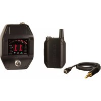
GLXD16 - Wireless audio equipment SHURE - Free user manual and instructions
Find the device manual for free GLXD16 SHURE in PDF.



| Product Type | Digital wireless guitar system (pedal receiver + beltpack transmitter) |
| Brand | Shure |
| Model | GLXD16 |
| Receiver (pedal) dimensions | 46 x 95 x 133 mm (H x W x D) |
| Receiver weight | 504 g |
| Receiver power supply | 9 to 15 V DC, 250 mA min, 400 mA max (compatible with positive or negative tip) |
| Transmitter (beltpack) dimensions | 90 x 65 x 23 mm (H x W x D) without antenna |
| Transmitter power supply | Rechargeable Li-ion battery 3.7 V (SB902), up to 16 h battery life |
| Frequency band | 2.4 GHz (ISM, license-free) |
| Typical range | 60 m (200 ft) |
| Audio frequency response | 20 Hz – 20 kHz |
| Dynamic range | 120 dB (A-weighted) |
| Total harmonic distortion | 0.2% typical |
| Transmitter gain | -20 to +40 dB in 1 dB steps |
| Key features | Digital wireless transmission, built-in chromatic tuner, automatic frequency hopping, automatic linking, remote identification, control lock, multi-receiver compatibility (up to 8) |
| Care and cleaning | Clean with a dry cloth; do not use near water; do not block ventilation openings |
| Safety | Do not open, do not expose to heat (>60°C), use only Shure batteries and accessories, follow grounding instructions |
| Spare parts and repairability | Battery SB902, USB charger SBC-USB, power supply PS23, guitar cable WA305; repair by qualified personnel only |
| General information | Compliant with FCC and IC, Class B, worldwide license-free operation in the 2.4 GHz band |
Frequently Asked Questions - GLXD16 SHURE
User questions about GLXD16 SHURE
0 question about this device. Answer the ones you know or ask your own.
Ask a new question about this device
Download the instructions for your Wireless audio equipment in PDF format for free! Find your manual GLXD16 - SHURE and take your electronic device back in hand. On this page are published all the documents necessary for the use of your device. GLXD16 by SHURE.
USER MANUAL GLXD16 SHURE
GLX-D Wireless System – GLXD6 Guitar Pedal Receiver
natural_image
Black electronic device labeled 'SHURE' with no visible text or symbols on its body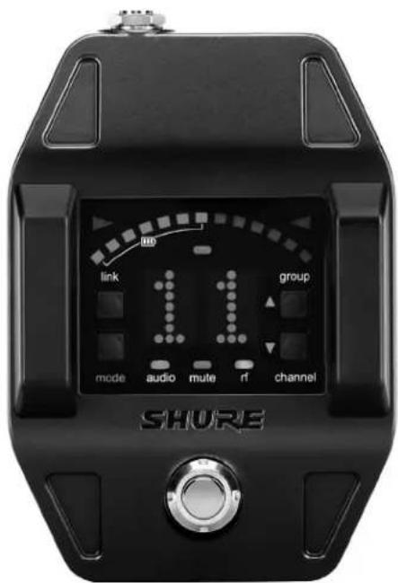
User Guide
IMPORTANT SAFETY INSTRUCTIONS
- READ these instructions.
- KEEP these instructions.
- HEED all warnings.
- FOLLOW all instructions.
- DO NOT use this apparatus near water.
- CLEAN ONLY with dry cloth.
- DO NOT block any ventilation openings. Allow sufficient distances for adequate ventilation and install in accordance with the manufacturer's instructions.
- DO NOT install near any heat sources such as open flames, radiators, heat registers, stoves, or other apparatus (including amplifiers) that produce heat. Do not place any open flame sources on the product.
- DO NOT defeat the safety purpose of the polarized or groundingtype plug. A polarized plug has two blades with one wider than the other. A grounding type plug has two blades and a third grounding prong. The wider blade or the third prong are provided for your safety. If the provided plug does not fill into your outlet, consult an electrician for replacement of the obsolete outlet.
- PROTECT the power cord from being walked on or pinched, particularly at plugs, convenience receptacles, and the point where they exit from the apparatus.
- ONLY USE attachments/accessories specified by the manufacturer.
- USE only with a cart, stand, tripod, bracket, or table specified by the manufacturer, or sold with the apparatus. When a cart is used, use caution when moving the cart/apparatus combination to avoid injury from tip-over.
-
UNPLUG this apparatus during lightning storms or when unused for long periods of time.
-
REFER all servicing to qualified service personnel. Servicing is required when the apparatus has been damaged in any way, such as power supply cord or plug is damaged, liquid has been spilled or objects have fallen into the apparatus, the apparatus has been exposed to rain or moisture, does not operate normally, or has been dropped.
- DO NOT expose the apparatus to dripping and splashing. DO NOT put objects filled with liquids, such as vases, on the apparatus.
- The MAINS plug or an appliance coupler shall remain readily operable.
- The airborne noise of the Apparatus does not exceed 70dB (A).
- Apparatus with CLASS I construction shall be connected to a MAINS socket outlet with a protective earthing connection.
- To reduce the risk of fire or electric shock, do not expose this apparatus to rain or moisture.
- Do not attempt to modify this product. Doing so could result in personal injury and/or product failure.
- Operate this product within its specified operating temperature range.

This symbol indicates that dangerous voltage constituting a risk of electric shock is present within this unit.

This symbol indicates that there are important operating and maintenance instructions in the literature accompanying this unit.
WARNING: This product contains a chemical known to the State of California to cause cancer and birth defects or other reproductive harm.
CONSIGNES DE SÉCURITÉ IMPORTANTES
WARNING: Battery packs shall not be exposed to excessive heat such as sunshine, fire, or the like.
WARNING
- Battery packs may explode or release toxic materials. Risk of fire or burns. Do not open, crush, modify, disassemble, heat above 140^ (60^) , or incinerate
• Follow instructions from manufacturer - Never put batteries in mouth. If swallowed, contact your physician or local poison control center
- Do not short circuit; may cause burns or catch fire
- Do not charge or use battery packs with other than specified Shure products
- Dispose of battery packs properly. Check with local vendor for proper disposal of used battery packs
WARNING: Danger of explosion if battery incorrectly replaced. Operate only with Shure compatible batteries.

Note:
• This equipment is intended to be used in professional audio applications.
- EMC conformance is based on the use of supplied and recommended cable types. The use of other cable types may degrade EMC performance.
- Use this battery charger only with the Shure charging modules and battery packs for which it is designed. Use with other than the specified modules and battery packs may increase the risk of fire or explosion.
• Changes or modifications not expressly approved by Shure Incorporated could void your authority to operate this equipment.

Note: Use only with the included power supply or a Shure-approved equivalent.

The new groundbreaking GLX-D Wireless Systems from Shure combine the leading edge of Automatic Frequency Management technology with best-in-class intelligent lithium ion battery rechargeability, world-renowned microphones and unparalleled design and construction. The compact low-profile design easily fits into pedalboard configurations. Built-in chromatic tuner simplifies setups while offering flexible tuning options. Advanced frequency hopping technology detects interference and automatically switches to a clear backup channel to prevent audio dropouts. Channel scanning finds the best receiver channel for wireless audio and automatically links to the transmitter.
• Exceptional digital audio clarity
• Built-in tuner with customizable functionality and display options
- Operates in 2.4 GHz spectrum, available worldwide.
- Compact rugged metal construction
- Receiver compatible with standard 9 V DC positive tip or negative tip power supplies (250 mA minimum)
- Rechargeable transmitter batteries deliver cost-efficiency and up to 16 hours of runtime
- Adjustable transmitter gain to optimize audio signal
• Automatically detects and avoids interference to preserve audio quality
• RF back-channel for remote control of transmitter functions - Automatic transmitter power-off to conserve battery life when transmitter is not in use.
Included Components
| Shure Rechargeable Battery SB902 | |
| Micro USB Battery Charger SBC-USB | |
| Power Supply PS23 | |
| Premium Guitar Cable WA305 | |
Optional Accessories
| Car Battery Charger SBC-CAR | |
| Stand Alone Single Battery Charger | SBC-902 |
Quick Start
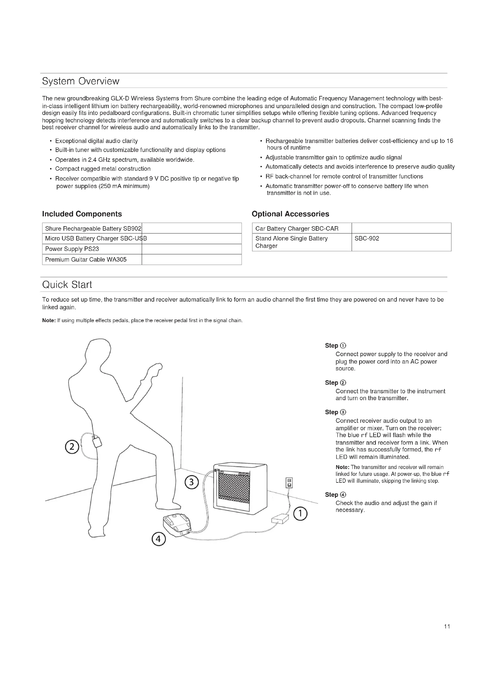
To reduce set up time, the transmitter and receiver automatically link to form an audio channel the first time they are powered on and never have to be linked again.
Note: If using multiple effects pedals, place the receiver pedal first in the signal chain.
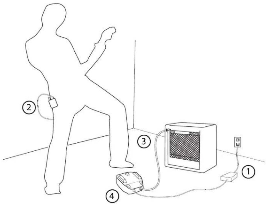
Step ①
Connect power supply to the receiver and plug the power cord into an AC power source.
Step ②
Connect the transmitter to the instrument and turn on the transmitter.
Step ③
Connect receiver audio output to an amplifier or mixer. Turn on the receiver: The blue rf LED will flash while the transmitter and receiver form a link. When the link has successfully formed, the rf LED will remain illuminated.
Note: The transmitter and receiver will remain linked for future usage. At power-up, the blue r-f LED will illuminate, skipping the linking step.
Step ④
Check the audio and adjust the gain if necessary.
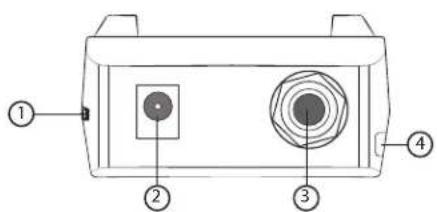
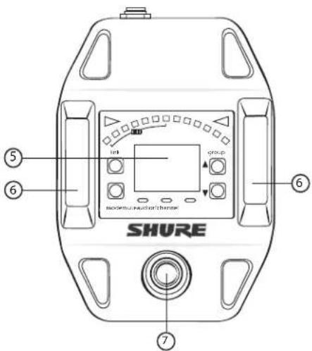
Guitar Pedal Receiver Overview
① Power Switch
Turns power on or off.
② DC Power Connector
Connect DC power supply (9 to 15 V DC, 250 mA min., 400 mA max.)
Note: Compatible with positive tip or negative tip power supplies.
③ Audio Output Jack
Connect to amplifier or mixer.
Note: If using multiple effects pedals, place the receiver pedal first in the signal chain.
④ USB Port
⑤ Display
Displays receiver and tuner settings.
⑥ Antenna
Carries wireless signal, 2 per receiver.
⑦ Footswitch
Press to select receiver or tuner mode.
Display Screen, Indicators, and Controls
The controls and display offer specific functionality depending on which mode is selected:
Receiver Mode
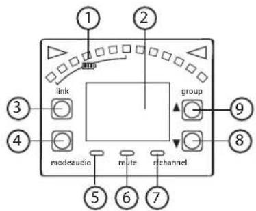
① Transmitter Battery Meter
Illuminated segments indicate remaining battery life
② Display
Group
Channel
LK (controls locked)
UN (controls unlocked)
-- (frequency not available)
③ Link Button
Press to manually link receiver to a transmitter or to activate the remote ID function
④ Mode Button
Press to enable audio gain adjustment. Use ▲▼ buttons to adjust gain.
⑤ Audio LED
Illumination corresponds to audio level. Rapid flashing indicates audio clipping.
⑥ Mute LED
Illuminates when audio output is muted.
⑦ RF LED
• ON = Linked transmitter is on
- Flashing = Searching for transmitter
• OFF = Linked transmitter off or transmitter unlinked
⑧ Channel Button
Press to select and edit channel
⑨ Group Button
Press to select and edit group
Tuner Mode
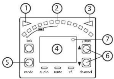
① Flat Indicator
Illuminates when note is flat.
② Tuning Bar Display
LEDs illuminate to indicate tuning deviation.
③ Sharp Indicator
Illuminates when note is sharp.
④ Note Display
Displays the name of the note or (--) if the tuner is idle.
⑤ Mode Button
Press to enter tuner menu settings.
⑥ Arrow Buttons
Use ▲▼ buttons to select and edit menu settings.
⑦ Frequency Detuned/Reference Pitch Offset indicator
A dot is displayed when the tuning or pitch has be set to a non-standard value.
Note: Non-standard turning or pitch settings scroll across the receiver display during power-up.
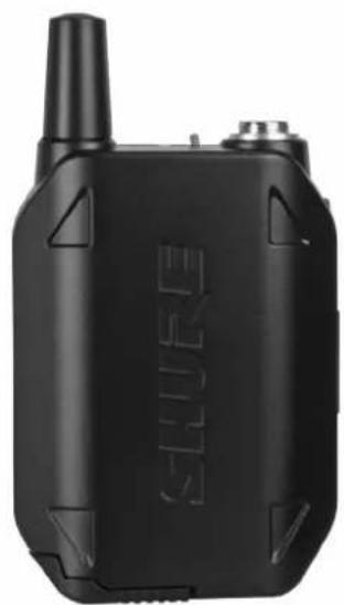
Bodypack Transmitter
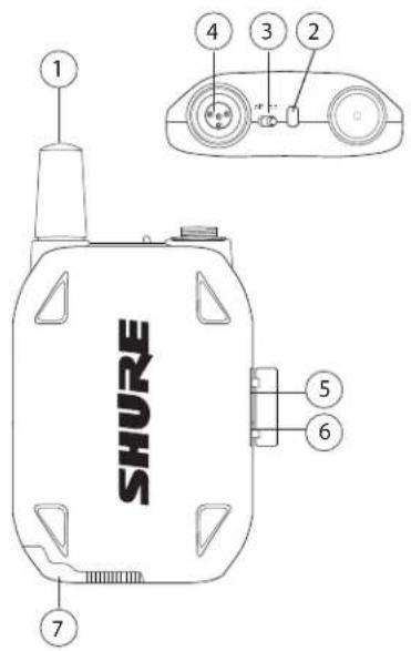
① Antenna
Carries wireless signal.
② Status LED
Indicates transmitter status.
③ Power Switch
Turns the transmitter on/off.
④ TA4M Input Jack
Connects to a 4-Pin mini connector (TA4F) microphone or instrument cable.
⑤ Micro USB Charging Port
Connection for battery charging.
⑥ Link Button
- Press and hold within 5 seconds of power-on to manually link with receiver
- Press momentarily to activate Remote ID function to a linked receiver
⑦ Battery Compartment
Holds Shure rechargeable battery.
Transmitter Status LED
LED is green during normal operation.
LED color or flashing indicates a change in transmitter status as shown in the following table:
| Color State Status | ||
| Green Flashing (slow) | transmitter attempting relink with receiver | |
| unlinked transmitter searching for receiver | ||
| indicates locked transmitter when power switch is pressed | ||
| Red On battery life < 1 hour | ||
| Red/ Green | Flashing remote ID active | |
| Amber Flashing battery error, replace battery | ||
Wearing the Bodypack Transmitter
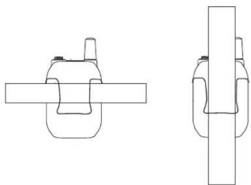
Clip the transmitter to a belt or slide a guitar strap through the transmitter clip as shown.
For best results, the belt should be pressed against the base of the clip.
natural_image
Technical line drawing of two mechanical components with no visible text or symbolsBatteries and Charging
GLX-D transmitters are powered by Shure SB902 lithium-ion rechargeable batteries. Advanced battery chemistry maximizes runtimes with zero memory effects, eliminating the need to discharge batteries prior to charging.
When not in use, recommended battery storage temperature is 10^ C ( 50^ F) to 25^ C ( 77^ F).
Note: The transmitter will not pass RF or audio signals when connected to the charging cable.
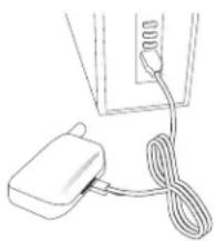
The following battery charging options are available:
-
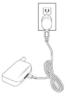
Plug the charging cable into the charging port on the transmitter.
-
Plug the charging cable into an AC power source.
natural_image
Simple line drawing of a plug connected to a cable with a power outlet (no text or symbols)Charging from a USB PortCharging from an AC Power Source
-
Plug the USB charging cable into the charging port on the transmitter.
-
Plug the cable into a standard USB port.
natural_image
Simple line drawing of a plug connected to a cord with a cable (no text or symbols)LED Status During Charging
The following LED states indicate battery status when the transmitter is connected to a charger:
- Green = charging complete
• Green Flashing = battery charge > 90% - Red = battery charging
- Amber Flashing = battery error, replace battery
Charging Times and Transmitter Runtimes
Use the following table to determine approximate battery runtime based on the duration of charging time. Times shown are in hours and minutes.
Note: Batteries charge faster when using an AC powered charger versus a USB connection.
| AC Power Source Charging | USB Connection Charging | Transmitter Runtime |
| 0:15 0:30 up to 1:30 | ||
| 0:30 1:00 up to 3:00 | ||
| 1:00 2:00 up to 6:00 | ||
| 3:00 4:00 up to 16:00* |
*Storage time or excessive heat will reduce maximum runtime.
Note: GLX-D transmitters automatically power-off after approximately 1 hour to conserve battery life if the signal from a linked receiver is not detected.
Installing Transmitter Batteries
Bodypack Transmitter
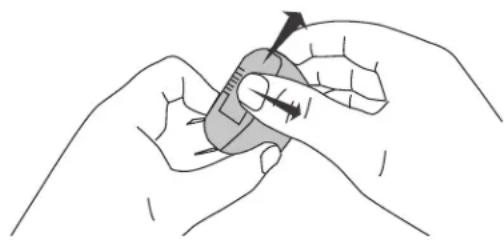
- Move the locking lever to the open position and slide the battery door open.
- Place the battery into the transmitter.
- Close the battery door and slide door to engage the latch.
natural_image
Illustration of a finger pressing a small object with an arrow indicating force (no text or symbols)Transmitter Battery Meter
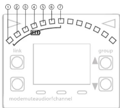
The number of segments illuminated on the meter indicates the remaining battery life for a linked transmitter:
① = > 30 min
② = > 2 hours
③ = > 4 hours
④ = > 6 hours
⑤ = > 8 hours
⑥ = > 10 hours
⑦ = > 12 hours
Note: The LEDs will cycle on/off while battery life is being calculated.
Multiple Receiver Systems
If several channels of wireless audio are needed, up to 8 GLX-D receivers can operate simultaneously in the 2.4 GHz spectrum. For ease of set up, available frequencies are divided into three groups based on the number of receivers supported.
All receivers in the system must be set to the same group. To select a group, determine the total number of receivers in the system (channel count), and then select the appropriate group.
Note: To maximize the number of receivers on-air, Group 3 does not offer backup frequencies. Group 3 should only be used in controlled Wi-Fi environments to prevent interference from unexpected Wi-Fi devices.
| Group Channel Count | Backup Frequencies Available? | Notes |
| 1 Up to 4 Yes Initial Factory Setting. | ||
| 2 Up to 5 Yes Best Group to use if you experience interference. | ||
| 3 Up to 8 No Only use Group 3 in controlled Wi-Fi environments because there are no backup frequencies to avoid interference. |
Note: If you experience interference, reduce transmitter to receiver distance and set all GLX-D systems to group 2, which is the most robust wireless group.
See "Tips to Improve Wireless System Performance" section for additional information.
Setting Up Receivers and Transmitters
Note: Before beginning, turn off all receivers and transmitters. Turn on and set up each receiver/transmitter pair individually to prevent cross-linking.
- Turn on the first receiver.
- Press and hold the group button to select a group (if necessary) or if the group is already set, press the channel button to scan for the best available channel.
- Turn on the first transmitter. The blue rf LED will illuminate when a link is established.
Repeat steps 1-3 for each additional receiver and transmitter. Remember to set each receiver to the same group.
Note: Dashes appearing on the group and channel display during a channel scan indicate that frequencies are not available in the selected group. Choose a group that supports more receivers and repeat the set up steps.
Manually Selecting a Group and Channel
Specific groups and channels can be assigned to the receiver instead of using the automatic scan function.
Note: Group 3 should only be used in controlled Wi-Fi environments to prevent interference from unexpected Wi-Fi devices.
Selecting a Group
- Press and hold the group button for 2 seconds until the group display flashes.
- Press the group button to scroll through the available groups.
- The receiver will automatically save the selected group.
Selecting a Channel
- Press and hold the channel button for 2 seconds until the channel display flashes.
- Press the channel button to scroll through the available channels.
- The receiver will automatically save the selected channel.
Note: A double dash symbol-- displayed on the receiver screen during a channel scan indicates that there are no available channels within the selected group. Choose a group with more channels and repeat set up steps.
Manually Linking a Transmitter to a Receiver
Use the manual linking option to change the transmitter linked to a receiver. A common use for manual linking is changing the linked transmitter from a bodypack type to a handheld type.
- Turn on the transmitter: Within 5 seconds, press and hold the LINK button until the transmitter LED begins to flash green.
- Press and hold the link button on the receiver: The blue rf LED will flash, and then remain on when the link has been established.
- Test the audio to verify the link and adjust the gain if necessary.
2.4 GHz Spectrum Overview
GLX-D operates within the 2.4GHz ISM band which is utilized by Wi-Fi, Bluetooth, and other wireless devices. The benefit of 2.4GHz is that it's a global band that can be used anywhere in the world, license free.
Overcoming the Challenges of 2.4GHz
The challenge of 2.4GHz is that Wi-Fi traffic can be unpredictable. GLX-D meets these challenges in the following ways:
- Prioritizes and transmits on the best 3 frequencies per channel (choosing from a pool of 6 frequencies across the 2.4GHz band)
- Repeats the most important information such that one frequency can be taken out entirely without audio interruption
- Continuously scans during usage to rank all frequencies (both current and backup frequencies)
- Seamlessly moves away from interference to backup frequencies without audio interruption
Coexisting with Wi-Fi
GLX-D avoids continuous Wi-Fi traffic by scanning the entire 2.4GHz environment and selecting the 3 best frequencies to transmit on. The result of this is reliable performance for your GLX-D wireless system as well as avoiding Wi-Fi transmissions which may be important as well.
"Bursting" Wi-Fi is harder to detect as it is periodic; however, because GLX-D repeats the most important information, even bursts at very high-levels don't have an effect on your audio performance.
Challenging Wireless Environments
Some environments are more difficult than others for 2.4 GHz wireless system performance. The simplest solution in many cases is to reduce the transmitter to receiver distance such as placing the receivers on the stage with a clear line of sight.
Challenging environments include:
- Outdoors
- Very high ceilings
- 3 or more GLX-D receivers in use
• Strong Wi-Fi presence
• Non-Shure 2.4 GHz systems in use
Tips to Improve Wireless System Performance
If you encounter interference or dropouts, try the following suggestions:
- Scan for the best available channel (press the channel button)
- Reposition the receiver so there is nothing obstructing a line of sight to the transmitter (including the audience)
- Keep the transmitter and receiver more than 2 meters (6 feet) apart
- Keep transmitter to receiver distance within 60 meters (200 feet) - place receivers on-stage within line of sight if possible
- Remove or relocate nearby sources of wireless interference, such as Wi-Fi devices or hotspots, cell phones, two-way radios, computers, media players, and digital signal processors
-
Disable non-essential Wi-Fi/bluetooth devices and avoid heavy Wi-Fi traffic activities such as downloading large files or viewing a movie.
-
Locate GLX-D receivers away from non-Shure 2.4 GHz receivers
- Avoid placing transmitter and receiver where metal or other dense materials may be present
- Keep transmitters more than 2 meters (6 feet) apart Note: GLX-D transmitters closer than 6 inches (15 cm) to other non-GLX-D transmitters may cause audible noise in that transmitter
- During sound check, mark trouble spots and ask presenters or performers to avoid those areas
2.4 GHz Frequency Tables
The following tables list receiver channels, frequencies, and latency for each group:
Group 1: Channels 1-4 (latency = 4.0 ms)
| Group/Channel Frequencies | |||
| 1/1 2424 2425 2442 | |||
| 2443 | 2462 | 2464 | |
| 1/2 2418 2419 2448 | |||
| 2450 | 2469 | 2471 | |
| 1/3 2411 2413 2430 | |||
| 2431 | 2476 | 2477 | |
| 1/4 2405 2406 2436 | |||
| 2437 | 2455 | 2457 | |
Group 2: Channels 1-5 (latency = 7.3 ms)
| Group/Channel Frequencies | |||
| 2/1 2423 2424 2443 | |||
| 2444 2473 2474 | |||
| 2/2 2404 2405 2426 | |||
| 2427 2456 2457 | |||
| 2/3 2410 2411 2431 | |||
| 2432 2448 2449 | |||
| 2/4 2417 2418 2451 | |||
| 2452 2468 2469 | |||
| 2/5 2437 2438 2462 | |||
| 2463 2477 2478 | |||
Group 3: Channels 1-8 (latency = 7.3 ms)
| Group/Channel Frequencies | |||
| 3/1 2415 2416 2443 | |||
| 3/2 2422 2423 2439 | |||
| 3/3 2426 2427 2457 | |||
| 3/4 2447 2448 2468 | |||
| 3/5 2409 2451 2452 | |||
| 3/6 2431 2462 2463 | |||
| 3/7 2404 2473 2474 | |||
| 3/8 2435 2477 2478 | |||
Receiver Operation
Audio Gain Adjustment
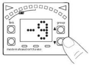
Transmitter gain has an adjustment range from -20 dB to +40 dB, in 1 dB increments.
Tip: Try the 0 dB (unity gain) setting as a starting point, and then make gain adjustments if necessary.
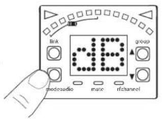
- Press and hold the mode button on the receiver until dB appears on the display.
- Press the up/down arrows to adjust the gain. For faster adjustments, press and hold the buttons.
Note: The intensity of the green audio LED corresponds to the audio level. Rapid flashing indicates audio clipping. Reduce the gain to remove the overload.
Locking and Unlocking the Controls
The controls of the receiver and transmitter can be locked to prevent accidental or unauthorized changes to settings.
The following parameters are not affected by locking the controls:
- Lock status is not changed by power cycles
- Tuner functionality and editing remains available
• The receiver power switch does not lock
Locking the Receiver Controls
Simultaneously press and hold the group and channel buttons to lock or unlock the receiver.
- LK is displayed if a locked control is pressed
- UN is displayed momentarily to confirm the unlock command
Locking the Transmitter Power Switch
Starting with the transmitter set to off, press and hold the LINK button while turning on the transmitter. Repeat sequence to unlock.
Note: The transmitter status LED will flash red/green if a locked switch is set to the off position.
Remote ID
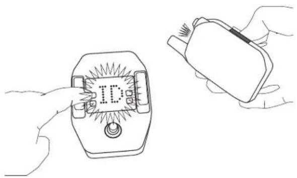
Use the Remote ID feature to identify linked transmitter and receiver pairs. When Remote ID is active, the receiver LCD will blink and display ID. The status LED of the corresponding transmitter will alternately flash red and green for approximately 45 seconds.
To activate Remote ID:
- Momentarily press the link button on the transmitter or receiver.
- The display of the linked receiver will blink and show ID and the status LED on the linked transmitter will flash red/green.
- To exit Remote ID mode, momentarily press the link button or allow the function to timeout.
natural_image
Line drawing of two hands holding a device with a labeled 'ID' and a cable (no text or symbols on the device itself)Tuner Menu
Enter tuner mode by pressing the footswitch.
In tuner mode, the controls will only affect tuner functions, RF and audio settings are not affected.
Note: The audio signal does not pass through the tuner, eliminating the need for bypass switches commonly found on wired tuners.
Tuner Options
• Indicator: Needle or Strobe
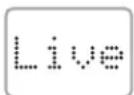
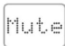
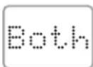
• Output: Live, Mute, or Both
- Display Brightness
- Detune
- Sharps and Flats
- Reference Pitch
Selecting and Editing Tuner Menu Settings
Use the following buttons to select and edit the tuner menu settings:
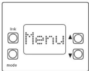
- Use the mode button access the menu and to scroll between menu settings
- Use the Use ▲▼ buttons to change a menu parameter
- Use the footswitch to enter and save parameter changes
Indicator: Needle or Strobe
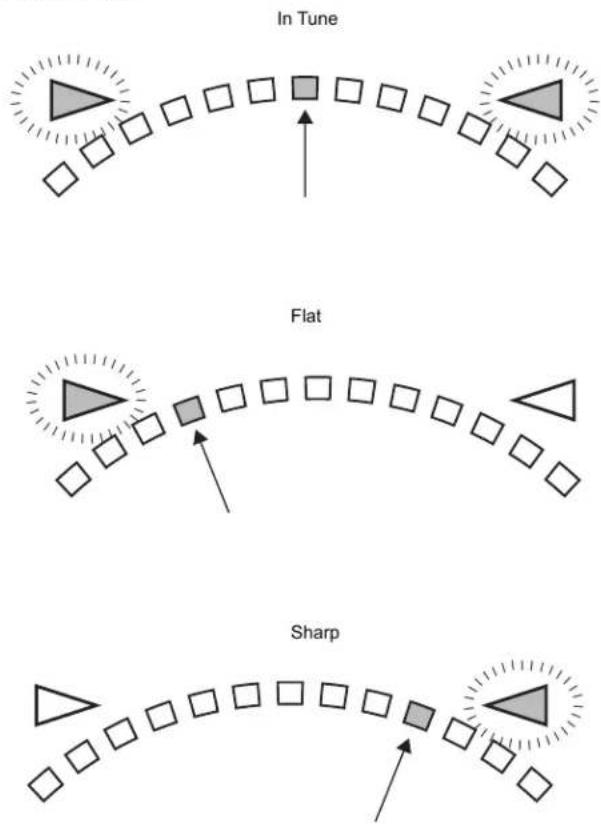
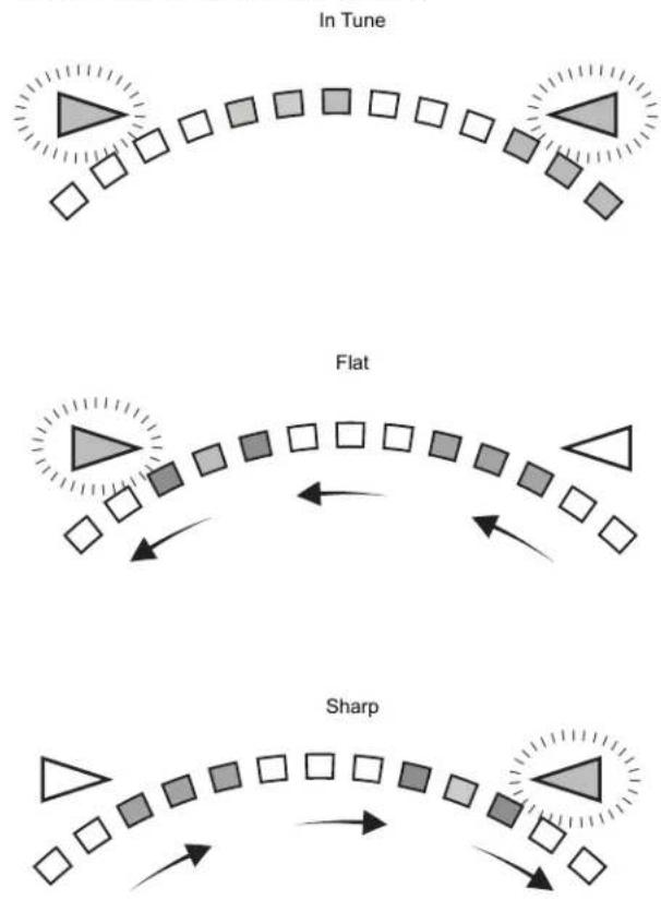
The tuner indicator can be set to display a needle style or strobe style.
Needle
A single LED will illuminate on the tuning bar to indicate sharp or flat. The green center LED will illuminate when the note is in tune.
Strobe
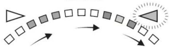
A sequence of three LEDs will travel across the tuning bar in the direction of sharp or flat. The LEDs will remain stationary when the note is in tune.

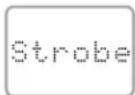
Note: Indicator and Output settings are displayed in a scroll from left to right.
Choosing Live or Mute Audio Output
The following modes are available to set the audio output to Live or Mute when the footswitch is pressed in tuner mode.
Note: Text for the output settings are displayed in a scroll from left to right.
| Mode Footswitch Function | |
| Live | Receiver Display (audio Live) Tuner Display (audio Live) |
| Mute | Receiver Display (audio Live) Tuner Display (audio Mute) |
| Both | Tuner Display (audio Mute) Tuner Display (audio Live)* |
*Note: In Both mode, the pedal powers up in Receiver Display. Press the footswitch to enter tuner mode.
Display Brightness
The receiver has a built-in light sensor to automatically adjust the display brightness.
To manually adjust the brightness choose one of the following settings:

*A = automatic

*1 = low

*2 = medium

*3 = high
Detune
The tuner can be set to display standard tuning for instruments that have been detuned up sharp or flat in the following increments:
- Up to 5 steps sharp (#1-#2-#3-#4-#5)
- Up to 6 steps flat (b6-b5-b4-b3-b2-b1)
The notation for standard tuning is b0
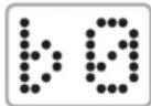
b0 = Standard Tuning
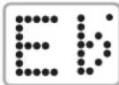
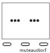
Example of note displayed in Detune mode
* dot appears on the display as a reminder that the pedal is detuned.
Sharps and Flats
Adds sharp or flat symbols to the display of non-natural notes.
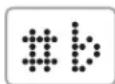
Sharps and Flats
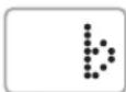
Flats only
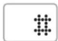
Sharps only
Reference Pitch
The reference pitch can be offset from standard A440 in a range of 432 Hz to 447 Hz in 1 Hz increments.
When adjusting the pitch, the last 2 digits of the value will be displayed. For example, "32" would appear on the display when the pitch has been set to 432 Hz.

natural_image
Pure horizontal line with tick marks, no text or symbols presentA440 447 Hz432 Hz
A dot appears on the display as a reminder that the reference pitch has been offset.
Using the Tuner
- Press the footswitch to enter tuner mode.
- Play each note individually. The display shows the name of the note.
- Adjust tuning until both indicators illuminate and the needle or strobe indicate that tuning is correct.
Needle Mode
Both tuning indicators and the center green segment will illuminate when the note is in tune.
flowchart
graph TD
    A["In Tune"] --> B["Flat"]
    B --> C["Sharp"]
    style A fill:#999,stroke:#333
    style B fill:#ccc,stroke:#333
    style C fill:#fff,stroke:#333
Strobe Mode
Both tuning indicators will illuminate and the strobe segments will remain stationary when the note is in tune.
flowchart
graph TD
    A["Square in"] --> B["Square"]
    B --> C["Square"]
    C --> D["Square"]
    D --> E["Square"]
    E --> F["Square"]
    F --> G["Square"]
    G --> H["Square"]
    H --> I["Square"]
    I --> J["Square"]
    J --> K["Square"]
    K --> L["Square"]
    L --> M["Square"]
    M --> N["Square"]
    N --> O["Square"]
    O --> P["Square"]
    P --> Q["Square"]
    Q --> R["Square"]
    R --> S["Square"]
    S --> T["Square"]
    T --> U["Square"]
    U --> V["Square"]
    V --> W["Square"]
    W --> X["Square"]
    X --> Y["Square"]
    Y --> Z["Square"]
    Z --> AA["Square"]
    AA --> AB["Square"]
    AB --> AC["Square"]
    AC --> AD["Square"]
    AD --> AE["Square"]
    AE --> AF["Square"]
    AF --> AG["Square"]
    AG --> AH["Square"]
    AH --> AI["Square"]
    AI --> AJ["Square"]
    AJ --> AK["Square"]
    AK --> AL["Square"]
    AL --> AM["Square"]
    AM --> AN["Square"]
    AN --> AO["Square"]
    AO --> AP["Square"]
    AP --> AQ["Square"]
    AQ --> AR["Square"]
    AR --> AS["Square"]
Troubleshooting
| Issue Indicator Status Solution | ||
| No sound or faint sound | Receiver RF LED on | ·Verify all sound system connections or adjust gain as needed (see Adjusting Gain)·Verify that the receiver is connected to mixer/amplifier |
| Receiver RF LED off | ·Turn on transmitter·Make sure the batteries are installed correctly·Link transmitter and receiver (see Linking topic)·Charge or change transmitter battery | |
| Receiver display off · Make sure AC adapter is securely plugged into electrical outlet.·Make sure receiver is powered on. | ||
| Transmitter indicator LED flashing red | Charge or change transmitter battery | |
| Transmitter plugged into charger. | Disconnect transmitter from charger. | |
| Audio artifacts or dropouts | r-f LED flickering or off | ·Change receiver and transmitter to a different group and/or channel.·Identify nearby sources of interference (cell phones, Wi-Fi access points, signal processor, etc...) and shutdown or remove source.·Charge or changer transmitter battery·Ensure that receiver and transmitter are positioned within system parameters·System must be set up within recommended range and receiver kept away from metallic surfaces.·Transmitter must be used in line of sight from receiver for optimal sound |
| Distortion | Receiver audio LED blinks rapidly | Reduce transmitter gain (see Gain Adjustment). |
| Sound level variations when switching to different sources | N/A Adjust transmitter gain as necessary (see Gain Adjustment). | |
| Receiver/transmitter won't turn off Transmitter | LED flashing rapidly | Controls locked. See Locking and Unlocking Controls. |
| Receiver gain control cannot be adjusted N/A | Check transmitter. Transmitter must be on to enable gain changes. | |
| Receiver controls cannot be adjusted | LK shown on receiver display when buttons are pressed | Controls locked. See Locking and Unlocking Controls. |
| Transmitter ID function does not respond. Transmitter LED flashes green 3 times | Controls locked. See Locking and Unlocking Controls. | |
| Transmitter information does not appear on the Receiver LCD | N/A Linked transmitter is off or the receiver is not linked to a transmitter. | |
| Transmitter powers off after 1 hour. Transmitter status LED off | GLX-D transmitters automatically power-off after 1 hour to conserve battery life if the signal from a linked receiver is not detected. Make sure that linked receiver is turned on. | |
Resetting Components
Use the reset function if it is necessary to restore the transmitter or receiver to their factory settings.
Resetting the Receiver
Restores the receiver to the following factory settings:
- Gain level = default
- Controls = unlocked
Press and hold the link button while turning on the receiver power until the LCD displays RE.
Note: When reset is complete, the receiver will automatically initiate linking to search for a transmitter. Press and hold the transmitter link button within five seconds of powering-on to complete the link.
Resetting the Transmitter
Restores the transmitter to the following factory settings:
- Controls = unlocked
Press and hold the transmitter link button while turning on the transmitter until power LED goes off.
When the link button is released, the transmitter will automatically initiate linking to find an available receiver. Press the link button on an available receiver to relink.
Specifications
Tuning Bandwidth
2400–2483.5 MHz
Working Range
60 m (200 ft) typical
Note: Actual range depends on RF signal absorption, reflection and interference.
Transmit Mode
Frequency Hopping
Audio Frequency Response
20 Hz - 20 kHz
Dynamic Range
120 dB, A-weighted
RF Sensitivity
-88 dBm, typical
Total Harmonic Distortion
0.2%, typical
RF Output Power
10 mW E.I.R.P. max
Operating Temperature Range
-18°C (0°F) to 57°C (135°F)
Note: Battery characteristics may limit this range.
Storage Temperature Range
-29°C (-20°F) to 74°C (165°F)
Polarity
Positive voltage applied to the tip of the guitar cable phone plug produces positive voltage at the tip of the high impedance 14 -inch output.
Battery Life
Up to 16 hours
GLXD1
Dimensions
90 x 65 x 23 mm(3.56 x 2.54 x 0.90in.), H x W x D (without antenna)
Power Requirements
3.7 V Rechargeable Li-Ion
Housing
Cast Metal, Black Powdercoat
Input Impedance
900 kΩ
RF Output Power
10 mW E.I.R.P. max
Transmitter Input
Connector
4-Pin male mini connector (TA4M)
Configuration
Unbalanced
Maximum Input Level
1 kHz at 1% THD
+8.4 dBV (7.5 Vp-p)
Antenna Type
Internal Monopole
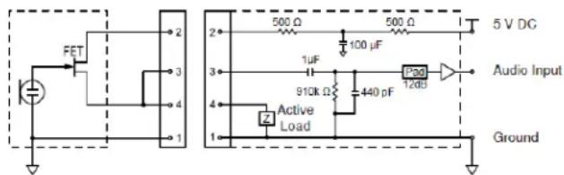
Pin Assignments
TA4M
| 1 | ground (cable shield) |
| 2 | + 5 V Bias |
| 3 | audio |
| 4 | Tied through active load to ground (On instrument adapter cable, pin 4 floats) |
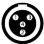
TA4M Connector
GLXD6
Dimensions
46 x 95 x 133 mm (1.8 x 3.7 x 5.2 in.), H x W x D
Weight
504 g (17.8 oz.)
Housing
Cast Metal, Black Powdercoat
Power Requirements
9 to 15 V DC, 250 mA min., 400 mA max.
Compatible with positive tip or negative tip power supplies.
Spurious Rejection
35 dB, typical
Gain Adjustment Range
-20 to 40 dB in 1 dB steps
Configuration
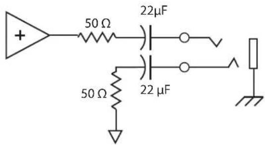
| 6.35 mm (1/4") output | Impedance balanced |
Impedance
| 6.35 mm (1/4") output | 100 Ω(50 Ω, Unbalanced) |
Maximum Audio Output Level
| 6.35 mm (1/4") connec-tor (into 3 kΩ load) | +8.5 dBV |
Pin Assignments
| 6.35 mm (1/4") connector | Tip=audio, Ring=no audio, Sleeve=ground |
Receiver Antenna Input
Impedance
50 Ω
Antenna Type
PIFA antennas
Maximum Input Level
-20 dBm
Output Connections
Certifications
This device complies with part 15 of the FCC Rules. Operation is subject to the following two conditions: (1) This device may not cause harmful interference, and (2) this device must accept any interference received, including interference that may cause undesired operation.
This wireless system operates in the globally available ISM band 2400 MHz to 2483.5 MHz. The operation does not require a user license.
Meets requirements of the following standards: EN 300 328, EN 301 489 Parts 1 and 9, EN60065.
Meets essential requirements of the following European Directives:
• R&TTE Directive 99/5/EC
• WEEE Directive 2002/96/EC, as amended by 2008/34/EC
• RoHS Directive 2002/95/EC, as amended by 2008/35/EC
Note: Please follow your regional recycling scheme for batteries and electronic waste
Certified by IC in Canada under RSS-210 and RSS-GEN.
IC: 616A-GLXD1, 616A-GLXD6
Certified under FCC Part 15.
This device complies with Industry Canada licence-exempt RSS standard(s). Operation of this device is subject to the following two conditions: (1) this device may not cause interference, and (2) this device must accept any interference, including interference that may cause undesired operation of the device.
The CE Declaration of Conformity can be obtained from Shure Incorporated or any of its European representatives. For contact information please visit www.shure.com
The CE Declaration of Conformity can be obtained from: www.shure.com/europe/compliance
Authorized European representative:
Shure Europe GmbH
Headquarters Europe, Middle East & Africa
Department: EMEA Approval
Jakob-Dieffenbacher-Str. 12
75031 Eppingen, Germany
Phone: 49-7262-92 49 0
Fax: 49-7262-92 49 11 4
Email: EMEAsupport@shure.de
Information to the user
This equipment has been tested and found to comply with the limits for a Class B digital device, pursuant to Part 15 of the FCC Rules. These limits are designed to provide reasonable protection against harmful interference in a residential installation. This equipment generates uses and can radiate radio frequency energy and, if not installed and used in accordance with the instructions, may cause harmful interference to radio communications. However, there is no guarantee that interference will not occur in a particular installation. If this equipment does cause harmful interference to radio or television reception, which can be determined by turning the equipment off and on, the user is encouraged to try to correct the interference by one or more of the following measures:
- Reorient or relocate the receiving antenna.
- Increase the separation between the equipment and the receiver.
- Connect the equipment to an outlet on a circuit different from that to which the receiver is connected.
- Consult the dealer or an experienced radio/TV technician for help.
Étape ①
⑥ Antenne
natural_image
Technical line drawing of two mechanical components with no visible text or symbolsAccus et charge
natural_image
Line drawing of a plug connected to a cable with a power outlet (no text or symbols)natural_image
Line drawing of a small electronic device connected to a cable with a plug (no text or symbols)natural_image
Illustration of a hand holding a small object with an arrow indicating motion (no text or symbols)natural_image
Line drawing of two hands holding a device with a labeled 'ID' and a cable (no text or symbols on the device itself)Menu de l'accordeur
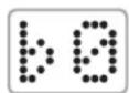
b0 = Accordage standard
flowchart
graph TD
    A["Square"] --> B["Arrow"]
    C["Triangle"] --> D["Arrow"]
    E["Square"] --> F["Arrow"]
    G["Square"] --> H["Arrow"]
    I["Square"] --> J["Arrow"]
    K["Square"] --> L["Arrow"]
    M["Square"] --> N["Arrow"]
Note trop haute
flowchart
graph TD
    A["Start"] --> B{Decision}
    B -->|Yes| C["Process Step"]
    B -->|No| D["End"]
Dépannage
Service : Homologation EMA
Jakob-Dieffenbacher-Str. 12
Schritt ①
⑥ Antenne
natural_image
Technical line drawing of two mechanical components with no visible text or symbolsnatural_image
Simple line drawing of a plug connected to a cable with a power outlet (no text or symbols)natural_image
Simple line drawing of a plug connected to a cable with a plug inserted (no text or symbols)natural_image
Illustration of a hand holding a finger with an arrow indicating force or movement (no text or symbols)Senderakku-Anzeige
natural_image
Line drawing of two hands holding a device with a labeled 'ID' and a separate device (no text or symbols on the device itself)Stimmgerät-Menü
60 m (200 ft) typical
Note: Actual range depends on RF signal absorption, reflection and interference.
Transmit Mode
Frequency Hopping
Audio Frequency Response
20 Hz - 20 kHz
Dynamic Range
120 dB, A-weighted
RF Sensitivity
-88 dBm, typical
Total Harmonic Distortion
0.2%, typical
RF Output Power
10 mW E.I.R.P. max
Operating Temperature Range
-18°C (0°F) to 57°C (135°F)
Note: Battery characteristics may limit this range.
Storage Temperature Range
-29°C (-20°F) to 74°C (165°F)
Polarity
Positive voltage applied to the tip of the guitar cable phone plug produces positive voltage at the tip of the high impedance 14 -inch output.
Battery Life
Up to 16 hours
GLXD1
Dimensions
90 x 65 x 23 mm(3.56 x 2.54 x 0.90in.), H x W x D (without antenna)
Power Requirements
3.7 V Rechargeable Li-Ion
Housing
Cast Metal, Black Powdercoat
Input Impedance
900 kΩ
RF Output Power
10 mW E.I.R.P. max
Transmitter Input
Connector
4-Pin male mini connector (TA4M)
Configuration
Unbalanced
Maximum Input Level
1 kHz at 1% THD
+8.4 dBV (7.5 Vp-p)
Antenna Type
Internal Monopole
Pin Assignments
TA4M
| 1 | ground (cable shield) |
| 2 | +5 V Bias |
| 3 | audio |
| 4 | Tied through active load to ground (On instrument adapter cable, pin 4 floats) |
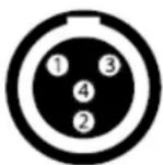
TA4M Connector
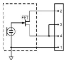
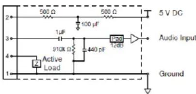
GLXD6
Dimensions
46 x 95 x 133 mm (1.8 x 3.7 x 5.2 in.), H x W x D
Weight
504 g (17.8 oz.)
Housing
Cast Metal, Black Powdercoat
Power Requirements
9 to 15 V DC, 250 mA min., 400 mA max.
Compatible with positive tip or negative tip power supplies.
Spurious Rejection
35 dB, typical
Gain Adjustment Range
-20 to 40 dB in 1 dB steps
Configuration
| 6.35 mm (1/4") output | Impedance balanced |
Impedance
| 6.35 mm (1/4") output | 100 Ω(50 Ω, Unbalanced) |
Maximum Audio Output Level
| 6.35 mm (1/4") connec-tor (into 3 kΩ load) | +8.5 dBV |
Pin Assignments
| 6.35 mm (1/4") connector | Tip=audio, Ring=no audio, Sleeve=ground |
Receiver Antenna Input
Impedance
50 Ω
Antenna Type
PIFA antennas
Maximum Input Level
-20 dBm
Output Connections
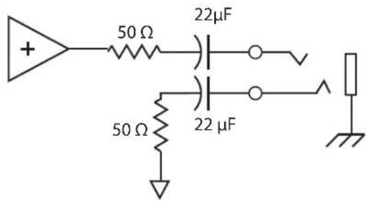
Zulassungen
Paso ①
⑥ Antena
natural_image
Technical line drawing of two mechanical components with no visible text or symbolsBaterías y carga
natural_image
Simple line drawing of a plug connected to a power outlet cable (no text or symbols)Estado del LED durante la carga
natural_image
Line drawing of a small electronic device connected to a cable with a plug (no text or symbols)natural_image
Illustration of a hand holding a finger with an arrow indicating force or movement (no text or symbols)natural_image
Line drawing of two hands holding a device with a labeled 'ID' and a cable (no text or symbols on the device itself)Menú de afinador
Etapa ①
⑥ Antena
③ Interruptor Liga/Desliga
Liga e desliga o transmissor.
natural_image
Technical line drawing of two mechanical components with no visible text or symbolsPilhas e Carga
natural_image
Simple line drawing of a plug connected to a power outlet cable (no text or symbols)natural_image
Simple line drawing of a plug connected to a cable with a plug inserted (no text or symbols)natural_image
Illustration of hands performing a finger manipulation or tooling task (no text or symbols present)natural_image
Line drawing of two hands holding a device with a labeled 'ID' and a cable (no text or symbols on the device itself)Menu do Afinador
War ①
⑥ Антенна
① Индикатор бемолей
natural_image
Technical line drawing of two mechanical components with no visible text or symbolsБатарейки и зарядка
natural_image
Line drawing of a plug connected to a power outlet cable (no text or symbols)natural_image
Simple line drawing of a plug connected to a cable, no text or symbols presentnatural_image
Illustration of a hand holding a finger with an arrow indicating force or movement (no text or symbols)natural_image
Line drawing of two hands holding a device with a labeled 'ID' and a cable (no text or symbols on the device itself)Меню тюнера
Passaggio ①
natural_image
Technical line drawing of two mechanical components with no visible text or symbolsPile e carica
natural_image
Line drawing of a plug connected to a cable with a power outlet (no text or symbols)natural_image
Line drawing of a plug connected to a cable with a power outlet (no text or symbols)natural_image
Illustration of a hand holding a small object with a tool, no text or symbols presentnatural_image
Line drawing of two hands holding a device with a labeled 'ID' and a separate device (no text or symbols on the device itself)Menu accordatore
Stap ①
⑥ Antenne
Display, indicatoren en bedieningselementen
natural_image
Technical line drawing of two mechanical components with no visible text or symbolsAccu's en opladen
natural_image
Line drawing of a plug connected to a power outlet cable (no text or symbols)natural_image
Simple line drawing of a plug connected to a cable with a plug inserted into the socket (no text or symbols)natural_image
Illustration of a hand holding a small object with an arrow indicating motion (no text or symbols)Accumeter zender
Bedieningselementen vergrendelen en ontgrendelen
natural_image
Line drawing of two hands holding a device with a labeled 'ID' and a cable (no text or symbols on the device itself)Stemapparaatmenu
Indicator: Naald of stroboscoop
flowchart
graph TD
    A["Gestemd"] --> B["Arrow to square"]
    B --> C["Arrow to triangle"]
    C --> D["Arrow to square"]
    D --> E["Arrow to square"]
    E --> F["Arrow to square"]
    F --> G["Arrow to square"]
    G --> H["Arrow to square"]
    H --> I["Arrow to square"]
    I --> J["Arrow to square"]
    J --> K["Arrow to square"]
    K --> L["Arrow to square"]
    L --> M["Arrow to square"]
    M --> N["Arrow to square"]
    N --> O["Arrow to square"]
    O --> P["Arrow to square"]
    P --> Q["Arrow to square"]
    Q --> R["Arrow to square"]
    R --> S["Arrow to square"]
    S --> T["Arrow to square"]
    T --> U["Arrow to square"]
    U --> V["Arrow to square"]
    V --> W["Arrow to square"]
    W --> X["Arrow to square"]
    X --> Y["Arrow to square"]
    Y --> Z["Arrow to square"]
    Z --> AA["Arrow to square"]
    AA --> AB["Arrow to square"]
    AB --> AC["Arrow to square"]
    AC --> AD["Arrow to square"]
    AD --> AE["Arrow to square"]
    AE --> AF["Arrow to square"]
    AF --> AG["Arrow to square"]
    AG --> AH["Arrow to square"]
    AH --> AI["Arrow to square"]
    AI --> AJ["Arrow to square"]
    AJ --> AK["Arrow to square"]
    AK --> AL["Arrow to square"]
    AL --> AM["Arrow to square"]
    AM --> AN["Arrow to square"]
    AN --> AO["Arrow to square"]
    AO --> AP["Arrow to square"]
    AP --> AQ["Arrow to square"]
    AQ --> AR["Arrow to square"]
    AR --> AS["Arrow to square"]
    AS --> AT["Arrow to square"]
    AT --> AU["Arrow to square"]
    AU --> AV["Arrow to square"]
    AV --> AW["Arrow to square"]
    AW --> AX["Arrow to square"]
Probleemoplossing
4-pens miniconnector, mannetje (TA4M)
Configuratie
Ongebalanceerd
Maximaal ingangsniveau
1 kHz bij 1% THD
+8,4 dBV (7,5 Vp-p)
Antennetype
Interne monopool
Pentoewijzingen
TA4M
United States, Canada, Latin
America, Caribbean:
Shure Incorporated
5800 West Touhy Avenue
Niles, IL 60714-4608 USA
Phone: 847-600-2000
Fax: 847-600-1212 (USA)
Fax: 847-600-6446
Email: info@shure.com
www.shure.com
©2013 Shure Incorporated
Europe, Middle East, Africa:
Shure Europe GmbH
Jakob-Dieffenbacher-Str. 12,
75031 Eppingen, Germany
Phone: 49-7262-92490
Fax: 49-7262-9249114
22/F, 625 King's Road
North Point, Island East
Hong Kong
Phone: 852-2893-4290
Fax: 852-2893-4055
- GLX-D Wireless System – GLXD6 Guitar Pedal Receiver
- IMPORTANT SAFETY INSTRUCTIONS
- CONSIGNES DE SÉCURITÉ IMPORTANTES
- WARNING
- Note:
- Quick Start
- Step ①
- Step ②
- Step ③
- Step ④
- Guitar Pedal Receiver Overview
- Display Screen, Indicators, and Controls
- Bodypack Transmitter
- Transmitter Status LED
- Wearing the Bodypack Transmitter
- Batteries and Charging
- Charging from a USB PortCharging from an AC Power Source
- LED Status During Charging
- Charging Times and Transmitter Runtimes
- Installing Transmitter Batteries
- Transmitter Battery Meter
- Multiple Receiver Systems
- Setting Up Receivers and Transmitters
- Manually Selecting a Group and Channel
- Selecting a Group
- Selecting a Channel
- Manually Linking a Transmitter to a Receiver
- GHz Spectrum Overview
- Overcoming the Challenges of 2.4GHz
- Coexisting with Wi-Fi
- Challenging Wireless Environments
- Tips to Improve Wireless System Performance
- GHz Frequency Tables
- Receiver Operation
- Audio Gain Adjustment
- Locking and Unlocking the Controls
- Locking the Receiver Controls
- Locking the Transmitter Power Switch
- Remote ID
- To activate Remote ID:
- Tuner Menu
- Tuner Options
- Selecting and Editing Tuner Menu Settings
- Indicator: Needle or Strobe
- Needle
- Strobe
- Choosing Live or Mute Audio Output
- Display Brightness
- Detune
- Sharps and Flats
- Reference Pitch
- Using the Tuner
- Needle Mode
- Strobe Mode
- Resetting Components
- Resetting the Receiver
- Resetting the Transmitter
- Specifications
- Tuning Bandwidth
- Working Range
- Transmit Mode
- Audio Frequency Response
- Dynamic Range
- RF Sensitivity
- Total Harmonic Distortion
- RF Output Power
- Operating Temperature Range
- Storage Temperature Range
- Polarity
- Battery Life
- GLXD1
- Dimensions
- Power Requirements
- Housing
- Input Impedance
- Transmitter Input
- Connector
- Configuration
- Maximum Input Level
- Antenna Type
- Pin Assignments
- GLXD6
- Weight
- Spurious Rejection
- Gain Adjustment Range
- Receiver Antenna Input
- Impedance
- Certifications
- Information to the user
- Étape ①
- Accus et charge
- Menu de l'accordeur
- Dépannage
- Schritt ①
- ⑥ Antenne
- Senderakku-Anzeige
- Stimmgerät-Menü
- Zulassungen
- Paso ①
- Baterías y carga
- Estado del LED durante la carga
- Menú de afinador
- Etapa ①
- Pilhas e Carga
- Menu do Afinador
- War ①
- Батарейки и зарядка
- Меню тюнера
- Passaggio ①
- Pile e carica
- Menu accordatore
- Stap ①
- Display, indicatoren en bedieningselementen
- Accu's en opladen
- Accumeter zender
- Bedieningselementen vergrendelen en ontgrendelen
- Stemapparaatmenu
- Indicator: Naald of stroboscoop
- Probleemoplossing
- Configuratie
- Maximaal ingangsniveau
- Antennetype
- Pentoewijzingen
Brand : SHURE
Model : GLXD16
Category : Wireless audio equipment