
GW96845 - Digital timer switch Gewiss - Free user manual and instructions
Find the device manual for free GW96845 Gewiss in PDF.

| Product type | Digital time switch |
| Brand | Gewiss |
| Model | GW96845 |
| Dimensions (H x W x D) | 45 x 35 x 60 mm |
| Weight | 220 g |
| Supply voltage | 230 V AC (typical) |
| Power consumption | 1 VA |
| Switching power (resistive load) | 16 A / 250 V AC |
| Number of channels | 2 (changeover) |
| Program memory | 70 slots |
| Programming types | Weekly, holiday, astronomical |
| Display | 3-line LCD screen |
| Mounting | On DIN rail |
| Running accuracy | ±0.5 s/day at +20°C |
| Minimum switching time | 1 s |
| Ambient temperature | -10°C to +55°C |
| Protection class | II |
| Backup battery | Lithium CR2032 |
| Sealable | Yes |
| Main functions | Time switching, presence simulation, holiday mode, astronomical, manual override |
| Maintenance | Battery replacement, cleaning with a dry cloth |
| Safety | Disconnect before battery replacement, installation by a qualified electrician |
Frequently Asked Questions - GW96845 Gewiss
User questions about GW96845 Gewiss
0 question about this device. Answer the ones you know or ask your own.
Ask a new question about this device
Download the instructions for your Digital timer switch in PDF format for free! Find your manual GW96845 - Gewiss and take your electronic device back in hand. On this page are published all the documents necessary for the use of your device. GW96845 by Gewiss.
USER MANUAL GW96845 Gewiss
natural_image
Abstract geometric shape with a curved arrow pointing to a small square cutout (no text or symbols)The connection and installation of electrical devices may only be carried out by a qualified electrician.
- Interventions in and changes to the device result in the voiding of the warranty claim.
- Observe your national regulations and the respective safety provisions.
- Minimum diameter of the flexible lines for the terminals: 1 mm ^2 . Maximum diameter: 4 mm ^2 .
- Flexible cables with a cross-section ≤ 1mm^2 should not be attached.
GENERAL INFORMATION
- 70 memory locations
- Date-based programming
- Weekly program * / Holiday program * / Astro program * (Function not available for all products).
- The timer is used for:
– lighting in private homes and commerce - advertising / street lighting / shop window lighting
- controlling devices, motors and pumps
- controlling shutters and blinds
– Presence simulation
- Mounting only on DIN rail
- Suitable for use in dry rooms only!
- Do not install in the vicinity of devices having inductive discharges (motors, transformers, etc.)
INSTALLATION ON DIN RAIL
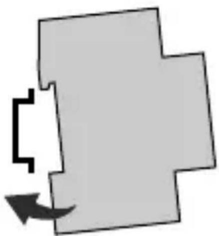
natural_image
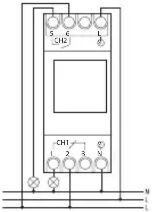
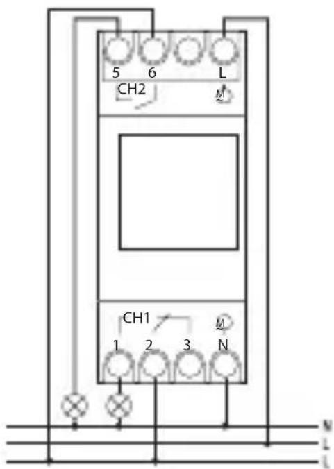
Abstract geometric shape with a black arrow pointing to a white square cutout (no text or symbols)TERMINAL DIAGRAM
CH1 = channel 1
CH2 = channel 2 *
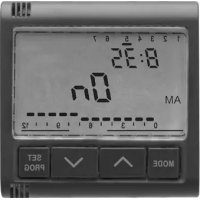
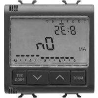
PRODUCT DESCRIPTION
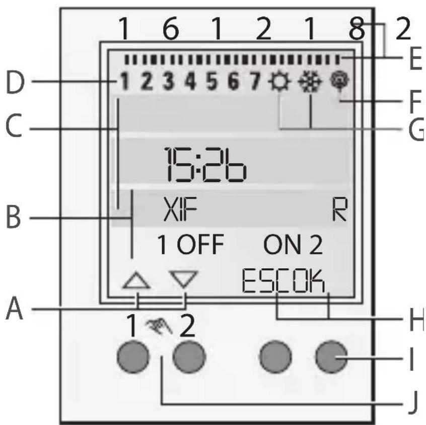
Display and function keys
- Switch-off commands have a higher priority than switch-on commands.
- The central line of the display, in which the adjusted values and selected menu items are displayed, is displayed larger.
- Flashing means that an entry is required. If you do not enter anything within two minutes, the timer switches back to automatic operation.
- “MAINSOFF” appears on the display when the device is not supplied with power.
- “LOW BATT” appears on the display when a battery change is required within the next two weeks.
- The programs are maintained when resetting. You need to readjust date and time. Pres all 4 buttons at the same time to reset the device.
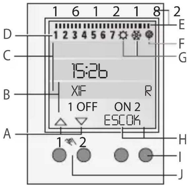
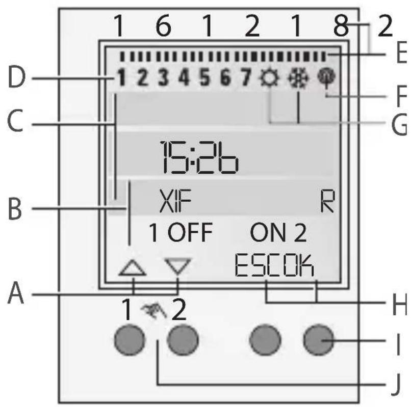
Display
A Function displays of the two left keys
B Switching state displays (ON/OFF/OVR/FIX)
C 3 display lines
D Weekdays
The assignment can be changed in the DATETIME menu, for example to 1 = Sunday.
E Programmed switching times
F Radio antenna
G Display of summer/winter time
H Function displays of the two right keys
Function displays of the two left keys:
△ Scroll upwards in the menu
▽ Scroll downwards in the menu
√ Accept selection/proposal
+ Brief key press = +1 / long key
press (about 2 sec) = fast
forward
- Brief key press = -1 / long key
press (about 2 sec) = fast
forward
Keys/Interfaces
I Right keys
J Left keys with manual switch function in Automatic mode
Function displays of the two right keys:
MENU Leaves Automatic mode and enters Programming mode
ESC Brief key press = one step backward Long key press (about 2 sec) = Back to Automatic mode
OK Make a selection and accept
EDT Change programs in “Read mode”
NO Do not execute command
YES Execute command
DEL Delete
MENU STRUCTURE
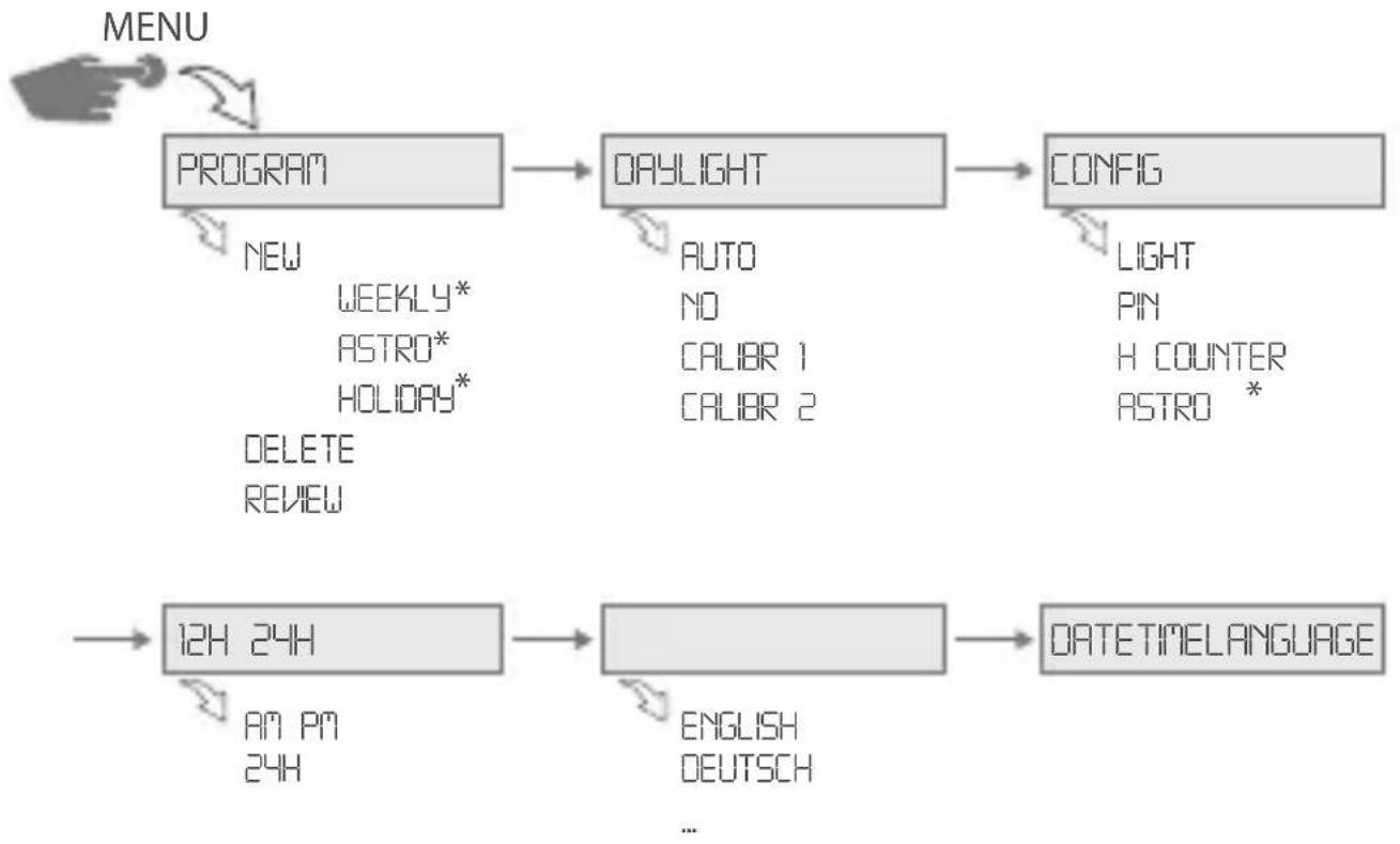
flowchart
graph TD
    A["PROGRAM"] --> B["DAYLIGHT"]
    B --> C["CONFIG"]
    D["12H 24H"] --> E["DATETIME LANGUAGE"]
    F["NEW WEEKLY* ASTRO* HOLIDAY* DELETE REVIEW"] --> A
    G["AUTO NO CALIBR 1 CALIBR 2"] --> B
    H["LIGHT PIN H COUNTER ASTRO *"] --> C
    I["AN PM 24H"] --> E
    J["ENGLISH DEUTSCH ..."] --> E
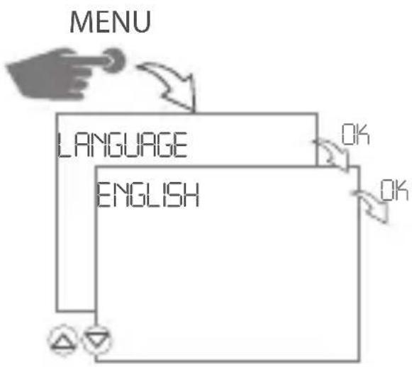
COMMISSIONING - SELECT MENU LANGUAGE
When delivered, the timer is in automatic mode with preset time, date (CET) and menu in English.
Press the Menu button to make set- tings.
Then select the desired setting.
flowchart
graph TD
    A["Hand pointing at MENU"] --> B["Language"]
    B --> C["ENGLISH"]
    C --> D["OK"]
    C --> E["OK"]
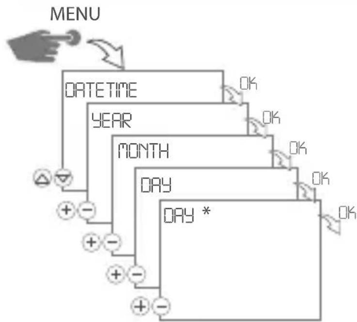
SET DATE AND TIME
flowchart
graph TD
    A["MENU"] --> B["DATETIME"]
    B --> C["YEAR"]
    C --> D["MONTH"]
    D --> E["DAY"]
    E --> F["DAY *"]
    F --> G["OK"]
    style A fill:#f9f,stroke:#333
    style G fill:#bbf,stroke:#333
flowchart
graph TD
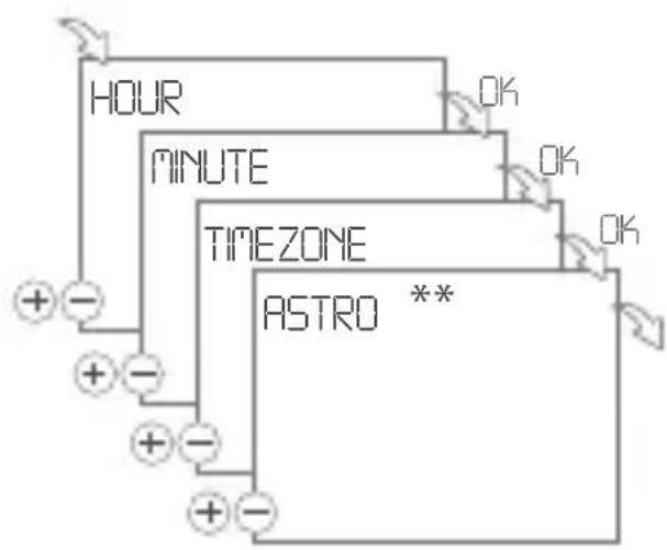
A["HOUR"] --> B["MINUTE"]
B --> C["TIMEZONE"]
C --> D["ASTRO **"]
D --> E["+ -"]
E --> F["+ -"]
F --> G["+ -"]
G --> H["+ -"]
H --> I["+ -"]
I --> J["+ -"]
J --> K["+ -"]
K --> L["+ -"]
L --> M["+ -"]
M --> N["+ -"]
N --> O["+ -"]
O --> P["+ -"]
P --> Q["+ -"]
Q --> R["+ -"]
R --> S["+ -"]
S --> T["+ -"]
T --> U["+ -"]
U --> V["+ -"]
V --> W["+ -"]
W --> X["+ -"]
X --> Y["+ -"]
Y --> Z["+ -"]
Z --> AA["+ -"]
AA --> AB["+ -"]
AB --> AC["+ -"]
AC --> AD["+ -"]
AD --> AE["+ -"]
AE --> AF["+ -"]
AF --> AG["+ -"]
AG --> AH["+ -"]
AH --> AI["+ -"]
AI --> AJ["+ -"]
AJ --> AK["+ -"]
AK --> AL["+ -"]
AL --> AM["+ -"]
AM --> AN["+ -"]
AN --> AO["+ -"]
AO --> AP["+ -"]
AP --> AQ["+ -"]
AQ --> AR["+ -"]
AR --> AS["+ -"]
AS --> AT["+ -"]
AT --> AU["+ -"]
AU --> AV["+ -"]
AV --> AW["+ -"]
AW --> AX["+ -"]
AX --> AY["+ -"]
*) Set the weekday in accordance with the current date.
** ) Only appears when the Astro-settings are not set.
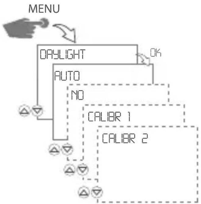
SET DATE AND TIME
flowchart
graph TD
    A["MENU"] --> B["DAYLIGHT"]
    B --> C["AUTO"]
    C --> D["NO"]
    D --> E["CALIBR 1"]
    D --> F["CALIBR 2"]
    E --> G["OK"]
    F --> H["OK"]
The following settings are possible:
AUTO
In-factory default setting as specified by law (USA or EU). It will be recalculated every year.
NO
No changeover.
CALIBR 1 (AUTO)
Manual Programming.
The programmed summer/winter time will be recalculated automatically for each year.
- The change-over always takes place on the first Sunday of the selected month, if the entered date lies between 1. and 15.
- The change-over always takes place on the last Sunday of the selected month, if the entered date lies between 16. and 31.
- The time change-over (summertime/wintertime) occurs on the respective Sunday at 1 o'clock UTC (Coordinated Universal Time).
CALIBR 2 (FIX)
Manual Programming.
The change-over takes place every year always on the same date.
PROGRAMMING
Create a weekly program *
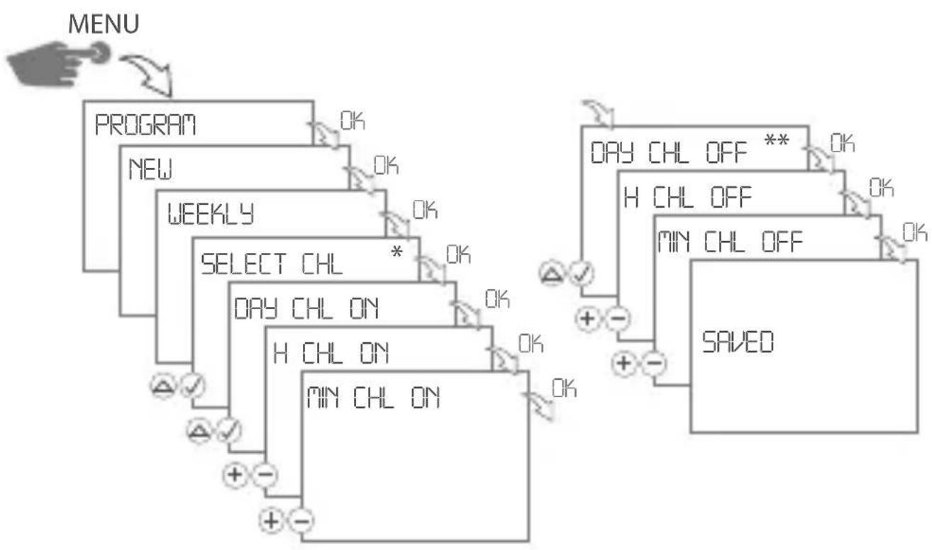
flowchart
graph TD
    A["MENU"] --> B["PROGRAM"]
    B --> C["NEW"]
    C --> D["WEEKLY"]
    D --> E["SELECT CHL *"]
    E --> F["DAY CHL ON"]
    F --> G["H CHL ON"]
    G --> H["MIN CHL ON"]
    H --> I["DAY CHL OFF **"]
    I --> J["H CHL OFF"]
    J --> K["MIN CHL OFF"]
    K --> L["SAVED"]
    style A fill:#f9f,stroke:#333
    style L fill:#ccf,stroke:#333
- Press the MENU KEY.
- Confirm PROGRAM by pressing OK.
- Confirm NEW by pressing OK.
- Confirm WEEKLY by pressing OK.
▷ Free memory locations are briefly displayed.
- When prompted, select channels and confirm by pressing √
→ OK
The weekday display is flashing.
ON command:
- Select the desired days △ and confirm by pressing √
→ OK
-
Enter hour (+/-) → OK
-
Enter minutes (+/-) → OK
OFF command:
- When prompted, select desired days △ and confirm by pressing √
→ OK
-
Enter hour (+/-) → OK
-
Enter minutes (+/-) → OK
The program is saved.
** ) Available only if individual days have been selected for the ON command.
Creating a holiday program \*
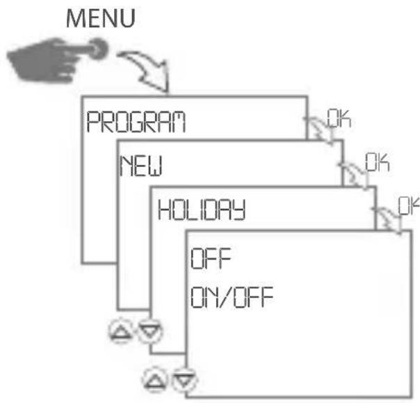
flowchart
graph TD
    A["MENU"] --> B["PROGRAM"]
    B --> C["NEW"]
    C --> D["HOLIDAY"]
    D --> E["OFF"]
    D --> F["ON/OFF"]
    style A fill:#f9f,stroke:#333
    style B fill:#ccf,stroke:#333
    style C fill:#cfc,stroke:#333
    style D fill:#fcc,stroke:#333
    style E fill:#cff,stroke:#333
    style F fill:#ffc,stroke:#333
ON/OFF programming
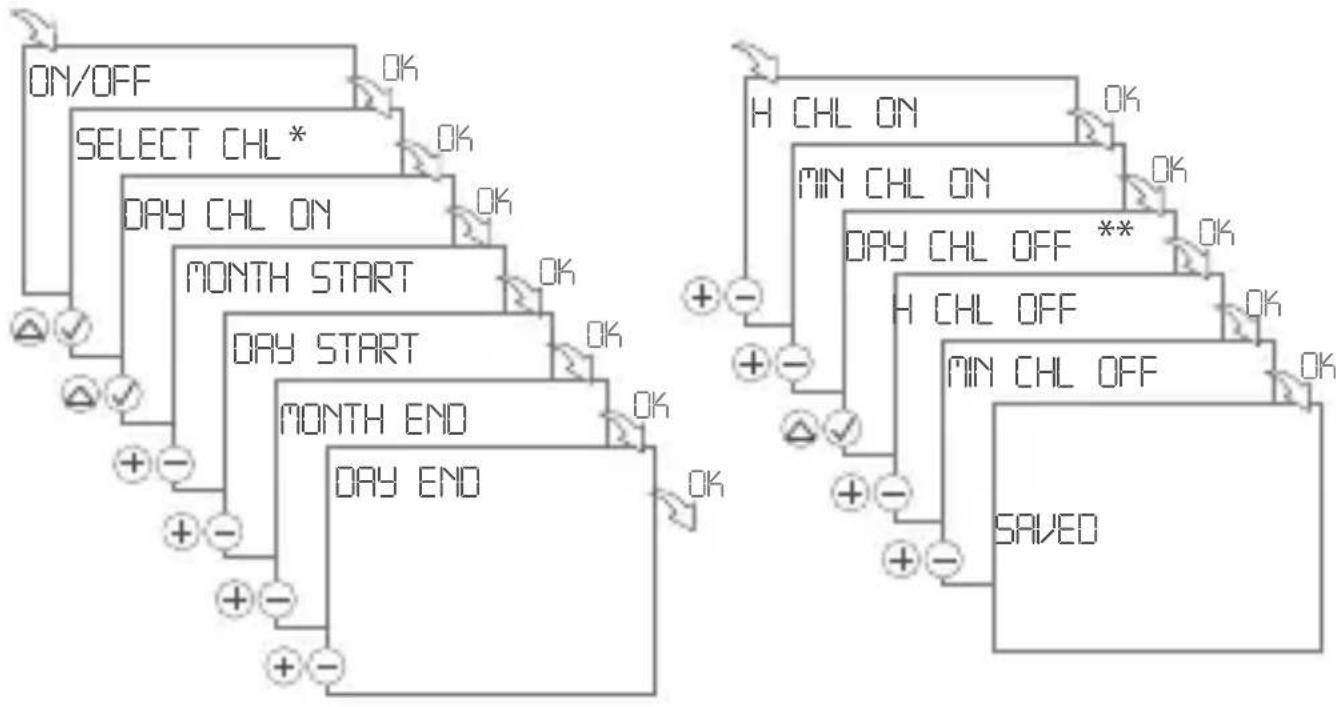
flowchart
graph TD
    A["ON/OFF"] --> B["SELECT CHL*"]
    B --> C["DAY CHL ON"]
    C --> D["MONTH START"]
    D --> E["DAY START"]
    E --> F["MONTH END"]
    F --> G["DAY END"]

    H["H CHL ON"] --> I["MIN CHL ON"]
    I --> J["DAY CHL OFF **"]
    J --> K["H CHL OFF"]
    K --> L["MIN CHL OFF"]
    L --> M["SAVED"]
If OFF is set, you can select the days of the week on which the time switch is switched off during holidays.
The procedure is the same as for creating a weekly program.
Creating an ASTRO program \*
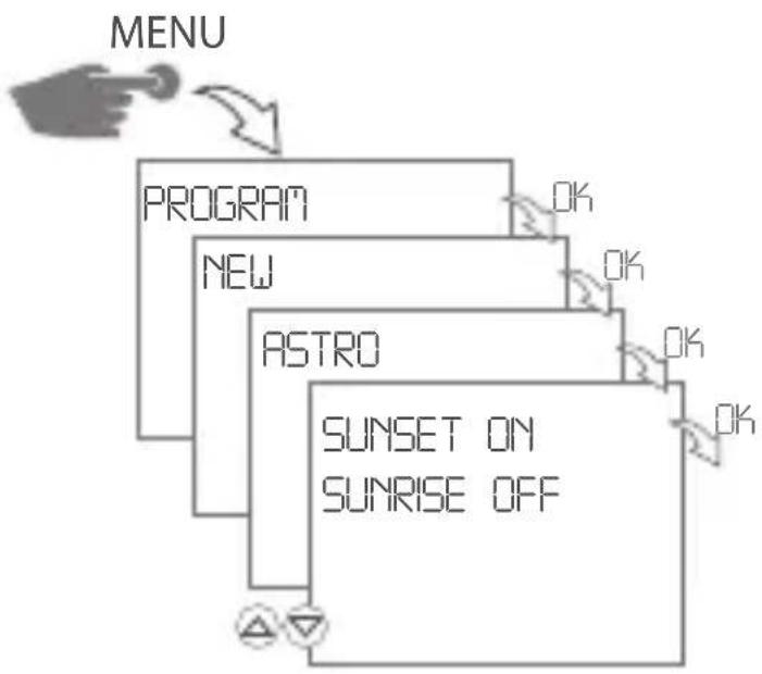
flowchart
graph TD
    A["MENU"] --> B["PROGRAM"]
    B --> C["NEW"]
    C --> D["ASTRO"]
    D --> E["SUNSET ON SUNRISE OFF"]
    style A fill:#f9f,stroke:#333
    style B fill:#ccf,stroke:#333
    style C fill:#cfc,stroke:#333
    style D fill:#fcc,stroke:#333
    style E fill:#cff,stroke:#333
The following settings are possible:
SUNSET ON The time switch switches ON at sunset and SUNRISE OFF switches OFF at sunrise
SUNSET OFF The time switch switches OFF at sunset and SUNRISE ON switches ON at sunrise
SUNRISE PULSE The time switch switches ON at sunrise for a certain time (pulse)
SUNSET PULSE The time switch switches ON at sunset for a certain time (pulse)
SUNRISE The time switch switches ON at sunrise and sunset SUNSET for a certain time (pulse) PULSE
Sunset ON / Sunrise OFF
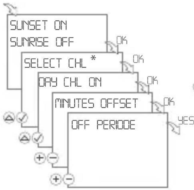
flowchart
graph TD
    A["SUNSET ON"] --> B["OK"]
    C["SUNRISE OFF"] --> B
    D["SELECT CHL *"] --> E["OK"]
    F["DRY CHL ON"] --> G["OK"]
    H["MINUTES OFFSET"] --> I["OK"]
    J["OFF PERIODE"] --> K["YES"]
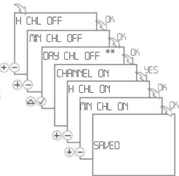
flowchart
graph TD
    A["H CHL OFF"] --> B["OK"]
    C["MIN CHL OFF"] --> D["OK"]
    E["DAY CHL OFF **"] --> F["OK"]
    G["CHANNEL ON"] --> H["YES"]
    I["H CHL ON"] --> J["OK"]
    K["MIN CHL ON"] --> L["OK"]
    M["SAVED"] --> N["+ -"]
    O["+"] --> P["+ -"]
    Q["+"] --> R["+ -"]
    S["+"] --> T["+ -"]
    U["+"] --> V["+ -"]
    W["+"] --> X["+ -"]
- Confirm SUNSET ON / SUNRISE OFF by pressing OK.
▷ Free memory locations are briefly displayed.
2. When prompted, select channels △ and confirm by pressing √ → OK
▷ The weekday display is flashing.
3. Select the desired days △ and confirm by pressing √ → OK
4. Enter minutes for the OFFSET (+/-) → OK
Offset can be used to offset the ON and OFF switching times of the Astro program. This is done in order to adapt them to the local conditions.
Example SUNSET ON / SUNRISE OFF:
Offset = +00:15 The time switch switches ON 15 minutes after the calculated sunrise and switches OFF 15 minutes after the calculated sunset.
- Select the OFF PERIOD: YES or NO
▶ Select YES to set the time period (hours and minutes) during which the time switch should switch off, e.g. nighttime switchoff from 23 - 5 h.
▶ Select NO to set no OFF period.
OFF period: YES
- Enter hour and minute for the OFF command (+/-) → OK
- When prompted, select desired days △ and confirm by pressing √

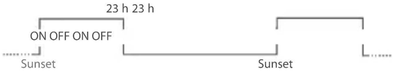
- Select CHANNEL ON: YES or NO
▶ Select YES to set the time period (hours and minutes) during which the time switch should switch on again.
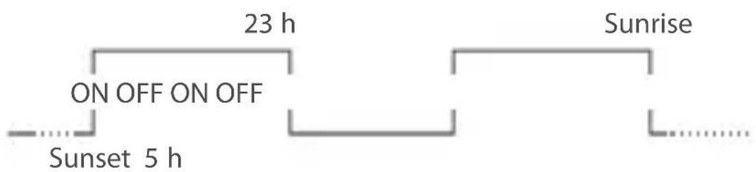
flowchart
graph LR
    A["Sunset 5 h"] --> B["ON OFF ON OFF"]
    B --> C["23 h"]
    C --> D["Sunrise"]
▶ Select NO if the nighttime switch-off should last to the next sunset.
Channel ON: YES
- Enter hour and minute for the ON command (+/-) → OK
The program is saved.
VIEW AND EDIT PROGRAM
Daily, weekly, yearly and astro programs can be viewed and edited separately.
- Press to scroll through the different program steps.
- Press EDT to edit a program. This procedure is similar to creating a new program.
- Press OK to go to the next program.
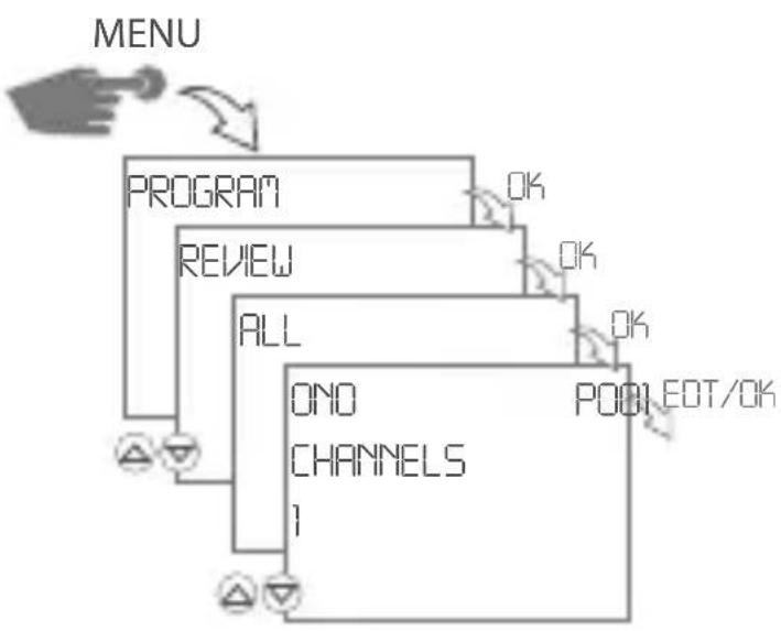
flowchart
graph TD
    A["MENU"] --> B["PROGRAM"]
    B --> C["REVIEW"]
    C --> D["ALL"]
    D --> E["ONO CHANNELS 1"]
    E --> F["P001 EOT/OK"]
    F --> G["OK"]
    G --> H["OK"]
    H --> I["OK"]
    I --> J["OK"]
DELETE PROGRAM
Delete all programs
- Press YES to delete all programs.
- Press NO to delete individual programs.
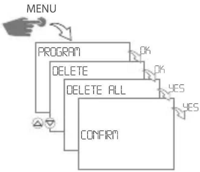
flowchart
graph TD
    A["MENU"] --> B["PROGRAM"]
    B --> C["DELETE"]
    C --> D["DELETE ALL"]
    D --> E["CONFIRM"]
    E --> F["OK"]
    E --> G["OK"]
    E --> H["YES"]
    E --> I["YES"]
Delete individual programs
- Press to scroll through the different program steps.
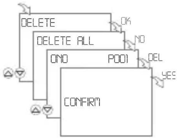
flowchart
graph TD
    A["DELETE"] --> B["DELETE ALL"]
    B --> C["ON/O"]
    C --> D["P001"]
    D --> E["OK"]
    D --> F["NO"]
    D --> G["DEL"]
    G --> H["YES"]
    I["CONFIRM"] --> J["△"]
    I --> K["△"]
CONFIGURATION
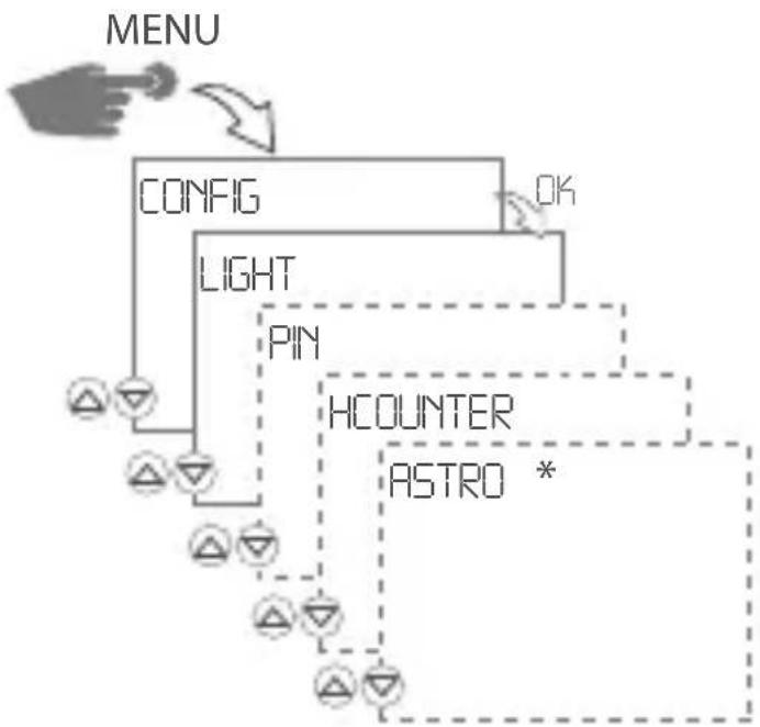
flowchart
graph TD
    A["MENU"] --> B["CONFIG"]
    B --> C["LIGHT"]
    C --> D["PIN"]
    D --> E["HCOUNTER"]
    E --> F["ASTRO *"]
    style A fill:#f9f,stroke:#333
    style B fill:#ccf,stroke:#333
    style C fill:#cfc,stroke:#333
    style D fill:#fcc,stroke:#333
    style E fill:#cff,stroke:#333
    style F fill:#ffc,stroke:#333
ASTRO – Astro settings *
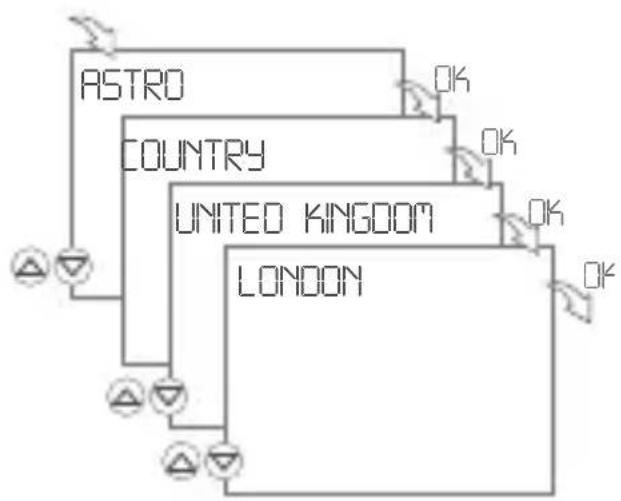
flowchart
graph TD
    A["ASTRO"] --> B["COUNTRY"]
    B --> C["UNITED KINGDOM"]
    C --> D["LONDON"]
    D --> E["OK"]
    style A fill:#f9f,stroke:#333
    style B fill:#ccf,stroke:#333
    style C fill:#cfc,stroke:#333
    style D fill:#fcc,stroke:#333
Click the COUNTRY menu item to select the desired country and city.
The longitudes and latitudes are generated automatically.
If the desired city is not included in the list, you can manually set the longitudes and latitudes via the LAT/LON menu item.
LIGHT – Background illumination
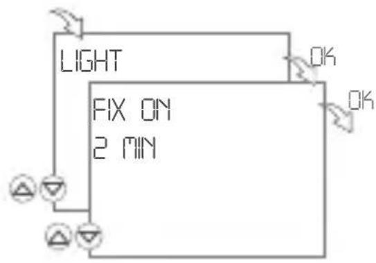
flowchart
graph TD
    A["Light"] --> B["FIX ON 2 MIN"]
    B --> C["OK"]
    style A fill:#f9f,stroke:#333
    style B fill:#ccf,stroke:#333
    style C fill:#cfc,stroke:#333
PIN – Set PIN
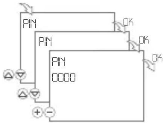
flowchart
graph TD
    A["Pin 0000"] --> B["ON"]
    A --> C["OFF"]
    D["Pin 0000"] --> E["ON"]
    D --> F["OFF"]
    G["Ground"] --> H["+"]
    I["Ground"] --> J["-"]
    K["Ground"] --> L["Ground"]
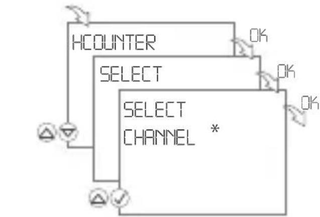
HZAEHLER – Set hour counter
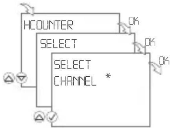
flowchart
graph TD
    A["HCOUNTER"] --> B["SELECT"]
    B --> C["SELECT CHANNEL *"]
    C --> D["OK"]
    C --> E["OK"]
    C --> F["OK"]
    C --> G["OK"]
- Select FIX ON to set the background lighting permanently.
-
Select 2 MIN if you want the background lighting to be automatically switched off 2 minutes after your last input.
-
Press + - to set a numeric value.
- Press OK to set the next number.
- Select NO PIN, to remove the PIN.
flowchart
graph TD
    A["HCOUNTER"] --> B["SELECT"]
    B --> C["SELECT CHANNEL *"]
    C --> D["OK"]
    C --> E["OK"]
    C --> F["OK"]
    C --> G["OK"]
    C --> H["OK"]
- Press to select the channels.
- Select REVIEW to check the hour counter.
- Press to scroll through the different program steps
- Press RES to reset the hour counter for this channel.
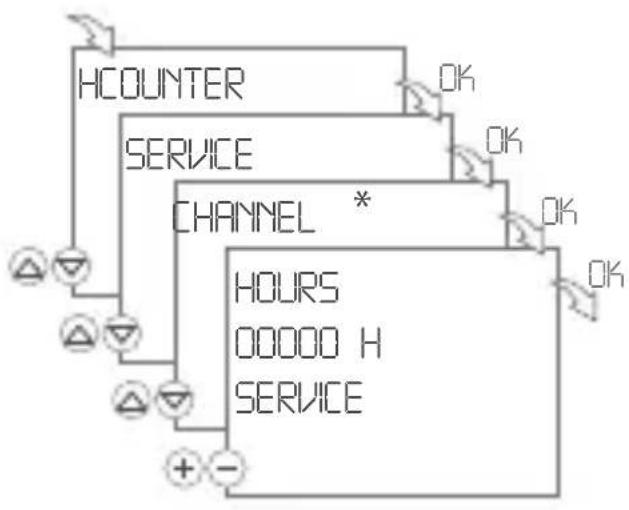
HCOUNTER – Set service counter
flowchart
graph TD
    A["HCOUNTER"] --> B["SERVICE"]
    B --> C["CHANNEL *"]
    C --> D["HOURS"]
    D --> E["OOOOO H"]
    E --> F["SERVICE"]
    F --> G["+ -"]
    G --> A
    style A fill:#f9f,stroke:#333
    style B fill:#ccf,stroke:#333
    style C fill:#cfc,stroke:#333
    style D fill:#fcc,stroke:#333
    style E fill:#cff,stroke:#333
    style F fill:#ffc,stroke:#333
You can set the number of operating hours after which a service message is to appear. It will be shown on the display as soon as the counter has reached the number of hours set by you.
- Press to select the channels.
- Press + - to set a numeric value.
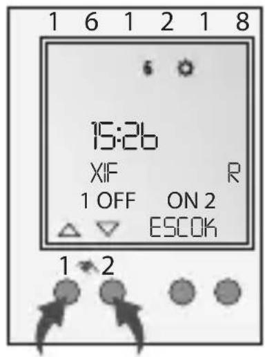
AUTOMATIC/MANUAL MODE
- Manual switch: Duration ON / Duration OFF / OVR / Automatic mode
- Left button = channel 1 / Right button = channel 2
Press 1x = FIX ON = Duration ON Press 2x = FIX OFF = Duration OFF Press 3x = OVR = Override mode Press 4x = Automatic mode
OVERRIDE MODE
The Override function (temporary program overwrite) allows the user to finish the currently running program prematurely or start a program to run later before its scheduled start. This depends
of the current channel status. The Override function applies only to the current program and remains active until the next program change. After that, the timer returns to Automatic mode.
MAINTENANCE AND REPAIR
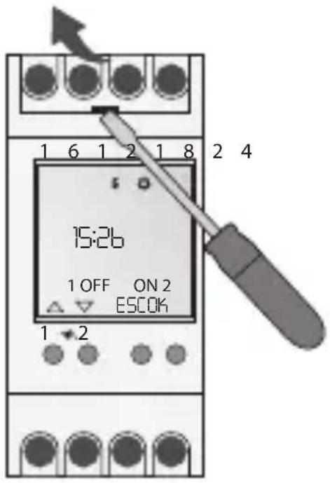
BATTERY CHANGE
Before changing the battery, the device must be disconnected from the power supply! Date and time will get lost!
- Lift the battery compartment using a screwdriver.
- Take the battery out of the support.
- Insert new (Lithium battery type CR2032) battery into support. Observe polarity of the battery!
- Push battery support downward until it engages.
- Dispose of the battery in an environmentally friendly manner.
TECHNICAL DATA
Dimensions Hx W x D (mm) 45 x 35 x 60
Weight g (approx.) 220
Main voltage See rating plate
Protection class II
Power consumption 1 VA
Switching capacity
- Ohmic load (VDE, IEC) 16 A / 250 V AC
- Inductive load cos φ 0.6 8 A / 250 V AC
- Incandescent-/Halogen lamp load 2000 W
- Fluorescent lamp 1000 W
- Rated load AC1 / AC15 3700W / 750W
Switching contacts Change-over contact
Ambient temperature -10°C... +55°C
natural_image
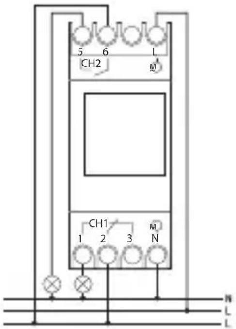
Abstract geometric shape with a black arrow pointing to a white square, no text or symbols present.SCHEMA DE BRANCHEMENT
$$ \begin{array}{l} \mathrm{CH1=canal1} \ \mathrm {CH2 = canal 2 ^ {*}} \end{array} $$
DESCRIPTION DU PRODUIT
natural_image
Abstract geometric shape with a black arrow pointing to a white square cutout (no text or symbols)ESQUEMA DE CONEXIÓN
$$ \begin{array}{l} \mathrm{CH1=canal1} \ \mathrm {CH2 = canal 2 ^ {*}} \end{array} $$
natural_image
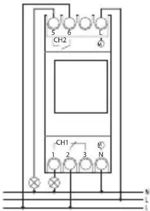
Abstract geometric shape with a black arrow pointing to a white square cutout (no text or symbols)ANSCHLUSSPLAN
$$ \begin{array}{l} \mathrm{CH1} = \text { K a n a l } 1 \ \mathrm{CH2} = \text { Kanal } 2 ^ {*} \ \end{array} $$
PRODUKTBESCHREIBUNG
Dispose of the packing material correctly according to legal requirements and regulations. Observe the following notes for disposing of defective system components or the system after its service life:
- Dispose of appropriately, i.e. separating the parts to be disposed of according to material groups.
- Do not throw electrical and electronic components in the bin. Bring these parts to the recycling centers.
- Always ensure the environmentally sound disposal conform to the state-of-the-art environment protection, recycling and disposal engineering.

According to article 9 paragraph 2 of the European Directive 2004/108/EC and to article R2 paragraph 6 of the Decision 768/2008/EC, the responsible for placing the apparatus on the Community market is:
GEWISS S.p.A Via A. Volta, 1 - 24069 Cenate Sotto (BG) Italy Tel: +39 035 946 111 Fax: +39 035 945 270 E-mail: qualitymarks@gewiss.com


+39 035 946 111
8.30 - 12.30 / 14.00 - 18.00
- GENERAL INFORMATION
- PRODUCT DESCRIPTION
- Display and function keys
- Display
- Function displays of the two left keys:
- Keys/Interfaces
- Function displays of the two right keys:
- COMMISSIONING - SELECT MENU LANGUAGE
- SET DATE AND TIME
- AUTO
- NO
- CALIBR 1 (AUTO)
- CALIBR 2 (FIX)
- PROGRAMMING
- ON command:
- OFF command:
- Creating a holiday program \*
- ON/OFF programming
- Creating an ASTRO program \*
- Sunset ON / Sunrise OFF
- OFF period: YES
- Channel ON: YES
- VIEW AND EDIT PROGRAM
- DELETE PROGRAM
- Delete all programs
- Delete individual programs
- CONFIGURATION
- LIGHT – Background illumination
- PIN – Set PIN
- HZAEHLER – Set hour counter
- HCOUNTER – Set service counter
- AUTOMATIC/MANUAL MODE
- OVERRIDE MODE
- MAINTENANCE AND REPAIR
- BATTERY CHANGE
- TECHNICAL DATA
- DESCRIPTION DU PRODUIT
- PRODUKTBESCHREIBUNG
Brand : Gewiss
Model : GW96845
Category : Digital timer switch