
GW20825 - Digital timer switch Gewiss - Free user manual and instructions
Find the device manual for free GW20825 Gewiss in PDF.
| Product Type | Programmable digital time switch |
| Brand | Gewiss |
| Model | GW20825 |
| Category | Digital time switch |
| Power supply | 230 V ~ (mains); rechargeable battery ML 1220 (backup) |
| Dimensions (format) | 2 modules (Playbus or System) |
| Display | Backlit LCD |
| Programming | Daily and weekly, up to 12 switchings per hour, 5-minute step |
| Operating modes | Automatic, manual, Off |
| Relay output | 1 NO/NC, 8 A (AC1) / 4 A (AC15), 250 V~ |
| Remote control | Via GSM system GW90821 (SMS) |
| Backup in case of power failure | Backup battery (24 h autonomy) |
| Installation | Flush or surface mounting on DIN rail (via supports) |
| Protection class | Indoor use, environment free of dust and water |
| Standards | Compliant with national standards and IEC 60364 / HD 60364 |
| Maintenance | Clean with a dry cloth; do not use abrasive products |
| Spare parts / repairability | Replaceable battery (ML 1220); no other user-serviceable parts |
| Safety | Follow installation and operating instructions strictly |
| Provided accessories | Instruction manual |
Frequently Asked Questions - GW20825 Gewiss
User questions about GW20825 Gewiss
0 question about this device. Answer the ones you know or ask your own.
Ask a new question about this device
Download the instructions for your Digital timer switch in PDF format for free! Find your manual GW20825 - Gewiss and take your electronic device back in hand. On this page are published all the documents necessary for the use of your device. GW20825 by Gewiss.
USER MANUAL GW20825 Gewiss
natural_image
Technical line drawing of an air conditioner unit with internal components and a separate cover (no text or symbols)Warning ! The safety of this appliance is only guaranteed if all the instructions given here are followed scrupulously.
These should be read thoroughly and kept in a safe place.
System-Playbus products can be installed in environments which are dust-free and where no special protection against the penetration of water is required.
They shall be installed in compliance with the requirements for household devices set out by the national standards and rules applicable to low-voltage electrical installations which are in force in the country where the products are installed, or, when there are none, following the international standard for low-voltage electrical installations IEC 60364, or the European harmonization document HD 60364.
GEWISS sales organization is ready to provide full explanations and technical data on request.
CONTENTS
USER INSTRUCTIONS page
- General description 20
- Control description 21
- Operating modes.... 22
- Setting parameters.... 23
- Programming 24
- Automatic operation 26
- Manual operation 26
- Visual display unit.... 27
- Remote control.... 27
- Operating in case of blackout.... 28
- Preset parameters.... 28
INSTALLATION INSTRUCTIONS
- Assembly 29
- Terminal description 30
- Battery removal.... 30
FUNCTIONAL FEATURES/TECHNICAL DATA.... 31
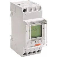
General description
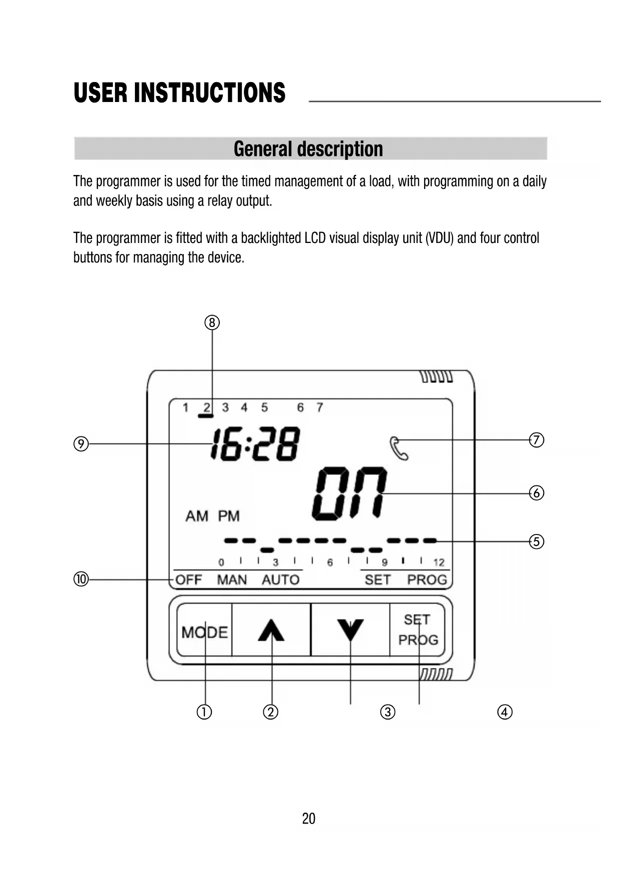
The programmer is used for the timed management of a load, with programming on a daily and weekly basis using a relay output.
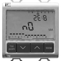
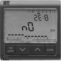
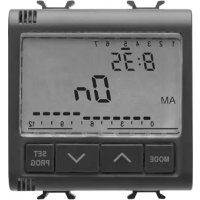
The programmer is fitted with a backlighted LCD visual display unit (VDU) and four control buttons for managing the device.
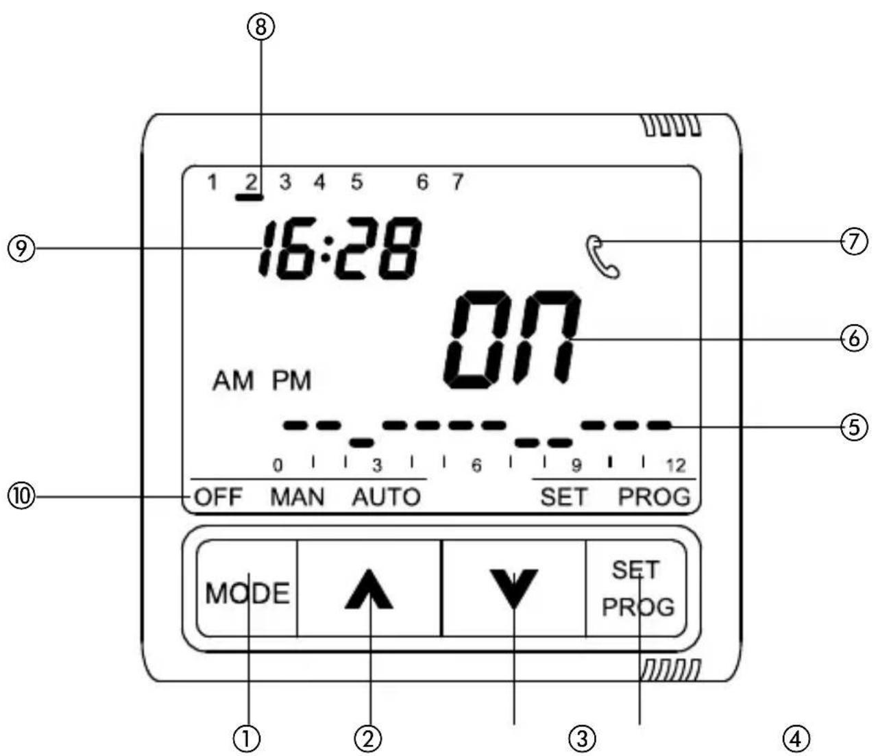
Control description
| USER INSTRUCTIONS | Symbol |
| 1 MODE: select mode | MODE |
| 2 Increment/Select parameters | |
| 3 Decrement/Select parameters | |
| 4 SET/PROG: Set programs/Programming | SET/PROG |
| VDU SIGNALS | |
| 5 Daily program profile | |
| 6 Relay status (ON/OFF) | |
| 7 Command signal by GSM remote control unit (via SMS) | |
| 8 Day | |
| 9 Time | |
| 10 Operating mode | OFF MAN AUTO |
Warning: at switch-on the programmer carries out a self-diagnosis of approximately 15 seconds displaying all the icons on the VDU.
Operating mode
The programmer provides three different operating modes:
- MANUAL
- AUTOMATIC
- OFF
The MODE key is used to switch from one mode to another.
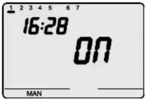
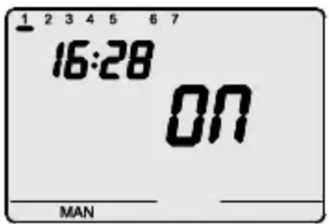
In manual mode it is possible to set the output in a permanent state. The time, the day of the week, the message MAN and the indication of the relay status (ON/OFF) are displayed on the VDU.
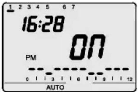
In automatic mode the device uses a program set by the user, which can also be differentiated for each day of the week. The time, the day of the week, the message AUTO and the current relay status (ON/OFF) are displayed on the VDU. The message AM or PM shows which fraction of the day is displayed in the hourly profile.
The segment relative to the current time blinks in the hourly profile with the representation of the status of the output (high segment ON, low segment OFF).
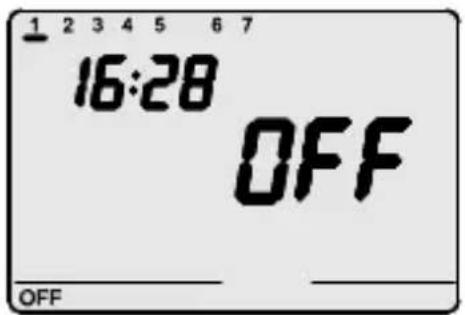
In OFF mode the N.A. relay contact is kept constantly open while the N.C. contact is closed.
The time, the day of the week and the message and indication of the relay status (OFF) are displayed on the VDU.
Setting parameters
The SET/PROG key is pressed once to set the parameters.
The message SET is displayed on the VDU.
At this point the following can be modified, in sequence:
- the day of the week
- the hour
- the minutes
The value of each parameter is confirmed by pressing the MODE key.
The setting phase is exited by pressing the SET key again or, in automatic mode, 30 seconds after the last key entry.
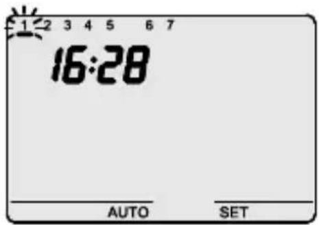
Setting the day of the week
When the day of the week bar blinks, select the day of the week using the keys(Monday=1, Tuesday=2.....
Sunday=7).
The value set is confirmed by pressing the MODE key within 30 seconds.
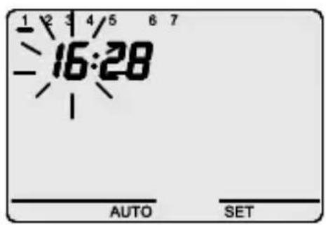
Setting the hour
When the hour figures blink, set the hour using the A V keys.
The values set are confirmed by pressing the MODE key within 30 seconds.
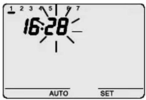
Setting the minutes
When the minutes figures blink, set the minutes using the keys.
The values set are confirmed by pressing the MODE key within 30 seconds.
Programming
The SET/PROG key is pressed twice to personalise the preset daily/weekly program or to make a modification to a previously set cycle.
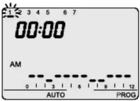
a) The message PROG is displayed on the VDU while the bar for the first day of the week starts to blink.
The required day is selected with the keys
The selection is confirmed by pressing the MODE key within 30 seconds.
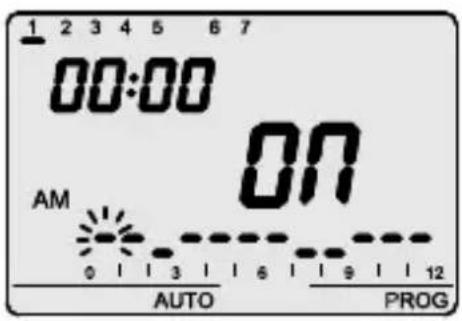
b) The profile of the day selected is displayed on the VDU. c) The time starts to blink.
The keys are used to select the start hour from which it is required to modify the proposed profile; while the time profile is being incremented, the column relative to the selected time will blink. The selection is confirmed by pressing the MODE key within 30 seconds.
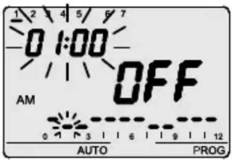
The message ON (or OFF) blinks on the VDU.
The keys can be used to modify the output status,
The modification takes effect starting from the time selected and extends until the next transition or until the end of the day that is being programmed if there are no subsequent transitions.
The choice is confirmed by pressing the MODE key within 30 seconds.
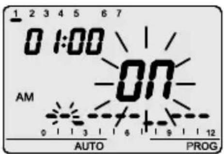
Programming
e) The time blinks, select the start hour from which it is required to select a new switch as described in point c).
The time is incremented/decremented in steps of 5 minutes each time the keys are pressed.
It is therefore possible to define up to 12 relay switches every hour.
The programming is confirmed by prolonged pressure on the MODE key.
A move is made automatically to programming the next day.
The programming phase is exited by pressing the SET key or, in automatic mode, 30 seconds after the last key entry.
Save and propose again
If, however, it is required to copy the program directly to the next day, the programming just done is confirmed by pressing the keys simultaneously 30 seconds.
In this mode the program just run is saved and also proposed again the next day; to copy and save the same program over several days, repeat the operation of simultaneously pressing the keys within 30 seconds.
On completion of weekly programming the SET/PROG key is pressed to return to normal operating.
Automatic operation
The program is started by selecting automatic mode by pressing the MODE key until the AUTO symbol is displayed on the VDU.
In AUTO operating mode the hourly profile relative to the fraction of the day in progress (AP/PM) is displayed.
The profile relative to the other fraction of the day can be displayed by pressing the AV keys simultaneously. The indication is active for 5 seconds, after which the current profile reappears.
Manual operation
The manual operating mode activated by pressing the MODE key until the MAN message is displayed on the VDU.
The keys are used to set the required output status. The selected status (ON/OFF) is displayed on the VDU.
Visual display unit
The LCD visual display unit is provided with backlighting which is active for 5 secs whenever a key is pressed.
In SET or PROG mode the backlighting remains active during parameter setting and programming. It is deactivated on exit from these modes.
Remote control
The programmer can be connected to the GW90821 GSM remote control unit using a serial connection. SMS commands (e.g. from a cellular telephone) can be used to:
- Set the operating mode (MAN/AUTO/OFF)
- Set the output status (ON/OFF)
- Request the current status
Each command SMS sent to the device will be answered by a corresponding SMS in confirmation (with non-configurable predefined text); the status request message provides a reply including the following information:
- current operating mode (OFF/AUTO/MAN)
- output status (ON/OFF)
Whenever the output status or operating mode are modified from the remote control unit, the symbol is displayed on the VDU.
The symbol also appears for the current contact status request. The symbol remains displayed on the VDU until a key is pressed.
Operating in case of blackout
The device is fitted with a backup battery that guarantees updating of the time and day of the week in case of blackout.
When power is supplied by the battery alone there is an autonomy of 24 hours in the following conditions:
- time display active
- backlighting inactive
- output status display inactive
- relay switching not enabled (the relay contact retains the status prior to the blackout)
- front keys inactive (except when all 4 keys are pressed simultaneously)
In the absence of power, simultaneously pressing all four front keys causes disconnection of the backup battery inside the device.
This function is used to preserve the efficiency of the battery when the device is not used for a long period.
The battery is connected again automatically once the device has been connected to the power mains.
The set programs are not lost either in the case of a blackout or in that of battery disconnection.
Preset parameters
| Day of the week | 1 : Monday |
| Time | 00:00 |
| Output status (MAN mode) | OFF (MAN) |
INSTALLATION INSTRUCTIONS
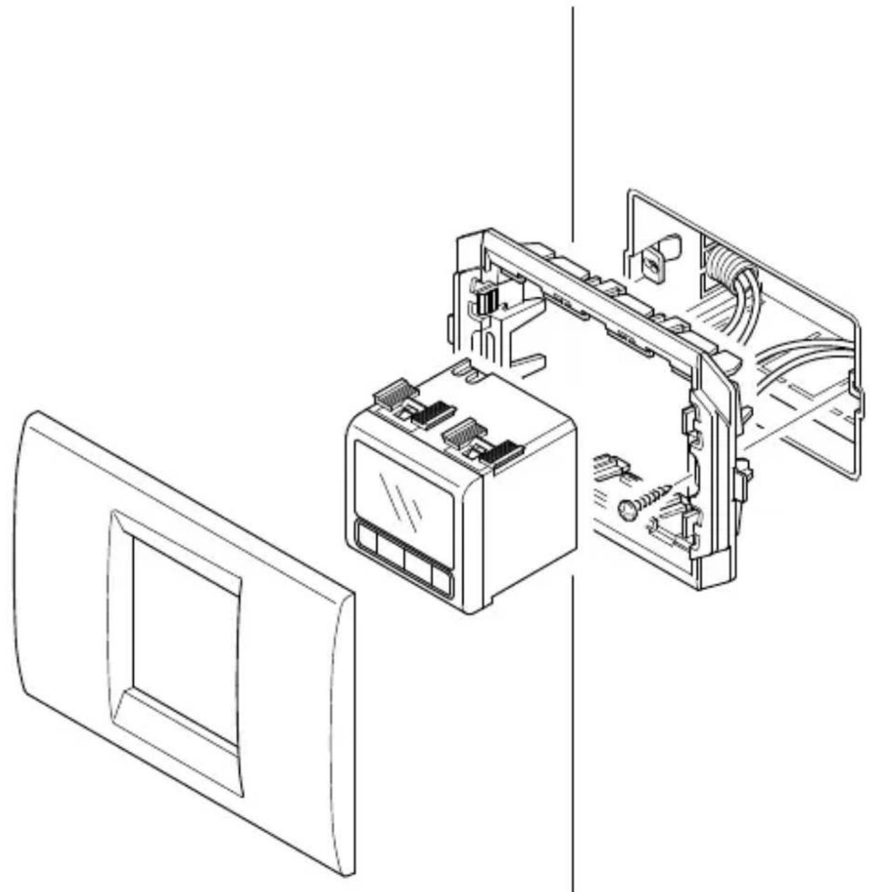
Assembly
Example of installation using plates and 2 module supports (Playbus for GW30413 or System for GW20825 -GW21825)
natural_image
Technical line drawing of an air conditioner unit with internal components and wiring (no text or symbols)INSTALLATION INSTRUCTIONS
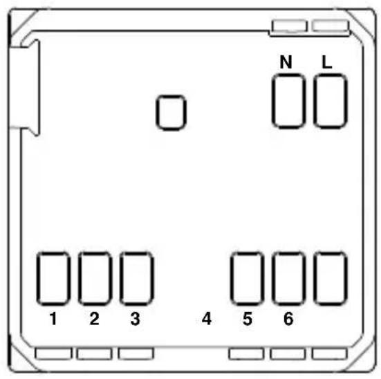
Terminal description


Cabling terminals
Power supply
L - Phase
N - Neutral
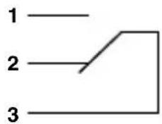
Output relay
1 - NA contact
2 - NC contact
3 - Common
Serial line
4 - TX (output data)
5 - GND (common)
6 - RX (input data)
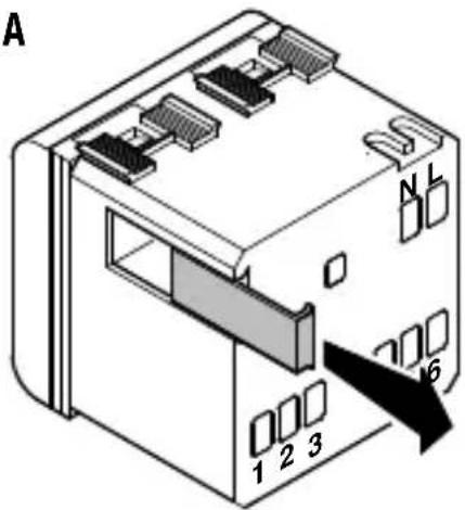
Battery removal
A
B
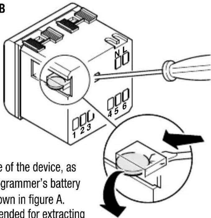
In case of necessity (e.g. having to dispose of the device, as laid down by the WEEE standards), the programmer's battery is accessible by removing the cover as shown in figure A. The use of a small screwdriver is recommended for extracting the battery as shown in figure B.
TECHNICAL DATA
Operating modes
Time programming resolution
Max. n° of settable relay switches
Remote control
Output contact
Power supply
Dimensions
Automatic, manual, off
5 minutes
12 per hour
With GW 90821 GSM remote control unit
Relay, without potential
1 NA/NC 8A (AC1)/4A (AC15), 250Vac
Mains (230V ac) – normal operation
Rechargeable battery (ML1220) – mains blackout
2 Playbus or System modules
FRANÇAIS
ATTENTION - IMPORTANT
Programmation minutes
natural_image
Technical line drawing of an air conditioner unit with internal components and a separate panel (no text or symbols)INSTRUCTIONS POUR L'INSTALLATION
Description bornes
Bornes de câblage
Alimentation
L - Phase
N - Neutre
Relais de sortie
1 - Contact NO
2 - Contact NF
3 - Commun
Ligne sérielle
Descripción mandos
natural_image
Technical line drawing of an air conditioner unit with internal components and a separate panel (no text or symbols)natural_image
Technical line drawing of an air conditioner unit with internal components and a separate panel (no text or symbols)Automatisch, manuell, off.
5 Minuten
12 in der Stunde
According to article 9 paragraph 2 of the European Directive 2004/108/EC and to article R2 paragraph 6 of the Decision 768/2008/EC, the responsible for placing the apparatus on the Community market is:
GEWISS S.p.A Via A. Volta, 1 - 24069 Cenate Sotto (BG) Italy Tel: +39 035 946 111 Fax: +39 035 945 270 E-mail: qualitymarks@gewiss.com


+39 035 946 111
8.30 - 12.30 / 14.00 - 18.00

- CONTENTS
- USER INSTRUCTIONS page
- INSTALLATION INSTRUCTIONS
- FUNCTIONAL FEATURES/TECHNICAL DATA.... 31
- General description
- Operating mode
- Setting parameters
- Setting the day of the week
- Sunday=7).
- Setting the hour
- Setting the minutes
- Programming
- Save and propose again
- Automatic operation
- Manual operation
- Visual display unit
- Remote control
- Operating in case of blackout
- Assembly
- Terminal description
- Cabling terminals
- Battery removal
- TECHNICAL DATA
- FRANÇAIS
- ATTENTION - IMPORTANT
- Programmation minutes
- INSTRUCTIONS POUR L'INSTALLATION
- Description bornes
- Bornes de câblage
Brand : Gewiss
Model : GW20825
Category : Digital timer switch