DML430A - Multimeter GREENLEE - Free user manual and instructions
Find the device manual for free DML430A GREENLEE in PDF.
| Product type | Digital multimeter |
| Brand | Greenlee |
| Model | DML430A |
| Power supply | 9V battery (NEDA 1604, JIS 006P or IEC 6F22) |
| Display | Backlit LCD with dual display and 41-segment bar graph |
| Maximum voltage | 1000 V AC/DC (CAT IV) |
| Maximum current | 10 A (continuous), 20 A max 30 s (AC/DC) |
| Main functions | AC/DC voltage, AC/DC current, frequency, resistance, capacitance, conductance, temperature (type K), diode, continuity, electric field detection (EF), AutoCheck™ mode, data recording |
| Special measurement mode | True RMS AC+DC, peak, MAX-MIN, average (except DML-430A), relative zero, hold (HOLD) |
| Data recording | Up to 87,000 measurements in single display, adjustable interval (0.05 s to 600 s) |
| Computer interface | Optional: DMSC-9U, optical isolation, Windows compatible |
| Safety | Double insulation, CAT IV 1000 V, protection fuses (0.44 A/1000 V and 11 A/1000 V) |
| Fuses | F 0.44 A/1000 V (mA/μA) and F 11 A/1000 V (A) |
| Approximate dimensions | 200 x 90 x 50 mm |
| Approximate weight | 400 g (with battery) |
| Operating temperature | 0°C to 45°C, 0% to 80% RH |
| Maintenance and cleaning | Damp cloth with mild detergent; remove battery if unused for more than 60 days |
| Warranty | Limited lifetime warranty |
| Country of manufacture | USA |
Frequently Asked Questions - DML430A GREENLEE
User questions about DML430A GREENLEE
0 question about this device. Answer the ones you know or ask your own.
Ask a new question about this device
Download the instructions for your Multimeter in PDF format for free! Find your manual DML430A - GREENLEE and take your electronic device back in hand. On this page are published all the documents necessary for the use of your device. DML430A by GREENLEE.
USER MANUAL DML430A GREENLEE
INSTRUCTION MANUAL MANUAL DE INSTRUCCIONES MANUEL D'INSTRUCTIONS

GREENLEE
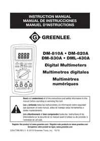
DM-810A · DM-820A DM-830A · DML-430A
Read and understand all of the instructions and safety information in this manual before operating or servicing this tool.
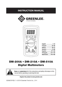
The Greenlee DM-810A, DM-820A, DM-830A, and DML-430A Digital Multimeters are hand-held testing devices with the following measurement capabilities: AC and DC voltage, AC and DC current, frequency, resistance, capacitance, and duty cycle of logic level signals. They also check diodes and verify continuity. All meters feature true RMS AC measurements, a relative zero mode, data hold mode, and an intelligent automatic power off. An optional optically isolated computer interface with software facilitates the recording of readings from the meter to a computer.
Other specialized capabilities and functions common to all meters include:
- Dual display shows two measurements, such as AC voltage and frequency, at the same time.
Backlighted LCD for reading in dim conditions. - Beep-Jack™ audible warning alerts the user with a beep and an error message on the LCD if the test lead is plugged into the mA/μA or A input terminal while the selector switch is not in the mA/μA or A position.
- Bar graph display, which responds more quickly than the numeric display — useful for detecting faulty contacts, potentiometer clicks, and signal spikes.
The DM-820A, DM-830A, and DML-430A multimeters have the following additional capabilities: temperature (K-type thermocouples only); conductance; a crest function, which captures voltage or current signal peaks; and a recording function, which stores the maximum, minimum, and difference (maximum-minimum) input readings. The DM-820A and DM-830A record function can also calculate the average reading. These two models also have non-contact and single-probe voltage detection.
The DM-830A and the DML-430A multimeters have an AutoCheck™ function for automatic selection of AC voltage, DC voltage, and resistance with low input impedance to mask "ghost" voltages. Both multimeters feature a T1-T2 function, which can measure and display two temperatures and calculate the difference. They also feature AC + DC true RMS measurement capability. The DM-830A has a dBm function with selectable reference impedances. The DML-430A has the capability to store data.
Safety
Safety is essential in the use and maintenance of Greenlee tools and equipment. This instruction manual and any markings on the tool provide information for avoiding hazards and unsafe practices related to the use of this tool. Observe all of the safety information provided.
Purpose of This Manual
This instruction manual is intended to familiarize all personnel with the safe operation and maintenance procedures for the Greenlee DM-810A, DM-820A, DM-830A, and DML-430A Digital Multimeters.
Keep this manual available to all personnel. Replacement manuals are available upon request at no charge at www.greenlee.com.

Do not discard this product or throw away! For recycling information, go to www.greenlee.com.
Important Safety Information

SAFETY ALERT SYMBOL
This symbol is used to call your attention to hazards or unsafe practices which could result in an injury or property damage. The signal word, defined below, indicates the severity of the hazard. The message after the signal word provides information for preventing or avoiding the hazard.
DANGER
Immediate hazards which, if not avoided, WILL result in severe injury or death.
WARNING
Hazards which, if not avoided, COULD result in severe injury or death.
CAUTION
Hazards or unsafe practices which, if not avoided, MAY result in injury or property damage.
WARNING
Read and understand this material before operating or servicing this equipment. Failure to understand how to safely operate this tool could result in an accident causing serious injury or death.

WARNING
Electric shock hazard: Contact with live circuits could result in severe injury or death.
All specifications are nominal and may change as design improvements occur. Greenlee Tools, Inc. shall not be liable for damages resulting from misapplication or misuse of its products.
Registered: The color green for electrical test instruments is a registered trademark of Greenlee Tools, Inc.
AutoCheck and Beep-Jack are trademarks of BTC.
Microsoft and Windows are registered trademarks of Microsoft Corporation.
Important Safety Information
| ▲WARNING |
| Electric shock and fire hazard:Do not expose this unit to rain or moisture.Do not use the unit if it is wet or damaged.Only use the test leads provided with the equipment or UL Listed Probe Assembly with same rating or better.Inspect the test leads or accessory before use. They must be clean and dry, and the insulation must be in good condition. Do not use the test lead if the contrasting inner layer of insulation is visible.Use this unit for the manufacturer's intended purpose only, as described in this manual. Any other use can impair the protection provided by the unit.Failure to observe these warnings could result in severe injury or death. |
| ▲WARNING |
| Electric shock hazard:Do not apply more than the rated voltage between any two input terminals, or between any input terminal and earth ground.Do not contact the test lead tips or any uninsulated portion of the accessory.Failure to observe these warnings could result in severe injury or death. |
| ▲WARNING |
| Electric shock hazard:Do not operate with the case open.Before opening the case,remove the test leads from the circuit and shut off the unit.Failure to observe these warnings could result in severe injury or death. |
| ▲WARNING |
| Electric shock hazard: The fuses are an integral part of the overvoltage protection. When fuse replacement is necessary, refer to “Specifications” for the correct type, size, and capacity. Using any other type of fuse will void the overvoltage protection rating of the unit. Failure to observe this warning could result in severe injury or death. |
Important Safety Information
| ▲WARNING |
| Electric shock hazard: • Unless measuring voltage, current, or frequency, shut off and lock out power. Make sure that all capacitors are discharged. Voltage must not be present. • Set the selector and connect the test leads so that they correspond to the intended measurement. Incorrect settings or connections can result in a blown fuse. • Using this unit near equipment that generates electromagnetic interference can result in unstable or inaccurate readings. Failure to observe these warnings could result in severe injury or death. |
| ▲CAUTION |
| Electric shock hazard:Do not change the measurement function while the test leads are connected to a component or circuit.Failure to observe this precaution may result in injury and can damage the unit. |
| ▲CAUTION |
| Electric shock hazard:Do not use the tester to measure voltages in circuits that could be damaged or activated by the AutoCheck™ mode's low input impedance (approximately 3.0 kΩ and 150 pF).Failure to observe this precaution may result in injury and can damage the unit. |
| ▲CAUTION |
| Electric shock hazard:Do not attempt to repair this unit. It contains no user-serviceable parts.Do not expose the unit to extremes in temperature or high humidity. Refer to "Specifications."Failure to observe these precautions may result in injury and can damage the unit. |
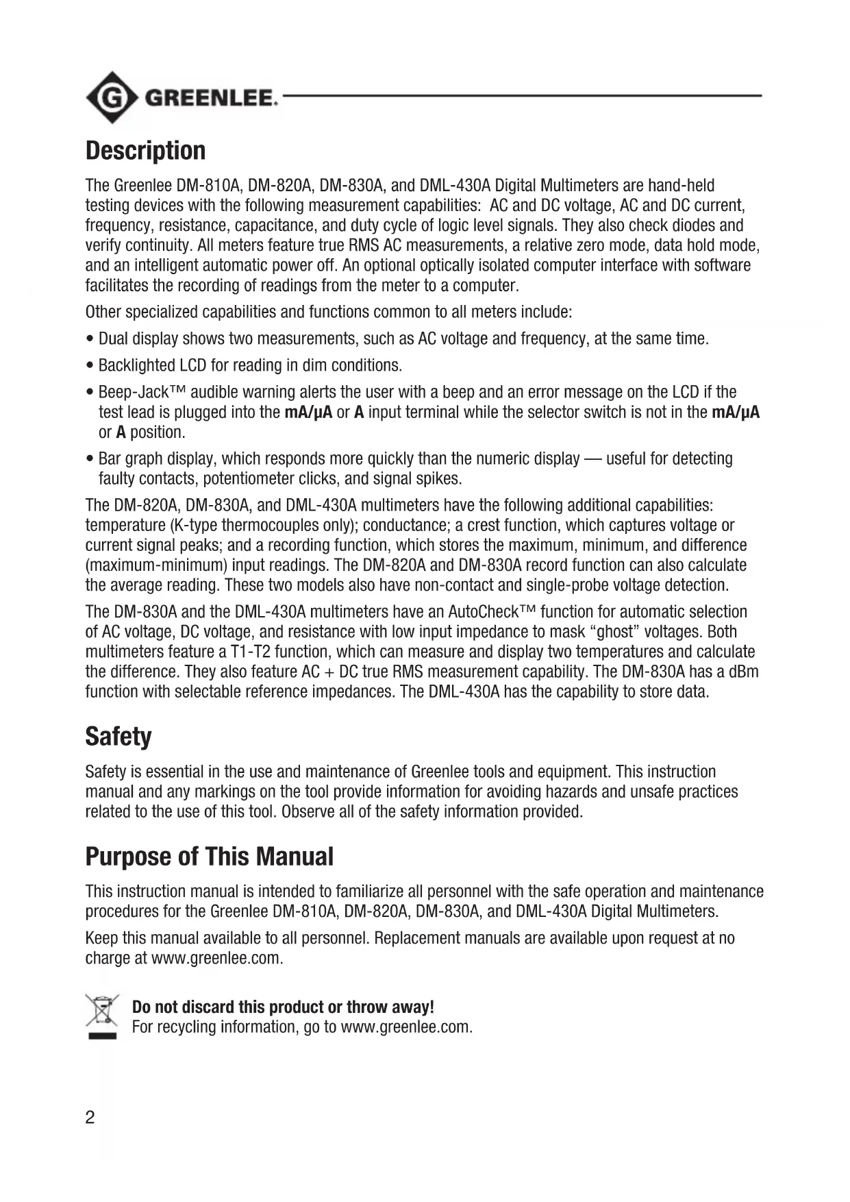
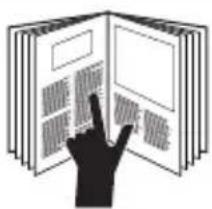
Identification
- Display LCD and bar graph
- Feature Buttons Refer to explanations under "Using the Features"
- Selector Selects a function or turns power OFF
- A Positive input terminal for high current measurements
- mA μA Positive input terminal for low current measurements
- COM Negative, common, or ground input terminal for all measurements
- V - H Positive input terminal for all measurements except current and temperature measurement T2
Symbols on the Unit

Warning—Read the instruction manual

Double insulation
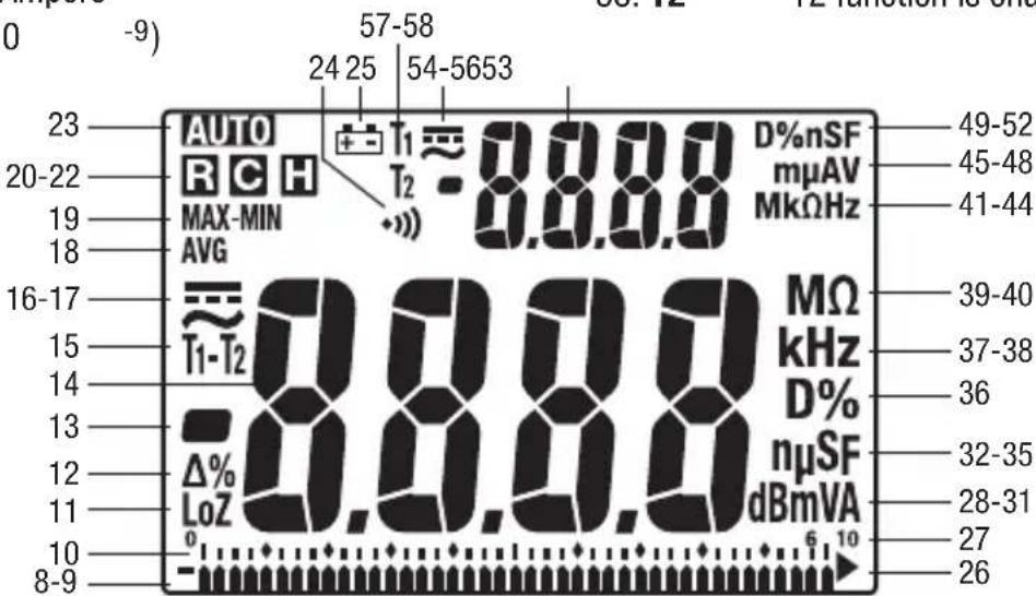
Display Icons
Primary Display
- Bar graph element
-
- Polarity indicator for bar graph
- Bar graph scale
- LoZ AutoCheckTM mode; low input impedance is active.
- Relative zero function is enabled.
-
- Polarity indicator
14.8.8.8.8 Numeric display
- Polarity indicator
- T1-T2 T1, T2, or T1-T2 function is enabled.
- AC measurement is selected.
- measurement is selected.
- AVG AVG function is enabled; recorded value is displayed.
- MAX- Max-Min function is enabled; MIN recorded value is displayed.
- Record function is enabled.
- Crest capture function is enabled.
- Hold function is selected.
- A1T5matic ranging is enabled.
- Continuity
- Low battery
- Overload symbol (bar graph display)
27.10 Bar graph maximum range indicator - dBm Decibel
- m Milli (10^-3)
- V Volt
31.A Ampere -
n Nano (10 -9)
-
Micro (10 -6)
- S Siemen
35.F Farad - D% Duty cycle function is enabled.
- k Kilo (10 3)
- Hz Hertz (frequency in cycles per second)
- M Mega (106)
40.Ω Ohm
Secondary Display
- M Mega (106)
- k Kilo (10 3)
43.Ω Ohm - Hz Hertz (frequency in cycles per second)
- m Milli (10-3)
- Micro (10 -6)
47.A Ampere - V Volt
- D% Duty cycle function is enabled.
- n Nano (10 -9)
- S Siemen
52.F Farad
53.8.8.8.8 Numeric display - measurement is selected.
- AC measurement is selected.
-
- Polarity indicator
- T1 T1 function is enabled.
- T2 T2 function is enabled.
Using the Features
All Models
- Dual Digital Display: These meters can display two measurements, such as AC voltage and frequency, at the same time. Display combinations are shown using large symbols to indicate the measurement on the primary display and small, raised symbols to indicate the measurement on the secondary display. For example, "VAOHz" means the primary display contains the AC voltage measurement, and the secondary display contains the frequency measurement.
- SELECT: Press momentarily to toggle between functions, or to toggle between AC and DC when measuring current and millivolts.
- RANGE: Press once to enter the manual ranging mode. The AUTO icon will disappear from the display. Press repeatedly to step through the ranges. Press and hold to return to the automatic ranging mode.
Note: When using MAX-MIN, HOLD, or mode, pressing RANGE will cause the meter to exit that mode.
- : Finds the difference between two measurements. While taking a measurement, press to set the display to zero. The icon will appear on the display. Take the second measurement. The value on the display will be the difference between the two measurements. Press again to exit this mode.
- HOLD: Press momentarily to hold the present value on the display. Press again to exit this mode. This feature does not affect the bar graph.
- Press and hold until backlight illuminates. Press and hold again to turn off. The backlight automatically turns off after approximately 30 seconds to extend battery life.
- Automatic Power Off: To extend battery life, the meter will shut itself off after approximately 30 minutes of inactivity. To restore power, press either the SELECT, RANGE, , or HOLD button momentarily, or turn the selector to OFF and then back on. To disable this feature, press SELECT while turning the meter on.
- Disabling the Beeper: Hold down the RANGE button while turning the meter on to temporarily disable the beeper feature. Turn the selector to OFF and then back on to enable the beeper.
DM-820A, DM-830A, and DML-430A Only
- CREST: Press momentarily to activate the crest recording mode. The input value is measured every 1 ms in this mode. And "MAX" will appear on the display. The LCD will display the maximum crest value. Press repeatedly to select the desired display: maximum, minimum, or maximum-minimum crest value. Press and hold to exit this mode.
The automatic power off feature is disabled when using this function.
Note: When using the CREST function, pressing RANGE will cause the meter to exit this mode.
- RECR: Press momentarily to activate the MAX/MIN/AVG recording mode. The input value is measured every 50 ms in this mode. "MAX MIN" and "AVG" will appear on the display. The LCD will display the actual input value. The meter will beep whenever the maximum or minimum is updated. Press repeatedly to select the desired display: maximum, minimum, maximum-minimum, average*, or actual input. Press and hold to exit this mode.
*Average function is not available on DML-430A.
The automatic power off feature is disabled when using this function.
Using the Features (cont'd)
Note: When using the REC function, pressing RANGE will cause the meter to exit this mode.
DM-820A and DM-830A Only
-
EF: Set the meter to any current or voltage function. Press and hold until the meter displays "EF" to detect the electric field that surrounds current-carrying conductors. Signal strength is displayed as a series of dashes on the display.
-
Use the tester's built-in antenna (located along the top, near the LCD) for tracing live circuits or locating a break in a wire.
- For more precision, such as distinguishing between current-carrying and ground wires, connect a test lead to the + input terminal and use it as a probe for direct contact verification of a signal.
DM-830A and DML-430A Only
-
Low Impedance AutoCheck™ Mode: In this mode, the meter automatically selects the proper measurement based on the input.
-
If there is no input, "Auto" appears on the display.
- If the voltage is above approximately 1.5 volt DC or 3 volt AC up to the rated 1000 volts, voltage is displayed.
- If both AC and DC voltages are present, the larger voltage is displayed.
- If no voltage is present and there is resistance less than 60M , resistance is displayed. If the measured resistance is below the continuity threshold (between 20 and 300 ), then the continuity tone will sound.
This mode features low input impedance to mask stray or "ghost" voltage pickup. The input impedance is approximately 3k at low voltage, increasing to approximately 460k at 1000V .
The symbol "LoZ" indicates that the meter is in a low impedance mode. Do not use the AutoCheckTM mode on circuits that could be damaged or activated by such low input impedance. Instead use the selector to select the high impedance AC or DC volt modes to minimize loading for such circuits.
Range-Lock and Function Feature: While in the AutoCheck™ mode, press the SELECT button momentarily to lock the displayed function. Press the RANGE button momentarily to lock the displayed measurement range.
Energized Circuit Alert: If the resistance mode is locked in the AutoCheck™ mode and the leads are placed across an energized circuit, the meter will emit an audible warning tone.
- T1-T2: Press momentarily to select the desired temperature display: T1, T2, T1T2, or T1-T2T2.
- dBm- (DM-830A only): In dBm mode, press momentarily to select the reference impedance. Refer to the "Specifications" section for the available values.
- Blue Feature Buttons (DML-430A only): Refer to the "Data Storage Function" section for an explanation of these features.
AC Measurement
AC measurements are usually displayed as RMS (root mean square) values. The RMS value is equal to the value of a DC waveform, which would deliver the same power if it replaced the time-varying waveform. Two AC measurement methods are average-responding RMS calibrated and true RMS-reading.
The average-responding RMS calibrated method takes the average value of the input signal after full wave rectification, multiplies it by 1.11, and displays the result. This method is accurate if the input signal is a pure sine wave.
The true RMS-reading method uses internal circuitry to read the true RMS value. This method is accurate, within the specified crest factor limitations, whether the input signal is a pure sine wave, square wave, triangle wave, half wave, or signal with harmonics. The ability to read true RMS provides much more measurement versatility. The Greenlee DM-810A, DM-820A, DM-830A, and DML-430A are true RMS meters.
The Waveforms and Crest Factors table shows some typical AC signals and their RMS values.
Waveforms and Crest Factors
| Waveform | ||||
| RMS Value 100 | 100 100 100 | |||
| Average Value 90 | 100 87 64 | |||
| Crest Factor* (ξ) | 1.414 1 1.73 | 2 |
- The crest factor is the ratio of the peak value to the RMS value; it is represented by the Greek letter .
AC + DC True RMS
AC + DC true RMS calculates both of the AC and DC components given by the expression
$$ \sqrt {(A C r m s) ^ {2} + D C ^ {2}} $$
when making measurements and responds accurately to the total effective RMS value regardless of the waveform. Distorted waveforms with the presence of DC components and harmonics may cause:
- Transformers, generators, and motors to overheat
- Circuit breakers to trip prematurely
Fuses to blow - Neutrals to overheat due to the triplen harmonics present on the neutral
- Bus bars and electrical panels to vibrate
The DM-830A and DML-430A are AC + DC true RMS meters.
Data Storage Function (DML-430A only)
The DML-430A has data storage and retrieval capability. It can store up to 87,000 measurements in single display mode or 43,000 measurements in dual display mode. The data can later be reviewed on the multimeter's display, or downloaded the data to a computer using the optional interface DMSC-9U.
When in the recording mode, the meter takes a measurement, assigns that measurement to the next available memory location, and repeats the process. This continues until the memory is full or until the user manually stops the recording process.
The time interval between measurements (sampling rate) is selected by the user. A shorter time interval will provide information about short-term fluctuations, whereas a longer time interval will provide information about general trends. The factory setting is the shortest time interval.
The time intervals are as follows: 0.05 seconds (0.1s for single T1/T2, Diode, and Ohms/nS; 0.5s for Hz and Duty Cycle; 2s for Capacitance and dual screen T1/T2 and T1-T2), 0.1s, 0.5s, 1s, 2s, 3s, 4s, 5s, 10s, 15s, 30s, 60s, 120s (two minutes), 180s (three minutes), 300s (5 minutes), and 600s (10 minutes). The minimum total measurement time for the DML-430A is 72 minutes and 30 seconds; the maximum is nearly 20 months.
When the sampling rate is 30s or greater, the meter will go to standby mode between measurements to extend battery life. When the meter is in the standby mode, press SELECT momentarily to view the display.
To set the measurement interval:
Press for 1 second or more and the meter will display the current measurement interval in seconds. Press or to change the measurement interval. Press for 1 second or more to save the new setting.
To start recording data:
Press the button for 1 second or more to start the data logging mode.
"LEFT" displays followed by the number of remaining memory in the logger. The number in the secondary display is the most significant digit, and the numbers in the primary display are the least significant digits of the remaining memory points.
Momentarily press the Yes button to confirm a new logging session without erasing the formerly logged ones (up to 999 sessions can be stored without overwriting previous sessions). Press the Erase button momentarily to erase all of the sessions and start from the first session with full memory.
"Strt" will display on the primary screen and then the logger will start recording. When a sampling speed of 30s or longer is selected, the meter will enter a power down mode after 4.5 minutes. Press the SELECT button momentarily to resume real time display.
Options—duringrecording:
- Press the SELECT button momentarily to toggle the display mode between measuring data and logged data item number. The secondary display contains the most significant number and the primary display contains the least significant numbers of the logged data item number.
- Press the button momentarily to pause/resume logging.
Data Storage Function (DML-430A only) (cont'd)
To stop recording data:
While the meter is logging data, press the button for more than 1 second.
To review stored data:
Press and momentarily to enter Recall mode. The last session number displays for 0.5 seconds and then displays the last logged data item as well the Rnd nunciators.
Options -while reviewing data:
- Press or momentarily to step through the data.
- Press SELECT to toggle between the data and the logged data item number.
- Press and hold or to quickly scan through the data. Tone indicates that the first or last measurement is displayed.
- Press and momentarily to select another session page.
- Press and for 1 second for fast scrolling, and hold either or to quickly scroll through the pages. Tone indicates that the first or last session page is displayed.
- Press or momentarily while holding down the HOLD button to scan through the turning points (the alternating high and low points) or the data set. "MAX" or "MIN" will flash to indicate a high or low point.
To exit Recall mode, rotate the selector to a different setting or turn the meter off.
Using the Optional Software
These meters are compatible with Greenlee DMSC-9U, an optically isolated computer interface cable and software. It allows measurements to be logged to a personal computer using the Microsoft® Windows® operating system. It also allows retrieval of data stored in the internal memory of DML-430A.
Installing the Software
- Insert the CD into the computer's CDROM drive.
- The installation program should launch automatically. If it does not, double click on the CD icon in "My Computer."
- The installation program menu will appear. Click on "Software Installation."
- Type your meter's catalog number (for example, "DM-820A") in the dialog box.
- Complete the remaining dialog boxes according to user preferences.
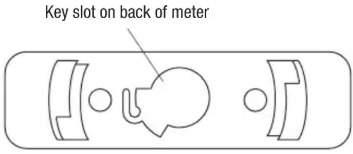
Connecting the Optical USB Interface Cable
- Align the key of the connector with the key slot on the meter.
- Twist the connector clockwise until it locks into place.
- Connect the cable to a USB port of the PC.
Operation

WARNING
Electric shock hazard: Contact with live circuits could result in severe injury or death.
- Refer to the Settings Table. Set the selector to the proper setting, press SELECT (when instructed to do so), and connect the test leads to the meter.
- Refer to "Typical Measurements" for specific measurement instructions.
-
Test the unit on a known functioning circuit or component.
-
If the unit does not function as expected on a known functioning circuit, replace the battery and/or fuses.
-
If the unit still does not function as expected, call Greenlee for technical assistance at 800-435-0786.
-
Take the reading from the circuit or component to be tested.
Settings Table
The meter stores the last used function of each selector position in its nonvolatile memory. If this is not the correct function when you turn the selector, press SELECT until the desired icon appears.
The dual display options are shown along with the icons. In the table, “~Hz” indicates that “~” and “V” appear in the primary display, and “Hz” appears in the secondary display. This combination shows the AC voltage measurement in the primary display and frequency in the secondary display.
| To measure this characteristic ... | Set the selector to this symbol ... | Press SELECT until these icons appear on the display ... | Connect the red lead to ... | Connect the black lead to ... |
| All Models | ||||
| Voltage—AC (1000 V max) | ~V | ~VHz or Hz~V | ΩV-↑ | COM |
| Voltage—DC (1000 V max) | ~V | =V or V~V | ΩV-↑ | COM |
| Voltage—DC (600 mV max) | mV | = mV or mV~mV | ΩV-↑ | COM |
| Voltage—AC (600 mV max) | mV | ~mHz or Hz~mV | ΩV-↑ | COM |
This table continues on the next page.
Operation (cont'd)
Settings Table (cont'd)
| To measure this characteristic ... | Set the selector to this symbol ... | Press SELECT until these icons appear on the display ... | Connect the red lead to ... | Connect the black lead to ... |
| All Models (cont'd) | ||||
| *Frequency—Logic Level | JU Hz | Hz | ΩV-H | COM |
| Frequency—Line Level Voltage or Current | Set for voltage or current according to this table. | Any display option that includes Hz | —— | |
| % Duty Cycle D% D% | ΩV-H | COM | ||
| Resistance Ω Ω | ΩV-H | COM | ||
| Continuity | ··· | ··· | ΩV-H | COM |
| **Capacitance F | -H | ΩV-H | COM | |
| Diode V and diod | + | ΩV-H | COM | |
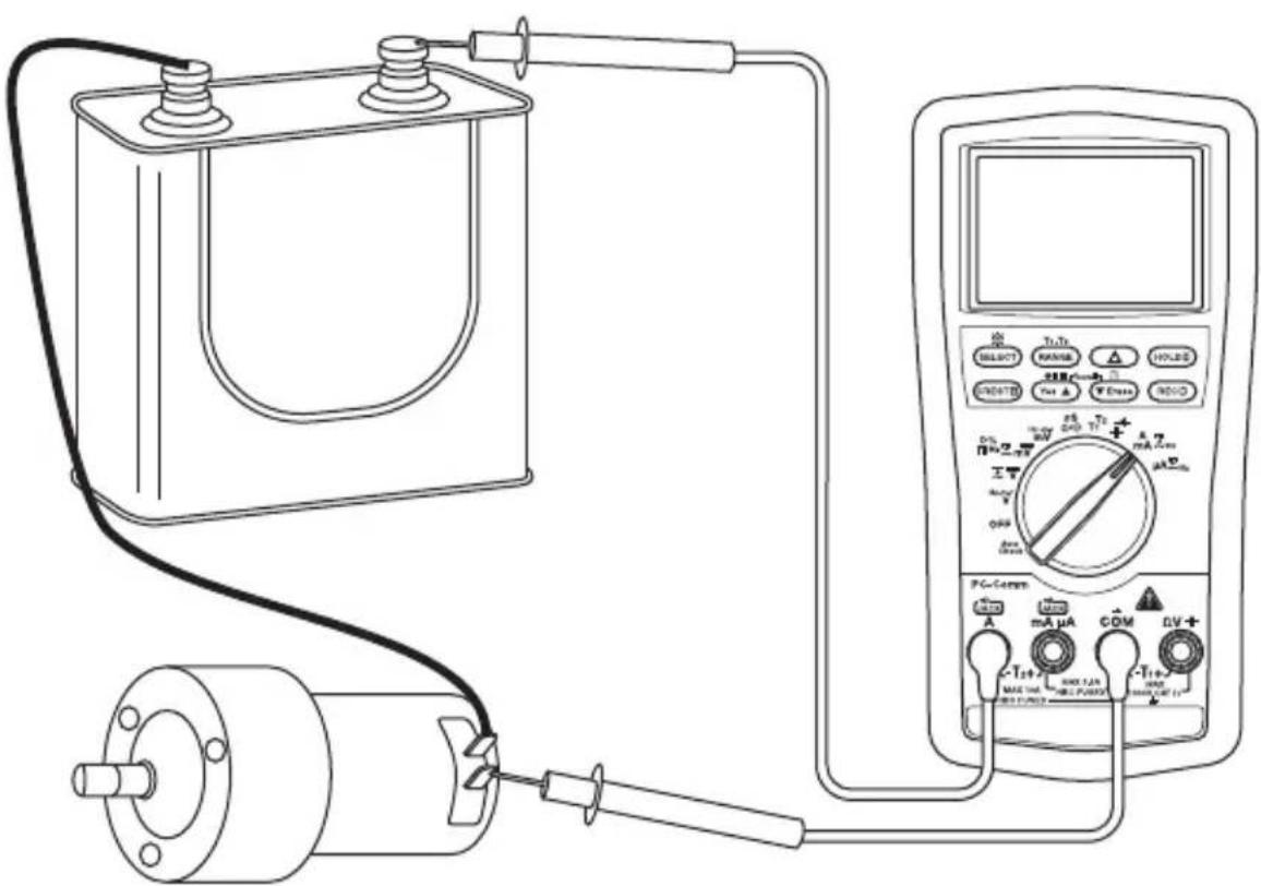
| Current—AC/DC (10 A max) | A | ---A, A---A or A Hz | A COM | |
| Current—AC/DC (600 mA max) | mA | ---mA, mA~mA or mA Hz | mAμA COM | |
| Current—AC/DC (6000 μA max) | μA | ---μA, μA~μA or μA Hz | mAμA COM | |
| DM-820A, DM-830A, and DML-430A Only | ||||
| Conductance nS | nS | ΩV-H | COM | |
| Temperature (DM-820A) | Temp | °C or °F | See Note 1 | — |
| Dual Temperature (DM-830A and DML-430A) | T1T2 | °C or °F (press RANGE for display options T1, T2, T1T2 or T1-T2T2) | See Notes 1 and 2 | — |
| DM-820A and DM-830A Only | ||||
| †EF (electric field detection) | Any voltage or current function; press and hold EF for 1 s or more | EF | ΩV-H (contact mode only) | — |
Operation (cont'd)
Settings Table (cont'd)
| To measure this characteristic ... | Set the selector to this symbol ... | Press SELECT until these icons appear on the display ... | Connect the red lead to ... | Connect the black lead to ... |
| DM-830A and DML-430A Only | ||||
| Voltage—AC + DC True RMS (1000 V max) | V | ≈ V~V | ΩV-H | COM |
| Voltage—AC + DC True RMS (600 mV max) | mV | ≈ mV~mV | ΩV-H | COM |
| Current—AC + DC True RMS (10 A max) | A | ≈ A~A | A COM | |
| Current—AC + DC True RMS (600 mA max) | mA | ≈ mA~mA | mAμA COM | |
| Current—AC + DC True RMS (6000 μA max) | μA | ≈ μA~μA | mAμA COM | |
| †Auto select AC volts, DC volts, resistance, and continuity (low impedance measurement) | AutoCheck | LoZ and AUTO (LoZ with V= V or Ω when using Feature Lock) | ΩV-H | COM |
| DM-830A Only | ||||
| dBm (0 dB = 1 mW in reference impedance) | dBm | Reference impedance and dBm for 1 s, then dBmHz (press RANGE to change reference impedance) | ΩV-H | COM |
- Logic level frequency has a fixed sensitivity and is for digital signals. Refer to "Accuracy".
** Discharge capacitor before measurement. Refer to "Typical Measurements" regarding polarized capacitors.
† Refer to “Using the Features” for a detailed description of this mode.
Note 1: T1+ connects to V and T1- connects to COM.
Note 2: T2+ connects to mAμA and T2- connects to A.
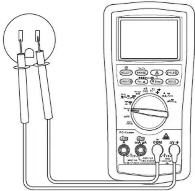
Typical Measurements
Voltage Measurement
Current Measurement
Typical Measurements
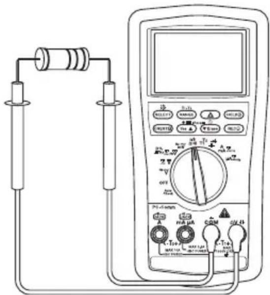
Resistance Measurement
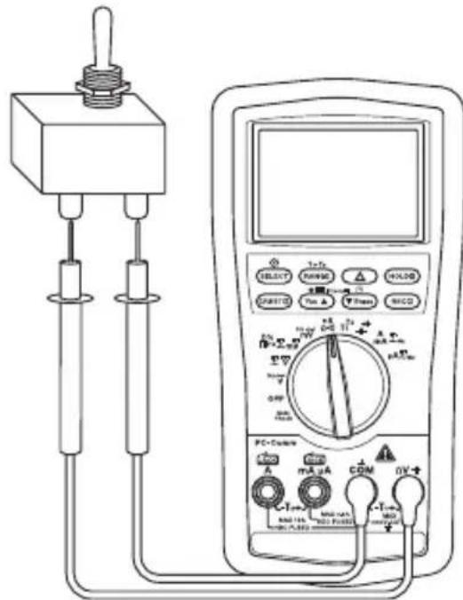
Continuity Check
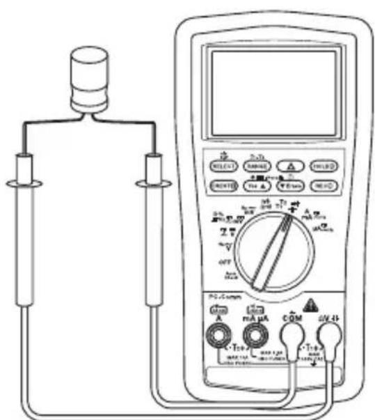
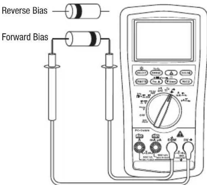
Capacitance Measurement Diode Measurement
Typical Measurements
Temperature
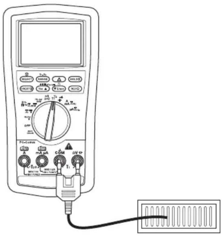
Electric Field Detection (EF)
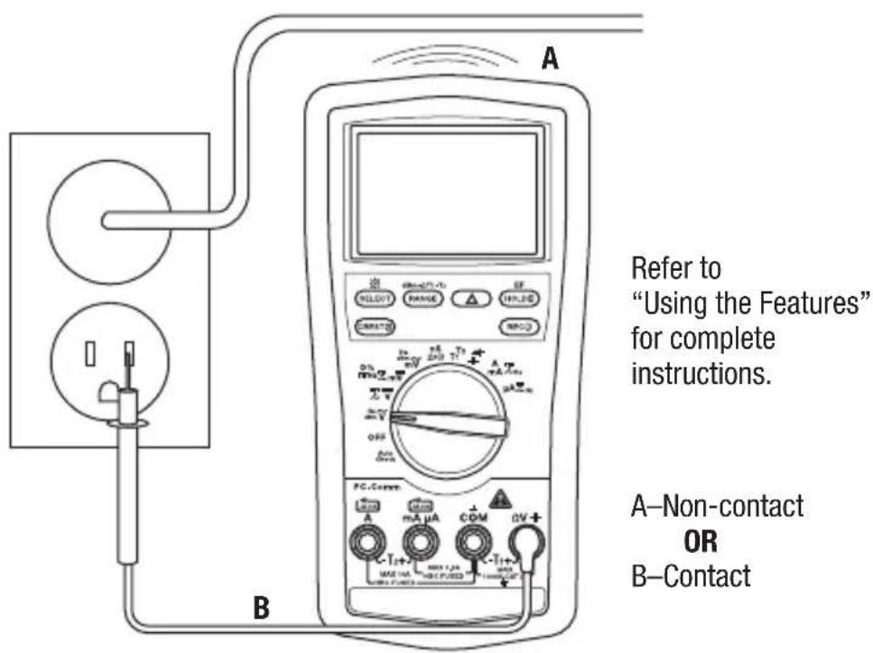
Refer to "Using the Features" for complete instructions.
A-Non-contact OR B-Contact
Accuracy
Refer to the "Specifications" section for operating conditions and temperature coefficient.
Accuracy is specified as follows: ± (a percentage of the reading + a fixed amount) at 23^ ± 5^ ( 73.4^ ± 9^ ), 0% to 75% relative humidity.
True RMS Readings: Voltage and current accuracies are specified from 10% to 100% of the range unless otherwise specified. Frequency must be within the specified bandwidth for non-sinusoidal waveforms. Crest factors are as follows:
- Crest factor < 3:1 at full scale
- Crest factor < 6 : 1 at half scale
All Models
AC Voltage (AC + DC Voltage on DM-830A and DML-430A Only)
| Range | Accuracy at 50 to 60 Hz | Accuracy at 40 to 500 Hz | Accuracy at 500 Hz to 1 kHz | Accuracy at 1 to 3 kHz | Accuracy at 3 to 20 kHz |
| 60.00 mV | ± (0.5% + 0.03 mV) | ± (0.8% + 0.04 mV) | ± (2.0% + 0.03 mV) | ± (2% + 0.03 mV) | ± (2% + 0.03 mV)(1) |
| 600.0 mV | ± (0.5% + 0.3 mV) | ± (0.8% + 0.4 mV) | ± (2.0% + 0.3 mV) | ± (2% + 0.3 mV) | ± (2% + 0.3 mV)(1) |
| 9.999 V | ± (0.5% + 0.003 V) | ± (1.0% + 0.004 V) | ± (1.0% + 0.004 V) | ± (3% + 0.004 V) | 3 dB(2) |
| 99.99 V | ± (± (0.5% + 0.03 V) | ± (1.0% + 0.04 V) | ± (1.0% + 0.04 V) | ± (3% + 0.04 V) | 3 dB |
| 999.9 V ± | (0.5% + 0.3 V) ± (2.0% + 0.4 V) ± (2 | 0% + 0.4 V) ± (3% + 0.4V) Unspecified | |||
(1) Specified from 30% to 100% of range Input Impedance: 10 MΩ, 50 pF nominal (80 pF nominal for 600 mV range) (2) Range bandwidth to 15kHz only
DC Voltage
| Range Accuracy | |
| 60.00 mV ± (0.12% | + 0.02 mV) |
| 600.0 mV ± (0.06% | + 0.2 mV) |
| 9.999 V ± (0.08% + | 0.002 V) |
| 99.99 V ± (0.08% + | 0.02 V) |
| 999.9 V ± (0.08% + | 0.2 V) |
Input Impedance: 10 MΩ, 50 pF nominal (80 pF nominal for 600 mV range)
Accuracy (cont'd)
Resistance and Conductance (Conductance on DM-820A, DM-830A, and DML-430A Only)
| Range Accuracy Typical Open Circuit Voltage | |
| 600.0 Ω ± (0.1% + 0.3 Ω) | 1.2 VDC |
| 6.000 kΩ ± (0.1% + 0.003 kΩ) | |
| 60.00 kΩ ± (0.1% + 0.03 kΩ) | |
| 600.0 kΩ ± (0.1% + 0.3 kΩ) | |
| 6.000 MΩ ± (0.4% + 0.003 MΩ) | |
| 60.00 MΩ ± (1.5% + 0.05 MΩ) | |
| 99.99 nS ± (0.8% + 0.1 nS) 1.2 VDC |
Continuity
Tone Threshold: Between 20 Ω and 300 Ω
Response Time: < 100~ s
Capacitance
| Range Accuracy | (1) |
| 60.00 nF ± (0.8% + | 0.03 nF) |
| 600.0 nF ± (0.8% + | 0.3 nF) |
| 6.000 μF ± (1.0% + | 0.003 μF) |
| 60.00 μF ± (2.0% + | 0.03 μF) |
| 600.0 μF(2) | ± (3.5% + 0.5 μF) |
| 6.000 mF(2) | ± (5.0% + 0.005 mF) |
| 25.00 mF(2) | ± (6.5% + 0.05 mF) |
(1) Accuracies with film capacitor or better
(2) In manual ranging mode, measurements are not specified below 50.0 F , 0.54mF , and 5.4mF for 600.0 F , 6.000mF and 25.00mF ranges, respectively
Diode Test
Measuring Range: 2.000 V
Test Current (typical): 0.4mA
Open Circuit Voltage: < 3.5 VDC
Accuracy: 1.0% + 0.001V
Accuracy (cont'd)
AC Current (AC + DC Current on DM-830A and DML-430A Only)
| Range | Accuracy at 50 to 60 Hz | Accuracy at 40 to 1 kHz | Burden Voltage (typical) (all frequency ranges) |
| 600.0 μA ± (0.6% + 0.3 μA) ± (0.8% + 0.4 μA) | 0.08 mV/μA | ||
| 6000 μA ± (0.6% + 3 μA) ± (0.8% + 4 μA) | |||
| 60.00 mA ± (0.6% + 0.03 mA) ± (0.8% + 0.04 mA) | 2.1 mV/mA | ||
| 600.0 mA ± (1.0% + 0.3 mA) ± (1.0% + 0.4 mA) | |||
| 6.000 A ± (0.8% + 0.006 A) ± (0.8% + 0.006 A) | 0.02 V/A | ||
| 10.00 A ± (0.8% + 0.06 A) ± (0.8% + 0.06 A) | |||
10 A continuous, 20 A for 30 sec. maximum with 5 minute cool down.
DC Current
| Range Accuracy at 50 to 60 Hz | Burden Voltage (typical) (all frequency ranges) |
| 600.0 μA ± (0.2% + 0.4 μA) | 0.08 mV/μA |
| 6000 μA ± (0.2% + 4 μA) | |
| 60.00 mA ± (0.2% + 0.04 mA) | 2.1 mV/mA |
| 600.0 mA ± (0.2% + 0.4 mA) | |
| 6.000 A ± (0.2% + 0.004 A) | 0.02 V/A |
| 10.00 A ± (0.2% + 0.04 A) |
10 A continuous, 15 A for 30 sec. maximum (20 A for DML-430A) with 5 minute cool down.
Line Level Frequency
| Function | Sensitivity (Sine RMS) | Range |
| 60.00 mV | 40 mV | 15.00 Hz to 50.00 kHz |
| 600.0 mV | 60 mV | 15.00 Hz to 50.00 kHz |
| 9.999 V | 2.5 V | 15.00 Hz to 10.00 kHz |
| 99.99 V | 25 V | 15.00 Hz to 10.00 kHz |
| 999.9 V | 100 V | 15.00 Hz to 10.00 kHz |
| 600.0 μA | 45 μA | 15.00 Hz to 3.000 kHz |
| 6000 μA | 600 μA | 15.00 Hz to 3.000 kHz |
| 60.00 mA | 40 mA | 15.00 Hz to 3.000 kHz |
| 600.0 mA | 60 mA | 15.00 Hz to 3.000 kHz |
| 6.000 A | 4 A | 15.00 Hz to 3.000 kHz |
| 10.00 A | 6 A | 15.00 Hz to 3.000 kHz |
Accuracy (cont'd)
Accuracy for Frequency Ranges
| Display Range Accuracy | |
| 99.99 Hz ± (0.04% + 0.04 Hz) | |
| 999.9 Hz ± (0.04% + 0.4 Hz) | |
| 9.999 kHz ± (0.04% + 0.004 kHz) |
Frequency—Logic Level
Range: 5.00Hz to 1.000 MHz
Accuracy: ± (0.004% + 4 digits)
Sensitivity: 2.5 Vp square wave
% Duty Cycle
Input Frequency: 5 Hz to 10 kHz
DM-820A, DM-830A, and DML-430A Only
Temperature (DM-820A) and Dual Temperature (DM-830A and DML-430A)
| Range Accuracy | |
| -50 °C to 1000 °C ± (0.3% + 2 °C) | |
| -58 °F to 1832 °F ± (0.3% + 5 °F) |
Type-K thermocouple range and accuracy not included
Crest Capture (Voltage and Current) for Crests >1.0 ms in duration
Accuracy: Specified accuracy + 250 digits
Record Mode for changes >100 ms in duration
Accuracy: Specified accuracy + 10 digits
DM-820A and DM-830A Only
Electric Field Detection
| Typical Voltage Bar Graph Indication (1) | Frequency Range | |
| 10 V to 36 V- | 50 Hz to 60 Hz | |
| 23 V to 83 V- - | ||
| 59 V to 165 V- - - | ||
| 124 V to 330 V- - - - | ||
| More than 250 V | - - - - - | |
(1) Bar graph indication and tone are proportional to signal strength
Detection Antenna: Top end of the meter
Probe-Contact EF-Detection: For more precise indication of live wires, use the V test probe for direct contact measurements
Accuracy (cont'd)
DM-830A and DML-430A Only
DC Voltage AutoCheck™ Mode
| Range Accuracy | |
| 9.999 V ± (0.5% + 0.003 V) | |
| 99.99 V ± (0.5% + 0.03 V) | |
| 999.9 V ± (0.5% + 0.3 V) |
Input Impedance: Initial 3.0k // 165 pF typical at voltages up to 50 V; increases with voltage to approximately 500 kΩ at 1000 V
Auto Check Trigger Level: > +1.5 VDC and < -1.0 VDC typical
AC Voltage AutoCheck™ Mode
| Range (50/60 Hz) Accuracy |
| 9.999 V ± (1.0% + 0.004 V) |
| 99.99 V ± (1.0% + 0.04 V) |
| 999.9 V ± (1.0% + 0.4 V) |
Input Impedance: Initial 3.0k // 150 pF typical at voltages up to 50 V; increases with voltage to approximately 460k at 1000 V
Auto Check Trigger Level: >1.0V (50/60 Hz) typical
Resistance AutoCheckTM Mode
| Range Accuracy | |
| 600.0 Ω ± (0.5% + 0.4 Ω) | |
| 6.000 kΩ ± (0.5% + 0.004 kΩ) | |
| 60.00 kΩ ± (0.5% + 0.04 kΩ) | |
| 600.0 kΩ ± (0.5% + 0.4 kΩ) | |
| 6.000 MΩ ± (0.8% + 0.003 MΩ) | |
| 60.00 MΩ ± (2.0% + 0.05 MΩ) |
Open Circuit Voltage: < 1.2VDC ( < 1.0VDC for 60M range)
dBm (DM-830A Only)
Range and accuracy are subjected to ACmV, ACV, and reference impedance selected.
Typical 600 Ω reference impedance ranges: At ACmV: -42.22 dBm to -02.22 dBm At ACV: -17.78 dBm to 62.22 dBm
Input Impedance: 10 MΩ, 50 pF nominal
Selectable reference impedance of 4, 8, 16, 32, 50, 75, 93, 110, 125, 135, 150, 200, 250, 300, 500, 600, 800, 900, 1000, 1200 Ω
Specifications
Display:
9999 counts: ACV, DCV, Hz, and nS
6000 counts: mV, A, mA, A, ohm, and capacitance
Polarity: Automatic
Sampling Rate:
Numeric Display: 5 per second
41-Segment Bar Graph Display: 60 per second
Temperature Coefficient: Nominal 0.15 × (specified accuracy) per ^ C
below 18^ or above 28^
Automatic Power Off: After 30 minutes of inactivity.
To disable this feature, press SELECT while turning the meter on.
Noise Rejection*:
Normal Mode Rejection Ratio >60 dB at 50Hz and 60Hz when measuring DCV
Common Mode Rejection Ratio >60 dB from 0 Hz to 60 Hz when measuring ACV
Common Mode Rejection Ratio >120 dB at 0 Hz, 50 Hz and 60 Hz when measuring DCV
Operating Conditions:
0^ to 45^ (32^ to 113^) 0% to 80% relative humidity (non-condensing)
Altitude: 2000m (6500') maximum
Indoor use only
Pollution Degree: 2
Storage Conditions: -20^ to 60^ (-4^ to 140^)
0% to 80% relative humidity (non-condensing)
Remove battery.
Battery: 9-Volt (NEDA 1604, JIS 006P or IEC 6F22)
Overload Protections:
A and mA: 0.44 A/1000 V DC/AC rms, interrupting rating 10kA , F fuse,13/32" x 1-1/2"
A: 11 A/1000 V DC/AC rms, interrupting rating 20kA , F fuse, 13/32" x 1-1/2"
V: 1100 V DC/AC rms
mV, , and Other Functions: 1000V DC/AC rms
Safety: Double insulation per IEC/UL/EN61010-1 Ed. 3.0, IEC/EN61010-2-030 Ed. 1.0, IEC/EN61010-2-
033 Ed. 1.0, IEC/UL/EN61010-031 Ed. 1.1 and CAN/CSA-C22.2 No. 61010-1-12 Ed. 3.0 to Category
IV 1000 VAC and VDC
All Terminals: Category IV 1000 VAC and VDC
CENELEC DIRECTIVES: These meters conform to CENELEC Low-voltage directive 2006/95/EC and
Electromagnetic compatibility directive 2004/108/EC
-
Noise rejection is the ability to reject unwanted signals, or noise.
-
Normal mode voltages are AC signals that can cause inaccurate DC measurements. NMR
(Normal Mode Rejection Ratio) is a measure of the ability to filter out these signals.
Common mode voltages are signals present at the COM and + input terminals, with respect to
ground, that can cause digit rattle or offset in voltage measurements. CMRR (Common Mode
Rejection Ratio) is a measure of the ability to filter out these signals.
Measurement Categories
These definitions were derived from the international safety standard for insulation coordination as it applies to measurement, control, and laboratory equipment. These measurement categories are explained in more detail by the International Electrotechnical Commission; refer to either of their publications: IEC 61010-1 or IEC 60664.
Measurement Category I
Signal level. Electronic and telecommunication equipment, or parts thereof. Some examples include transient-protected electronic circuits inside photocopiers and modems.
Measurement Category II
Local level. Appliances, portable equipment, and the circuits they are plugged into. Some examples include light fixtures, televisions, and long branch circuits.
Measurement Category III
Distribution level. Permanently installed machines and the circuits they are hard-wired to. Some examples include conveyor systems and the main circuit breaker panels of a building's electrical system.
Measurement Category IV
Primary supply level. Overhead lines and other cable systems. Some examples include cables, meters, transformers, and other exterior equipment owned by the power utility.
Statement of Conformity
Greenlee Tools, Inc. is certified in accordance with ISO 9001:2008 for our Quality Management Systems.
The instrument enclosed has been checked and/or calibrated using equipment that is traceable to the National Institute for Standards and Technology (NIST).
Maintenance
WARNING
Electric shock hazard:
Before opening the case, remove the test leads from the circuit and shut off the unit.
Failure to observe these warnings could result in severe injury or death.
WARNING
Electric shock hazard:
The fuses are an integral part of the overvoltage protection. When fuse replacement is necessary, refer to "Specifications" for the correct type, size, and capacity. Using any other type of fuse will void the overvoltage protection rating of the unit.
Failure to observe this warning could result in severe injury or death.
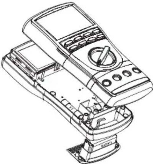
Replacing the Battery
- Disconnect the unit from the circuit. Turn the unit OFF.
- Remove the two screws from the battery access door and remove it.
- Replace the battery making sure to observe the polarity.
Replacing the Fuses
- Disconnect the unit from the circuit. Turn the unit OFF.
- Remove the two screws from the battery access door and remove it.
- Unscrew the two screws inside the battery compartment and the two screws on the back case.
- Remove the back cover and replace the fuses.
- Align the two halves of the unit and the rubber gaskets.
- Be sure the selector is in the original position so that it lines up properly with the internal switch.
- Replace the cover and screws.
Cleaning and Storage
Periodically wipe the case with a damp cloth and mild detergent; do not use abrasives or solvents.
If the meter will not to be used for periods longer than 60 days, remove the battery and store it separately.
Descripción
| Escala Precisión | |
| 600.0 Ω ± (0.5% + 0.4 Ω) | |
| 6.000 kΩ ± (0.5% + 0.004 kΩ) | |
| 60.00 kΩ ± (0.5% + 0.04 kΩ) | |
| 600.0 kΩ ± (0.5% + 0.4 kΩ) | |
| 6.000 MΩ ± (0.8% + 0.003 MΩ) | |
| 60.00 MΩ ± (2.0% + 0.05 MΩ) |
dBm (DM-830A uniqueness)
Protections antisurcharge :
Lifetime Limited Warranty
Greenlee Tools, Inc. warrants to the original purchaser of these goods for use that these products will be free from defects in workmanship and material for their useful life, excepting normal wear and abuse. This warranty is subject to the same terms and conditions contained in Greenlee Tools, Inc.'s standard one-year limited warranty.
For all Test Instrument repairs, contact Customer Service at 800-435-0786 and request a Return Authorization.
For items not covered under warranty (such as items dropped, abused, etc.), a repair cost quote is available upon request.
Note: Prior to returning any test instrument, please check replaceable batteries or make sure the battery is at full charge.