Comfortalarm 22301 - Surveillance Camera TREBS - Free user manual and instructions
Find the device manual for free Comfortalarm 22301 TREBS in PDF.
Frequently Asked Questions - Comfortalarm 22301 TREBS
Questions des utilisateurs sur Comfortalarm 22301 TREBS
0 question sur cet appareil. Repondez a celles que vous connaissez ou posez la votre.
Poser une nouvelle question sur cet appareil
Download the instructions for your Surveillance Camera in PDF format for free! Find your manual Comfortalarm 22301 - TREBS and take your electronic device back in hand. On this page are published all the documents necessary for the use of your device. Comfortalarm 22301 by TREBS.
USER MANUAL Comfortalarm 22301 TREBS
natural_image
Collection of white electronic devices including a TACBS sensor, smart lock, and remote control unit (no visible text or symbols)INHOUD
text_image
Labeled photo of electronic devices including a T2B phone, alarm unit, and various household appliances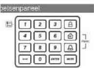
Ovarig
Declaration of Conformity
Company: Trebs BV
Declares that the following products of the Trebs Comfortalarm model 22301:
description: Auto Dialer
Smart Panel
Key Fob Remote
Wireless door sensor
Wireless motion sensor
Is herewith confirmed to comply with the requirements set in the Council Directive on the Approximation of the
Member States relating to
Auto dialer
LVD Directive 2006/95/EC
Electro Magnetic Compatibility Directive 2004/109/EC
Smart Panel:
.Dut-9..Dut-10.
1995 / 5/ EC R&TTE Directive 89/336/ECC & 2006/95/EC
Remote Control
1995 / 5/ EC R&TTE Directive 89/336/ECC & 2006/95/EC
Wireless sensors (door and motion sensor):
1995/5/FC R&TTE Directive 89/336/ECC & 2006/95/FC
Assessment of compliance of the product with the requirements relating to EMC was based on the following
standards:
EN 55022:206+A1:2007
EN55024:1998+A1:2001+A2:2003
EN61000-3-2:2006
EN61000-3-3: 1995 | A1:2001 | A2:2005
The requirements relating to LVD directive was based on the following standards:
EN 60950-1:2006
The requirements relating to R &TTE directive was based on the following standards.
ETSI EN 300 220-1 V2.1.1 (2006-04)
ETSI EN 300 220-2 V2.1.2 (2007-06)
ETSI EN 301 489-1 V1.8.1 (2008-04)
ETSI EN 301 489-3 V1.4.1 (2002-08)
EN 60950-1:2006
INSTALLATIE- EN GEBRUIKSINSTRUCTIES DRAADLOZE TELEFOONKIEZER MODEL 22301
natural_image
White electronic device with digital display and keypad, no visible text or symbolsDeclaration of Conformity
Company: Trebs BV
Declares that the following products of the Trebs Comfortalarm model 22301
description: Auto Dialer
Is herewith confirmed to comply with the requirements set in the Council Directive on the Approximation of the Member States relating to:
Auto dialer:
LVD Directive 2006/95/EC
Electro Magnetic Compatibility Directive 2004/108/EC
The requirements relating to LVD directive was based on the following standards
EN 60950-1:2006
FCCCE
comfortalarm®
TREBS
COMFORT PRODUCTS
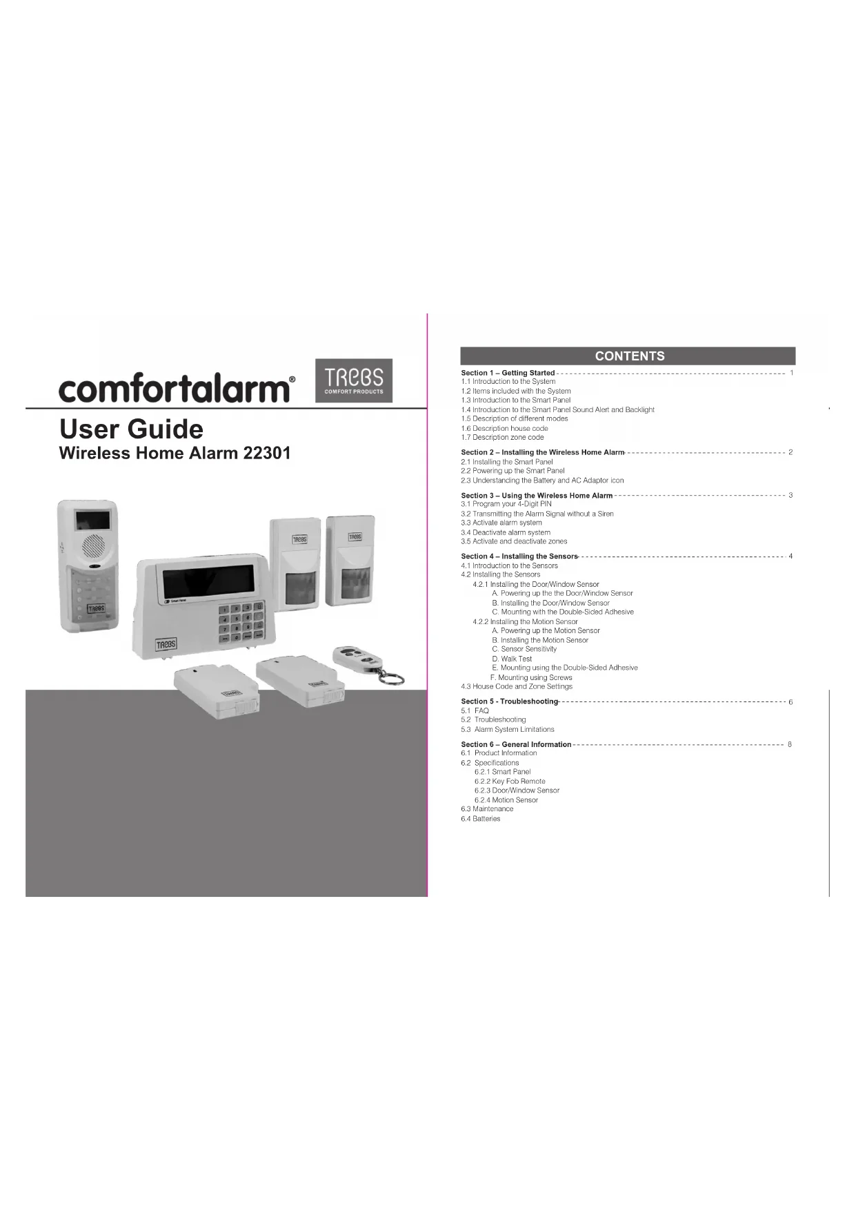
User Guide
Wireless Home Alarm 22301
natural_image
Product photo of TREC device components including a digital display, control panel, and remote control unit (no visible text or symbols)CONTENTS
Section 1 - Getting Started
1.1 Introduction to the System
1.2 Items included with the System
1.3 Introduction to the Smart Panel
1.4 Introduction to the Smart Panel Sound Alert and Backlight
1.5 Description of different modes
1.6 Description house code
1.7 Description zone code
Section 2 – Installing the Wireless Home Alarm 2
2.1 Installing the Smart Panel
2.2 Powering up the Smart Panel
2.3 Understanding the Battery and AC Adaptor icon
Section 3 – Using the Wireless Home Alarm 3
3.1 Program your 4-Digit PIN
3.2 Transmitting the Alarm Signal without a Siren
3.3 Activate alarm system
3.4 Deactivate alarm system
3.5 Activate and deactivate zones
Section 4 - Installing the Sensors
4.1 Introduction to the Sensors
4.2 Installing the Sensors
4.2.1 Installing the DoorWindow Sensor
A. Powering up the the Door/Window Sensor
B. Installing the Door/Window Sensor
C. Mounting with the Double-Sided Adhesive
4.2.2 Installing the Motion Sensor
A. Powering up the Motion Sensor
B. Installing the Motion Sensor
C. Sensor Sensitivity
D. Walk Test
E. Mounting using the Double-Sided Adhesive
F. Mounting using Screws
4.3 House Code and Zone Settings
Section 5 - Troubleshooting-
5.1 FAQ
5.2 Troubleshooting
5.3 Alarm System Limitations
Section 6 – General Information 8
6.1 Product Information
6.2 Specifications
6.2.1 Smart Panel
6.2.2 Key Fob Remoto
6.2.3 Door/Window Sensor
6.2.4 Motion Sensor
6.3 Maintenance
6.4 Batteries
Section 1 – Getting Started
CAUTION! 9V battery in the Smart Panel is for power backup purposes only and you should ensure proper AC power is supplied to the Smart Panel at all times.
Difficulty in disarming the Smart Panel in alarm mode may occur when it is powered by battery alone. This is not a malfunction, and can be resolved by the use of a fresh 9V battery and a properly plugged in DC source from the AC/DC adaptor included.
IMPORTANT! Due to the strong signal of the alarm, we advise that you change the house code settings following section 4.3 of this manual, if you suspect that one of your in-range neighbors may also be using this alarm system.
1.1 Introduction to the System
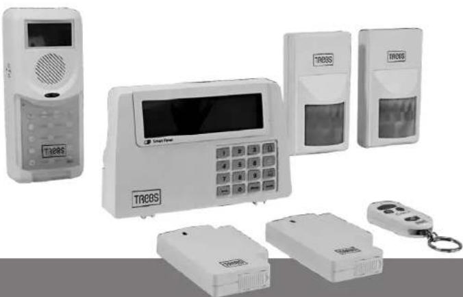
The Wireless Home Alarm 22301 is a high quality security system combined with user-friendly features that allow you to know the state of security of your home at all times. The System is managed by a Smart Panel, which gathers information from wireless sensors placed inside and at the entry points of your home. If the Smart Panel detects a security breach, you will be alerted via indicator lights and sounds. For installation and proper use of the Smart Panel, please familiarise yourself with this User Guide.
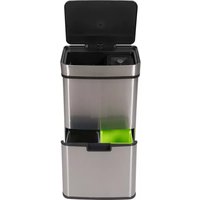
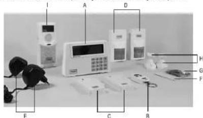
1.2 Items included with the System
Please check that all of the following items were included in the package before installing the System:
A. Smart Panel
B. Key Fob Remote
C. Door/Window Sensor (2 parts)
D. Motion Sensor(2 parts)
E. AC Adaptor for Smart Panel
F. Double-Sided Adhesive for
Doc/Window sensor
G. Screws & Screw Jackets (3 sets)
H. Mounting Bracket for Motion Sensor
1. Auto diale
■ Mounting Template
■ Quick Start Guide
■ User Guido
text_image
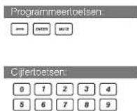
Labeled photo of a home security device with labeled components including alarm, keypad, and phone1.3 Introduction to the Smart Panel
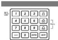
Other
| "9V DC INPUT" port | For AC Adapter |
| Siren output | 120dB |
| Battery Compartment: | For 9V Alkaline Battery Backup battery |
| 4 x Pin Header, 4 x Jumper | For Housea Security code setting |
| 8 x Pin Header, 1 x Jumper | For Zone code setting |
| "Reset" button | If you forget the 4-Digit PIN, press "Reset" button and enter factory default PIN "1 2 3 4 "followed by" to restore factory setting |
1.4 Introduction to the Smart Panel Sound Alert and Backlight
Operating mode:
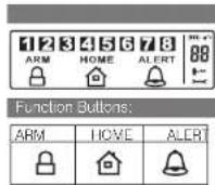
| Mode | Backlight Indication (Zone triggering)Sound Output (Zone triggering) | ||
| 1 | Siren - 60secs.ARM | Red backlight will flash and indicate triggered zone (To stop- enter your 4-Digit PIN and press### ) | |
| 2 | HOME | Siren - 60secs. | Red backlight will flash and indicate triggered zone (To stop- enter your 4-Digit PIN and press### ) |
| Chirre - Ding-Dong x 1 | Green backlight will flash and indicate triggered zone (To stop press### ) | ||
| 3 | ALERT | Chirre - Ding-Dong x 1 | Green backlight will flash and indicate triggered zone (To stop press### ) |
| 4 | STANDBY | Silent | Yellow backlight ON for 10secs, after enter into STANDBY mode |
1.5 Description of different modes:
STANDBY: In this mode the alarm system is not active. The key icon is displayed at the bottom right on the display.
ARM: In this mode the alarm system is activated. ARM is shown on the display.
After activating the ARM mode the display counts 15 seconds down. Within these 15 seconds you have to leave the zone. After 15 seconds all zones are activated.
There is a 30-second entry delay with visible countdown function to deactivate the alarm system. Alarm is given after 60 seconds by a siron. The display flashes red and indicates the triggered alarm zone.
HOME: After activating the HOME mode it is immediately armed. The display shows HOME. In this mode zones 1 and 2 are set to ALERT mode. The remaining zones are set to ARM mode. Alarm by zones 1 and 2 is a doorbell signal. The other zones trigger the siren after 60 seconds. The display flashes green for zones 1 and 2, and red for the other zones. The display indicates the triggered alarm zone.
ALERT: After activating the ALERT mode it is immediately armed. The display shows ALERT. The alarm is a doorbell signal. The display flashes green and indicates the triggered alarm zone.
INPUT: After entering the password followed by the key icon is displayed and the system is in INPUT mode. In this mode you can operate and program the system.
1.6 Description house code
The house code must be set, allowing all alarm system components to communicate. Four jumpers on each component must be set to the same code.
1.7 Description zone code
The system has 8 zone codes. This allows you to set on the display, which deflectors are to be armed. In case of alarm the display shows the triggered alarm zone. (Temporarily) deactivate a sensor to deactivate the corresponding zone on the display. Eight jumpers on each component must be set for the zone code. We recommend assigning each sensor to a different zone. See chapter 4, step 2.
Section 2 – Installing the Wireless Home Alarm 22301
2.1 Installing the Smart Panel
Determine the location of the Smart Panel
*Note:
- The panel should be placed within a few feet of an electrical pulley.
- The panel should be easily accessible.
The panel should not be placed near doors or windows that could be accessed by intruders.
- The panel should not be placed near extreme temperature sources (ovens, sloves etc.) or near large metal
objects that could interfere with the wireless performance.
Once you have selected a location for the Smart Panel, you are ready to begin powering up the System.
2.2 Powering up the Control Panel
Unscrew the battery compartment and remove the cover. Insert a new battery noting the polarity Plug in the AC adaptor to the Smart Panel and connect it to a wall socket. Replace the cover and the screw.
| DescriptionStep | Note | |
| 1 | Insert 9V Alkaline backup battery | - You will hear one beep and the backlight will blink within 1 second (Yellow→ Red → Green→ Yellow)The Smart Panel will display the below image[IMAGE]- The Smart Panel will enter "STANDBY" mode after the automatic self-checking is complete.Enter the default: 4 Digit PIN 1, 2, 3,4 |
| 2 | Plug in AC adapter to the DC socket | The AC power supply must be plugged in at all times; a 9V battery functions as BAC LIP power supply only when the AC power supply is interrupted. |
2.3 Understanding the Battery and AC Adaptor Symbols
| Battery icon shows power status below:Full - [IMAGE]High - [IMAGE]Middle - [IMAGE]Low - [IMAGE] | Battery icon shows when the AC power supply is unplugged or interrupted 5V battery functions as BACK UP and the □ symbol means LOW BATTERY. The LCD Backlight flashes yellow for 30 sec. and □ will blink until the new battery is replaced or the AC power supply is plugged in. |
| AC Adaptor icon ⬇√ | When the AC adaptor to the Smart Panel connected to a wall socket, the AC symbol▼ will appearThe backlight will be ON! for 10secs while the AC adaptor connects to the power supply |
Section 3 – Using the Wireless Home Alarm 22301
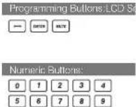
3.1 Programming your new 4-Digit PIN
| Step | Keys | Description | Note |
| 1 | 1 2 34 + symbol | You must be in STANDBY mode before programming your new PIN | *To make sure you are in STANDBY mode: - Enter the factory default PIN "1, 2, 3, 4" - Press -The symbol ← will disappear |
| 2 | +1 | Setting the new PIN | Press then to set the new PIN The screen will show symbols.1 2 3 4 5 6 7 8 |
| 3 | +4-DIGIT PIN+ symbol | Entering the new PIN | Press then enter a 4-Digit PIN (Choose from digits 0 to 9) and press to confirm |
| 4 | +4-DIGIT PIN+ symbol | Re-entering new PIN for confirmation | Press then re-enter your 4-Digit PIN and press for final confirmation^One loop indicates that you entered a valid PIN. Three loops indicate that an invalid operation was performed. |
3.2 Transmitting the Alarm Signal without a Siren
If you are forced to disarm the System, enter the Durose Password to stop the siren from sounding; the Smart Panel will silently transmit the alarm signal to the optional response devices(Auto Dialer & Outdoor Bell Box) for emergency help.
Duress Password:
Enter the default 4-Digit PIN 1 2 3 4 17
OR
Enter your personalised 4-digit PIN +1
3.3 Activate alarm system:
| Slcp | Keys | Description | Note |
| 1 | (1234 / 4-digit code) | STANDBY mode must be active to activate the alarm. | *Follow these steps to ensure that STANDBY mode is activated: - Enter the default code '1, 2, 3, 4' OR your own new 4-digit code - Processors . - The LCD display shows the following image: 1 2 3 4 5 6 7 8 (One beep tone indicates that a valid code has been entered; three beep tones indicate invalid operation.) |
| 2 | Select the desired alarm mode. | Pressoroffor the desired mode. | The system is now activated in the corresponding mode. In ARM mode there is an exit delay of 15 seconds with a visibio countlow function before the system is armed. |
3.4 Deactivate alarm system:
Display: To deactivate the system enter on the display your 4-digit code followed by . The system goes into STANDBY mode. Remote control: To deactivate the system into STANDBY mode enter on the remote control.
3.5 Activate and deactivate zones:
| Stop | Keys | Description | Note |
| 1 | (1234/4-digit code)+ | STANDBY mode must be active to activate the ALERT mode. | *Follow these steps to ensure that STANDBY mode is activated:· Enter the default code '1, 2, 3, 4' OR your own new 4-digit code· Press:- The LCD display shows the following image in activated STANDBY mode:1 2 3 4 5 6 7 8 (One beep tone indicates that a valid code has been entered; three beep tones indicate invalid operation.) |
| 2 | and alarm mode | Pressoroffor the desired mode | Press 1, 2, 3, 4, 5, 6, 7, 8 to activate or deactivate each zone.· If no digit is displayed the corresponding zone is deactivated. |
| 3 | Numeric buttons | 1, 2, 3, 4, 5, 6, 7, 8 | Press the corresponding digit to activate or deactivate the desired zone(s). If no digit is displayed the corresponding zone is deactivated. |
| 4 | Press ENTER to confirm the setting | After limishing the setting set the display to STANDBY mode to set the alarm mode. |
Section 4 – Installing the Sensors
4.1 Introduction to the Sensors
The Wireless Home Alarm 22301 includes 4 wireless Sensors and 1 Key Fob Remote, which have a pro-programmed default setting that begins working immediately once the battery is activated. It is advisable to install the main package first and then personalise the settings once the System is functioning property. This section should help you to change the System settings in order to create a more personal home environment.
4.2 Installing the Sensors
First, determine the location of the sensors.
*Note:
- The Sensors should not be easily accessible.
- The Sensors should be placed in the most vulnerable rooms or near key entry points.
- The Sensors should not be placed near extreme temperature sources (ovens, stoves etc.) or near large metal objects that could interfere with the wireless performance.
Once you have selected a location for the Sensors, you are ready to begin powering up the System.
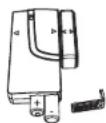
4.2.1 Installing the Door/Window Sensor
The DoorWindow Sensor consists of two pieces. The sensor detects when a door or a window is opened. The two parts are fastened near the door or the window. One part functions as the transmitter and the other as the magnet. Once the Sensor is installed, any abnormality in the circuit will trigger an alert message that is
transmitted to the Smart Panel. 1 x Door/Window Sensor is pre-programmed in Zone 1 and the other one is set in Zone 2; however, the settings can be adjusted according to your needs. (See 3.3 & 4.3 Zono Settings)
A. Powering up the the Door/Window Sensor
- Remove the battery cover; insert new batteries noting the polarity as shown in the diagram below; replace the cover. (Requires 2 - AAA batteries)
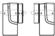
B. Installing the Door/Window Sensor
- Mount the transmitter on a fixed surface such as a door or a window frame.
- Mount the magnet on a movable surface such as a door or a window. -The transmitter side marked with a " > / < " must at same position in both sides per diagrams.
-The transmitter and the magnet must be no more than 0.5mm apart.
C. Mounting with the Double-Sided Adhesive
- Ensure the mounting surface is clean
- Peel back one layer of the protective film and attach it to the transmitter.
- Peel back the remaining layer of protective film and press the transmitter firmly in place against the mounting surface until firmly attached.
- Repeat to attach the magnet
4.2.2 Installing the Motion Sensor
The Wireless Home Alarm includes 2 x Motion Sensor set described as a passive infrared sensor (PIR). PIR sensors are designed to sense movement of anyone or anything that exceeds 36 kg (80 lbs) in a given area. If loss than 36 kg (80 lbs), non alert message is transmitted. Note: Pets larger than 36 kg (80 lbs) must be no more than 1 meter high. It is best if pets are not allowed onto higher surfaces so that the sensors are not triggered unnecessarily. Also, the sensors become increasingly sensitive the closer the movement.
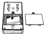
A. Powering up the Motion Sensor
Remove the battery cover; insert a 9V battery noting the polarity as shown in diagram below; replace cover. (Requires 1 x 9V battery)
- Low Battery indication, if the batteries need to be replaced, a slow flashing of the RED LED will indicate low battery (not including entry / exit delay flashing).
B. Installing the Motion Sensor
- First, determine the location of the Motion Sensor.
*Note:
- The Sensor should not be easily accessible.
- The Sensor should be placed in the most vulnerable rooms or near key entry points.
- Place the Sensor on a sturdy surface between 1.8m to 2.4mm (6ft to 8ft) from the floor.
- The Sensor should not be placed near extreme temperature sources (ovens, stoves etc.)
- The Sensor should not be placed in direct sunlight.
- Do not install the Sensor outdoors or behind partitions.
*You have the choice of attaching the Motion Sensor with screws or the adhesive provided
C. Sensor Sensitivity
IMPORTANT! The Motion Sensor is designed with a power saving program. The Motion Sensor will remain
inactive for 3 minutes alter each detection. Thus, during system set up, please bare in mind of this feature during system set up.
The sensitive of the motion sensor is adjustable. Change the setting by placing the connector on either the "High", "Middle" or "Low" position. When the sensitivity is set to "Low", more movement is required to trigger the sensor. It is recommended to set the sensitivity to "Low" and perform a "Walk Test" (Described in part D). If the walk test result is satisfactory, the sensitivity does not require to be adjusted further. If the walk test result shows the sensitivity is too low, then you can change the sensitivity setting to "Middle" or "High" accordingly. Please perform the walk test after changing the sensitivity setting.
D. Walk Test
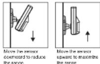
After mounting the sensor at the desired location, it is important to perform a walk test in or determine if the sensor is detecting the correct area.
In order to control how far the sensor can detect motion, you can adjust the angle of the sensor. To reduce the detection range, simply move the sensor downward. To increase the range, move the sensor up to around 12 degrees. This will give the maximum range. However, this may not be desired if the sensor
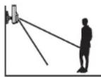
is placed outdoors, since a false trigger may occur if the sensor is set to detect motion in the distance. Disarm the Smart Panel, bell box or dialer before you perform the walk test, so that the alarm is not triggered.
You should walk in the area that you would like the sensor to monitor. If movement is detected the red light inside the unit will appear. If the red light does not appear, adjust the mounting angle accordingly. Perform the walk test again after 30 seconds. Repeat this procedure until your motion is detected. There should be no movement in the detected area during the 30 seconds.
* Tips: The sensor should not face towards direct sunlight. be placed near heat or cold producing devices (i.e. A/C, fans, ovens, healers etc.) that may cause false triggers. Perform walk test in the undesired area to ensure movement cannot be detected.
E. Mounting using the Double-Sided Adhesive
- Ensure the mounting surface is clean.
- Peel back on layer of the protective film and attach it to the back of the Motion Sensor.
- Peel back the remaining layer of protective film and press the Motion Sensor firmly in place against the mounting surface until firmly attached.
F. Mounting using Screws
- Hold the enclosed mounting template against the wall at the selected location and mark the points for drilling. - Drill the holes and insert wall plugs.
- Attach the bracket to the mounting surface with the screws provided. - Attach the Motion Sensor to the mounting bracket.
4.3 House Code and Zone Setting
The Wireless Home Alarm allows you to change the house security codes to avoid interference with different combinations. In most cases you will NOT need to change the factory settings for the house security code. If the Smart Panel and sensors activates intermittently or does not work at all, you may be able to solve the problem by changing your security code.
Step 1: For each device, you will find the 4 jumpers/Dip-Switches. Remove the battery compartment cover, then pull out the Jumper to change the house security code setting and make sure the jumpers on the Smart Panel and it sensor must match exactly.
| Jumpers for house security code |  | -Smart Panel-Door/Window Magnetic Sensor- Motion SensorDefault House code:1: ON, 2: ON, 3: ON, 4: ON*Jumper: ON = Plugged. OFF = Pull Out | |
| Dip-Switches for house security code |  | -Key Rob RemoteDefault house code: 1: ON, 2: ON, 3: ON, 4: ON | |
Step 2: Zone settings of the Sensors
| Jumper for Zone Code | - Determine the location of the Sensor in your home- Pull out the Jumper and reassign it to the target zone (zones to 8). - Replace and screw on the cover to complete the setting change. |
Section 5 - Troubleshooting
5.1 FAQ
Q.1: What is the best way to set up my system? Where should I put my Smart Panel and the sensors?
A.1: We recommend that you take some time in advance to think about the placement of the Smart Panel and Sensors.
The best location for the Smart Panel is usually by the main entry/exit point, in a hallway, or in another central location in your home. The Smart Panel must be plugged into a power socket, which may dictate where it can be placed.
*Please note that the alarm is pre-programmed with default settings, allowing you a pre-determined amount of time to enter (30 seconds) and exit (15 seconds) before the alarm sounds. If the Smart Panel is not near your front door you can either change the default setting to allow more time to enter/exit your home or, alternatively, use the Key Fob to turn the system on and off.
Q.2: How many Sensors can the Smart Panel support?
A.2: An unlimited number of sensors can be supported by the system; you can add 'Optional Sensors' to different zones in your house as you see fit.
Q.3: What wireless range should I expect from Sensors?
A.3: The range will vary depending on the type of structure; however, in an open space, the sensors should be capable of transmitting a signal up to 150 metres from the Smart Panel.
Q.4: How do I attach my Sensors?
A.4: Ahesive tape and screws are provided for the purpose of securely mounting these items. Please refer to the user guide for more information about mounting the Smart Panel and the wireless sensors.
Q.5: Do I have to programme the Smart Panel?
A.5: The Wireless Home Alarm 22301 is designed for easy self-installation. This means that the wireless Sensors are in a default setting already registered to the Smart Panel and will therefore function immediately after the Sensors are powered up. If you choose to buy additional accessories, these will need to be added to your System using the easy to follow instructions.
*Note: We recommend that you install the System using the default settings to ensure that your product functions properly. Once you are familiar with the system you can change the settings to suit your needs.
Q.6: Can I still use the same System if I move?
A.6: The Wireless Home Alarm 22301 is completely portable. If you move, you can remove your Smart Panel and wireless accessories and re-install them in your now property.
Q.7: What if I forget my PIN?
A.7: If you forget your PIN, you may press the "Reset" button inside the battery compartment and the PIN will be reset to the factory default PIN *1, 2, 3, 4".
Q.8: Why does my Motion Sensor not respond to movement?
A.8: Motion Sensor are very sensitive so to preserve battery life the Sensor will go to "Sleep" after an event has been identified and reported to the panel. This "Sleep" period lasts 3 minutes, after which, if no activity is detected, the Motion Sensor will again become active and ready to detect other events.
Q.9: Why does my Motion Sensor keep generating false alarms?
A 9: If you have a pet, make sure they have not triggered the system. Remember, sensitivity to pets increases in certain circumstances e.g. the nearer the pet to the Sensor.
5.2 Troubleshooting
AC Power Failure
This may occur if your security system is accidentally unplugged or if there has been an AC power outage. If a full power failure occurs, please contact your electric company to find out the source of the problem. The backup battery will continue to run the system for approximately 6 hours.
System Battery Failure:
This may occur if the emergency backup battery has been drained and needs to be replaced. If AC power is not restored, the low battery symbol will flash indicating that the Smart Panel backup battery is running low. The back up battery should be replaced once the low battery symbol appears.
Sensor Failure:
This may occur if a sensor is not communicating with the Smart Panel. It is necessary for you to ensure the house security code dipswitch and jumpers of the sensors are set correctly to the Smart Panel.
5.3 Alarm System Limitations
Even the most advanced alarm systems cannot guarantee 100% protection against burglary or environmental problems. All alarm systems are subject to possible compromise or failure-to-warn for a variety of reasons. *Please note that you may encounter problems with your System if:
- The Sensors are not placed within hearing range of persons sleeping or remote parts of the premises.
- The Sensors are placed behind doors or other obstacles.
- Intruders gain access through unprotected points of entry (where sensors are not located).
- Intruders have the technical means of bypassing, jamming, or disconnecting all or part of the system.
- The power to the sensors is inadequate or disconnected.
- The Sensors are not located in proper environmental/temperature conditions i.e. too close to a heat source.
* Inadequate maintenance is the most common cause of alarm failure; therefore, test your system at least once per week to be sure the Sensors and sirens are working properly.
*Although having an alarm system may make you eligible for reduced insurance premiums, the system is no substitute for insurance.
WARNING: Security system devices cannot compensate for loss of life or properly.
Section 6 – General Information
6.1 Product Information
Wireless systems are reliable and tested to high standards; however, it is important to consider that there are some limitations due to their transmitting power and range:
- Receivers may be blocked by radio signals occurring on or near operating frequencies, regardless of the code selected.
- A receiver can only respond to one transmitted signal at a time.
- Wireless equipment should be tested regularly to determine whether there are sources of interference and to protect against faults.
6.2 Specifications
6.2.1 Smart Panel
Power source AC adaptor
Back up power:
Sensor numbers:
House code:
Operating frequencies:
9V alkaline battery x1pc
Unlimited
4 Jumpers
868.35MHz +/-0.5MHz
6.2.2 Key Fob Remote
Power source: 12V Alkaline battery x 1pc
RF working transmission frequency: 868.35MHz +/-0.5MHz
House code: 4 Jumpers
Wireless range to Smart Panel:
65M (Open Area)
6.2.3 Door/Window Magnetic Sensor
Power source: "AAA" Alkaline battery 1.5V x 2pcs
RF working transmission frequency: 868.35MHz +/-0.5MHz
Battery low-level indicator
2.3V | -0.15V
LED Flashing
1Hz+/-0.2Hz
House code: 4 Jumpers
Zone code: Pin header: 8 pin
Wireless range to Smart Panel: >250M (Open Area)
6.2.4 Motion Sensor
Power source: 9V Alkaline battery x1pc
RF working transmission frequency: 868.35MHz 1/-0.5MHz
PIR detection angle: >110 Degree (@9VDC)
PIR deletion range: "H": >15M "M": >6M "L": >4M
PIR retrigger delay: 180s | -30s (@9VDC)
House code: 4 Jumpers
Zone code: Pin header: 8 pin
Wireless range to Smart Panel: >250M (Open Area)
6.3 Maintenance
The product may be cleaned with a soft damp cloth and then wiped dry. Do not use abrasive, solvent based or aerosol cleaners as this may damage and/or discolour the product. Do not allow water to enter or attempt to clean the inside of the unit.
6.4 Batteries
Do not allow batteries to corrode and leak as this may cause permanent damage to the product.
Take care to insert the batteries with the correct polarity as shown inside the battery compartments.
Do not mix new and old batteries or different types of batteries.
Do not fit rechargeable batteries.
At the end of their useful life the batteries should be disposed of via a suitable Recycling Centre. Do not dispose of with your normal household waste, DO NOT BUR N.
Declaration of Conformity
Company: Trebs BV
Declares that the following products of the Trebs Comfortalarm model 22301:
description: Auto Dialer
Smart Panel
Key Fob Remote
Wireless door sensor
Wireless motion sensor
Is herewith confirmed to comply with the requirements set in the Council Directive on the Approximation of the Member States relating to:
Auto dialer
LVD Directive 2006/95/EC
Electro Magnetic Compatibility Directive 2004/108/EC
Smart Panel
1995/5/EC R&TTE Directive B9/336/ECC & 2006/95/EC
Remote Control
1995 / 5/ EC R&TTE Directive 89/336/ECC & 2006/95/EC
Wireless sensors (door and motion sensor):
1995 / 5/ EC R&TTE Directive 89/336/ECC & 2006/95/EC
Assessment of compliance of the product with the requirements relating to EMC was based on the following
standards:
EN 55022: 206 + A1: 2007
EN55024:1998 | A1:2001 | A2:2003
EN61000-3-2: 2006
The requirements relating to LVD directive was based on the following standards
EN 60950-1:2006
The requirements relating to R & TTE directive was based on the following standards:
ETSI EN 300 220-1 V2.1.1 (2006-04)
ETSI EN 300 220-2 V2.1.2 (2007-06)
ETSI EN 301 489-1 V1.8.1 (2008-04)
ETSI EN 301 489-3 V1.4.1 (2002-08)
EN 60950-1:2006
INSTALLATION AND OPERATING INSTRUCTIONS WIRELESS AUTO DIALER 22301
Section 1 – Getting Started
1.1 Introduction to Dialer Plus
The 22301 Dialer Plus can be used as an Emergency Dialer. When triggered by an emergency, the dialer will silently send a pre-recorded message to up to 8 pre-programmed telephone numbers with the first 2 numbers being the priority phone number. People reached by these phone numbers can then listen in and speaking in to the household loud and clear to gain understanding of the nature of the emergency.
The Dialer Plus also works in conjunction with Red Shield's security system 22301. When the alarm from the Smart Panel goes off after receiving reports of intrusion from the sensors, the Dialer-Plus will be activated.
The Dialer-Plus can be activated in the following situations:
-
Panic Buttons on the keypad of Dialer Plus (*) and (#) are pressed down simultaneously.
-
The red "Emergency" button on the is pressed down. (To be purchased separately)
-
Red Shield security system is triggered and sends out the alarm activation signal.
For installation and proper use of the Dialer-Plus, please familiarize yourself with this User Guide.

natural_image
White portable phone with digital display and control panel, no visible text or symbols1.2 Items included with the System
Please check that all of following items were included in the package before installing the dialer.
1 x Dialer
1 x Telephone Line
1 x AC adaptor
Manual
Quick Start Guide
Section 2 – Installing the Dialer Plus
2.1 Determine the location of the Dialer Plus
- The dialer should be placed within a few feet of an electrical outlet, a telephone or near any telephone jack. It's recommend that you hide the dialer from sight for security purposes.
- The dialer should NOT be easily accessible.
- The dialer should NOT be placed near doors or windows that could be accessed by intruders
- The dialer should NOT be placed near extreme temperature sources (oven, stoves etc.) or near large metal objects that could interfere with the wireless performance.
Once you have selected a location for the Dialer Plus, you are ready to begin powering up the dialer.
2.2. Powering up the 22301 Dialer Plus
a.) Back up power: Unscrew the battery compartment and remove the cover. Insert 4 "AA" Alkaline batteries noting the polarity as shown in the battery compartment.
b.) AC Power Supply: Plug in the AC adaptor to the Dialer Plus and connect it to a wall socket.
-LCD will blink within 1 second once powered up
-When the power supply switches from the battery to the AC Adaptor, the [AC symbol] will appear
*Note: 4 "AA" Alkaline batteries serves as backup power when AC power failed, and you should not rely on
battery power and make sure proper AC power is supplied to the dialer at all times. When batteries run low, the "BATT." icon flashes until new batteries are replaced.
2.3. Connect the dialer 22301 to your home telephone:
A phone line must be connected to the dialer in order for the dialer to work.
a. Open the battery door at the back: there are 2 sockets for telephone cables.
b. Connect the "Line" socket to your wall telephone jack.
c. Connect the "Phone" socket to your telephone, which then will share the same phone line with the Dialer plus. Normal telephone functions are interrupted only during emergency, when Dialer plus look control of the phone line.
Section 3 - Programming the Dialer-Plus
3.1 To ENTER the SETUP mode while in the STANDBY Mode:
a. Press "MENU" to activate the keyboard
b. Enter the 4 digit PIN code. (Default PIN code is "1234")
c. Press "ENTER/EXIT" to go into SETUP mode
3.2 To RECORD the message you want to play when the dialer is triggered while in the SETUP Mode
a. Make sure you are in the SETUP mode, following the steps in '3.1"
b. Press and hold "REC/PLAY" for 2 seconds, until the REC shows up on the screen to start the recording.
c. Press the "REC/PLAY" again after you completed recording, or the recording will stop automatically when it reached 20 seconds maximum recording time.
3.3 To RECORD an effective message for help
Makes sure the message includes clear descriptive information of your address and / or your identity (when applicable) for the person you are calling to quickly come to your aid. The message should also contain the simple instruction to allow the person you are calling to start communicating with you over the Dialer plus. For example: "This is a security alert from <"your resident or business name >, at <"your resident or business address >.*After having full listened to this message, please press the hash key (or pond sign), followed by either "1" to "Listening-in" or "3" to "Speaking-in" and so forth. Over"
3.4 To PLAYBACK the recorded message:
a. Make sure you are in the SETUP mode, following steps in "3.1"
b. Press and release the "REC/PLAY" to play back the recorded message
* if you are not satisfied with the recording. You can record the message again, following 3.2 above.
3.5 To CHECK PHONE NUMBERS stored:
a. Make sure you are in the SETUP mode, following steps in "3.1"
b. Press "MENU" (display will show '1' for 1st phone number), press "MENU" again for checking the other phone number
3.6 To ENTER/STORE PHONE NUMBERS:
a. Make sure you are in the SETUP mode, following steps in "3.1"
b. Press "MENU" (Display will show "1" for 1st phone number), Repeat this step to choose which phone numbers
you wish to program (1, 2, 3, 4, 5, 6, 7, 8)
c. Press "PROGRAM" and enter the phone number digits (Maximum 16 digits)
d. Press "CLEAR" to clear a wrong number you entered
e. Press "ENTER/EXIT" to complete this step
* Please note that you should program the numbers in the sequence of importance to you. Dialer will NOT dial later numbers when an earlier person you wish to call has been successfully reached.
3.7 To DELETE a stored phone number:
a. Make sure you are in the SETUP mode, following steps in "3.1"
b. Press "MENU" (Display will show "1" for 1st phone number), Repeat this step to choose which phone numbers
you wish to DELETE (1, 2, 3, 4, 5, 6, 7, 8)
c. Press "PROGRAM" and "ENTER/EXIT" to confirm erasing
3.8 To program the number of DIALING CYCLES
a. Dialing cycle is the number of times you wish the Dialer Plus to phone the stored phone numbers when those
numbers are not answered.
b. Make sure you are in the SETUP mode, following steps in "3.1"
c. Press "MENU" (Display will show "1" for 1st phone number). Repeat this step until the display shows "CYCLE"
d. Press "PROGRAM" and enter the number of cycles you wish (1 through 0, default cycle is 3 times)
3.9 To change the 4-DIGIT PIN
a. Make sure you are in the SETUP mode, following steps in "3.1"
b. Press "MENU" (Display will show "1" for 1st phone number), Repeat this step until display show "KEY"
c. Press "PROGRAM" and enter a new PIN number.
Section 4 – Activating the Dialer
Congratulations. Your Dialer plus is now ready to help in emergency situations. You can test how the Dialer works by pressing both # and * keys on the dialer's keypad for the dialer to dial out to the phone numbers you have stored.
Section 5 - INSTRUCTION FOR THE RECIPIENT
There are several things that your call recipients should know in order to successfully receive and terminate an emergency call from your dialer. Make sure your dialer recipients understand what to do when they receive your emergency call. Therefore, it is a good idea to give them a copy of this page for their reference.
5.1 To START speakerphone conversation
After having full listened to the recorded message, press the hash key (or pond sign), to confirm that the message is NOT merely delivered to a voice mail. So, the "Listening-in" function by pressing "1" and "Speaking-in" function by pressing "3" can only be used when the call recipient pressed the Hash key (#). Time out period is 60 seconds and recipients can extend either the listening time or speaking time by pressing "1" or "3" accordingly. With each pressing, a further 60 seconds will be allowed by the Dialer plus.
5.2 To EXTEND the time out for speakerphone conversation
Time out period is 60 seconds; the recipient can extend the time out for another 60 seconds by pressing (1) to listen-in and (3) to speak-in. The conversation will be disconnected if the dialer receives no instruction.
5.3 To STOP the emergency message of the existing call AND all the remaining calls.
When the message finished, press (#). This will stop the dialer from calling existing number and all the remaining phone number.
This termination will result in disconnecting the existing call and stop calling all the remaining phone numbers. Since this termination will stop the dialer from calling all the phone numbers, so the recipient must know exactly the situation and emergency of the call before terminating it.
5.4 To DISCONNECT all calls after conversation
Once the speakerphone conversation is over, the recipient should disconnect the call by pressing (#) instead of just hanging up the phone. This will terminate the connection for all existing call and the remaining calls.
Section 6 House Security Code and Zone Code Settings
You can change the house security code on each sensor, smart panel and other modules of your security system to avoid interference with other systems.
In most cases you will NOT need to change the factory settings of the house security code. If the Smart Panel and sensors activate intermittently or do not work at all, you may be able to solve the problem by changing the house security codes on all system modules.
Step 1: There are 4 jumpers/dip-switches on each device. Remove the jumper compartment cover, then pull out the Jumper to change the house security code setting and make sure the jumpers on the Smart Panel and it sensors match exactly.
| Jumpers for house security code | - Smart Panel-Each sensorDefault house code:1: ON, 2: ON, 3: ON, 4: ON*Jumper: ON = Plugged, OFF = Pull Out | |
| Dip-Switches for house security code | - Key Fob RemoteDefault house code: 1: ON, 2: ON,3: ON, 4: ON |
Section 7. Maintenance
The product may be cleaned with a soft clamp cloth and then wiped dry. Do not use abrasive, solvent based or aerosol cleaners as this may damage and/or discolour the product. Do not allow water to enter or attempt to clean inside the unit.
Section 8. Batteries
Do not allow batteries to corrode and leak as this may cause permanent damage to the product.
Take care to insert the batteries with the correct polarity as shown inside the battery compartments.
Do not mix new and old batteries or different types of batteries.
Do not fill rechargeable batteries.
At the end of their useful life the batteries should be disposed of via a suitable Recycling Centre. Do not dispose
of with your normal household waste. DO NOT BURN.
Section 9. Alarm System Limitations
Even the most advanced alarm systems cannot guarantee 100% protection against burglary or environmental
problems. All alarm systems are subject to possible compromise or failure-to-warm for a variety of reasons.
*Please note that you may encounter problems with your System if:
● The Sensors are not placed within hearing range of persons sleeping or remote parts of the premises.
● The Sensors are placed behind doors or other obstacles
● Intruders gain access through unprotected points of entry (where sensors are not located).
● Intruders have the technical means of bypassing, jamming, or disconnecting all or part of the system.
● The power to the sensors is inadequate or disconnected
● The Sensors are not located in proper environmental/temperature conditions i.e. too close to a heat source.
* Inadequate maintenance is the most common cause of alarm failure; therefore, test your system at least once
per week to be sure the Sensors and sirens are working properly
*Although having an alarm system may make you eligible for reduced insurance premiums, the system is no
substitute for insurance.
WARNING: Security system devices cannot compensate for loss of life or property
Declaration of Conformity
Company: Trebs BV
Declares that the following products of the Trebs Comfortalarm model 22301:
description: Auto Dialer
Smart Panel
Key Fob Remote
Wireless door sensor
Wireless motion sensor
Is herewith confirmed to comply with the requirements set in the Council Directive on the Approximation of the
Member States relating to:
Auto dialer:
LVD Directive 2006/95/EC
Electro Magnetic Compatibility Directive 2004/108/EC
Smart Panel:
1995/5/EC R&TTE Directive 89/336/ECC & 2006/95/EC
Remote Control:
1995/5/EC R&TTE Directive 89/336/ECC & 2006/95/EC
Wireless sensors (door and motion sensor):
1995 / 5/ EC R&TTE Directive 89/336/ECC & 2006/95/EC
Assessment of compliance of the product with the requirements relating to EMC was based on the following
standards:
EN 55022: 206 + A1: 2007
EN55024:1998 | A1:2001 | A2:2003
EN61000-3-2: 2006
The requirements relating to LVD directive was based on the following standards
EN 60950-1:2006
The requirements relating to R & TTE directive was based on the following standards:
ETSI EN 300 220-1 V2.1.1 (2006-04)
ETSI EN 300 220-2 V2.1.2 (2007-06)
ETSI EN 301 489-1 V1.8.1 (2008-04)
ETSI EN 301 489-3 V1.4.1 (2002-08)
EN 60950-1:2006
comfortalarm®
TREBS
COMFORT PRODUCTS
natural_image
Collection of white electronic devices including a TNCBS sensor, display screen, and remote control unit (no visible text or symbols)SOMMAIRE
Section 1 – Introduction 1
SECTION 1 - INTRODUCTION
DECLARATION OF CONFORMITY
Company: Trebs BV
Declares that the following products of the Trebs Comfortalam model 22301:
description: Auto Dialer
Smart Panel
Key Fob Remote
Wireless door sensor
Wireless motion sensor
Is herewith confirmed to comply with the requirements set in the Council Directive on the Approximation of the Member States relating to:
Auto dialer
LVD Directive 2006/95/EC
Electro Magnetic Compatibility Directive 2004/108/EC
Smart Panel
1995/5/EC R&TTE Directive 89/336/ECC & 2006/95/EC
Remote Control:
1995/5/EC R&TTE Directive 89/336/ECC & 2006/95/EC
Wireless sensors (door and motion sensor)
1995/5/EC R&TTE Directive 89/336/ECC & 2006/95/EC
Assessment of compliance of the product with the requirements relating to EMC was based on the following standards:
EN 55022: 206 + A1: 2007
EN55024: 1998 + A1: 2001 + A2: 2003
EN61000-3-2:2006
The requirements relating to LVD directive was based on the following standards:
EN 60950-1:2006
The requirements relating to R &TTE directive was based on the following standards:
ETSI EN 300 220-1 V2.1.1 (2006-04)
ETSI EN 300 220-2 V2.1.2 (2007-06)
ETSI EN 301 489-1 V1.8.1 (2008-04)
ETSIEN 301 489-3 V1.4.1 (2002-08)
EN 60950-1:2006
INSTRUCTIONS D'UTILISATION ET D'INSTALLATION DU COMPOSEUR AUTOMATIQUE SANS FIL 22301
natural_image
White handheld electronic device with a digital display and keypad (no visible text or symbols)Declaration of Conformity
Company: Trebs BV
Declares that the following products of the Trebs
Description: Auto Dealer
Is herewith confirmed to comply with the requirements set in the Council
Directive on the Approximation of the Member States relating to:
Auto dialer;
LVD Directive 2006/95/EC
Electric Magnetic Compatibility Directive 200410WEC
The representatives relating to IVO devices are based on the following specifications: FN 90653-1, 2006.